
4
Flight Safety Requirements
One of the most important safety responsibilities of the range commanders (i.e., the commanders of the 30th and 45th Space Wings) is to ensure public safety during launch and flight. Range safety personnel evaluate vehicle design, manufacture, and installation prior to launch; monitor vehicle and environmental conditions during countdown; monitor the track of vehicles during flight; and, if necessary, terminate the flight of malfunctioning vehicles. The method used for flight termination depends on the vehicle, the stage of flight, and other circumstances of the failure. In all cases, propulsion is terminated. In addition, the vehicle may be destroyed to disperse propellants before surface impact, or it may be kept intact to minimize the dispersion of solid debris. Flight termination can also be initiated automatically by a break-wire or lanyard pull on the vehicle if there is a premature stage separation.
Current FTS practices have an excellent safety record. From 1988 through November 1999 there were 427 launches at the ER, during which 11 destruct commands were issued (two Atlas II, one Delta III, one Titan IV, four Trident SLBMs, and three other missiles). Over the same time period there were 177 launches at the WR, during which 11 destruct commands were sent (one Athena, two Pegasus, one Titan IV, and seven ICBMs). Total failure of an FTS is extremely rare at either range, and destruct commands are often superfluous because vehicles explode or break up because of dynamic forces before the mission flight control officer (MFCO) can react.
This chapter discusses current and future requirements for flight termination, tracking, and telemetry; examines cost, reliability, and efficiency from the perspectives of both the ranges and the users; and suggests improvements.
TRACKING
A large fraction of range support costs are related to developing, maintaining, and operating accurate and reliable tracking systems. EWR 127-1 requires “at least two adequate and independent instrumentation data sources” for tracking launch vehicles “from T-0 throughout each phase of powered flight up to the end of range safety responsibility” (Paragraph 2.5.4). For space launch vehicles, the ER implements this requirement by mandating two independent tracking sources and full FTS capability from launch through normal engine shutdown subsequent to achieving orbit. The WR requires two independent tracking sources and FTS capability until loss of contact with the vehicle as it approaches and passes over the horizon. Missions at both ranges are allowed to proceed if one source of data is lost during flight, but complete loss of tracking data is a prima facie reason to terminate the flight even if there are no indications that the vehicle is departing from its intended flight path. Thus, the purpose of the two-source requirement is largely to ensure a successful mission—by ruling out the possibility that a good flight will be terminated because a single tracking system fails. Public safety, however, is not based on mission assurance. Safety is provided by the ability to determine when something has gone wrong and, if necessary, safely terminate a flight.
Tracking requirements at both ranges are met through a combination of C-band radar beacons, unaided radar tracking, optics, and vehicle telemetry. Launch vehicle systems include C-band transponders with omnidirectional antennas; two or more flight termination command receivers per vehicle; redundant batteries to power the flight termination receivers; and thrust-termination and vehicle-destruct ordnance, including initiators and safe/arm devices. A real-time vehicle telemetry system also is required to provide telemetered inertial guidance (TMIG) data from the vehicle guidance system, along with other critical data, such as the status of the flight termination receiver and chamber pressures in the engines and solid rocket motors.
Accuracy Requirements
Tracking systems must be accurate, timely, and reliable enough to enable the ranges to calculate accurate IIPs.
EWR 127-1 (Paragraph 2.5.4.1.1) establishes different IIP error standards for the WR and ER. The ER believes that the current limits are overly restrictive and has proposed relaxing them in the next version of EWR 127-1 (Campbell, 1999). For the ER, crossrange and downrange error in IIP must be no more than 100 feet (three sigma)1 until IIP clears the launch area (as currently authorized) or no more than 300 feet (per the proposed change). The proposed change also requires that error in vehicle position not exceed 140 feet in the vicinity of the launch area. At the WR, the allowable error is 1,000 feet. Once the vehicle clears the launch area, IIP crossrange error at the ER must not exceed 0.5 percent of the IIP range, and downrange error may not exceed 5 percent of the IIP range. At the WR, crossrange and downrange errors must not exceed 1 percent of the IIP range. The ER bases estimates of IIP error on static error sources, excluding time lags caused by data transfer and processing delays. The WR incorporates lag errors in its methodology. This may explain the large differences in accuracy requirements between the ranges.
It is essential to account for lag errors in predicting the accuracy of IIPs because range radars cannot satisfy the IIP accuracy requirements in real time. In addition to mechanical pointing lags and various delays in relaying the data to the ROCC (Range Operations Control Center), sequential-difference data derived from the azimuth, elevation, and range data must be “smoothed” to develop the velocity estimate needed to calculate the IIP. This smoothing typically requires several seconds of data. The accuracy of the real-time IIPs is highly sensitive to the velocity value used, and a sudden change in the vehicle thrust vector takes time for the tracking system to detect and display; meanwhile, the actual IIP may be hundreds of feet from the displayed location.
In practice, however, small errors in IIP are not significant. The debris pattern after an explosive flight termination is many thousands of feet across even for an accident 10 to 15 seconds after liftoff, and pinpointing the center of the pattern is not necessary to ensure safety. The committee supports the proposal to relax the tight IIP accuracy requirements currently imposed at the ER for launch vehicles that have not yet cleared the launch area. Satisfying IIP accuracy requirements outside the launch area is well within the capabilities of both radar and GPS tracking systems.
Radar
The ER and WR each have a network of 10 C-band radars. Several of these radars are located at downrange facilities. Each network consists of one phased-array multiple-object tracking radar and nine, generally aging, C-band single-object tracking radars (see Figure 4-1). Ongoing modernization of both ranges will eliminate the need for most of these radars. As currently planned, the modernized ranges will use differential GPS tracking systems supplemented by two radars at the WR and seven radars at the ER. Three of the seven radars at the ER will be necessary only to support launches of the space shuttle, and three others will be located at downrange facilities to support ballistic missile tests and space object identification.
The WR launches vehicles into polar orbits using initial launch azimuths between 158o and 201o. Downrange assets are not needed for these launches because, by the time uprange facilities lose contact with launch vehicles, they no longer pose a threat to inhabited landmasses.
The ER uses initial launch azimuths of 37° to 114°. Northerly trajectories parallel the U.S. and Canadian coasts. Many launch vehicles on easterly trajectories do not achieve orbit prior to flying over Europe or Africa, and African overflight is common for missions with large payloads headed for geo-synchronous orbit. Currently, the ER uses downrange facilities to track vehicles to orbital insertion.2
EWR 127-1 specifies that the ground segment of the tracking system must have a reliability of at least 0.999 for a one-hour duration during the period of range safety responsibility (Paragraph 2.5.4.1.3). EWR 127-1 also says that the reliability requirements for vehicle-based range tracking systems are 0.995 for the C-band transponder systems and 0.999 for GPS-based systems (Paragraph 4.10.3a). A proposed change to EWR 127-1 would establish a slightly lower reliability standard (of 0.96) for each of the two independent sources of tracking data used in a GPS-based system (Cather, 1999).3 The requirement to have two independent tracking sources would not be changed.
TELEMETRY
Telemetered data are routinely collected during launches, and selected items are provided in real time to the range user and to range safety personnel in the ROCC. Data of particular interest to range safety are guidance data, command receiver status, and steering commands.
TMIG data must be used as a tracking source for launch vehicles equipped with an inertial guidance system (EWR 127-1, Section 2.5.5.1). TMIG data are important because they provide vehicle state vectors (which indicate vehicle location and velocity) to determine IIPs with a minimum of data processing. Compared to IIP displays based on
|
1 |
Sigma is a measure of statistical fluctuation. Three sigma means that the probability that the outcome will fall within expected limits (in this case, the probability of having an IIP error of 100 feet or less) should be at least 99.7 percent. The equivalent values for one and two sigma are 68 and 95 percent. |
|
2 |
As discussed in Chapter 3, the committee recommends that the Air Force modify this practice because GPS metric tracking will eliminate range safety requirements for downrange radars for space launches. |
|
3 |
As noted below, the two sources of tracking data used with a GPS system would be (1) a GPS device (translator or receiver) and (2) another, independent GPS device, an inertial measurement unit (IMU), or TMIG. |
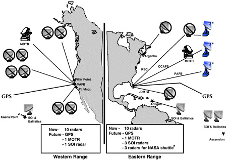
CCAFS = Cape Canaveral Air Force Station
JDMTA = Jonathan Dickinson Missile Tracking Annex
KSC = Kennedy Space Center
MOTR = multiple-object tracking radar
PAFB = Patrick Air Force Base
SOI = space object identification (used to determine satellite size, shape, motion, orientation and operational status)
VAFB = Vandenberg Air Force Base
FIGURE 4-1 Changes in range tracking support under the RSA range modernization program. Source: Finn and Woods, 1999.
data from a single radar, IIP displays based on TMIG data are very low in noise, extremely accurate, and have very little delay.
TMIG data are also useful during tracking system dropouts or overshoots, which occur frequently at major staging events. TMIG data can quickly indicate sudden turns or rotations, and a failure during a staging event can be detected using TMIG data three or four seconds earlier than with radar data. This may be less important with GPS tracking systems, which are expected to reduce lag times. Even so, GPS data links may be interrupted for a second or two by staging events; flight experience will be necessary to determine the effect of staging events more accurately.
Inertial guidance systems can fail in a way that would steer a vehicle off course even though TMIG data indicate that the flight is on course. For this reason, TMIG data must be independently verified by other sources early in flight. At the WR, MFCOs have used TMIG to track ICBMs for three decades, but only after visual comparison of TMIG data with radar data through the beginning of fourth-stage flight. At the ER, MFCOs shift to TMIG as a prime source on SLBM missions when other tracking data becomes unreliable.
At the WR there have been 16 failures involving TMIG during tests of Minuteman III ICBMs. In two cases, TMIG data apparently failed to indicate an off-course condition (Cortopassi, 1999). The first was W7262 launched on January 26, 1972, which missed the Kwajalein target point by five miles because of a human error in prelaunch alignment. The resulting offset early in the trajectory was too small to be detected in real time by radar. In a second incident in March 1990, the TMIG did not show on-course progress, but it indicated a safe condition when, in fact, the IIP was rapidly moving off the nominal flight path. More recently, on August 12, 1998, a Titan IV failure at the ER involved a momentary power failure and reset after the vehicle had pitched over to head downrange. The reset apparently caused the guidance system to act as if the vehicle were still level on the pad; consequently, it reinitiated pitch steering. The vehicle was destroyed by aerodynamic forces (Lyles, 1999).
None of the events just described led to an uncontrolled situation. That would have required multiple independent failures, such as:
-
the loss of primary tracking so that TMIG data become the primary source of tracking data
-
a guidance system failure causing the vehicle to turn to a prohibited azimuth
-
a turn ending before aerodynamic limits have been exceeded, with return to stable flight
-
the absence of any other observations or information indicating the vehicle is off course
The probability that all of these conditions would occur on a single launch is very small. Therefore, the committee believes that TMIG should be allowed to serve as one of the two required sources of tracking data, and the process of verifying TMIG data against other tracking sources should be retained.
Vehicle operators normally have their own requirements for real-time telemetry displays, and only minor changes (and minimal costs) are required to strip out and forward items of interest to the range safety office. Current and planned telemetry equipment can readily handle the various formats, reporting rates, and other differences between launch vehicles and real-time displays.
Stand-alone inertial measurement units (IMUs) also can be used as independent tracking sources. IMUs must be calibrated prior to launch. Also, unless an IMU is connected to a GPS unit or can be otherwise recalibrated during flight, the IMU must include gyros with very low drift rates. Gyros with low drift rates are very expensive, and an acceptable stand-alone IMU might cost almost as much as a full guidance system. However, it is quite feasible to pair a GPS receiver with an IMU costing on the order of $10,000.
Recommendation 4-1. As a matter of good engineering practice, the requirement for two independent sources of tracking data should be retained, and the accuracy of telemetered inertial guidance data should be verified after launch. AFSPC should clarify EWR 127-1 to specify that telemetered inertial guidance data can serve as one of the two sources of tracking data.
GPS METRIC TRACKING
As part of the RSA range modernization program, the Air Force plans to transition both the ER and WR to GPS-based tracking systems. This will affect both range operators and users.
GPS System Options
A GPS system would replace the onboard C-band transponder beacon with either a GPS translator or receiver unit along with appropriate cabling and L-band antennas. Ground-based radars would be replaced with telemetry-receiving equipment compatible with the chosen system.
A GPS translator receives L-band signals from GPS satellites and retransmits them without any processing to the ground on the S-band telemetry link. The alternative, a GPS receiver, would use L-bank signals to calculate vehicle position and state vectors and transmit them to the ground in real time. In both cases, data from the satellite are transmitted to the ground via an S-band communications link and then relayed to the ROCC. The accuracy of translators or receivers can be improved through the use of differential GPS corrections, which employ a fixed receiver on the ground as a reference to account for errors associated with (1) intentional inaccuracies in the signals transmitted by the GPS satellites, (2) small deviations in the orbits of the GPS satellites, and (3) atmospheric effects that distort the GPS signals received by the launch vehicle. Both differential GPS receiver and translator systems, if properly designed and qualified, would be able to meet range requirements for tracking accuracy.
Analog GPS Translator System
Launches of Navy SLBMs conducted offshore from Cape Canaveral use a GPS-based analog translator system for range safety. Simpler versions of this system were used for SLBM launches beginning in 1979. Since the completion of the GPS constellation, the system has not constrained launch timing or flight trajectory. The L-band GPS signals are captured by the vehicle, translated into an S-band transmission, and relayed through appropriate ground-based telemetry receivers to the ROCC. The ground-based receivers are configured to decode the S-band transmission and add correcting algorithms, producing highly accurate vehicle state vectors. The overall accuracy of this system exceeds current requirements, and the system is fully flight operational. However, the GPS analog translator system has some drawbacks. First, a wide bandwidth, in the neighborhood of several megahertz, is required to downlink the GPS signals to the range receivers. This creates a problem because the S-band telemetry spectrum is already overloaded, as are the communications links between downrange sites and the ROCC. Second, noise increases with bandwidth, so more power is needed on the vehicle for an acceptable signal-to-noise ratio. Also, noise is added each time the signal is retransmitted, which may prevent ground-based receivers from locking on to the signals or decoding them in real time.
The ER already operates GPS ground-processing stations to support the launch of Navy SLBMs. As described below, the WR is procuring and installing GPS ground-processing stations capable of supporting both analog and digital GPS translator systems to support ICBM launches.
Digital GPS Translator System
The Air Force Range Instrumentation System Program Office at Eglin Air Force Base is developing a digital GPS
translator system, which translates and transmits L-band GPS signals to the ground in an S-band digital format. Ground processing of the signals to determine vehicle position and velocity are the same as in the analog system after the digital telemetry is decoded. In fact, the current version of the ground translator processor station can process either analog or digitized signals equally well.
Compared to an analog system, the digital system reduces the S-band retransmission bandwidth by a factor of 2 to 10 and reduces the size and weight of the onboard components. The digitized signal provides more robust link margins and facilitates signal relaying, while the reduced transmission bandwidth reduces interference with existing and planned launch vehicle telemetry. These units are being adapted specifically for launches of Air Force ICBMs and are not presently planned or being demonstrated for space launches. Flight qualification is scheduled for completion in early 2000.
GPS Receiver System
GPS receiver systems have been flown experimentally on vehicles at the U.S. Army White Sands Missile Range, at Vandenberg Air Force Base, and on Pegasus vehicles launched on both coasts. The development of an operational GPS receiver for use at the ER and WR is under way. Designs under consideration would enable simultaneous tracking of up to 12 GPS satellites. The vehicle state vector and the intermediate information used to determine the state vector would be transmitted to the ground. The RSA ground support system will include fixed GPS receivers to produce a differentially corrected state vector. The S-band bandwidth necessary to send receiver data to the ground is on the order of 100 times smaller than the bandwidth for a translator system.
Precise estimates of the accuracy and precision of GPS-derived trajectory information must take into account antenna performance, how well corrections can be made for refraction and other errors, the number of satellites used to generate the solution, and other factors. Without differential correction, real-time position accuracy of 500 feet (one sigma) is routinely obtained by receivers used in boats and automobiles. Commercially available differential GPS receivers can provide positional accuracy of significantly less than 100 feet, which is the most stringent accuracy requirement at either of the ranges. GPS systems have demonstrated the ability to maintain lock on the satellite signals at accelerations significantly higher than those expected during booster flight of space launch vehicles. Also, GPS receiver systems can be linked with inexpensive auxiliary IMUs to compensate for momentary loss of signals resulting from staging or other dynamic events. Necessary algorithms have already been developed, and experimental testing has demonstrated their versatility and robustness over a broad range of simulated flight conditions.
Assessing the Alternatives
Costs
Switching to a GPS-based range safety tracking system would mean replacing each onboard C-band transponder with either a GPS receiver system or a GPS translator system with an S-band telemetry transmitter separate from the one used for TMIG data. The digital translator developed for ICBMs is projected to cost roughly $28,000 each (Wells, 1999). The launch-hardened G-12 GPS receiver built by Ashtech being tested at White Sands and Edwards Air Force Base (but is not space qualified) reportedly costs between $25,000 and $30,000. A receiver being built by Rockwell-Collins Radio for the ICBM terminal area study of the Re-entry Vehicle Decoy GPS Experiment is projected to cost $10,000 to $12,000 and will be tested early in 2000 (Finn and Woods, 1999). These devices can track the required number of GPS satellites, and their output data rate satisfies requirements for space launch. However, the performance of the receivers has not yet been validated in terms of data time lags, compatibility with the vibration and temperature environment of flight, and other factors listed in Chapter 4 of EWR 127-1.
The cost and time required to develop a GPS receiver— and for modifying the design of launch vehicle hardware and interfaces to make them compatible with GPS receivers— are still uncertain. SMC estimates it will cost $5 to $10 million to redesign and recertify each family of launch vehicles to use GPS receivers in place of C-band transponders (Finn and Woods, 1999). Some users are concerned that actual costs could be significantly higher. To meet schedule requirements during the transition, existing radars should remain functional long enough to acquire GPS receivers, modify the design of launch vehicles, and conduct flight tests (including operational tests during which users, if they wish, can fly GPS receivers in parallel with traditional radar tracking systems to build confidence in the new systems).
Shifting from radar tracking to GPS receivers will also increase recurring costs for related vehicle systems. The added L-band antennas, L-band low-noise amplifiers, cables, and the GPS receiver/transmitter could double the cost of onboard hardware compared to a C-band transponder system (Smith, 1999). Depending on performance and configuration requirements, the first operational designs could add 10 pounds or more to the weight of the upper stage, resulting in an equivalent reduction in payload capacity. Even so, the life-cycle costs for a GPS receiver tracking system are expected to be much lower than for radar systems because the current single-object radars are aging, expensive to maintain, and would be expensive to replace (see below).
Versatility
Both GPS receivers and translators can be designed and built to meet basic safety requirements related to
qualification tests, data rate, data latency, overall accuracy, and reliability. The performance of both systems is sensitive to the design and placement of the L-band antennas and would differ somewhat (but probably not materially) in the recovery time from momentary dropouts in the L-band signals received from GPS satellites or S-band transmissions to the ground. As already noted, GPS translators require a broader bandwidth and may experience earlier loss of signal lock than receiver systems. Also, if a vehicle equipped with a translator system departs from the planned flight path, flight termination would have to be commanded from the ground; the GPS translator system would not detect the off-course condition because GPS position data would not be available on board.
GPS receivers, which would compute position and velocity data on board, would enable development of FTSs with a higher degree of autonomy. Also, the small bandwidth requirements of receiver systems would be compatible with a space-based range that would use satellites to relay commands, GPS data, and telemetry between the vehicle and the range control center. A space-based range would eliminate the need for virtually all ground-based tracking infrastructure, greatly reduce the need for ground-based telemetry equipment, and allow a control center to support launches almost anywhere in the world. Thus, a GPS receiver system offers operational advantages over either a translator system or the existing radar-based system.
RANGE MODERNIZATION
User costs at both the ER and WR are based, in part, on the ranges’ direct costs of supporting a particular launch (i.e., how much each launch increases the overall cost of range operations). Lockheed Martin Astronautics estimates that the average range costs for each Atlas or Delta launch are on the order of $500,000. In addition, prelaunch tests of the FTS cost $100,000 and tests of the C-band radar tracking beacon and S-band vehicle telemetry system cost another $100,000 (Hillyer, 1999). These costs do not include the cost of standard factory acceptance tests. Lockheed Martin estimates that a “typical” mission scrub costs the range user about $110,000 (Hillyer, 1999). This cost is highly variable, however, depending on the cause of the scrub, how long it takes to reschedule the launch, and the effect of the scrub on the flight status of the vehicle and payload systems.
Of greater concern is the need to upgrade or replace range radars. The vast majority of existing radars were built in the early 1950s, and their continued use will increase the already high cost of maintaining their aging electronics and pointing mechanisms. Increasing age is also expected to increase the failure rate of critical systems and down time for repairs. Increases in average and peak launch rates and shorter launch windows will amplify the impact of unexpected ground system down time and make it more difficult to meet users’ schedule requirements. During the 196 launches at the ER from 1993 through 1998, problems with range instrumentation caused numerous holds but only five launch scrubs. Over the same time period, the WR conducted 92 launches, and instrumentation problems caused three scrubs.
As already discussed, a GPS-based range safety tracking system would eliminate the need for 11 of the 20 tracking radars currently used to support launches at the ER and WR. Studies initiated by SMC show that a GPS-based system would significantly reduce total life-cycle costs (LMTSC, 1996, and Finn and Woods, 1999). Figure 4-2 shows estimates of life-cycle cost for three options: (1) retaining current radars with no major upgrades, (2) modernizing current radars and adding two new ones, and (3) transitioning to a GPS tracking system supplemented by nine radars. The estimates include development costs (of $30 to $60 million) and recurring costs (of $120,000 to $250,000 per vehicle) of implementing a GPS system on all current launch vehicles except the space shuttle. The results do not take into account potential future savings from the elimination of scrubs caused by radar outages, reduced radar infrastructure, easier prelaunch checkout, or the cost to NASA of either modifying the space shuttle fleet to use GPS (estimated by NASA at $32 million) or maintaining a radar tracking capability solely for shuttle operations.
Most of the savings that are explicitly included in Figure 4-2 are in the area of ground system acquisition and maintenance. Because of the way costs are allocated, these savings would primarily benefit the range owner (the Air Force), not users (industry). Costs might also be reduced through collaborative development of new flight safety systems. Until the 1970s the government designed and certified many safety systems and provided them to launch contractors as government-supplied equipment. The committee believes that the time and total cost of shifting to a GPS receiver tracking system could be reduced if government and industry work together to develop and certify new systems that satisfy agreed-upon performance requirements and are compatible with a broad range of launch vehicles in terms of weight, size, and power requirements.
The schedule for deploying GPS receiver tracking systems (i.e., completing the RSA program and related activities) is based primarily on the amount of available funding. In recent years annual funding has been reduced, which has delayed the schedule and increased total program costs. The committee believes it would be worthwhile to restore funding and accelerate the deployment of GPS receiver tracking systems because of the cost savings and operational improvements that would result.
Finding 4-1. For space launches, an onboard GPS receiver tracking system would be more versatile and have lower total life-cycle costs than GPS translator or radar tracking systems.
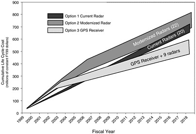
FIGURE 4-2 Comparison of life-cycle costs for radar and GPS-based range tracking systems. Source: Finn and Woods, 1999.
Finding 4-2. Real-time GPS tracking systems have an overall cost and performance advantage over the single-object radar network that has been the workhorse on both the Eastern and Western Ranges for many years. Implementation of a GPS tracking system would increase users’ recurring and nonrecurring costs in the short term, but it would benefit users in the long term by increasing operational flexibility. A GPS tracking system would also yield long-term costs savings for the ranges.
Primary Recommendation on GPS Receivers. AFSPC should deploy a GPS receiver tracking system as the baseline range tracking system for space launch vehicles. The transition to GPS-based tracking should be completed as rapidly as feasible.
Finding 4-3. Upgrades to onboard tracking systems currently in use and to new systems, such as GPS receivers, are relatively costly for individual users. Each user currently must develop or acquire hardware, prove that it meets safety requirements, demonstrate its compatibility with range support equipment, provide for qualification and acceptance testing, and support confidence checks in the final countdown.
Recommendation 4-2. AFSPC should form a range-industry team to define performance requirements and technical specifications for the onboard elements of a GPS receiver tracking system, including cost, weight, size, and power limitations, and to establish user requirements during the transition from radar to GPS-based tracking systems. A cost-shared government/industry project should be established for the development and qualification testing of common end-user equipment. Range users should pay for the recurring costs of onboard hardware.
After the committee had completed its deliberations, representatives of Lockheed Martin Astronautics and the Boeing Company gave the committee copies of an assessment that they had performed on alternative approaches to range modernization. Their assessment concluded that the most cost-effective option would be to use a dual TMIG system in place of a radar or GPS tracking system. Although the committee did not have an opportunity to examine this assessment in detail, some of its assumptions and cost projections seemed questionable. The information received by the committee was not convincing and the committee stands by its recommendation that the ER and WR should be modernized with GPS receiver tracking systems for space launch.
AUTONOMOUS FLIGHT TERMINATION SYSTEMS WITH GPS
GPS-receiver range tracking systems would be compatible with either a fully autonomous FTS or a conventional, human-in-the-loop FTS with enhanced autonomous functions. Some autonomous functions are already operational in the form of inadvertent-separation destruct systems that sense unplanned vehicle breakup and initiate the destruct sequence.
At least three basic methods could be used to implement an autonomous FTS that would assume full FTS responsibility once the launch vehicle clears the launch area. One method is to continuously compute the flight heading, compare it with the expected heading, and terminate the flight if the difference exceeds a predetermined limit. This method could use headings derived from the GPS receiver system, the vehicle guidance system, or an auxiliary IMU.
A second method is to continuously compute position and velocity and compare them with expected values. The flight would be terminated if errors exceeded predetermined limits as a function of flight time. This would be a relatively simple and straightforward way to use GPS data.
A third method is to replicate the current IIP and surface destruct line methodology. This is the most complex of the three methods described here, but it would provide the greatest margin for allowing continued flight of a vehicle that deviates from the intended flight plan but is not yet dangerous. Allowing a flight to proceed under such circumstances provides an opportunity for the vehicle to recover and maximizes the collection of telemetry to support postmission investigations of the problem.
Each of these methods would require a logic unit with validated software to process measured data, such as GPS state vectors; compare them with stored data; and generate commands to the FTS. Like current FTS flight hardware, autonomous FTSs would be designed for high reliability, tested for compatibility with the launch environment, and include means for prelaunch verification of operability.
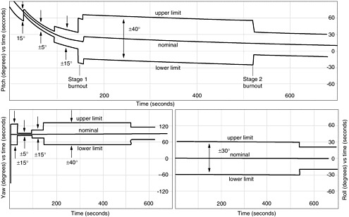
Certain Russian launch vehicles use fully autonomous FTSs, although they do not use GPS (or equivalent) systems. In one example, projected allowable pitch and yaw angle limits based on time from liftoff are stored in the onboard computer and compared to actual launch vehicle flight angles from the guidance IMU. Figure 4-3 shows the limits for a typical Sea Launch mission using a Ukrainian/Russian booster system. The Sea Launch system does not satisfy ER or WR requirements for two independent data sources, but it does demonstrate the feasibility of using autonomous FTSs.
The Israeli Arrow missile uses an automated FTS during portions of flight where the allowable flight path is quite narrow and human reaction time may not be fast enough to terminate the flight of a malfunctioning rocket safely. One Arrow was destroyed by its FTS during a test flight, although some believe the termination could have been avoided if a human operator had been in the primary control loop.
At locations such as the ER, the uprange launch area is the largest contributor to collective risk. An initial approach to autonomous FTS would be to fly the uprange portion of the mission using traditional human-in-the-loop FTS procedures. Then, after Ec has decreased with distance and flight time, the mission could switch to a fully autonomous FTS before leaving the uprange area. A semiautonomous FTS such as this would probably require minimal hardware modifications to the GPS receiver. Retransmission of the GPS-derived position and velocity data on independent S-band links would no longer be necessary, the need for downrange facilities would be further reduced, and practically all uprange tracking and telemetry assets could be eliminated, resulting in very substantial cost savings. The committee believes that the reliability of such a system could be demonstrated to equal or exceed current FTS system requirements.
Although an autonomous FTS system is technically feasible, system performance requirements must be defined, development and validation costs must be accurately estimated, and issues of public acceptability (domestically and internationally) must be addressed to determine if a fully autonomous FTS would be practical and cost effective. The successful deployment of semiautonomous systems, which would provide operational benefits even if a fully autonomous system is never developed, would help resolve these issues. A first step would be to develop computerized simulations of vehicle dynamics and FTS responses to determine system requirements. These simulations could be followed by validation testing using sounding rockets or other low-cost test vehicles.
Finding 4-4. With the incorporation of onboard GPS receivers, semiautonomous and fully autonomous flight termination systems would become technically feasible. These systems might substantially reduce range support costs, but additional research and testing is needed to resolve outstanding issues and quantify the likely benefits.
REUSABLE LAUNCH VEHICLES
Many different organizations are developing commercial RLVs, some of which may someday operate from the ER or WR. The basic safety criteria for RLVs should be the same as for expendable launch vehicles in terms of Ec, Pc, and Pi. Even so, range safety processes for RLVs require special attention because RLV concepts vary greatly in design and operational characteristics. In addition, RLVs that carry human beings raise additional safety of flight issues, especially with respect to the acceptability of autonomous or semiautonomous FTSs. FAA regulations and EWR 127-1 should facilitate efforts by range users to obtain launch authorizations using means of compliance that make sense for the
vehicle being launched. The committee did not attempt to develop specific means of compliance for new classes of RLVs because they will vary with the design of each vehicle. However, streamlining EWR 127-1 to focus on performance-based requirements, in accordance with the Primary Recommendation on EWR 127-1, would be an important first step toward the routine launch of commercial RLVs from either the WR or ER. In the long term, developing space-based ranges would increase operational flexibility and reduce turnaround times. These improvements will be important to support future RLVs, which will also have a high degree of operational flexibility and short turnaround times.
REFERENCES
Campbell, M. 1999. EWR 127-1 Change Request 97-2-009. Submitted by M. Campbell, 45th Space Wing, June 30, 1999. Available on line at: http://www.pafb.af.mil/45sw/rangesafety/99cr.htm January 21, 2000.
Cather, C. 1999. EWR 127-1 Change Request 97-4-003. Submitted by C. Cather, 30th Space Wing, April 23, 1999. Available on line at: http://www.pafb.af.mil/45sw/rangesafety/99cr.htm January 21, 2000.
Cortopassi, R. 1999. Memorandum from R. Cortopassi, 30 SW/SE, to Director of Safety, 30 SW. Updated Minuteman III History. July 9, 1999.
EWR 127-1 (Eastern and Western Range Safety Requirements). 1997. Available on line at: http://www.pafb.af.mil/45sw/rangesafety/ewr97.htm January 20, 2000.
Finn, G., and T. Woods, 1999. Briefing materials on Spacelift Range Metric Tracking Life-Cycle Cost Review. August 10, 1999. Briefing materials prepared by G. Finn, Aerospace Corporation and T. Woods, Air Force Space and Missile Systems Center, in response to a request by the Committee on Space Launch Range Safety, August 13, 1999.
Hillyer, T. 1999. Atlas Space Launch Vehicles—System Cost. Briefing by Tom Hillyer, Lockheed Martin Astronautics, to a panel of the Committee on Space Launch Range Safety, Lockheed Martin Astronautics, Denver, Colorado, June 24, 1999.
ICF Kaiser Consulting Group. 1999. Environmental Assessment for The Sea Launch Project. Prepared for the Federal Aviation Administration, February 12, 1999. Available on line at: http://ast.faa.gov/pdf/sea_launch January 24, 2000.
LMTSC (Lockheed Martin Tactical Systems Company). Global Positioning System Trade Study. August 1996. Fort Worth, Texas: Lockheed Martin Tactical Systems Company.
Lyles, L. 1999. U.S. Department of Defense Assessment of Space Launch Failures. November 1999. Available on line at: http://www.af.mil/lib/misc/spacebar99.htm January 21, 2000.
Smith, D. 1999. LMA Comments to GPS Metric Tracking Initiative. Briefing by Dan Smith, Lockheed Martin Astronautics, to a panel of the Committee on Space Launch Range Safety, Lockheed Martin Astronautics, Denver, Colorado, June 24, 1999.
Wells, L. 1999. Translated GPS Range Systems. Briefing by Lawrence Wells, L3 Communications−Interstate Electronics, to the Committee on Space Launch Range Safety, Santa Maria, California, July 12, 1999.


