
B Effects of Technology on Sensor Size and Design
This appendix supplements the discussion in Chapter 3 on the physical limits of sensor sizing by examining the effects of technology with regard to building more compact sensors.
For the purposes of this discussion, consider the generic electro-optical sensor as a transducer that ingests photons and ejects a digital bit stream. Although there are many other classes of sensors that are of interest—such as active electro-optical lidars and active and passive microwave sensors—the fact that passive electro-optical sensors account for a major portion of the Earth Observing System (EOS) and National Polar-orbiting Observational Environmental Satellite System payload suites makes them a reasonable focus for this discussion.
Figure B.1 illustrates some of the key subsystems associated with the photons-to-bits transduction process; these are discussed in the following sections. The combination of the state of the technology and the first-order physics of these subsystems determines the potential for reducing sensors' overall size and mass.
SCANNING MECHANISMS
Many sensors employ a scanning mechanism in order to cover a wide field of view in object space while utilizing narrow field-of-view telescope optics. The current generation of Geostationary Operational Environmental Satellites, Polar-orbiting Operational Environmental Satellites, Defense Meteorological Satellites, and Land Remote Sensing Satellite (Landsat) instruments all exemplify this approach. The size and mass of their scanning mechanisms are determined geometrically by the telescope's aperture size and the desired object space field of view. Constraints or specifications regarding the geometric fidelity of the resulting scan pattern can also influence size. For example, some of the more compact scanning approaches can produce curved rather than rectilinear scanning patterns on the ground, and the tolerability of such distortions can greatly influence the size and mass of the scanning subsystem. Thus, there may be a trade-off between opto-mechanical size and on-board or ground-based signal processing complexity (to correct the distortion). In some instances, it may be desirable to exchange added complexity in image reconstruction and ground processing for a more compact space instrument, particularly if there is centralized ground processing of the instrument's data stream. Such system-level trade-offs must be carefully addressed on a case-by-case basis.1 Other factors, such as the need to view calibration reference sources, can also have a significant effect on the size of scanning subsystems.
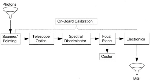
Figure B.1
Depiction of the generic electro-optical sensor.
Since the sizing of scanning mechanisms is driven principally by geometric considerations, technology plays a secondary role in determining size and mass. Technology is certainly a factor in developing lightweight scan mirrors, electromagnetic torquers, and position encoders, but these elements are already well developed and not subject to dramatic improvements. Lightweight beryllium scan mirrors are already in widespread use, for example.
In other cases, specialized performance requirements make it preferable to design sensors with a moving telescope assembly instead of a moving scan mirror. The SeaWiFS (Sea-Viewing Wide Field-of-View Sensor) is designed with a scanning telescope in order to minimize polarization sensitivity and, correspondingly, to maximize the radiometric fidelity of its ocean color measurements.
Still other sensor design approaches dispense with scanning mechanisms altogether by employing wide-field telescope forms. Such designs cannot accommodate more complex telescope optics and detector arrays, but this is often a reasonable trade-off given the current state of technology. Pushbroom designs, utilizing linear detector arrays and optical designs with a moderately wide field of view (~5°) in one dimension, have been in use for some time in sensors such as the French SPOT (Systeme Pour l'Observation de la Terre) satellites; the design remains attractive for high-resolution imaging systems with fields of view to 15°. "Fish-eye" lens designs can be used to provide wider field coverage, but the severe geometric distortion and limited spectral range of such designs usually make them more appropriate for nonimaging applications such as missile launch detection. Pushbroom designs are not suited to moderate-resolution wide-field systems such as MODIS (Moderate-Resolution Imaging Spectrometer) or AVHRR (Advanced Very High Resolution Radiometer), because the extended focal planes of such designs—coupled with relatively short focal lengths—lead to unworkable field angles and geometric distortion problems.
Moving the entire spacecraft with the telescope assembly remaining fixed relative to the body of the spacecraft is yet another scanning alternative, and is particularly suitable for single-sensor small satellites. Here, the
sensor design is simplified because scanning and pointing mechanisms or mirrors are eliminated, with concomitant savings in instrument payload size, cost, and complexity. At the same time, additional demands are placed on the spacecraft's attitude control and determination system, with more stringent requirements for control of angular position and angular velocity. This also requires added spacecraft mass and power, since control moment gyros designed and sized to provide spacecraft agility are heavier and require more power than reaction wheels that are used solely for attitude control.
TELESCOPE OPTICS
The telescope opto-mechanical assembly represents the next major sensor subsystem, and technology certainly plays a role in the size/mass equation after the first-order sizing is established by the immutable laws of diffraction. Specifically, different optical forms and prescriptions vary widely in terms of their packaging efficiency. For a given aperture diameter, effective focal length, and level of performance, optical systems of different designs can differ tremendously in terms of number of optical elements, total mirror area (and hence mass), as well as different fabrication and alignment tolerances. Figure B.2 is a scale drawing that shows three different optical designs for a pushbroom imager with a 15° field of view: Each design has exactly the same first-order properties—i.e., the same aperture diameter and focal length. Yet the overall packaging volume and total mirror area are strikingly different for the three designs. These differences translate directly to sensor size and mass. The effects are further magnified because the layout dimensions and alignment tolerances strongly influence the size and mass of the associated optical metering structure—the structure that holds the optical elements in their required positions with the requisite precision. Most of the remote sensing instruments currently in development or production have exploited advances in optical design techniques in order to minimize size and mass.
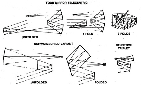
Figure B.2
This scale drawing of different telescope designs, all with the same aperture diameter and focal length, shows striking differences in packaging efficiency. Reflective triplet is most compact.
Besides clever optical design, advanced materials play an important role in offering future mass reductions. Lightweighting techniques are already widely used for both metallic and glass optical elements, and the use of high-stiffness-to-weight-ratio materials, such as graphite-epoxy composite, is the norm for optical metering structures. Further improvement in the materials arena should be of an incremental rather than revolutionary order, however. Silicon-carbide optics hold some promise, for example, but this will not lead to factor-of-two reductions in overall mass for typical EOS sensors.
As discussed above, the physics of diffraction is a key factor that constrains sensor design. However, there are techniques for mitigating the effects of diffraction that may offer some benefits for future high-resolution systems. Specifically, sparse aperture or partial aperture systems can provide diffraction limited performance that is comparable to that of filled aperture systems—albeit at the expense of photon-collecting area and, hence, signal-to-noise ratio. This may be a reasonable trade-off for systems in which resolution is more important than radiometric sensitivity.
As illustrated in Figure B.3, the partially filled aperture system on the right has essentially the same optical cutoff frequency as the full aperture system on the left, but the total mass of the mirrors would be dramatically smaller than a single large optic. Moreover, manufacturing several elements of modest size is less expensive and complex than manufacturing a single large element to exacting tolerances. In the particular case illustrated in the figure, the total mirror area of the sparse aperture system is just half of the conventional design, and the corresponding mass ratio would be even less than the area ratio because the mass has to increase on the order of the cube of the largest linear dimension in order to maintain the same relative stiffness. However, the partial (or multiple) aperture system would require added complexity in mounting and alignment of the additional optical
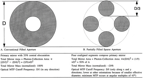
Figure B.3
Sparse aperture designs trade radiometric sensitivity and modulation transfer function (MTF) uniformity for lower mass.
Note: Mass scales approximately as the cube of the maximum linear dimension when designing to maintain approximately constant stiffness.
elements, and this would undermine some of the mass and cost savings. Further, there would be new technical issues in terms of maintaining the relative alignment of the segments, and there are some second order performance issues, such as modulation transfer function nonuniformity as a function of directional orientation.
Even more exotic techniques, such as optical synthetic apertures, can be considered methods for reducing at least the mass and size of telescope optics. Such techniques are clearly in their infancy: While synthetic apertures are practical at microwave frequencies, maintaining phase coherence (or an accurate phase history) is a formidable challenge at optical wavelengths.
SPECTRAL SEPARATION
Spectral separation is the next subsystem technology that is needed en route from photons to bits, and technological advances in this arena can certainly be enabling factors for size/mass reduction, particularly for hyperspectral instruments. For sensors having a relatively small number of spectral bands, multilayer dielectric interference filters remain the spectral separation method of choice. For this ''multispectral" class of sensor, the technology trend has been toward multiple filters located near the focal plane.
As filter packaging techniques have improved, there have been some modest reductions in the volume of the aft optics and focal plane assemblies of these sensors, and some designers have explored direct deposition of spectral filters onto detector arrays. Although this is technically feasible, it is not in widespread use for radiometric instruments because it effectively cascades two complex processes, resulting in lower yields and consequently higher costs; the minor gains in packaging efficiency are generally not worth the added cost and risk. For example,
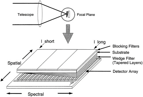
Figure B.4
Wedge spectrometer approach reduces size and mass of hyperspectral sensors.
if detector array processing is a 20-step process with each step having a yield of 0.98, the overall yield for detectors alone would be approximately 0.9820, or 67 percent. If four separate filters each having 40 layers were subsequently deposited on the detector array, the overall yield of the detector assembly would be on the order of 2.6 percent (if the filter deposition yields were also 0.98 per layer).
Advances in filter technology are having very significant impacts on the design of hyperspectral instruments. Historically, hyperspectral spectrometers (i.e., instruments with hundreds of spectral bands) have been built with dispersive optical systems using either prisms or diffraction gratings. Such approaches work well, but they require large and complex reimaging optical systems. In contrast, spectrometers using tapered dielectric filters mounted close to the focal plane can dispense with the complex optics and make it possible to build very simple compact hyperspectral instruments, as illustrated in Figure B.4. While this "wedge spectrometer" design is attractive for many imaging and sounding applications, it is not a panacea: There are performance trade-offs regarding spectral simultaneity and sensitivity that may make conventional spectrometers more suitable for some applications.
FOCAL PLANE DETECTOR TECHNOLOGY
Detector technology can influence some basic sensor design trade-offs and lead to concomitant size and weight reductions. Increasing the number of detector elements can permit reductions in optical aperture size, until aperture size becomes governed by spatial resolution—and not by the optical collecting area required to achieve the requisite radiometric sensitivity. In essence, the availability of integrated high-density detector arrays allows designers to reduce the size of the optics to dimensions that are close to those set by the theoretical diffraction limit.
Technology now permits the design and production of integrated detector arrays that include first-level preamplification and multiplexing as part of the focal plane; this in turn permits simplification of the sensor's other electronic subsystems. For example, the focal plane arrays on the MODIS sensor utilize integral capacitive transimpedance amplifiers to integrate and amplify the detector signals; this eliminates the need for much larger off-focal-plane electronic modules that would otherwise be required to perform that function.
CRYOGENIC COOLERS
The cryogenic subsystems needed for cooling infrared detector arrays (and sometimes optical elements) are another key determinant of size and mass for sensors that extend spectral coverage into mid-to long-wave infrared wavelengths. There are relevant passive and active approaches to cooling. Passive radiative coolers are well developed and provide exceptional reliability. The size of these coolers is, however, governed by the first-order physics of Planck's radiation law. The required minimum area for the radiative surface is governed by the relationship W = AesT4, where W is the radiated power, A is the area of the radiator, e is the effective emissivity of the radiator's surface, s is the Stefan-Boltzmann constant, and T is absolute temperature. This relationship can be expressed as A = W/esT4. Thus, the area of the radiator needed to achieve a given cryogenic temperature depends directly upon the amount of cooling power required and upon the inverse fourth power of temperature. This is a highly nonlinear relationship; for example, it takes four times as much radiator area to reach 60 K as to reach 85 K. Consequently, application of this comparatively straightforward technology is limited to relatively modest levels of cooling power at temperatures of about 65 K or warmer. This is more than adequate for sensors such as MODIS, but passive cooling would be a challenge for a high-resolution pushbroom long-wave infrared imager, for example.
There are other considerations regarding the use of passive radiators. The radiator must be properly oriented and shielded to minimize thermal loading from the Earth, Sun, and spacecraft appendages in order to provide efficient cooling. There are also many technical subtleties in producing passive coolers in order to approach the theoretical minimum size set by Planck's radiation law. For example, control and minimization of parasitic heat loads is something of an art, but is essential to producing efficient radiative coolers.
Active cryogenic refrigerators offer an alternative to passive radiators. Active coolers offer greater capacity and provide additional freedom in packaging and locating the sensor on the spacecraft, since there are no preferred
orientations or constraints on view factors. These benefits are provided at the expense of fairly high power consumption, added mass, and diminished reliability. Indeed, there is a crossover point in size/mass efficiency: Passive coolers tend to be the better choice for modest heat loads (<1W) at temperatures above ~80 K; active coolers become attractive for higher heat loads (>2W) at temperatures of 65 K or colder. There are application specific exceptions to these guidelines, and there is a gray region where the selection is not as clear cut, but the parameters cited above serve as a useful point of departure.
Active cryogenic refrigerators have been under development for many years with significant funding from the Department of Defense. This technology has progressed very well, with space-qualified, life-tested units available from British Aerospace, Hughes Aircraft, and TRW, among others.
ELECTRONICS TECHNOLOGY
Advances in electronics technology probably offer the most broadly and readily applicable avenue for further reductions in the size/mass/cost of space sensors. A substantial fraction of nearly every sensor design is devoted to the electronics that provide preamplification, filtering, analog-to-digital conversion, on-board signal processing, and high-speed multiplexing functions, as well as command, control, telemetry, and conditioned power. Although the size, mass, and power requirements of these electronics have been reduced at an astonishing rate over the past 20 years, such advances are often exploited to enhance functionality or reliability rather than size/mass reductions. And in fact, enhancing on-board processing capability can be a very logical choice from a total system cost standpoint. For example, in applications where a sensor provides a real-time data stream, it is almost certainly less expensive to perform radiometric responsivity correction on board the spacecraft instead of imposing a signal processing burden on each and every ground (or mobile) receiving station.
Even with added on-board functionality, the stunning improvements in electronic device technology hold the promise of significant reductions in size/mass/power requirements—with one caveat. The technological improvements are being driven largely by the commercial telecommunications and computer industries, and the supplier base for radiation-hardened, space-qualified components is, in fact, contracting. Thus, space systems have not been able to exploit fully the state of the art in electronics. Prudent investment in space qualification of commercial parts and direct investment in specific radiation-hardened devices will pay dividends in future size and mass reductions for space instruments.
Advances in electronic packaging technology also portend significant size/mass reductions for space-borne electronics. The migration to surface-mount packaging is already paying off, but next generation high-density multilayer integration techniques promise even more dramatic reductions in size. The essential idea is to move from the two-dimensional packaging approach embodied by circuit boards to three-dimensional packages that effectively stack or laminate multiple layers into a high-density package. This is more challenging than it might at first appear, because high-density packaging raises many technical issues such as thermal management and electromagnetic interference. Moreover, as packaging density increases, there are concerns about testability, repair and maintenance, and reliability—important factors because these "systems in a cube" become very high-value components, thus making the practicality and economics of testing and repair during the manufacturing process very important. Packaging technology is moving toward high-density three-dimensional modules, and the application of such technology to space instruments will have a major impact on overall sensor size and mass.
For example, electronics and their associated housings account for nearly 44 percent of MODIS's total mass. Therefore, as electronic device and packaging technology progress beyond the level embodied in the current MODIS design, retrofit of new electronics would be a highly cost-effective way to reduce the overall mass of the instrument while preserving the substantial nonrecurring design investment in MODIS's opto-mechanical sub-systems, which are already governed more by physics than by technology.
ACTIVE SENSORS
In addition to passive electro-optical sensors, other classes of instruments, such as active optical systems and both active and passive microwave instruments, are of interest to Earth observation, meteorological, and planetary
science missions. Much of the foregoing discussion regarding telescopes, pointing and scanning mechanisms, and electronics technology is equally applicable to both active and passive Earth observation sensors, but the design trade-offs and sizing constraints for active sensors are also heavily influenced by the technology of the active sources themselves—most specifically, lasers. In this regard, the overall "DC to photons" energy conversion efficiency is probably the most important factor in accommodating active Earth observing sensors on small satellites. This technology encompasses everything from high-efficiency solar arrays and DC to DC power converters to the efficiency of the laser devices themselves. These efficiencies vary widely depending on the wavelength of interest, but are typically in the range of a few percent for laser sources that are of interest to space science. The efficiency of the energy conversion process is the fundamental issue that will determine the future feasibility of small satellites to serve as platforms for sensors such as the Laser Atmospheric Wind Sounder.
Similar efficiency issues pertain to active microwave sensors, although there are additional degrees of design freedom wherein transmit power and antenna gain can be traded to achieve equivalent levels of effective isotropic radiated power. As antenna gain (directivity) is increased, transmitted power can be lowered, but the physical size of the antenna must grow proportionately to achieve the higher gain. There is thus a size/mass/power trade-off for active microwave systems. Pointing and scanning design issues comparable to those related to optical instruments are also involved.


