
2
Acquisition Design Package Processes and Modifications
Initial designs for the ADPs of the Aberdeen and Newport facilities were developed by SWEC under supervision by the U.S. Army Program Manager for Chemical Demilitarization (PMCD) (U.S. Army 1998a, 1998b). The selected contractors, Bechtel National, Inc., for the Aberdeen Chemical Agent Disposal Facility (ABCDF), and Parsons Infrastructure and Technology Group for the Newport Chemical Agent Disposal Facility (NECDF), will subsequently procure, install, and operate the facilities. After reviewing the ADPs for their respective sites, both contractors suggested modifications to the processes. The modifications were discussed with SWEC and the PMCD, who will authorize accepted variations.
ABERDEEN CHEMICAL AGENT DISPOSAL FACILITY
The basic component processes in the ADP for the ABCDF (shown in Figure 2-1 ), which were described in Review and Evaluation of Alternative Chemical Disposal Technologies (NRC, 1996a), are listed below:
-
draining of HD from ton containers and removal of the residual agent by a series of hot water and steam sprays
-
neutralization of the HD by hydrolysis using water in a stirred tank at a temperature just below the boiling point, followed by the addition of aqueous sodium hydroxide to neutralize acid formed during hydrolysis
-
removal of VOCs from the resulting hydrolysate by vaporization in a falling film evaporator
-
decomposition of condensed VOCs in an aqueous hydrogen peroxide and sodium hydroxide solution exposed to ultraviolet radiation
-
removal of organic compounds remaining in the hydrolysate (after VOC removal) with a sequencing biological reactor (SBR), using an activated sludge process with added nutrients
The treated hydrolysate and sludge from the SBR flow to an on-site, federally owned treatment works for further biological and physical treatment prior to discharge. The sludge consists of excess biomass produced during the treatment of hydrolysate in the SBR. The excess biomass, which is separated, dewatered, and shipped off site for commercial disposal, is expected to be similar to sludges generated by traditional wastewater treatment processes, which are routinely disposed of in commercial facilities.
Each step of the ABCDF process is decoupled from the other process steps by storage of the product of 24 hours of operation to allow operation with either the preceding or subsequent processing step off line. The draining and decontamination of ton containers and the agent hydrolysis steps are batch processes, and reactors are sized to accommodate the agent from one ton container per batch. The VOC removal system is a continuous operation with significant turn-down capacity to accommodate changes in the rate of hydrolysate production; the VOC removal system is buffered by both upstream and downstream tankage. The biological reactors are also operated in a batch or semibatch mode. Vent gases from tankage that could potentially contain agent are treated by activated carbon before being discharged into the cascade ventilation system of the facility, which is modeled after the ventilation systems at the baseline incineration sites at Tooele, Utah, and Johnson Atoll. In this system, air flows from its highest pressure in nonagent areas to potentially agent-contaminated areas at lower pressure, then to toxic cubicles maintained at still lower pressure prior to being discharged through a series of activated carbon filters. The areas are separated by air locks. Air from areas that will not be exposed to agent (e.g., biological reactors) is exhausted through separate activated carbon filters. The facility is designed to treat six ton containers per day, or 10,000 pounds of agent per day. The plant is scheduled to be operated for nine months during pilot operations and 11 months during full operations.
Bechtel has evaluated various alternative processes for the removal, recovery, and destruction of VOCs at the
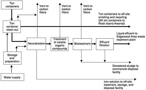
FIGURE 2-1 Basic component processes in the ADP for the ABCDF. Source: Ward, 1999.
ABCDF, including either steam or air stripping of the VOCs from the hydrolysate, followed by VOC recovery on an activated carbon sorbent. In the case of steam stripping, the VOCs are recovered from the liquid phase after condensation of the steam. In the case of air stripping, they are recovered from the gas phase. In both cases, the spent activated carbon is returned to the supplier of the carbon, and the recovered VOCs are destroyed in the process of regenerating the sorbent.
Following a comparison of the complexity, safety, and cost of these treatment processes, including a modification of the process in the ADP, Bechtel recommended that air stripping of VOCs from the hydrolysate be used (Bechtel, 1999). Bechtel's preliminary, revised design includes two packed stripper columns in parallel, followed by three carbon filters in series. The carbon filters recover both VOCs stripped from the hydrolysate and organic compounds in vapors released from the hydrolysate storage tanks. (An overall process description and material throughputs for the ABCDF can be found in Appendix A .)
The modification recommended by Bechtel eliminates the need for steam to heat an evaporator or for stripping; eliminates the need for a condenser and storage tank to provide liquid for the ultraviolet oxidation process; and eliminates the need for hydrogen peroxide to augment ultraviolet oxidation of VOCs. With the revised process, the plant will be safer, more reliable, and less costly. However, the revision does involve a significant change in the overall process flow and creates an additional process stream (i.e., the air flow from the carbon filters). Therefore, the change would require modifications of various permits, which could delay the construction and operation of the plant, although the overall schedule for completing disposal operations is not likely to be affected.
Air stripping has been used in various applications to remove VOCs from water. For example, VOCs similar to those from the ABCDF process streams have been removed from contaminated groundwater by air stripping. At the ABCDF, the stripper will have to remove approximately 99 percent of the VOCs to meet the requirements of the Resource Conservation and Recovery Act (RCRA) for discharge of the aqueous stream. Furthermore, the high entry temperature of the hydrolysate into the air stripper, and the consequent temperature change in the hydrolysate as it flows through the stripper and as the water is vaporized, are design considerations that will have to be addressed.
The quantity of activated carbon required to remove stripped VOCs from the air stream has been estimated to be 600 lb/day (Bechtel, 1999). Frequent change-outs of the activated carbon will be necessary. The design and instrumentation of the filter system should have the following capabilities:
-
handling high loadings of VOCs
-
indicating when fresh filter material is required
-
facilitating the addition of fresh, and the removal of spent, filter material with minimum down time to plant operations
A critical consideration is identifying an off-site waste processor who is able and willing to receive the carbon filter material from the VOC treatment step. A waste processor will certainly require that VOCs be stripped from the hydrolysate only after agent destruction has been confirmed by chemical analysis. Consequently, the spent activated carbon used to recover VOCs should be agent free and can be treated like any other commercially produced spent filter material. If the spent activated carbon cannot be certified as agent free, it will have to be managed in the same manner as spent activated carbon that is known or likely to be agent contaminated.
Recommendation 2-1. The alternative process for the removal, recovery, and disposal of volatile organic compounds (VOCs) recommended by Bechtel, the contractor for Aberdeen Chemical Agent Disposal Facility (ABCDF), using air stripping followed by vapor-phase activated carbon absorption, is an improvement over the VOC removal process described in the acquisition design package and should be incorporated into the final design of the ABCDF. The activated carbon filter system should be designed to sustain high loading and enable rapid change-out of VOC-laden filter material.
NEWPORT CHEMICAL AGENT DISPOSAL FACILITY
The basic component processes in the ADP for the NECDF (shown in Figure 2-2 ), which were described in Review and Evaluation of Alternative Chemical Disposal Technologies (NRC, 1996a), are listed below:
-
neutralization of VX agent by hydrolysis using an aqueous solution of sodium hydroxide in a stirred tank, at a temperature just below the boiling point
-
removal of organic compounds from the resulting hydrolysate by oxidation with pure oxygen by SCWO
-
evaporation of the aqueous stream from the SCWO reactor with a forced-circulation evaporator/crystallizer, followed by condensation of the vapor, crystallization of the inorganic salts from the concentrated liquid, and recovery of the solids
Prior to discharge, the condensate flows to the on-site federally owned treatment works, which includes an activated-sludge sewage treatment plant. The crystallized salts are shipped to an off-site commercial treatment, storage, and disposal facility.
Each step of the NECDF process is decoupled from the other process steps by storage of the product of 24 hours of operation to allow operation with either the preceding or subsequent processing step off line. The draining and decontamination of ton containers and the agent hydrolysis steps are batch processes, and reactors are sized to accommodate the agent from one ton container per batch. The SCWO
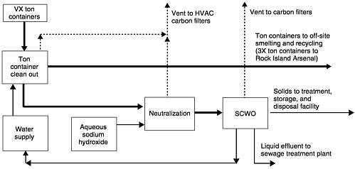
FIGURE 2-2 Basic component processes in the ADP for the NECDF. Source: Ward, 1999
reactor process step includes two processing lines that can be operated either individually or in parallel as continuous processes, with scheduled off-line periods for rinsing the reactor. Tankage is provided both upstream and downstream of the SCWO reactor. Vent gases from tankage that could potentially contain agent are treated by activated carbon before being discharged into the cascade ventilation system of the facility, which is modeled after the ventilation systems at the baseline incineration sites at Tooele, Utah, and Johnston Atoll. In this system, air flows from its highest pressure in nonagent areas to potentially agent-contaminated areas at lower pressure, then to toxic cubicles maintained at still lower pressure prior to being discharged through a series of activated carbon filters. The areas are separated by air locks. Air from areas that will not be exposed to agent (e.g., SCWO effluent gases) is exhausted through separate activated carbon filters. The facility is designed to treat six ton containers per day, or 9,000 pounds of agent per day. The plant is scheduled to be operated for seven months during pilot operations and eight months during full operations.
The contractor, Parsons, is now considering the following alternatives for dealing with the effluent aqueous stream from the SCWO reactor:
-
alternative evaporator/crystallizer designs (e.g., drum drier, spray drier, thin-film evaporator)
-
off-site shipment and disposal of the unconcentrated effluent, eliminating the evaporation, crystallization, and crystal drying processing steps
-
off-site shipment and disposal of a concentrated brine from the evaporator (containing primarily sodium sulfate and sodium phosphate), eliminating the crystallization and crystal drying processing steps
In the meantime, Parsons is seeking public and regulatory approval for the off-site shipment of the dilute effluent from the SCWO reactor and continuing design development of the evaporator/crystallizer included in the ADP. A number of similar evaporator/crystallizer installations have been cited as examples of such equipment (NRC, 1998). Parsons recommends eliminating the evaporator/crystallizer in the NECDF design if shipment of dilute SCWO effluent from the site is approved, which would significantly simplify overall process operations. (A process description and material throughputs for the NECDF is included in Appendix B.)
Recommendation 2-2. The Army should continue to identify and pursue regulatory approval for waste management facilities to receive off-site shipments of brine from the supercritical water oxidation processing of VX hydrolysate at the Newport Chemical Agent Disposal Facility. However, given the modest cost of the equipment and the significant costs and processing delays that could result if shipping or receiving of the effluent were not allowed or became prohibitively expensive, the capability of processing the brine on site should be maintained.
AGENT HOLDING AND PROCESSING
The Aberdeen and Newport ADPs include essentially the same arrangements for handling ton containers (i.e., agent draining, clean out, and preparation for off-site disposal). All processing of ton containers to remove agent is carried out in toxic cubicles designed to contain agent vapors, maintained under negative pressure, and ventilated through a series of activated carbon filters. The design of the toxic cubicles is essentially the same as the design of the cubicles at the Johnston Atoll and Tooele facilities. Operations in the cubicles are carried out by automated machinery operated remotely. The ton container is initially punched in two locations, and the agent is removed through a drain tube. Next, the ton container is cut in half perpendicular to the primary axis. Each half is then subjected to high-pressure hot water and steam sprays to remove residual agent. After treatment, the container halves are transferred through air locks to a holding chamber with atmospheric monitoring to verify that no detectable agent remains. If agent is detected, the container half is returned for further hot water and steam treatment until agent is no longer detected. Personnel are not present in the toxic cubicles during operations. During maintenance and decontamination operations, they must wear protective ensembles specific to the type of agent.
Holding and Processing
The chemical agent holding and processing arrangements for the ABCDF includes three identical processing lines, each of which includes the following components:
-
a chemical agent holding tank and associated surge tank
-
two agent neutralization reactors
-
a holding tank for effluent from the clean-out of ton containers
-
a holding tank for effluent from the decontamination of ton containers
-
a scrubber system, including a condenser and two carbon filters in series, for the neutralization of vent gas
This equipment is housed in one cubicle for each processing line. Drained agent is stored in the same room as the neutralization reactors and other processing equipment.
The plan for holding and processing chemical agent at the NECDF calls for a chemical agent holding tank and associated surge tank, from which agent is fed into two identical neutralization processing lines, each of which includes the following components:
-
a reactor for treating drained agent
-
a reactor for treating effluent from the clean-out of ton containers
-
a holding tank for effluent from the decontamination of ton containers
The agent holding and surge tanks are located in an enclosed toxic cubicle. Each neutralization processing line is located in a separate enclosed cubicle. No vent gas scrubber or carbon filter is located in either of the neutralization cubicles to treat vent gases.
The rationale for differences between the agent holding and processing arrangements at the Aberdeen and Newport facilities is not immediately clear. The ABCDF approach, with its multiple agent holding tanks, increases plant complexity. In addition, because the chemical agent holding and surge tanks are located in the neutralization processing cubicle, rather than in a separate enclosure, a larger area than necessary could be contaminated from an accidental spill. The use of multiple agent holding tanks also differs from currently operating baseline facilities at Tooele, Utah, and Johnston Atoll, both of which have a single agent storage tank in a separate enclosure.
Recommendation 2-3. The Army should conduct a comparative evaluation of the designs for enclosures to store and process chemical agent at the Aberdeen and Newport facilities to determine if similar enclosures could be used for storing and processing drained agent.
COMMINGLING OF PROCESS VENT GASES AND PLANT VENTILATION AIR
At both the ABCDF and NECDF, the plant ventilation air flows through a sequence of enclosed areas. First, air is drawn from the ambient air into areas where agent contamination is least likely. Then, controlled by vents, the air cascades through a sequence of plant areas where contamination is increasingly likely. Upon exiting these areas, the ventilation air passes through an activated carbon filter to remove any traces of agent and VOCs. Drawn by exhaust fans, it then flows back to the ambient air. Thus, the air pressure in the plant is lower than the ambient air pressure and is lowest where agent contamination is most likely. Under normal operating conditions, the airflow and pressure levels in the plant will prevent the migration of agent vapors from contaminated to uncontaminated areas. However, upsets can occur in the plant heating, ventilation, and air conditioning (HVAC) system as a result of the misalignment of doors and dampers, obstructions in ducts, malfunctioning air locks (used to pass objects between areas of the plant), and failures of exhaust fans. Moreover, the ABCDF and NECDF ventilation systems contain parallel flow paths, which are particularly susceptible to upsets.
Process vent gases from agent holding and surge tanks, neutralization reactors, and holding tanks for effluent from the clean-out of ton containers are all likely to contain agent vapors and VOCs, both of which can be removed either by first passing them through a carbon filter or a scrubber. The scrubbed gas can then be directed into the air ventilation duct passing into the ton container cleanout area or exhausted to the HVAC air filtration system. If process vent gases without pretreatment (as currently designed) are piped into the cascade ventilation system, hazardous process gases could potentially flow back into a nontoxic area of the plant as a result of operational error. Therefore, the direct discharge of process vent gases into ventilation air in the cubicle, even after cleaning, should be avoided.
At both the ABCDF and NECDF, the vent gases from the agent holding and surge tanks pass through an activated carbon filter. The discharge is directed to the sump of the cubicle, to prevent liquid agent from being forced from the vents of these tanks through the filter. However, based on the relative sizes of the primary agent holding tanks and the larger agent surge (overflow) tanks, the rationale for this design is unclear. If only vapors flow through the tank vents and the carbon filter, the discharged gases could be directed into the duct of the ventilation air leaving the toxic cubicle. The systems controlling the flow and level of liquid in the agent holding and surge tanks, as well as the vents, should be designed to minimize the possibility of liquid flowing into and through the carbon filter.
At the ABCDF, vent gases from the neutralization reactors and the ton container effluent tanks pass through a scrubber, two carbon filters in series, and a fan, prior to entering the HVAC ducts that exit the three toxic/neutralization cubicles. These exhaust HVAC ducts lead to the final banks of activated carbon filters and to the induced draft fans.
Vent gases from the hydrolysate storage tanks and the SBRs at the ABCDF are vented to a condenser, a knockout drum, two activated carbon filters in series, and an induced draft fan, prior to being discharged to the atmosphere through the plant stack. At the NECDF, the vents of the four hydrolysate storage tanks are directed through a reflux condenser to a common vent cubicle, then to the activated carbon filters and the induced draft fans of the HVAC system, and finally to the plant stack.
However, vent gases from the neutralization reactor for drained agent and the reactor for the effluent from the cleanout of ton containers in the two parallel neutralization cubicles at the NECDF are vented through a condenser to a single process ventilation cubicle. The vent gases then go to the final set of activated carbon filters and the induced draft fans of the HVAC system and then to the plant stack. The committee is concerned that interior plant air could be contaminated at the NECDF because this design includes no carbon filtration or other detoxification of the process tank vent gases before they flow directly into the HVAC exhaust system of the plant, which includes carbon filtration. At the Tooele and Johnston Atoll baseline incineration facilities, process vent gases (incinerator exhaust gases) are not piped into the plant cascade ventilation system at all. Instead, they are handled and treated entirely separately from the processing building's cascade ventilation system.
For the purposes of a quantitative risk assessment (QRA) and hazards evaluation (HE), a thorough analysis will be
required to determine the potential upset conditions for the ventilation systems, as well as to prevent agent migration into uncontaminated areas from changes in ventilation patterns during normal or maintenance operations. The model currently used for QRAs focuses only on concentrations of lethal agent. Dynamic models of the airflows and pressures for the plant ventilation systems at the ABCDF and NECDF could be used to determine agent levels at various locations in the plants during maintenance activities, in the event of power or interlock failures, and for other upset conditions. Comparisons of predicted properties for parallel systems versus single systems would reveal the safest, lowest risk alternative.
Recommendation 2-4. The Army should conduct a detailed analysis of the cascade ventilation system and its performance at both the Aberdeen and Newport facilities to determine the potential for agent migration during normal operations, maintenance, and upset conditions. A formal, structured evaluation should be performed that includes (1) the use of a dynamic model of the ventilation system to determine the migration of both lethal and sublethal agent concentrations and (2) reported instances of agent migration at the Tooele and Johnston Atoll baseline incineration facilities.
USE OF COMMON DESIGNS
In the preceding section, the committee suggested that a common design for the agent holding and processing systems at the ABCDF and NECDF could be used, as well as common designs and equipment selections for other systems. Candidate systems for common design include ton container clean out, activated carbon filtration of ventilation air and process off-gases, and management of nonprocess waste streams (e.g., agent-contaminated activated carbon; disposal of demilitarization protective ensemble suits, hydraulic fluids, hoses, and cleaning materials). The committee believes that an investigation of using common designs and equipment could encourage the contractors completing the ADP designs for the ABCDF and NECDF to share their knowledge and experience of procurement, installation, operational, and maintenance processes. In addition, if common designs and equipment were used, lessons learned at either installation would be pertinent to the other, and spare parts might be shared.
Recommendation 2-5. The design teams for the Aberdeen and Newport facilities, in coordination with the Army, should develop a formal means of sharing design information and developing best practices. Personnel at each facility should be designated and held accountable for facilitating the exchange of design information and lessons learned.
PLANNING CLOSURE OF THE FACILITIES
In addition to the completion of the ADP designs and the construction, operation, and maintenance of the Aberdeen and Newport facilities, the contractors have accepted the responsibility for plant closure, which will require dealing with stored wastes, plant equipment, buildings, and the land on which the facilities are located. The plant closure end point involves defining the condition of the land and whatever building structures and equipment will remain on the site. Closure can be facilitated if the requirements for closure are carefully considered as part of the completed designs. The Army's closure team for the Johnston Atoll facility is now studying the process of closure and has published a draft report, Guide to Closure Planning: Draft, Revision 0 (U.S. Army, 1999a). Many of the lessons learned from the closure of the Johnston Atoll facility should be transferable to the ABCDF and NECDF.
Elected officials, professional planners, the site workforce, local businesses, and the surrounding public all have important stakes in the closure and future uses of the site. Some of the issues the PMCD will have to address with stakeholders are the economic impact of closure, mitigating negative economic impacts, and analyzing options for future land use. Public involvement will be critical to the resolution of these issues, and local governments and residents are likely to have strong feelings and considerable expertise about economic issues and future use.
Recommendation 2-6. The end points for plant closure of the Aberdeen and Newport facilities should be identified (e.g., allowable residual contamination thresholds and possible future uses of the facilities). Plans for plant design, construction, and operation should include plans for facility closure, and reviews of plant designs should include preliminary plans for closure. Public involvement in determining this aspect of plant design should be encouraged.


