
Appendix A
Process Description for the Aberdeen Chemical Agent Disposal Facility
The following excerpt is accompanied by a simplified flow diagram for the ABCDF (Figure A-1 ) and mass balance tables of input and output streams (Table A-1 and Table A-2 ). The numbered streams in Table A-1 and Table A-2 correspond to the numbered diamonds in Figure A-1 (U.S. Army, 1998).
1. HD PROCESS OVERVIEW
The process design consists of the following process modules:
HD Ton Container Cleanout (TCC) - One Unit
Secondary Heat Transfer Fluid Circulation - Three Units
Water Storage - One Unit
Reagent Storage and Preparation - One Unit
Neutralization - Three Units
VOC Treatment - One Unit
Biotreatment - One Unit
Effluent Filtration - One Unit
1.1 HD Ton Container Cleanout (One Unit)
The HD TCC module transfers the ton container contents to the Neutralization module and prepares the ton containers for shipment off-site. Two holes are punched in the ton container (TC), agent is drained from the container and transferred to the Agent Holding Tank in the Neutralization Module. After draining, the container is rinsed with a series of three sprays using hot water to remove residual agent and heel in the container. Each container is the cut in two and washed, inside and out, with hot spray water to achieve an XXX decontamination condition. Each container half is steamed and air dried before monitoring to verify the XXX decontamination condition. The XXX container halves are then bagged and readied for shipment to off-site smelting. The heated spray water make-up is supplied from the Hot Process Water Tank in the Reagent Storage and Preparation Module. Container rinse effluent is sent to the TCC Effluent Tank in the Neutralization Module. Wash water is recycled through the Spray Water Tank. Spray water is monitored for pH and, when required, a portion of the Spray Water Tank contents is purged to the TCC Effluent Tank. TCC vent gases are vented to the TCC vent scrubber where caustic is used to scrub agent vapors and acid vapors from the vent path. Spent scrubber liquor is sent to the TCC Effluent Tank. The ventilation exhaust is sent to a dedicated carbon filter and then to the site cascade ventilation system.
1.2 Secondary Heat Transfer Fluid Circulation Module (Three Units)
The Secondary Heat Transfer Fluid Circulation module meets the heat transfer needs of the processes carried out in the Neutralization module. There are three identical units in the Secondary Heat Transfer Fluid Circulation Module. Each unit serves one of the three identical neutralization unit toxic cubicles. The Secondary Heat Transfer Fluid Circulation Module provides a boundary between toxic systems and the environment and prevents contamination of plant cooling water by toxic process fluids in the event of heat exchanger leaks.
1.3 Water Storage Module (One Unit)
The Water Storage Module stores water for use in the TCC, Reagent Storage and Preparation, Neutralization, Biotreatment, and Effluent Filtration Modules. Process water is received from the plant water supply and is stored in the Process Water Tank.
1.4 Reagent Storage and Preparation Module (One Unit)
The Reagent Storage and Preparation Module heats process water for use in the TCC and Neutralization Modules, stores sodium hydroxide for use in the neutralization reaction, and dilutes and stores sodium hydroxide for decontamination uses.
Cold process water is received from the Water Storage Module. Eighteen percent sodium hydroxide is delivered by truck and stored undiluted for use in the neutralization reaction.
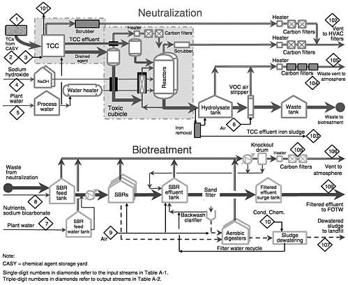
FIGURE A-1 Simplified flow diagram for the ABCDF. Source: U.S. Army, 1998.
1.5 Neutralization Module (Three Units)
The Neutralization Module accepts the ton container contents from the TCC module and destroys the agent batchwise through hydrolysis with water followed by caustic addition. The Neutralization Module consists of three units, each located inside a Containment Level A toxic cubicle. There are two HD Reactors and one TCC Effluent Tank in each of the three neutralization units. In each neutralization unit, drained agent held in the Agent Holding Tank is processed in batch neutralization reactions. The rinse and spray water from the TCC Module and spent decontamination solution are stored in the TCC Effluent Tank and process in separate batch reactions. In the neutralization reaction HD reacts with water to yield the principal hydrolysis products of thiodiglycol and hydrochloric acid. After the hydrolysis is complete and sample analysis results confirm the destruction of HD, 18 percent sodium hydroxide is added to the reactor to raise pH in order to increase the hydrolysate biodegradability. The hydrolysate is then pumped to the Hydrolysate Tank in the VOC Treatment Module.
The vent streams from the HD reactors and the TCC Effluent Tank are combined, scrubbed with a sodium hydroxide scrubber, condensed and passed through dedicated carbon filters before entering the site cascade ventilation system.
1.6 VOC Treatment Module (One Unit)
The VOC Treatment Module is designed to reduce VOC sufficiently to avoid producing Biotreatment sludge that would be a hazardous waste.
The VOC Treatment Module consists of two air stripping units and three portable carbon filter units. One air stripper is in use and the other is on standby or being cleaned. Hydrolysate from the Hydrolysate Tank is cooled to reduce temperature in the carbon beds before being fed to the air stripper. After air stripping the hydrolysate is stored in the Waste Tank for transfer to the Biotreatment Module. The VOC laden air stream from the air stripper is passed through three carbon beds to remove the VOC before the air stream is vented to the atmosphere. The carbon filters are recycled to the portable carbon filter unit vendor for regeneration.
TABLE A-1 Process Inputs for HD/Water Neutralization with Biodegradation
|
TCC Clean-out, Neutralization, and VOC Air Stripping |
Biodegradation |
||||||||||
|
Stream Number |
1 |
2 |
3 |
4 |
5 |
6 |
7 |
8 |
9 |
10 |
|
|
Description |
TCs with Agent |
TCC Air |
TCC Steam |
Neutral NaOH (aq) |
Neutral Water |
VOC Air Stripper |
Biodegradation Water |
Nutrients and Buffer |
Air |
Conditioning Chemicals |
Total Inputs |
|
Total flow (kg/1,000 kg) Pressure (psig) |
1,000.00 |
1,152 |
234 125 |
262 |
24,066 |
4,261 |
58,770 |
1,039 |
68,310 |
72 |
159,166 |
|
Temperature (°F) Physical state |
70 |
70 |
351 |
70 |
70 |
70 |
70 |
70 |
70 |
70 |
|
|
(solid (S), liquid (L), gas (G)) |
S,G & L |
G |
G |
L |
L |
G |
L |
S & L |
G |
L |
|
|
Components HD |
828.00 |
828 |
|||||||||
|
Sodium hydroxide Water |
6 |
234 |
215 |
47 24,066 |
21 |
58,770 |
342 |
52 |
47 83,706 |
||
|
Sulfur containing impurities |
131.00 |
131 |
|||||||||
|
Chlorinated aliphatic |
6.00 |
6 |
|||||||||
|
NaHCO3 |
963 |
963 |
|||||||||
|
KNO3 KCl |
14 |
14 |
|||||||||
|
Na2SO4 NH3 |
35 |
35 |
|||||||||
|
Na3PO4 Wolin salts |
8 |
8 |
|||||||||
|
H3PO4 Organics |
19 |
19 |
|||||||||
|
Polymer Iron chlorides |
35.00 |
4 |
4 35 |
||||||||
|
O2 N2 |
266 879 |
985 3,253 |
15,797 52,140 |
17,048 56,272 |
|||||||
|
CO2 |
1 |
2 |
31 |
34 |
|||||||
|
Biosolids |
|||||||||||
|
Fe(OH)3 Activated carbon |
16 |
16 |
|||||||||
|
(66 kg Estimated) |
|||||||||||
|
TC shells (No./1,000 kg) |
1.23 |
||||||||||
|
TC valves (No./1,000 kg) |
2.49 |
||||||||||
|
TC plugs (No./1,000 kg) |
7.45 |
||||||||||
|
TC cuttings |
|||||||||||
|
(3 lb./TC estimated) |
|||||||||||
1.7 Biotreatment Module (One Unit)
The Biotreatment Module is designed to biologically degrade thiodiglycol and other compounds in the stripped hydrolysate using sequencing batch reactors (SBRs).
The stripped hydrolysate is transferred from the Waste Tank in the VOC Treatment Module to the SBR Feed Tank. Nutrients are added, the pH is adjusted and the hydrolysate is diluted with water in preparation for the transfer to the SBRs. Sodium bicarbonate solution is added to the SBRs to neutralize the acids formed during biotreatment and to maintain pH. Biodegradation of the organics in the stripped hydrolysate produces carbon dioxide, water, biomass
(sludge), and salt. Sludge, which is settled and withdrawn daily from the SBRs, is biologically stabilized in aerobic digesters and then thickened and dewatered prior to disposal. The supernatant from the SBRs is pumped to the Effluent Filtration Module. Vent gases from the aerated tanks in the Biotreatment Module are passed through carbon filters prior to their release to the atmosphere.
TABLE A-2 Process Outputs for HD/Water Neutralization with Biodegradation
|
TCC Clean-out, Neutralization, and VOC Air Stripping |
Biodegradation |
||||||||||
|
Stream Number |
101 |
102 |
103 |
104 |
105 |
106 |
107 |
108 |
109 |
||
|
Description |
TC Metals |
Vent Gas |
Iron Clarifier Sludge |
Activated Carbon |
VOC Stripper Vent |
Vent Gas |
Biomass |
Activated Carbon |
Water Effluent |
Total Outputs |
|
|
Total flow (kg/1,000 kg) Pressure (psig) |
1,152 |
964 |
67 |
4,261 |
68,876 |
894 |
4 |
83,014 |
159,232 |
||
|
Temperature (°F) Physical state (solid (S), |
70 |
110 |
90 |
70 |
140 |
100 |
90 |
70 |
93 |
||
|
liquid (L), gas (G)) |
S |
G |
L |
S |
G |
G |
S |
S |
L |
||
|
Components TDG |
8 |
8 |
|||||||||
|
Sodium hydroxide Water |
6 |
875 |
21 |
689 |
695 |
81,467 |
83,753 |
||||
|
Sulfur containing impurities Chlorinated aliphatic |
28 |
28 |
|||||||||
|
hydrocarbons |
5 |
5 |
|||||||||
|
NaCl NaNO3 |
34 |
5 |
671 29 |
710 29 |
|||||||
|
NaNO2 KNO3 |
8 2 |
8 2 |
|||||||||
|
KCl |
7 |
7 |
|||||||||
|
Na2SO4 NH3 |
5 |
746 |
751 |
||||||||
|
Na3PO4 Wolin salts |
7 8 |
7 8 |
|||||||||
|
H3PO4 Organics |
1 |
69 |
70 |
||||||||
|
Polymer Iron chlorides |
19 |
4 |
4 19 |
||||||||
|
O2 N2 |
266 879 |
985 3,253 |
14,907 52,212 |
16,158 56,344 |
|||||||
|
CO2 |
1 |
2 |
1,068 |
1,071 |
|||||||
|
Biosolids |
168 |
168 |
|||||||||
|
Fe(OH)3 Activated carbon (estimated) |
62 |
16 4 |
16 66 |
||||||||
|
TC shells (No./1,000 kg) |
1.23 |
||||||||||
|
TC valves (No./1,000 kg) |
2.49 |
||||||||||
|
TC plugs (No./1,000 kg) |
7.45 |
||||||||||
|
TC cuttings |
|||||||||||
|
(3 lb./TC estimated) |
|||||||||||
1.8 Effluent Filtration Module (One)
The Effluent Filtration Module removes most of the remaining suspended solids from the SBR supernatant in the Continuous Backwash Sand Filter. The filter effluent is stored in the Filtered Effluent Surge Tank for transfer to the Federally Owned Treatment Works.
SUPPLEMENTAL INFORMATION
Modification of the Treatment Steps for Volatile Organic Compounds
In the original acquisition design package (ADP), the volatile organic compound (VOC) stream was processed by wetted-wall evaporation followed by hydrogen peroxide mediated ultraviolet irradiation and liquid-phase carbon adsorption (shown in Figure A-2 ). However, this process was subsequently replaced by a simpler, cheaper process—air stripping followed by gas-phase carbon adsorption (shown in Figure A-3 ). VOC treatment facilities are located in the process auxiliary building.
Biotreatment
The biotreatment plant is designed to operate 24 hours per day, seven days per week, and to handle hydrolysate from 7,000 pounds of agent per day. The design throughput is less than the overall plant design capacity of 10,000 lbs of agent per day, which means the biotreatment plant can handle the effluent from the neutralization section only if the latter is operated five days per week, or at 70 percent of capacity. The four sections of the biotreatment plant are described below.
In the feed preparation section, the air-stripped hydrolysate is biotreated so it can eventually be handled in the same federally owned treatment works (FOTW) that handles other wastes from Aberdeen Proving Ground. Nutrients are added to the hydrolysate to promote biological growth in the reactors; sodium bicarbonate is added as a buffer to keep the reaction mixture from acidifying. Aqueous ammonia, phosphoric acid, potassium chloride, and other nutrients are then added. The sequencing biological reactor (SBR) feed is diluted to a concentration of 1 volume percent, the maximum concentration of organics or salts that can be treated in the reactors.
In the SBRs, the soluble organics in the hydrolysate are converted to a mixture of insoluble biomass (that can be settled and separated), water, and carbon dioxide. The ADP calls for three parallel SBR systems to ensure flexibility for low or high feed rates. Each SBR system has its own aeration system. The design criteria call for a hydraulic retention
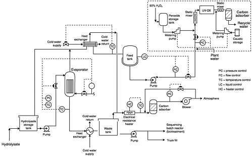
FIGURE A-2 ADP VOC treatment system, wetted-wall evaporation followed by ultraviolet radiation and liquid-phase carbon adsorption.
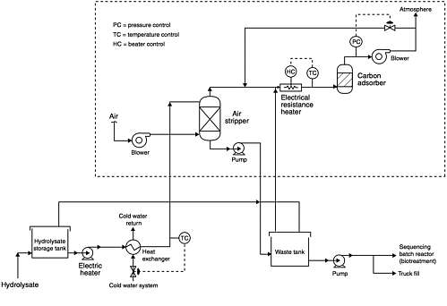
FIGURE A-3 Current VOC treatment system, air stripping followed by gas-phase carbon adsorption. Source: Myler, 1999.
time of 10 days, a solid retention time of 15 days, and a mixed-liquor suspended-solids concentration of 4,000 mg/ liter.
Aerobic digestion reduces the amount of solids generated, as well as the odors produced in sludge-handling facilities. Aerobic digestion can also be a source of biomass to seed the SBRs. The design basis is for a 10-day residence time, which should meet the standards of the Environmental Protection Agency for a specific oxygen consumption of less than 1.5 mg oxygen/gm of suspended solids per hour.
In the sludge-thickening and dewatering section, polymer is added to thicken the sludge from 1 percent total suspended solids content to about 3 percent. Ferric chloride and diatomaceous earth are then added, prior to dewatering in conventional filter presses. The filter cake will have a total solids content of about 20 percent, which is high enough that no free liquids will be present.
Filtration of Effluent
A continuously backwashed sand filter is provided to remove 90 percent of the suspended solids in the supernatant liquids from the SBRs and the filtrates from the thickener and filter press. The filtered effluent is discharged to the FOTW via truck or pipeline. The settled solids are recycled to the aerobic digesters.
Waste Streams
The process produces three waste streams—air emissions, wastewater, and solid waste.
Air Emissions
Four gaseous process streams are vented to the atmosphere: (1) gases from the toxic ventilation system handling exhaust from the toxic cubicles, (2) gases from a similar ventilation system treating exhaust from the clean-out of ton containers (TCC), (3) gases from a separate ventilation system for the VOC system, and (4) gases from a fourth ventilation system that processes biotreatment off-gas. To remove any traces of agent, the gas from the toxic cubicles is scrubbed with caustic soda before it passes through carbon filters and into the atmosphere. The TCC system is similar.
TABLE A-3 Volume of Off-Gas
|
Source |
Standard Cubic Feet per Minute |
|
|
Toxic cubicles |
84 |
|
|
Ton container clean-out (TCC) |
6,000 |
|
|
VOC treatment (with ultraviolet treatment step) |
88 |
|
|
Biotreatment |
5,406 |
|
|
Source: Adapted from U.S. Army, 1998. |
||
Air stripper off-gas from the VOC system in the process auxiliary building is passed through carbon filters. The gases from the biotreatment plant also pass through deep-bed carbon filters. The amounts of off-gas handled by these four systems in standard cubic feet per minute (scfm) are shown in Table A-3 .
In addition, nonprocess air emissions are produced by three boilers, two diesel-driven auxiliary generators, a laboratory filter vent, the medical decontamination area, and a vent from the sodium bicarbonate storage tank.
Wastewater
Wastewater from sumps in each toxic cubicle is treated with caustic and then handled as hydrolysate. The 9,540 lbs/ day of bottom deposits from the hydrolysate clarifier is a slurry of solids that is hauled to an off-site hazardous waste treatment facility. The 581,000 lbs/day of effluent from the effluent filtration module is sent by pipeline to the Aberdeen FOTW (U.S. Army, 1998).
Nonprocess wastewater is discharged directly into the existing system at Aberdeen Proving Ground. However, all wastewater from the utility areas is passed through an oilwater separator before being discharged. Sanitary waste-water is handled in the normal treatment system.
Solid Waste
Decontaminated ton containers are sent to the Rock Island Arsenal for smelting and reclamation. The 6,260 lbs/day of biosolids filter cake is sent to an off-site disposal facility. Spent activated carbon from the various filters, estimated to be generated at a rate of 600 lbs/day, will be tested for 3X surety and sent to the same contractor that takes other carbon filter material from facilities at Aberdeen Proving Ground. Demilitarization protective ensembles, which are at the 3X level after normal decontamination procedures, will be placed in 55 gallon drums, stored in a solid waste storage area, and then shipped off site.
REFERENCES
Myler, C. 1999 . Aberdeen Chemical Demilitarization Facility . Briefing by Craig Myler, Bechtel National, Inc., to the Committee on Review and Evaluation of the Army Chemical Stockpile Disposal Program, Office of the Product Manager for Alternative Technologies and Approaches, Aberdeen Proving Ground, Maryland, July
U.S. Army. 1998 . Acquisition Design Package for the Aberdeen Chemical Agent Disposal Facility. May 1998 . CD-ROM prepared by Stone and Webster Engineering Corporation for the Department of the Army . Aberdeen Proving Ground, Md. : Office of the Product Manager for Alternative Technologies and Approaches .


