
Seafloor Observatory Architecture: Technical Requirements
The principal characteristic of a seafloor observatory, whether it is a moored-buoy or cabled system, is a two-way communication link between instruments and shore. At present, there are two ways to provide this connection: using either a riser or acoustic link from the seafloor to a surface buoy that communicates via satellite or radio to shore, or using a submarine cable linked directly to a shore station.
The following sections outline the characteristics of moored-buoy and cabled observatories, and discuss their current level of technological development. Individual nodes established for various scientific purposes will differ in size, complexity, scientific instrumentation, and technical capabilities in order to balance overall network objectives and cost. This range in the capabilities of individual nodes will permit a measured growth path for the network as a whole. It is envisioned that at the start of an observatory program simpler nodes would be established, with more complex configurations being added when technically feasible. Such an approach will enable the use of knowledge gained from earlier nodes to enhance the later . In addition, at the outset of any observatory program, there is likely to be a trade-off between cost and truly global coverage for certain scientific issues. It is important to note that this chapter and the following discuss current and future capabilities and needs related to seafloor observatory infrastructure. The actual designs that would be implemented must be driven by science needs.
MOORED-BUOY OBSERVATORIES
Moored-buoy observatories consist of a surface buoy acting as a central instrument and communications node, with a satellite or direct radio link to
shore. This surface buoy is mechanically connected to the seafloor and communicates with instrument packages on the mooring line acoustically or via an electrical or fiber-optic cable. Instruments and observatory devices are either directly connected to the seafloor node of the mooring or communicate via an acoustic communication link. The mooring may or may not supply power to peripheral instruments. This class of observatory system draws heavily on several decades of mooring development and the rapid evolution of satellite communications to provide connectivity from shore to instruments in most ocean regions. In contrast to cabled observatories (discussed below), moored-buoy systems are generally less expensive to install, but the trade-off is a greatly diminished communications bandwidth and reduced power availability.
A wide range of sizes and capabilities can be envisioned for the central mooring. The dominant influences on size are the magnitude of power and communications capabilities needed (Table 3-1). A single mooring design cannot satisfy all science requirements. It is possible, however, to group science requirements into those demanding a large central mooring capable of supplying substantial power (>100 W continuous) or relatively high data rates (>100 Mb/day), and those that can be satisfied with smaller, cheaper moorings, which could be deployed singly or in arrays to provide nested-grid spatial coverage of areas of interest. Smaller moorings are also motivated by a desire to obtain rapid event response (within weeks or months). These relocatable systems might provide a few tens of W of power and support data rates of a few megabytes per day (although not necessarily with continuous data transmission).
Data transfer rate, power consumption, and system stabilization requirements are all interlinked, but it is possible to obtain high data-transfer rates at a relatively modest cost provided compromises are made in power and buoy stability. Some satellite systems, because of the need to use a directional antenna, impose strict stability requirements on the surface buoy (<10 degrees per second in pitch, roll, and yaw). Satellite communications can also consume substantial power. As a result, significant amounts of energy will need to be stored within power sources on the mooring. It is difficult at this stage to make specific recommendations with regard to rapid advancements currently taking place in global digital communications. At present, extremely capable satellite communications systems are under development; however, the success of these ventures is far from certain, as demonstrated by the bankruptcy of the Iridium network.1
Data transfer requirements range from less than 1 kb/s to as high as 100 kb/s. In order to prevent disruption to the time-series datasets being collected at a moored-buoy observatory, a backup communications system should be included in the design. Furthermore, the moored system must be capable of storing data onboard if the communications systems were to fail.
|
1 |
Iridium was the first global satellite network for telecommunications. Its 66 crosslinked Low Earth Orbit (LEO) satellites formed a worldwide grid 780 km (485 miles) above Earth. |
TABLE 3-1 Power Consumption Versus Bandwidth Requirements for Selected Observatory Instruments
|
High Power (> 100 W) |
Low Power (< 100 W) |
|
|
High Bandwidth |
Lighting for Photography Imaging/mapping autonomous underwater vehicle (AUV) |
Video Photography Hydrophone arrays Seismometer |
|
Low Bandwidth |
Water Column mapping AUV Acoustic Thermometry of Ocean Climate (ATOC) source Freezer |
Temperature Conductivity Magnetometer Seafloor geodesy Improved Meteorological (IMET) sensors |
During symposium discussions, it was assumed that, to keep power requirements low, simpler re-deployable moorings used for rapid event response and habitat studies will not include Acoustic Thermometry of Ocean Climate (ATOC) sound sources, hydrophone arrays, or video. Although video capabilities are desirable for habitat studies, there are practical limitations to providing the necessary communication bandwidth. For re-deployable moorings with AUV capabilities, power requirements are estimated to be 100 W. Without an AUV, power requirements are estimated to be less than 50 W, which is a level achievable using solar panels. Backup battery power will also be required for instrumentation to ensure continued data collection in case of a power failure. Significant advances in power and satellite communications systems will increase the potential capabilities of the low-cost, relocatable moorings.
Moored-buoy systems will need to be engineered for deployment in varied environments, including those at high latitudes. Deployment location will greatly impact mooring design due to variations in sea state, wind velocity, ocean and air temperature, water depth, and satellite communications coverage. Furthermore, consideration must also be given to other factors, such as the suitability of solar panels in high latitudes, potential for vandalism, and visibility of the mooring in shipping lanes. Some scientific requirements may demand an array of deployable moorings spaced between 500 m and 10 km apart, although care must be taken that the minimum spacing between moorings is less than the watch circle of an individual mooring that is itself dependent on water depth.
The establishment of a moored-buoy site will provide capabilities far beyond those of instruments statically connected to the observatory node. For
example, the ability to vertically profile physical and chemical parameters in the water column is important for many oceanographic studies. This capability can be provided by placing the vertical profiler on a mooring. While science problems require profiling the entire water column, many others will focus solely on the near-surface region. Furthermore, many scientific problems outlined in Chapter 2 will require the use of AUVs to sample between moorings and throughout the water column. A moored-buoy system can provide a docking facility for AUVs, where data can be downloaded and batteries recharged.
It is estimated that the average maintenance interval for a moored-buoy observatory will be every 6-12 months. This maintenance will require approximately one week of University-National Oceanographic Laboratory System (UNOLS) ship time in addition to transit time. ROV capabilities are also likely to be needed for observatory . The assessment of specific impacts on the UNOLS fleet arising from observatory maintenance requirements was beyond the capabilities of this committee. The committee believes that data collection capabilities provided by observatories may, however, reduce the demand for ship time and offset the additional time needed for mooring maintenance.
CURRENTLY AVAILABLE TECHNOLOGY
Small Moorings—The oceanographic community has extensive experience with simple moored-buoy systems deployed to acquire long-duration meteorological and oceanographic data (for example, the Woods Hole Oceanographic Institution [WHOI] alone has deployed on the order of 1,000 such systems). These buoy systems fall into two broad categories: surface-following and surface-decoupled systems, depending on whether the surface float closely follows the sea-surface wave motion or whether it is substantially decoupled from this motion. The former systems include disk, boat hull, and toroid-shaped floats; the latter systems include large spar-shaped floats and subsurface moorings. The mooring systems for either category may be single- or multi-leg, but disk buoys have generally been moored with single-point moorings while large spars have often been moored with multi-leg systems. Within the oceanographic community, disk-buoy systems are far more common than spar-buoy systems. The 3 m aluminum disk buoy, developed at WHOI in the early 1980s, has proven rugged and reliable and has been deployed in experiments of up to 2 years at various locations. In the 1990s, the S-tether mooring was developed to provide a platform for the deployment of subsurface instrumentation that needs to be decoupled from the motion of the surface disk buoy. This mooring system is now operational and has been deployed in the Mediterranean and Labrador seas. Moorings with risers capable of supporting power and communication from the seafloor to surface are recent
developments, and there have been difficulties making them reliable. Data transfer in a vertical channel from the seafloor to the surface buoy for small moorings is currently provided by acoustic modems that are capable of communication rates of up to 5,000 b/s.
Large Moorings—Large, commercial moored-buoy systems, typically spar buoys, have been in use largely for offshore oil production for some time. The commercial moored-buoy system nearest in capability to high-end requirements identified for an oceanographic observatory network is the OceanNet system recently developed by Maritime Communications Services, a division of Harris Electronics Systems (Figure 3-1). The OceanNet buoy is a 10 m high, large discus buoy that is 5.2 m in diameter and weighs ~110,000 lbs. fully loaded with fuel. This buoy uses a single-point mooring and is equipped with a diesel generator to provide 20 kW peak power and a C-band array of mechanically steered antenna elements capable of telemetry rates of up to 2.2 Mb/s using a commercial INTELSAT satellite. The first OceanNet buoy was deployed in the “Tongue of the Ocean,” Bahamas, in 1999 (this buoy sank in a hurricane after 6 weeks on station); a second system is planned for deployment in the Persian Gulf in 2000.
Satellite Communications for Moored-Buoy Systems—At present, the civilian oceanographic community is dependent on commercial satellite communication systems; these systems are described in Chapter 4, in the section titled “Technological Advances in Data Telemetry Technology.”
FUTURE DEVELOPMENTS NEEDED
Although much of the technology needed to establish a network of moored observatories already exists, additional developments and enhancements will be needed. For example, communication systems will benefit greatly from planned advances in low Earth orbit satellite systems. Technology enhancements are also expected in the areas of in situ sensor development, data management, and mooring-riser design. To efficiently incorporate technological developments into moored-buoy systems before deployment in remote locations, an easily accessible testing node will be beneficial.
There are several significant development questions that must be addressed before moored-buoy systems can be routinely used as seafloor observatories:
-
What are the optimal designs of moored-buoy systems—spar or disk, or some hybrid, such as a spar with a single, S-tether mooring?
-
What is the survivability of small spar- or disk-buoy moorings under harsh environmental conditions?
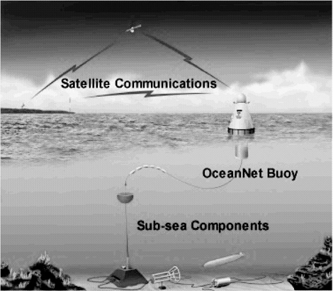
FIGURE 3-1 Diagram of an OceanNet buoy system (MCS, 2000). This system was developed by Maritime Communications Services and consists of deep, shallow, and coastal buoys equipped with satellite communications terminals connected to subsea junction boxes via fiber-optic riser infrastructures that allow direct delivery of data collected. The high performance satellite terminal provides 1 Mb/s throughput and the tuned buoy design allows operation in sea state 6 conditions with a seven-month fuel supply. OceanNet buoys can be deployed in water depths > 3,000 m and can provide global forwarding of data from ocean sensors, custom subsea component interfaces, mission planning and deployment assistance, real-time data collection, autonomous operation, and remote and autonomous command and control.
-
How should power and data be delivered between the seafloor and the buoy—fiber-optic or copper-conductor electromechanical cable? How this cable be protected at critical stress points, for example, near the seafloor and near the surface?
-
How far must the junction box be offset from the mooring to allow servicing by a submersible or remotely operated vehicle (ROV)?
-
What are the stability and power requirements for satellite data telemetry likely to be in 2-3 years as new satellite communications systems come online?
-
What are the expected costs for construction, operation, and maintenance of a moored-buoy, seafloor observatory system? Can UNOLS vessels be used for deployment and maintenance or will specialized vessels be required?
-
What are the design, packaging, and transportation arrangements for a rapidly deployed buoy?
CABLED OBSERVATORIES
Cabled seafloor observatories will use undersea telecommunication cables to supply power, communications, and command and control capabilities to scientific monitoring equipment at nodes along the cabled system. Each node could support a range of devices that may include an AUV docking station.
The major components of a cabled observatory will be
-
shore stations containing high-power and -voltage, direct-current (DC) generation, network management, and science-experiment management equipment;
-
undersea cables containing optical fibers and a power conductor that interconnect shore stations and undersea nodes;
-
undersea observatory nodes containing power conditioning, network management, science-experiment management, and standardized science-experiment interfacing equipment;
-
network and science-experiment command and control and communications systems;
-
specific science-experiment sensors and AUVs.
The requirements of such an observatory include the following:
-
Power—The power required for a cabled observatory network is greatly dependent on the number of high-energy usage devices, such as lamps, pumps, freezers, and scanners, and is anticipated to range between 2-20 kW per node.
-
Data Transfer Rate—The communications requirement for a cabled network depends primarily on the use of video transmission and is anticipated to be, at most, less than 1 Gb/s per node.
-
Ships and ROVs—A commercial cable-laying ship and associated equipment will be needed to install most of the cable, to bury the necessary sections, and to repair cable failures. For operation and most mainte
-
nance purposes, one to two dedicated research vessels or workboats with ROVs will be required to support an observatory consisting of some two dozen nodes.
CURRENTLY AVAILABLE TECHNOLOGY
Cable—The current generation of commercial optical undersea cables can satisfy all anticipated observatory data requirements. These cables contain up to eight or a few dozen optical-fiber pairs for long (greater than approximately 300 km) and short systems, respectively, and can provide data transfer rates on the order of 500 Gb/s per fiber pair. Early-generation, commercial cable systems that may soon be retired have a total cable capacity of approximately 500 Mb/s to 2 Gb/s. Such cables can meet many observatory data needs, but it is not clear that they are suitably located or that power capabilities will be sufficient.
Connectors—Undersea mateable connectors suitable for providing electrical connections between the nodes and specific science-experiment equipment are currently available.
Installation and Maintenance Technology—Currently, ships and ROVs that are suitable for installation and maintenance of cabled observatories exist within industry and UNOLS. Although it is likely that UNOLS ship capabilities would be adequate for many maintenance tasks, the additional burden on the already stressed ROV fleet will need to be addressed.
FUTURE DEVELOPMENTS NEEDED
Physical Design of the Cabled Observatory Nodes—Substantial engineering development will be required for the design and packaging of the power conditioning, network management, and science-experiment management equipment to be placed at the observatory nodes. An important component of this development is the design of the thermal management system required due to the relatively high internal power dissipation. In order to meet the necessary specification for high system-operational time (versus downtime), low repair costs, and overall equipment lifetime, significant trade-offs will have to be considered between the use of commercially available and custom-built equipment.
Sensor, Power, and AUV and ROV Technology—The capabilities needed for sensors, power, and AUV and ROV technology are discussed in Chapter 4.


