
X-Ray Backscatter Advanced
Imaging Technology
The X-ray backscatter advanced imaging technology (AIT) system is based on the backscatter imaging device described by Steven W. Smith in 1991.1 In summary, a well-collimated pencil-beam of X rays is raster scanned across an area in which a person is positioned, and the X rays backscattered from a person toward the source are collected by large area detectors adjacent to and on the side of the X-ray source. The spatial resolution of the X-ray backscattered image is defined by the source collimator aperture and distance from the person to the source; the resolution is not defined by the detector.
Since the technology was first developed, X-ray backscatter AIT systems have evolved, and several models with distinct characteristics are available today. For example, there are at least three X-ray backscatter manufacturers: Rapiscan Systems, American Science and Engineering, Inc. (AS&E), and Tek84 Engineering Group, LLC. Each of these manufacturers produces a “general use” X-ray security screening AIT system.2 The manufacturers use similar physics and differ only in their implementation of the physics and other aspects, as described in the sections below.
_______________
1 Steven W. Smith, X-ray Backscatter Detection System, U.S. Patent 5181234, filed May 22, 1991, and issued January 19, 1993.
2 The term general use systems was introduced by the National Council on Radiation Protection and Measurements (NCRP, 2003, “Screening of Humans for Security Purposes Using Ionizing Radiation Scanning Systems,” Commentary No. 16, Bethesda, Md.) to describe X-ray security screening machines that expose the individuals being screened to a very low dose of radiation and, therefore, there is overall no need to limit the number of individuals screened or the number of screenings an individual can have in a year. This is in contrast to the second category of X-ray security screening
There are two different Rapiscan Secure 1000 configurations: the first configuration uses a single X-ray source and a large area detector in a single housing and acquires data from a single side of a person, either anterior or posterior. Obtaining both anterior and posterior views requires the individual to pose twice, once facing the AIT system and once facing away, leading to what is called a dual-pose AIT system. The second configuration consists of two units facing each other, often referred to as “anterior” and “posterior” units. The two (front and back) sides of the person are scanned in succession. This equipment is referred to as a single-pose AIT system because the person does not have to turn to be scanned both front and back. Screening starts when an operator presses a start button on the anterior unit; the anterior unit scans the anterior of the person being screened, and after the anterior unit is done, the posterior unit scans the posterior of the person being screened.
The anterior and posterior units of the single-pose system take approximately 3 seconds each, and because scanning is performed sequentially, one screening (consisting of two scans) takes a total of about 6 seconds to complete. The dual-pose AIT system requires time for the person being screened to turn around for the second scan and thus takes longer than a single-pose AIT system does. The person being screened using a dual-pose AIT system is not subjected to twice the X-ray dose compared to the single-pose AIT system; they are receiving approximately half the X-ray dose for each of the poses for a total dose equivalent to that from the single-pose AIT system. The actual anterior and posterior doses are given in Chapter 7. The single-pose AIT system (Rapiscan Secure 1000 single pose) was predominantly deployed by TSA until it was removed in May 2013.
Each Rapiscan 1000 unit contains a tungsten anode X-ray tube that operates at a voltage of 50 kV and 5 mA. In the Secure 1000, the X-ray cone-beam emitted by the source is initially collimated by a slit (see Figure 3.1).
Downstream from the slit is a rotating chopper wheel with four equally spaced radial slits that go from near the center to the periphery of the wheel (see Figure 3.1); this is called a rotating geometry. The overlap of a stationary radial slit wheel aperture and the slit aperture results in a pencil beam at the center of the Secure 1000
_______________
systems defined by NCRP Commentary No. 16, named limited use. Limited use systems such as transmission X-ray systems expose individuals being screened to higher doses of radiation that penetrate the body in order to detect objects that have been swallowed or are hidden in cavities. NCRP recommends that these systems be used with consideration of the number of individuals screened and the number of screens per individual in a year. The basic criterion for distinguishing between the two categories is an effective dose of 250 nSv (or less) per screening. Both general use and limited use systems should meet the recommended administrative control for a member of the public of 250,000 nSv (or less) effective dose per year for a single source or set of sources under the control of one entity (committee communication with David Schauer, NCRP, January 15, 2014).
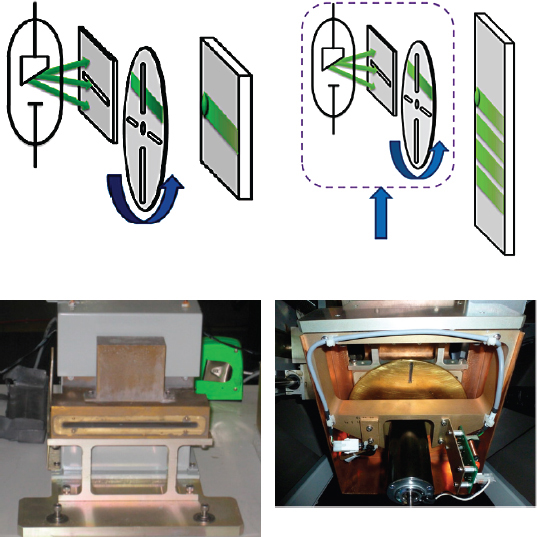
FIGURE 3.1 Drawings of the internal operation of the Rapiscan 1000 single-pose and dual-pose configurations showing the slit and chopper wheel radial apertures generation of a raster scanning pencil beam of X rays (top left). Vertical motion of this whole configuration (top right) allows the pencil beam to cover a large area and thus generate a two-dimensional X-ray backscattered image. The slit aperture (bottom left) and chopper wheel with radial apertures (bottom right) are shown. SOURCE: Courtesy of Erik Svedberg (top) and Mauro Sardela (bottom).
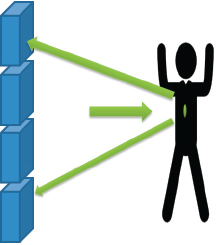
FIGURE 3.2 A backscatter AIT system in use. A small pencil beam illuminates a spot on some part of the scan area (i.e., the body) at any given time, and the large detector rows pick up the backscattered X rays continuously as the spot sweeps. SOURCE: Courtesy of Erik Svedberg.
AIT system. When the wheel rotates, the radial slits traverse across the length of the fan-beam and results in the pencil beam that scans in the horizontal direction; this combination of the horizontal slit and the rotating aperture produces what is commonly referred to as a raster scan. The large area detectors located beside the source integrate the X rays that are backscattered from the person. The resulting signal strength is recorded as a function of the position of the pencil beam. This results in a single horizontal line image of the X rays backscattered from the person.3 The entire housing of the X-ray source, fan-beam collimator, and chopper wheel assembly is vertically translated during the scan so that successive horizontal image lines are displaced to form a two-dimensional image. Because the total vertical travel of the X-ray head is less than the desired scan height, the tube and collimator assembly also rotate about the horizontal axis. As the X-ray assembly approaches the lower limit of travel, it tilts down in order to image the feet of the subject, and as it reaches the top of its travel, it tilts up to cover the tallest individual. The AIT system can scan in both the upward and the downward direction. The result is a two-dimensional X-ray backscattered image of the person being screened. The large area detector consists of two vertical arrays of fluorescent screens that are viewed by large photomultiplier tubes (see Figure 3.2; only one vertical array is shown). An image is generated based on the intensity of backscattered X rays as a function
_______________
3 For an additional description of the rastered spot used, see L.T. Hudson, J.L. Glover, and R. Minniti, The metrology of a rastered spot of X rays used in security screening, Journal of Research of the National Institute of Standards and Technology 119:540-553, 2014, http://dx.doi.org/10.6028/jres.119.021.
of the position of the pencil beam on the subject. Contrast in detected backscatter radiation provides depictive representations of the subject’s body and exposes any concealed objects (e.g., a wallet or an explosive), generating an X-ray backscatter image for each AIT system unit.
AS&E manufactures two X-ray backscatter AIT systems: SmartCheck and SmartCheck-HT. The SmartCheck is a dual-pose AIT system, while the SmartCheck-HT is a single-pose AIT system, where HT stands for high throughput. As stated earlier, the X-ray backscatter manufacturers use the same physics and differ mainly in their implementation.
The fundamental X-ray generation for SmartCheck is similar to the Rapiscan design in that AS&E’s new AIT system employs a tungsten anode X-ray tube that operates at a voltage of 50 kV. They differ in that the AS&E’s X-ray tube current is 12 mA, while Rapiscan’s is 5 mA, and AS&E’s AIT system generates its raster-scanning pencil beam of X-rays by collimating the X-ray cone-beam emitted by the source using a vertical hollow cylinder surrounding the X-ray tube and rotating about its central axis. Several round apertures or holes (see Figure 3.3) emit the desired X-ray beam.
The large area detector on the source side integrates the X rays that are backscattered from the person, and the signal is coordinated with the beam location.
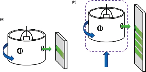
FIGURE 3.3 Apertures or holes in a rotating cylinder emit the sweeping X-ray beam in the AS&E SmartCheck AIT. As each hole traverses the cone-beam of X-rays from the source inside the cylinder, a scanning beam of X rays is generated. In diagram (a), only a line is swept out; in diagram (b), the unit is raised so that an area is swept out. SOURCE: Courtesy of Erik Svedberg.
This generates a single horizontal line (one-dimensional) image of the X rays that are backscattered from the person located in the scanning environment. Differences in backscatter intensity provide contrast in the line image. The entire housing of the X-ray source, fan-beam collimator, and canister assembly is vertically translated during the scan to move the horizontally raster-scanned pencil beam of X rays along the vertical direction. This results in a two-dimensional X-ray backscattered image of the person being screened. A second detector array, on the opposite side of the subject, produces an outline image of the subject. The AIT system can scan in both the upward and the downward direction.
Each scan takes about 3 seconds, or about 6 seconds for both anterior and posterior X-ray backscattered images. A dual-pose model requires time for the person being screened to turn for the second scan. As with the Rapiscan, persons being screened using a dual-pose AIT system are not being subjected to twice the X-ray dose compared to the single-pose AIT system; they are receiving approximately half the X-ray dose for each of the single poses for a total dose equivalent to that from the single-pose AIT system. The actual anterior and posterior doses are given in Chapter 7.
The design of Tek84’s Ait84 is closely related to the Rapiscan Secure 1000; thus, Figure 3.1 best describes how the AIT system works. It is a single-pose AIT system and generates the raster-scanned X-ray spot using a similar horizontal collimating slit with rotating chopper wheel and vertical translation of the housing containing the X-ray tube, collimating slit, and rotating chopper wheel. Similar to the Secure 1000 single-pose AIT system, it completes the series of two scans in 6 seconds. The distinguishing feature of the Ait84 is that during each anterior or posterior X-ray scan, the Ait84 collects the X-ray intensity data from both the fluorescent screens on the active X-ray source side and the fluorescent screen opposite the X-ray source, generating two images, simultaneously X-ray backscattered and X-ray transmission, respectively.4
The fundamental X-ray generation for the Tek84 Ait84 is similar to the Rapiscan Secure 1000 and AS&E’s SmartCheck design (see Figure 3.4). The Ait84 employs a tungsten anode 50 kV and 5 mA X-ray tube voltage and current, respectively. The Ait84 generates an X-ray beam ~6 mm × 6 mm at 75 cm. This AIT system is not equipped with automatic target recognition and, therefore, is not a candidate for deployment at U.S. airports. However, it is used for screening at airports outside the United States, such as airports in Israel.
_______________
4 Presentation by Steven Smith, owner of Tek84, to the committee on April 29, 2014.
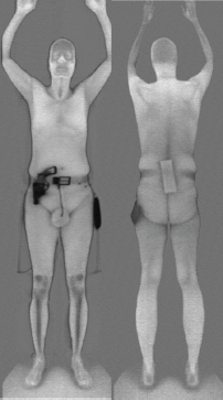
FIGURE 3.4 Composite images, including both transmission and backscatter image data are shown. SOURCE: Scanned images from the AIT84 security scanner, provided by Tek84 Engineering Group, LLC.


