
CHARACTERISTICS OF ESTUARINE DREDGING EQUIPMENT
Thomas W.Richardson
Chief, Engineering Development Division
Coastal Engineering Research Center
U.S. Army Engineer Waterways Experiment Station
Although there is no one type of dredging apparatus designed solely for work in an estuary, the majority of estuarine dredging in the United States is performed by one of three kinds of conventional dredges. In addition, there are many types of nonstandard dredging equipment or techniques that can be used in an estuarine environment. Both conventional and nonstandard dredges can be successful in an estuary if they are matched to the proper job and applied intelligently. This paper will describe briefly the most common conventional U.S. estuarine dredges and will discuss some nonstandard approaches to estuarine channel maintenance problems.
CONVENTIONAL DREDGING EQUIPMENT
Bucket Dredges
The term “bucket dredge” can have different meanings. In Europe, a common type of bucket dredge is the bucket ladder (Figure 1), which excavates the bottom by a chain of buckets that moves around a large pivoting ladder, all in the vertical plane. Material brought to the surface by the buckets is dumped on a chute and falls into hopper barges brought alongside. This type of dredge is virtually unused in the United States except for limited mining applications. Other types of bucket dredges are the dipper dredge, the backhoe, and the dragline, all of which operate like their land-based counterparts (power shovel in the case of the dipper dredge, and all of which usually depend on barges to transport material away from the excavation site.
In the United States, bucket dredge most often means a waterborne version of the terrestrial grab bucket or clamshell crane (Figure 2). Such a dredge can be a specially designed piece of marine equipment. In estuaries, bucket dredges can be used in a variety of situations. They are most often employed for slip, pier, and berthing area maintenance dredging, where the ability to excavate close to structures and to handle debris are important. Bucket dredges are classified by bucket volume, which can range from fractions of a cubic yard to 10, 20, or more. The largest U.S. bucket dredge listed in the 20th annual

FIGURE 1 Bucket ladder dredge and hopper barge.

FIGURE 2 United States bucket grab/clamshell dredge.
Directory of Worldwide Dredge Fleets and Their Suppliers (1986) has a clamshell bucket capacity of 50 yd3. As with other types of bucket dredges, the grab or clamshell must depend on hopper barges to carry material away; the farther the distance between dredging and disposal, the more barges are needed to keep a steady flow of excavation.

FIGURE 3 Modern hopper dredge.
Hopper Dredges
A bucket dredge is a simple device, utilizing the same fundamental mode of operation as the “spoon and bag” dredge or other types of dredges from medieval times. By contrast, the modern hopper dredge (Figure 3) may be one of the most complex collections of systems and subsystems afloat, excluding naval warships. In principle, it is straightforward. The dredge moves along a navigation channel under its own power, pulling a suction tube (dragarm) deployed from each side. The dragarm extends down to the bottom, where it terminates in a suction fitting called a draghead. Onboard pumps drag a sediment slurry through the draghead, up the dragarm, and into hoppers on the dredge. When the hoppers are full, the dragarms are lifted to the surface and the dredge becomes a transport device, taking its hopper load to a disposal site. Usually, the dredged materal is disposed underwater by opening the hopper bottoms and allowing it to fall through the water column. Some hopper dredges have the ability to pump material from their hoppers through a pipeline, making land disposal an option.
What makes a hopper dredge complex is the variety of equipment and crew skills needed to accomplish dredging. In addition to all the usual machinery and systems found on a large ocean-going vessel, a significant amount of the deck and enclosed space on a hopper dredge is taken up by the dredging pumps, motors, reduction drives, piping, valves, davits, and instruments, and by the hoppers themselves. The current industry trend is to instrument and automate as much of the dredging process as possible to increase operational efficiency. As an example, some modern hopper dredges are equipped to automatically shunt low-density suction material overboard (Figure 4), allowing the hoppers to be filled only with more productive higher-density slurry.
An even more spectacular design trend is toward split-hull hopper dredges, wherein the entire vessel separates along its center line to achieve almost instantaneous release of its load.
In an estuary, the hopper dredge is used primarily for major channel maintenance dredging. This is particularly true in entrance channels and the lower reaches of an estuary, where dredged material may be disposed in open water and where wave action, currents, and vessel traffic can be factors in carrying out dredging operations.
Hopper dredges are classified by hopper volume. Small hopper dredges may have hopper volumes of 1,000 yd3 or less. The most prevalent size class of U.S. hopper dredges is the 2,000 to 4,000 yd3 range. The dredge fleet directory lists several U.S. hopper dredges of 6,000 yd3 and greater capacity, including one at 16,000 yd3.

FIGURE 4 Automatic overboard system for low-density slurry.
Pipeline Dredges
The third type of conventional dredge most commonly used in U.S. estuaries is the hydraulic pipeline dredge (Figure 5). Some of the earliest applications of such dredges were in the United States in the mid 1800s. Since that time, it has become the most common type of dredge in the United States. Although there are several types of hydraulic pipeline dredges, including the plain suction, dustpan, and bucket wheel, the term usually connotes the cutter suction dredge. This dredge takes its name from the rotating basket-shaped device used to cut bottom material so it can be drawn into the dredge suction pipe. The cutter, its drive motor and gear, and the suction pipe are all mounted on a structural member called the ladder, which pivots in a vertical plane from the dredge hull (Figure 6). Other major cutter

FIGURE 5 Hydraulic pipeline dredge

FIGURE 6 Cutter suction dredge ladder and cutterhead
suction dredge components are its pumps, power plant, swing winches, spuds, and discharge pipeline. The spuds are two large vertical piles located at the stern that can be independently raised or lowered to the bottom. The swing winches carry wires that pass through sheaves on the ladder and that are connected to anchors set out from the dredge to either side. In operation, with the ladder lowered and the cutter rotating in contact with the bottom, the dredge is swung by one of the
winches to pivot about one of the spuds, sweeping the cutter and suction in an arc across the bottom. At the end of the arc, the process is repeated in the other direction. By swinging about alternate spuds, the dredge can advance to cover new bottom.
Material removed by the dredge can be pumped through the discharge pipeline for a mile or more, depending on a number of variables. In an estuary, the floating portion of the pipeline will usually be supported on pontoons (Figure 7). The floating line will usually lead to a land-based pipeline and eventually into a disposal area. For long pumping distances, booster pumps may be added to the pipeline to provide the required energy.
Pipeline dredges are usually classified by the diameter of their discharge lines, although their cutter and/or pump power is sometimes used as well. The smallest pipeline dredges often fall into the portable category, which means that the dredge is constructed to be transported, either as a unit or in modules, from one job site to another (Corps of Engineers, 1983). Portable pipeline dredge units range from 4–8 in. or larger that can be transported whole, to 24 in. or larger weighing in excess of 400 tons. The larger portable dredges may have more than 2,000 horsepower on the dredge pump and more than 700 on the cutter, but figures of 500 and 100 horsepower respectively are more common for medium-sized portable pipeline dredges (12 to 14 in.). For nonportable pipeline dredges, the trend overseas and to some extent in the United States in recent years has been toward larger and more powerful equipment, with discharge diameters of 32 in. or more. The most powerful cutter suction dredger listed in the dredge fleet directory is a U.S. machine with 30,000 total horsepower.
Due in part to their range of sizes and features, pipeline dredges can perform a variety of functions in an estuary. With variations in anchoring equipment and pipelines, the larger dredges can work in most wave and current conditions found in estuaries or entrance channels.

FIGURE 7 Pontoon discharge pipeline.
However, due to their pipelines, anchor wires, work boats, and other ancillary equipment, they usually pose more of an obstruction to navigation than a hopper dredge. Since they are not self-propelled, they have little ability for collision avoidance.
U.S. Fleet and Costs
According to the dredge fleet directory, the United States dredging industry owns approximately 310 cutter suction pipeline dredges of all sizes, 170 bucket grab/clamshell dredges, and 15 trailing suction hopper dredges. In addition, the Corps of Engineers maintains one 20 in. cutter suction dredge and 4 trailing suction hopper dredges (825, 3,140, 6,000, and 8,000 yd3) as part of its minimum fleet. Costs for the three different categories of dredge are difficult to estimate, since so many site-specific factors influence a dredging job. However, in an attempt to indicate relative costs and approximate ranges, bid data from Corps’ dredging contracts nationwide were estimated for fiscal years 1984 and 1985 and summarized in Table 1. The raw data were listed by contract and dredge type. For this paper, only data from those contracts with one type of dredge were used. Since these one-dredge contracts accounted for more than 280 million yd3 of dredging, the results should be approximately representative of nationwide experience.
Table 1 indicates that the relative ranking by cost of the three dredge types was the same for both years, for both average and lowest contract bid, with bucket dredge contracts being the most expensive per cubic yard and pipeline contractors the least. Total pipeline dredge
TABLE 1 Summary Data for Selected Corps Dredging Contracts, Fiscal Years 1984 and 1985
|
Dredge Type |
Year |
Relative Volume* |
Low Bid Price $/cubic Yard |
|
|
Average |
Lowest |
|||
|
Bucket |
1984 |
1.00 |
3.96 |
1.70 |
|
Hopper |
1984 |
6.56 |
2.15 |
1.20 |
|
Pipeline |
1984 |
24.90 |
1.20 |
0.23 |
|
Bucket |
1985 |
1.00 |
3.95 |
1.90 |
|
Hopper |
1985 |
3.35 |
1.77 |
0.41 |
|
Pipeline |
1985 |
15.89 |
1.30 |
0.25 |
|
*Relative volume is the ratio of the total volume by dredge type in a year to the total volume for bucket dredges for that year for the contracts that comprise the Table 1 data. |
||||
contract volumes were from 16 to 25 times higher than those for bucket dredges, and almost 4 to 5 times higher than those of hopper dredges. There is little question that both in fleet size and volume of work, the pipeline dredge exceeds all other major dredge types combined in the United States.
Highest contract costs per cubic yard can be almost any figure, depending on the particular requirements of a job. Work involving the cleanup of polluted material, small volumes, or long hauling distances can drive contract costs to $10, $15, or $20/yd3 or more, irrespective of dredge type.
NONSTANDARD DREDGING EQUIPMENT
Agitation Dredges
Agitation dredging is a type of dredging that has been practiced in rivers and estuaries for centuries. Although there is no exact definition, it usually involves the suspension or resuspension of bottom material by some type of equipment and the subsequent transport of that material by currents. Richardson (1984) describes a variety of agitation dredging methods and projects. Of those presented, the most promising and applicable to estuaries are rake or beam dragging, propwash, and hopper dredge overflow. The first type involves simply dragging a rake or beam behind a towing vessel to loosen bottom material, with some possible additional augmentation by propeller wash from the towing vessel. This method has been used for a number of years to clean industrial slips and berths in Savannah Harbor, Georgia. Local operators pay the Corps of Engineers an hourly fee for beam dragging operations, on the assumption that the material they remove will have to be redredged by the Corps in the main channel.

FIGURE 8 Propwash agitation dredging vessel.
Propwash agitation dredging usually involves a vessel specially modified for such work (Figure 8). By keeping the vessel in a stationary or slow moving mode and deflecting the propwash downward, bottom material can be effectively resuspended in water several times the vessel’s draft. The Corps of Engineers utilizes a propwash vessel, the Sandwick, in the Pacific Northwest to remove sandy shoals in harbor entrances. In fine-grained material such as is often found in estuaries, the effects of propwash can be dramatic in removing localized shoals.
Hopper dredge overflow is a type of agitation dredging wherein material brought to the surface by a hopper dredge is immediately dumped back overboard. Historically, this has been the principal means of maintaining the southwest pass of the Mississippi River, where high shoaling rates can make conventional dredging unfeasible. However, the large-scale use of hopper dredge agitation in the Delaware estuary from 1905 to 1954 created an apparent increase in shoaling by resuspending fine material which was then trapped within the estuary to form “fluff” layers of low-density sediment.
Costs for agitation dredging are difficult to assess, since there is usually no way to measure its total effects. For localized shoaling, agitation dredging can be several times cheaper than conventional dredging; Savannah Harbor users estimate costs of beam dragging at 1/10 to 1/30 that of other dredging means.
Specialized Equipment
One of the problems in estuarine dredging is that the bottom material is often of a low density, meaning that it contains a large percentage of water that is costly to dredge and transport and to remove from upland disposal areas. A number of companies and individuals have attempted to improve on this situation, the most popular approach being ways to increase the density of material brought up from the bottom. An example of this type of approach is a pump operated by compressed air that is designed to dredge sediment at its in situ density (Figure 9). Originally called the PNEUMA pump by its Italian inventor, the device has been marketed in several countries, including the United States, and has undergone a number of modifications by various licensees. The basic pump consists of three large cylindrical pressure vessels, each with a material intake on the bottom and a compressed air port and material discharge outlet on top. The pump operates on the bottom and uses the difference between ambient water pressure and atmospheric pressure to fill a vessel with bottom material. Once full, material is forced out of the vessel by compressed air and through the discharge line. A basic version of the pump was tested by the Corps of Engineers in 1978 under a variety of typical maintenance dredging conditions (Richardson, 1982). In general, the tests indicated that it could achieve in situ discharge densities in fine-grained estuarine material but not in sand. Power efficiency was low.

FIGURE 9 PNEUMA compressed air pump.
REFERENCES
Anon. 1986. 20th Annual Edition, Directory of Worldwide Dredge Fleets and Their Suppliers. World Dredging and Marine Construction 22(3) 6–101.
Richardson, T.W. 1986. Agitation Dredging: Lessons and Guidelines from Past Projects. Technical Report HL-86–6. Vicksburg, Miss.: U.S. Army Engineer Waterways Experiment Station.
Richardson, T.W., J.E.Hite, Jr., R.A.Shafer, and J.D.Ethridge, Jr. 1982. Pumping Performance and Turbidity Generation of Model 600/100 PNEUMA Pump. Technical Report HL-82–8. Vicksburg, Miss.: U.S. Army Engineer Waterways Experiment Station.
U.S. Army Corps of Engineers. 1983. Survey of Portable Hydraulic Dredges. Technical Report HL-83–4. Vicksburg, Miss.: Waterways Experiment Station.
OVERDREDGING TO REDUCE DREDGING FREQUENCY
Michael J.Trawle
U.S. Army Engineer Waterways Experiment Station
One of the Corps of Engineers’ responsibilities is to improve and maintain navigation channels and harbors. A dredging practice widely used by the Corps’ Coastal District offices in maintaining navigation projects is that of overdredging, often referred to as advance maintenance dredging. The Corps currently uses overdredging to maintain 300 estuarine and coastal navigation projects. Overdredging, or advance maintenance, can either be in the form of overdepth or overwidth dredging. Most of the Corps’ overdredging projects consist of overdepth dredging, generally ranging from 1 to 8 ft. Of the overdepth advance maintenance projects 17 percent use 1 ft, 52 percent use 2 ft, 15 percent use 3 ft, 9 percent use 4 ft, 4 percent use 5 ft, 3 percent use 6 ft, and 1 percent use 8 ft of advance maintenance. The Charleston, Galveston, Mobile, New Orleans, Norfolk, and Portland districts use overdepth advance maintenance the most, accounting for 88 percent of the total projects. A detailed listing of the Corps’ advance maintenance projects is presented by Trawle and Boyd (1978).
DESCRIPTION
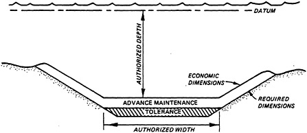
Overdredging or advance maintenance is a practice in which the channel reach is deepened or widened to allow a reduced dredging frequency or to improve project quality. Project quality refers to the percent of time in which a navigation channel remains at project dimensions between dredging activity. Figure 1 shows a typical channel cross section designed with no advance maintenance. The allowable dredging tolerance (usually 1 or 2 ft) is provided for dredging inaccuracies. Figure 2 shows the same channel cross section designed with provisions for advance maintenance as overdepth dredging. Although not as common as overdepth dredging, overwidth dredging is practiced particularly in entrance or approach channels (Figure 3).
Regarding the use of advance maintenance, Engineer Regulation 1130–2–307, paragraphs 9a, b, c, and d, of the Department of the Army, Office of the Chief of Engineers, states:
-
It is the policy with respect to authorized navigation projects to have full project dimensions maintained where


-
feasible and justified. To avoid frequent redredging in order to maintain full project depths, overdredging should be performed in critical, fast shoaling areas to the extent that it results in the least overall cost. Such additional dredging is exclusive of and beyond the allowable overdepth to compensate for dredging inaccuracies.
-
The foregoing pertains not only to projects on which dredging operations are relatively continuous throughout the year, but also to those projects on which dredging is performed periodically and by application of this additional dredging principle dredging intervals could be extended with attendant savings or justified needs of commerce can be satisfied.
-
In the accomplishment of new work dredging, additional overdepth should be performed in those areas in which it is planned to provide additional maintenance dredging depth in accordance with a and b above.
-
Division engineers are hereby authorized to approve additional overdepth for new work and subsequent maintenance in conformance with the above stated policy.
The above regulation says that in high shoal areas where almost continuous dredging is required to maintain the channel, overdredging may be necessary to maintain authorized project depths, and that in areas where periodic dredging is required, advance maintenance may be advantageous since the dredging frequency will be decreased, resulting in lower mobilization-demobilization costs.
A resulting benefit from advance maintenance can be an improvement in the efficiency of the dredging operation itself. For example, a dredge may be capable of a 3, 4, or even 5 ft deep cut in soft material, even though only a 1 or 2 ft cut is required for project depth. In this type of situation, it may be cost effective to include several feet of advance maintenance to allow the dredge to operate with greater efficiency. Also, the advance maintenance allows for greater consolidation or compaction of the material to be dredged, which again can lead to a more efficient dredging operation.
The advantage to project quality of advance maintenance is illustrated in Figure 4. With advance maintenance, the deposited material does not cause loss of project depth until the storage volume provided by advance maintenance has been filled. Ideally, advance maintenance accomplishes two goals: (1) it reduces dredging frequency and (2) improves project quality (Figure 5). In most cases, however, accomplishing only one of these goals by advance maintenance, either improving project quality or reducing dredging frequency, can be considered as an effective application of advance maintenance.

FIGURE 4 Cross sections of navigation channel shoaling with and without advance maintenance.

FIGURE 5 Potential benefits from advance maintenance.
DEPTH VERSUS SHOALING RATE
The key to the effectiveness of advance maintenance is the depth-shoaling rate relationship at the site being considered. Three basic scenarios will be discussed: the channel shoaling rate increases dramatically with depth; the channel shoaling rate is independent of depth; and the channel shoaling rate increases only slightly with depth.
If a project’s shoaling rate increases dramatically as channel depth is increased, advance maintenance will result in significant increases in the amount of sediment required to be dredged, and thus overall maintenance dredging costs will increase. In such cases, advance maintenance should be used as a last resort.
If a project’s shoaling rate is not a function of depth, advance maintenance will be very effective. For example, if a channel shoals at the same rate at a depth of 40 ft as it does at a depth of 30 ft, advance maintenance could be used over the above depth range to reduce the required dredging frequency without any penalty from overall dredging volumes.
If the channel shoaling rate increases only slightly with depth, the cost of advance maintenance must be evaluated considering the increased overall maintenance dredging volumes versus reduced dredging frequency and the improved project quality. The development of an empirical procedure for evaluating the effectiveness of advance maintenance projects in estuaries is discussed by Trawle (1981).
EXAMPLES OF EFFECTIVE ADVANCE MAINTENANCE PROJECTS
Shipyard River Channel, South Carolina
The Shipyard River is a saltwater tidal tributary of Charleston Harbor, South Carolina (Figure 6). From its source, the river flows southerly about 3 mi and empties into Cooper River about 3/4 mi above Drum Island. Current velocities in Shipyard River are low, and the mean tide range is about 5 ft. Material depositing in this river is predominantly clay.
The Shipyard River navigation project, constructed in 1951, requires a 30 ft depth configured as shown in Figure 6. Advance maintenance from 4 to 6 ft has been included in maintenance dredging from 1961 to the present. The following tabulation summarizes the shoaling volumes and dredging intervals with and without advance maintenance:
|
Period |
Project Depth |
Advance Maintenance |
Average Dredging Interval |
Average Annual Maintenance Dredging |
|
1951 to 1961 |
30 ft |
0 ft |
9.1 mo |
539,000 yd3 |
|
1962 to 1977 |
30 ft |
4–6 ft |
12.6 mo |
448,000 yd3 |
As can be seen, even though the dredged depth increased 4 to 6 ft from advance maintenance, the rate of shoaling actually decreased. The required dredging interval increased from about 9 to 13 months, thus

FIGURE 6 Shipyard River Project, South Carolina.
reducing mobilization/demobilization costs significantly and also improving project quality. The detailed evaluation of this project is given by Berger and Boyd (1985).
Coos Bay, Mile 12 to 15
Coos Bay, located on the Oregon coast about 200 mi south of the entrance of the Columbia River and 445 mi north of San Francisco Bay, is rather complex, with 30 tributaries feeding the bay. The largest of these tributaries is the Coos River, which has an average freshwater discharge of 2,200 cfs. Sediment transport to the estuary is estimated to average 72,000 tons annually. The estuary is generally classified by salinity distribution as partly to well-mixed.
The upper portion of the Coos Bay project, Mile 12 to 15, is shown in Figure 7. The project depth of Mile 12 to 15 from 1952 to 1976 was 30 ft. From 1952 to 1962, no advance maintenance was used on the project; from 1962 to 1976, 3 to 5 ft of advance maintenance was used. The following tabulation summarizes the shoaling volumes and dredging intervals with and without advance maintenance.
|
Period |
Project Depth |
Advance Maintenance |
Average Dredging Interval |
Average Annual Maintenance Dredging |
|
1955 to 1961 |
30 ft |
0 ft |
22.2 mo |
470,000 yd3 |
|
1962 to 1974 |
30 ft |
3–5 ft |
45.7 mo |
420,000 yd3 |
As can be seen, even though the dredged depth increased 3 to 5 ft from advance maintenance, the rate of shoaling decreased slightly. Furthermore, the required dredging frequency changed from once every other year to once every four years, a tremendous improvement from the mobilization/demobilization standpoint. The detailed evaluation of the project is given by Berger and Boyd (1985).
Pascagoula Harbor, Entrance Channel
Pascagoula Harbor is located on the Gulf Coast about 61 mi west of Mobile Bay, Alabama and about 44 mi east of Gulfport Harbor, Mississippi (Figure 8). The existing navigation project includes an entrance channel 40 ft deep and 350 ft wide from the Gulf of Mexico through Horn Island Pass, including an overwidth advance maintenance section, 40 ft deep, and 200 ft wide, and about 1,500 ft long at the west end of Petit Bois Island, as shown in Figure 9.

FIGURE 7 Coos Bay project, Oregon.

FIGURE 8 Pascagoula Harbor project, Mississippi.

FIGURE 9 Widened area, Pascagoula Harbor entrance channel.
This overwidth section has existed since 1965. It has proven effective by impounding littoral drift in the overwidth section rather than allowing it to deposit in the navigation channel. Thus the navigation channel remains at or near project depth a much greater percentage of time. The detailed evaluation of this project is given by Trawle and Boyd (in preparation).
PREDICTIVE TECHNIQUES
Rule of Thumb
In the past, rule-of-thumb techniques have been applied to establish the depth versus shoaling rate relationship needed to predict the effectiveness of advance maintenance dredging. For example, the shoaling rate can be described by the simple formula

where I=infill rate, dd=dredged depth, dn=natural or equilibrium depth, and m=empirically derived exponent.
The problem with this approach is that simple empirically derived formulas generally cannot adequately predict shoaling rates as a function of channel depth in a hydrodynamically complex estuarine/ coastal environment.
Historical Data
Another approach is to carefully evaluate a project’s historical dredging records and hydrographic surveys to establish representative depth-vs.-shoaling trends. If sufficient historical data are available, this approach can be very useful to accurately predict the effectiveness of any proposed advance maintenance dredging. One problem that plagues this approach is that for many projects sufficient historical data are not available.
Numerical Models
Recently, numerical sediment transport models have been used at the Waterways Experiment Station to predict advance maintenance effectiveness. Two examples of such models are discussed below.
The first example is the TABS-2 numerical modeling system, used to study sediment transport in Kings Bay, Georgia, by the Hydraulics Laboratory at the Waterways Experiment Station. The primary purpose of the model investigation was to estimate the required maintenance dredging which would result from navigation channel enlargement. In this case, the model was also used to evaluate the effectiveness of different amounts of advance maintenance dredging (Granat, 1986).
The second example is the LAEMSED numerical model, used to study sediment transport at the mouth of the Brazos River, Texas (Weishar et al., in preparation). The primary purpose of the study was to estimate the maintenance dredging requirements for a proposed navigation channel from the Gulf of Mexico to a point several miles upstream of the river mouth. LAEMSED was used to estimate the maintenance dredging requirements for that portion of the proposed channel from the mouth to a point several miles upstream. The simulations included the application of advance maintenance dredging in amounts ranging from 2 to 8 ft.
SUMMARY
Advance maintenance is a procedure that may reduce overall maintenance dredging costs by reducing mobilization/demobilization costs and at the same time improve project quality. The first two
examples of advance maintenance given in this paper represent effective advance maintenance projects: dredging frequency was reduced and project quality improved with no increase in shoaling rates. The third example, did not reduce the dredging frequency but did cause project quality to improve significantly.
In many cases the addition of advance maintenance to a project causes some increase in the amount of material trapped, which means that the increased shoaling rate must be weighed against the reduction in dredging frequency or improved project quality to determine the worth of advance maintenance. Since the potential benefits can be substantial, advance maintenance should be given consideration in any navigation channel requiring periodic maintenance.
Predictive techniques useful for estimating advance maintenance effectiveness include (1) the judicial analysis of dredging records and hydrographic surveys, and (2) the application of appropriate numerical sediment transport models.
REFERENCES
Berger, R.C. and J.A.Boyd. 1985. Effects of Depth on Dredging Frequency, Evaluation of Advance Maintenance Projects. Technical Report H-78–5, Report 3. Vicksburg, Miss.: U.S. Army Engineer Waterways Experiment Station.
Granat, M.A. 1986. Letter Report. U.S. Army Engineer Waterways Station, Vicksburg, Miss.
Trawle, M.J. 1981. Effects of Depth on Dredging Frequency, Methods of Estuarine Shoaling Analysis. Technical Report H-78–5, Report 2. Vicksburg, Miss.: U.S. Army Engineer Waterways Experiment Station.
Trawle, M.J. and J.A.Boyd. 1978. Effects of Depth on Dredging Frequency, Survey of District Offices. Technical Report H-78–5, Report 1. Vicksburg, Miss.: U.S. Army Engineer Waterways Experiment Station.
Trawle, M.J. and J.A.Boyd. In preparation. Advance Maintenance for Entrance Channels, an Evaluation of Projects. Technical Report HL-. Vicksburg, Miss.: U.S. Army Engineer Waterways Station.
Weishar, L.L., M.L.Fields and M.J.Trawle. In preparation. Brazos River Entrance Channel Investigation. Technical Report CERC-. Vicksburg, Miss.: U.S. Army Engineer Waterways Station.
ENVIRONMENTAL CONSIDERATIONS DURING DREDGING OPERATIONS
John D.Lunz
Environmental Laboratory
U.S. Army Engineer Waterways Experiment Station
Environmental considerations during dredging operations focus primarily on water quality changes. Of particular interest are changes in the levels of suspended solids, optical turbidity, dissolved oxygen, and potentially toxic chemical substances such as pesticides and heavy metals. Changes in concentrations of dissolved nutrients are occasionally an issue. The bulk of this work has been reviewed by Stern and Stickle (1978) and Priest (1981).
A second category of considerations is biological. Impact statements associated with operations at the dredging location may describe biological impacts that are indirect or direct. Indirect impacts are the biological responses to dredge-induced water quality conditions, and are the most common among biological concerns. Direct impacts include unusual, low probability events such as collision between a dredge and large aquatic animal such as a manatee or the capture of sea turtles by the suction end of a hydraulic dredge, and higher probability events such as entrainment and mortality of fishes and shellfishes by hydraulic dredges. Although less of a national consideration, when direct impact occurs it may generate intense local concern and publicity.
TWO TYPES OF DREDGES
It is easier to understand how dredging operations may influence a physical, chemical, or biological impact if we know what dredges look like and how they work. Very informative descriptions of dredging equipment and operations are contained in Huston and Huston (1976) and Barnard (1978). The following is directly from Barnard (1978):
Grab/Bucket/Clamshell Dredges
The grab, bucket, or clamshell dredge consists of a bucket or clamshell operated from a crane or derrick mounted on a barge. It is used extensively for removing relatively small volumes of material (i.e., a few tens or hundreds of thousands of cubic meters) particularly around
docks and piers or within other restricted areas. The sediment is removed at nearly in situ density; however, production rates (relative to a cutterhead dredge) are low, especially in consolidated material. The material is usually placed in barges or scows for transportation to the disposal area. Although the dredging depth is practically unlimited, the deeper the depth the lower the production rate. In addition, the clamshell dredge usually leaves an irregular cratered bottom.
Cutterhead Dredges
The cutterhead dredge is the most commonly used dredge in the United States. With this type of dredge a rotating cutter at the end of a ladder excavates the bottom sediment and guides it into the suction. The excavated material is picked up and pumped by a centrifugal pump to a designated disposal area through a 15 cm (6 in.) to 112 cm (44 in.) pipeline as a slurry with a typical solids content of 10 to 20 percent by weight. The nominal size of the dredge is usually defined by the diameter of its discharge pipeline. For conventional cutterhead dredges the diameter of the cutter is approximately three to four times the diameter of the suction pipe. The typical cutterhead dredge is swung in an arc from side to side by alternately pulling on port and starboard swing wires connected to anchors through pulleys mounted on the ladder just behind the cutter. Pivoting on one of two spuds at the stern, the dredge “steps” or “sets” forward (Figure 1). Although the cost of mobilizing a cutterhead dredge is relatively high, its operation is nearly continuous and production rates (i.e., cubic meters of material dredged per hour) are generally high.
WATER QUALITY CONSIDERATIONS
Suspended Solids
The term turbidity, i.e., optical turbidity, is often used in conjunction with discussions of suspended solids. Although levels of suspended solids do affect turbidity, the two terms are not synonymous, but are measures of distinct phenomena. Levels of suspended solids expressed as weight per unit volume, typically as mg/liter, are the subject of the following discussion.
Cutterhead Dredges
Levels of suspended solids on either side and within a 1 m radius of an operating cutterhead were measured in the field by Yagi et al. (1977) who reported a range of 12 to 580 ppm (mg/liter). Values were highest on the side where cutter blades impacted the sediment, presumably due to a carryover of sediment particles in the water flow
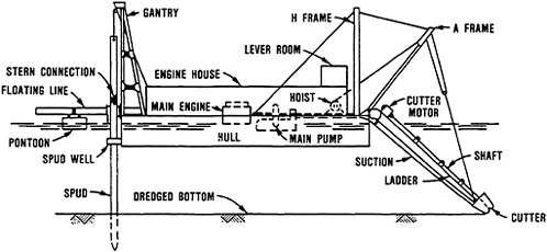
FIGURE 1 The cutterhead dredge. SOURCE: Huston and Huston, 1976.
formed by the rotating blades. Levels of suspended solids 2 m above the cutterhead declined exponentially from between 5 and 74 percent of values near the head.
Studies by Raymond (1984) in the James River, Virginia, and Hayes et al. (in press) in the Savannah River, Georgia, provide data on suspended sediments at varying distances from an operating dredge (Figures 2 and 3). In both studies, levels of suspended sediments greater than 100 mg/liter above ambient were restricted to the lower water column (8 to 10 ft above bottom=2.5 to 3.0 m), while levels in the upper water column remained only slightly above ambient. In the James River study, the ebbing tide had the effect of increasing the vertical dispersion of suspended sediments.
In order to develop a model of dredge-induced turbidity plumes, Kuo et al. (1985) measured suspended sediment concentrations at 1 m below the surface. Values ranged between 9 and 63 mg/liter at distances from 67 to 375 m from the dredge (Figure 4). Background values of suspended solids ranged from 9 to 35 mg/liter. Based on Kuo’s model, sediment concentrations calculated for 1 ft (0.3 m) above the bottom ranged between 2.6 and 353 mg/liter at distances from 22.4 to 2,240 m from the dredge (Figure 4).
Other studies of suspended sediment levels in the vicinity of a dredge report that high levels are generally restricted to within 60 or 79 m and horizontal from the head with very little resuspension above the head (1 to 2 m) (Huston and Huston, 1976; Markey and Putnam, 1976; Sustar et al., 1976; Barnard, 1978; Brahme, 1983; Herbich and Brahme, 1984).


FIGURE 4 Suspended solids concentrations around a dredging operation. Values are measured at 1 m below the surface and calculated at 1 ft above the bottem. SOURCE: data from Kuo et al., 1985.
Bucket Dredges
Suspended solids concentration generated by a typical bucket dredge operation can be traced to four major sources: (1) sediment resuspension at bucket impact and (2) subsequent removal from the bottom, (3) sediment erosion from the open top and mud-covered bucket surfaces as the bucket is hauled upward through the water column, and (4) barge loading and draining (Barnard, 1978). There is great variability in the amount of material suspended by bucket dredges due to bucket size, bucket type (open or closed), volume of sediment dredged per cycle, hoisting speed, sediment type, and hydrodynamic conditions at the dredging site.
Barnard (1978) described a typical bucket dredge operation as producing a downstream turbidity plume extending 300 m (984.2 ft) at the surface and 500 m (1640.4 ft) near the bottom. Average water column concentrations would generally be less than 100 mg/liter. The near-bottom plume will probably have a higher solids concentration (Bohlen et al., 1979; Cronin et al., 1976; Gordon, 1973; Yagi et al., 1977). Within an estuary, bucket dredge-induced resuspension is primarily a near-field phenomenon and represents a relatively small-scale perturbation of the suspended sediment field (Bohlen and Tramontano, 1977). Sediment suspended by a bucket dredge is similar to that produced by a small-scale storm that begins very suddenly, increases the concentrations, and modifies the quality of suspended sediment fields compared with undisturbed conditions. This turbidity plume appears to decay very rapidly following the reduction of energy required to suspend sediments and maintain sediment suspensions.
Settlement of Suspended Solids
Settlement of suspended solids, otherwise called siltation, around a hydraulic dredge was investigated by Earhart (unpublished manuscript) at Black Walnut Harbor in Maryland. Predredging siltation was substantially less (range=1.3 to 5.2 mg/cm during 124 hours) than the siltation that occurred during dredging (range=6.0 to 143 mg/cm during 116 hours) and postdredging (range=13.7 to 285 mg/cm during 114 hours) periods. The high postdredging siltation value was interpreted by Earhart to mean that naturally occurring conditions can cause more siltation than dredging.
Data on suspended solids concentrations reported by Raymond (1984) and Hayes (in press), and sedimentation rates observed by Earhart (unpublished) were used in a computational exercise to estimate the thickness of a hypothetical blanket of sediment that would form if all the suspended material settled to the bottom. James River (Raymond, 1984) and Savannah River (Hayes, in press) data on average suspended sediment concentrations (Figures 2 and 3) were used to estimate the amount of sediment contained in volumes of water located at different depths and different radial distances from a dredge. This data was then used to compute the thickness of a sediment blanket formed as a consequence of a dredging operation. Sediment weight, volume, and blanket thickness computations employed the following assumptions: (1) in situ water content of the settled material was 50 percent by weight, (2) bulk density of the sediment was 2.65 g/cm in the James and Savannah rivers, and 2.68 g/cm at Black Walnut Harbor, and (3) bulk density of water was 1.99 g/cm. The results are presented in Figure 5.
Sediment deposition was calculated in the turbidity plume model of Kuo et al. (1985). Values of sediment deposition density (g/cm) calculated for varying lateral distances from the dredge were 0.29 (at 30.5 m), 0.28 (at 61.0 m), 0.24 (at 152 m) and 0.15 (at 305 m). We estimated thickness of the settled material from this data by assuming an in situ water content of 50 percent by weight and a bulk density of sediment and water equal to 2.65 g/cm and 1.00 g/cm, respectively. Our estimates of sediment thickness were 4 mm at 30.5 m and 61.0 m, 3 mm at 152 m, and 2 mm at 305 m.
Dissolved Oxygen
The effect of suspended sediment on dissolved oxygen (DO) has been studied largely from the standpoint of benthic oxygen demand of the sediments being suspended (Isaac, 1965; Berg, 1970; O’Neal and Sceva, 1971; Reynolds et al., 1973). A few Investigations have reported oxygen concentrations associated with dredged material disposal (U.S. Fish and Wildlife Service, 1970; May, 1973; Slotta et al., 1973; Smith et al., 1976; Westley et al., 1973) and with dredging Itself (Brown and Clark, 1968). Bucket dredging activity in an industrialized New Jersey waterway (Brown and Clark, 1968) was shown to reduce DO levels by 16 to

FIGURE 5 Thickness of the sediment blanket estimated from the settlement of seidments suspended by dredging operations in the James River, Virginia, and the Savannah River, Georgia.
work with benthic oxygen demand has been related to the degree of chemical contamination or organic enrichment. Particular attention has focused on volatile solids (VS) concentrations in sediment because of frequent high correlations between benthic oxygen demand and the percentage of volatile solids. O’Neal and Sceva (1971) reported a significant difference in the initial oxygen demand of sediments having relatively low volatile solids (mean=2.9 percent) and those having reported a relationship between benthic demand (g/h-m) and biological oxygen demand (mg/kg).
Oxygen demand has also been shown to be a function of the amount of suspended sediment (Isaac, 1965; Berg, 1970; Reynolds et al., 1973). Collett (1961, cited in Isaac, 1965) reported a substantial difference in oxygen demand between shaken and quiescent samples from four British rivers. Reynolds et al. (1973) developed a predictive mathematical model for DO demand based on the benthic oxygen demand of the sediment. Benthic oxygen demand was found to be directly related to sediment biological oxygen demand temperature and degree of resuspension.
It is clear from studies of oxygen demand that it is directly related to a number of parameters, including volatile solids concentration of the sediment, temperature, degree of sediment resuspension
(concentration of suspended sediments), and duration of resuspension. Using various levels of suspended sediments reported for hydraulic dredging operations and estimates of low, moderate, and high levels (5, 20, 150 ul 0/g sediment dry weight, respectively) of sediment oxygen demand, we estimated the oxygen demand for a typical dredging operation. The DO reduction was estimated within a hypothetical closed cylinder having a height of 2 m and a radius of 15 m, situated around a cutterhead. The initial DO concentration in the water within the cylinder was 5 mg/liter; the temperature was 25°C.
The estimated dissolved oxygen reduction (Table 1) is generally small (<0.05 mg/liter) for all combinations of suspended sediment and oxygen demand levels. By these computations, a considerable reduction of DO (3.0 mg/liter) would occur only under combined conditions of extremely high suspended solids and high oxygen demand. Dissolved oxygen depressions observed during dredged material disposal operations are higher (>1.0 mg/liter) than those we estimated at the dredging location; however, the levels of suspended sediment are much greater during dredged material disposal. The DO depressions at dredged material disposal sites are reported to be short lived, on the order of hours (U.S. Fish and Wildlife Service, 1970; May, 1973; Westley et. al., 1973; Bernard, 1978).
TABLE 1 Hypothetical Values of Dredge—induced Dissolved Oxygen Reduction, from 5 mg/liter, for Combinations of Suspended Sediment Concentrations and Benthic Oxygen Demand.
are higher (>1.0 mg/liter) than those we estimated at the dredging location; however, the levels of suspended sediment are much greater during dredged material disposal. The DO depressions at dredged material disposal sites are reported to be short lived, on the order of hours (U.S. Fish and Wildlife Service, 1970; May, 1973; Westley et. al., 1973; Bernard, 1978).
Chemical Release from Sediments
The release of naturally occurring chemical substances (nutrients, sulfides, iron, and other metals in naturally occurring concentrations) and industrially derived chemical substances (potentially toxic metals in higher than natural concentrations, organohalogen compounds, and pesticides) by the suspension of sediments during dredging is a concern, particularly in highly contaminated sites. The fate of these compounds when sediments are suspended has received much attention and is thoroughly reviewed by Stern and Stickle (1978).
Metals
Information from laboratory studies suggests that metals from bottom sediments, released when these sediments are suspended, are adsorbed onto clay and organic particles in the water column. Estimates of the percent of various metals adsorbed in this way include 69.8 percent for copper, 97.4 percent for mercury, and 50 percent for mercuric nitrate and mercury chloride. In field situations, the levels of mercury in the water column were reported to be negligible or very slight (Stern and Stickle, 1978).
Windom (1972) suggested a general explanation of adsorption involving iron found in the sediment. Reduced iron, once oxidized during resuspension, actively scavenges metals and other compounds, thereby removing them from the water column. These compounds accumulate in the settling sediments where they are reduced upon return to anoxic conditions. For the most part, therefore, these compounds are generally not available in the water column except as part of an iron complex, and are retained in the sediment by resettlement of these complexes. May (1974) made similar observations during dredged material disposal into containment basins and suggested three possible scenarios to explain them:
-
The processes acting under conditions of dredged material disposal are either too slow or are too quickly reversed to allow sediment constituents to become dissolved.
-
The materials are too strongly adsorbed to either inorganic or organic matter so that reducing conditions have little effect on them.
-
The materials are largely in refractory form (organic and inorganic complexes) and are not readily soluble.
Chlorinated Hydrocarbons
The degree of release of chlorinated hydrocarbons during dredging per se is unknown (Stern and Stickle, 1978; Priest, 1981). The behavior of these compounds in sediment-water systems associated with dredged material disposal alternatives was reviewed by Gambrell et al. (1978) who report that chlorinated hydrocarbons are strongly bound to the solid phase in typical soil and sediment-water systems. They state, “unless a contaminated sediment is coarse-textured with low organic matter content, dissolved compounds will exist at extremely low levels such that this form will not be an acute environmental threat.” Their review further points out that an exception may be where a very high suspended solids-to-water ratio exists and they describe results of laboratory elutriate tests reported by Lee et al. (1975) in which a 20 percent suspended solids system resulted in release to soluble forms while a 5 percent suspended solids system showed less release or no release. Laboratory investigations conducted by Chen et al., (1976) suggest that very fine silts and clays and the quantities of humic and fulvic acids in marine sediments are important factors in controlling the adsorption capacity of chlorinated hydrocarbons in marine sediments. These laboratory observations led to a conclusion that chlorinated hydrocarbons will not be released to solution in detectable quantities under normal conditions. However, these compounds undergo similar association with organic detritus and inorganic sediment particles and are capable of being transferred through the food chain via ingestion by organisms (Chen et al., 1976; Burks and Engler, 1978; Rubinstein et al., 1984). Where substantial suspended solids are present, the oil and grease content of the suspended particulates is reported to be more important in regulating total levels of suspended chlorinated hydrocarbons than actual levels of suspended solids (Burks and Engler, 1978). Lee et al. (1975) suggested the simultaneous occurrence of both oil and grease and chlorinated hydrocarbons may enhance bioavailability.
Nutrients
Quantitative information about the release of nutrients during dredging operations is not available. Qualitative information on the behavior of nitrogen and phosphorus compounds during dredged material disposal in open water can be viewed as applicable as long as the differences in dredging and dredged material disposal operations are recognized in terms of the concentrations and volumes of sediment that they suspend. Stern and Stickle (1978) concluded that turbidity and suspended material can play both beneficial and detrimental roles in aquatic environments. They state that suspended material absorbs and removes contaminants from the water column and stimulates photosynthesis through the introduction of inorganic nutrients. They further conclude that nutrients may stimulate excessive biological growth and that turbidity might reduce photosynthetic activities because of its
interference with light penetration. There is a consensus among reviewers of nutrient release during dredged material disposal operations that ammonia toxicity or an increase in algae productivity should not be problems in most waters where substantial dilution and mixing occur.
BIOLOGICAL CONSIDERATIONS
Restrictions (most commonly seasonal) are applied to federal and permit dredging projects in order to protect sensitive life history stages of important aquatic animals from the physical and chemical alterations of aquatic habitats caused by dredging operations.
Concerns usually are focused on the ecology of specific target species. For example, pelagic egg and larvae of fishes and shellfishes are dependent on local hydrodynamic conditions for transport into and out of project areas and have limited avoidance capabilities. Thus, they are considered to be more susceptible to dredging effects than motile juveniles and adults.
Demersal eggs, or life history stages that are sessile or nonmotile, are viewed as particularly susceptible because of their longer exposure to elevated suspended sediments, or due to smothering by increased sedimentation. Concerns for motile fishes and shellfishes focus upon direct effects of suspended sediments on survival, movement, and migration patterns.
If the experience of the Corps of Engineers can be considered as a valid model, then the following statements apply to this symposium’s discussion:
-
There is little consistency in patterns of restrictions applied within different areas of the United States inhabited by the same kinds of aquatic animals. For example, penaeid shrimp would be classified as important aquatic animals inhibiting areas managed by the Wilmington, Charleston, Jacksonville, Mobile, New Orleans, and Galveston districts of the Corps of Engineers. However, dredging restrictions to protect penaeid shrimp occur only in the Mobile and Wilmington districts.
-
Corps districts tend to comply with dredging restrictions in order to maintain harmonious working relationships with other federal and state resource management agencies. In some instances, however, these restrictions may complicate dredging project scheduling, funding and contracting; increase project costs; increase hazards of field operations; and perhaps, of most importance, may not be supportable with technical data.
Suspended Sediment Effects
The literature relevant to the effects of suspended sediments on aquatic organisms is very dispersed (Cairns, 1968; Sherk and Cronin,
1970; Schubel et al., 1977; Peddicord and McFarland, 1978; Stern and Stickle, 1978; Profiles Research, 1980; Priest, 1981). Table 2, modified from Priest (1981), although far from comprehensive provides a sample of results of laboratory examinations of physical effects of suspended sediments on estuarine and coastal marine species.
Summarization of the results of these studies is hindered by a lack of standardization in experimental protocol (e.g., selection of test concentrations, exposure durations, or suspensions of natural vs. processed sediments) or equipment used to maintain sediment in suspension. The most widely used approach incorporates basic bioassays (LC10 or LC50). Other studies measure threshold concentrations of suspended sediments above which a given species is adversely affected. Several workers have employed histological preparations of gill tissues to demonstrate physical effects. Results have been conflicting. Ritchie (1970) found no evidence of gill pathology in specimens of 11 estuarine fish species prior to and after exposure to dredging conditions. Sherk et al. (1975), however, found disrupted gill tissue and increased mucus production in white perch exposed to sublethal suspended sediment concentrations.
A number of gaps in the knowledge of effects of suspended sediments are readily apparent. Very little is known of the importance, if any, of synergistic effects resulting from combinations of causal factors, or of physical features of the sediment particles such as size or angularity. Rogers (1969) reported that processed sediments (highly angular incinerator residues) were much more toxic to experimental fishes than naturally weathered estuarine sediments. In addition, stresses of a chemical, physical, or biological nature may be manifested in chronic rather than acute effects (Sherk, 1972). Indirect effects of elevated suspended sediments may be of consequence; for example, they may interfere with feeding behavior of visually oriented larval stages, or cause delayed development resulting in asynchronous occurrences of larvae and their prey. Insufficient technical information exists upon which to establish the validity or significance of these issues.
Very few field studies have attempted to test the hypothesis that turbidity fields act as barriers to migratory patterns of sensitive species (e.g., anadromous herrings). Results to date have been largely inconclusive. An extensive sonic monitoring of fish distributions conducted in the Delaware River during dredging operations was unable to detect any dredge-induced changes in fish density or distribution (Martin Marietta, 1975). Variability in fish densities was just as great at sites far removed from the dredge as at the actual dredge site.
Recognizing the inconsistencies and shortcomings that characterize the current literature, we believe that most, if not all, life history stages of species adapted to naturally turbid estuarine conditions are moderately to extremely tolerant of elevated suspended sediment concentrations.
TABLE 2 Summary of Results of Experimental Determinations of Effects of Suspended Sediments on Fishes and Shellfishes.
|
Reference |
Species |
Stage |
Susp. Sed. Conc. (mg/l) |
Exposure Duration |
Type of Sediment |
Degree of Effect |
|
Schubel et al. 1977 |
Yellow Perch |
Eggs |
50–500 |
Not Stated |
Natural |
No significant effect on hatching success; some delay in time to hatching noted in samples at >100 mg/l (for all four species) |
|
" |
White Perch |
" |
" |
" |
" |
|
|
" |
Striped Bass |
" |
" |
" |
" |
|
|
" |
Alewife |
" |
" |
" |
" |
|
|
Morton 1977 |
White Perch |
Eggs |
50–5,000 |
" |
" |
No significant effect on hatching success; definite delay in development at >1,500 mg/l |
|
" |
Striped Bass |
" |
20–2, 300 |
" |
" |
No significant effect on hatching success; definite delay in development at >1,300 mg/l |
|
" |
White Perch |
Larvae |
1,626–5,380 |
24–48 hrs |
" |
15–48 percent mortality |
|
" |
Striped Bass |
" |
1,557–5,210 |
" |
" |
20–57 percent mortality |
|
Auld and Schubel 1978 |
Blueback Herring |
Eggs |
50–5,000 |
Not Stated |
" |
No significant effect on hatching success at all test concentrations |
|
" |
Alewife |
" |
" |
" |
" |
|
|
" |
American Shad |
" |
" |
" |
" |
" |
|
" |
Yellow Perch |
" |
" |
" |
" |
" |
|
" |
White Perch |
" |
" |
" |
" |
Significant effect on hatching success at 1,000 mg/l but not at lower concentrations |
|
" |
Striped Bass |
" |
" |
" |
" |
|
|
" |
Yellow Perch |
Larvae |
50–1,000 |
4 days |
Natural |
Survival significantly reduced at >500 mg/l |
|
" |
Striped Bass |
" |
" |
2–3 days |
" |
Survival significantly reduced at >500 mg/l |
|
" |
Alewife |
" |
" |
4 days |
" |
Survival significantly reduced at >100 mg/l |
|
Stern and Stickle 1978 |
Spot |
Adult |
13,090 |
24 hrs |
Processed |
LC10 |
|
" |
Spot |
" |
68,750 |
" |
Natural |
" |
|
" |
Striped Killfish |
" |
23,770 |
" |
Processed |
" |
|
" |
Striped Killfish |
" |
97,200 |
" |
Natural |
" |
|
" |
Mummichog |
" |
24,470 |
" |
Processed |
" |
|
" |
Atlantic Silverside |
" |
580 |
" |
" |
" |
|
" |
Bay Anchovy |
" |
2,300 |
" |
" |
" |
|
" |
White Perch |
" |
9,970 |
" |
Natural |
" |
|
" |
White Perch |
" |
3,050 |
" |
Processed |
" |
|
Priest 1981 |
Striped Bass |
Subadult |
4,000 |
21 days |
Natural |
" |
|
Saila et al. 1968 |
Cunner |
Adult |
133,000 |
12 hrs |
" |
Median Tolerance Limit |
|
" |
Cunner |
" |
100,000 |
24 hrs |
" |
" |
|
" |
Cunner |
" |
72,000 |
48 hrs |
" |
" |
|
" |
Mummichog |
" |
300,000 |
24 hrs |
" |
No mortality |
|
" |
Sheepshead Minnow |
" |
300,000 |
" |
" |
<30 percent mortality |
|
" |
Cunner |
" |
100,000 |
" |
" |
Median Tolerance Limit |
|
" |
Stickleback |
" |
52,000 |
" |
" |
" |
|
Davis and Hidu 1969 |
American Oyster |
Eggs |
188 |
Not Stated |
Natural |
22 percent abnormal development |
|
" |
American Oyster |
" |
250 |
" |
" |
27 percent abnormal development |
|
" |
American Oyster |
" |
375 |
" |
" |
34 percent abnormal development |
|
" |
American Oyster |
" |
1,000 |
" |
Processed |
No significant effect |
|
" |
American Oyster |
" |
2,000 |
" |
" |
" |
|
" |
American Oyster |
Larvae |
750 |
12 days |
Natural |
31 percent mortality |
|
" |
American Oyster |
" |
2,000 |
" |
Processed |
20 percent mortality |
|
" |
American Oyster |
" |
500 |
Not Stated |
" |
78 percent mortality |
|
Davis 1960 |
Hard Clam |
Eggs |
750 |
" |
Natural |
8 percent abnormal development |
|
" |
Hard Clam |
" |
1,000 |
" |
" |
21 percent abnormal development |
|
" |
Hard Clam |
" |
1,500 |
" |
" |
35 percent abnormal development |
|
" |
Hard Clam |
" |
125 |
" |
Processed |
18 percent abnormal development |
|
" |
Hard Clam |
" |
125 |
" |
" |
25 percent abnormal development |
|
Davis and Hidu 1969 |
Hard Clam |
" |
4,000 |
" |
" |
31 percent abnormal development |
|
Davis 1960 |
Hard Clam |
Larvae |
1,000 |
" |
Natural |
No significant effect |
|
" |
Hard Clam |
" |
500 |
12 days |
Processed |
50 percent mortality |
|
Peddicord and McFarland 1978 |
Spot-tailed Shrimp |
Adult |
50,000 |
200 hrs |
Processed |
LC50 |
|
Priest 1981 |
Black-tailed Shrimp |
Subadult |
21,500 |
21 days |
Natural |
20 percent mortality (contaminated seds.) |
|
" |
Dungeness Crab |
Adult |
3,500 |
" |
" |
LC10 |
|
Schreck 1981 |
American Lobster |
" |
50,000 |
Not Stated |
Processed |
No mortality |
|
Yagi et al. 1977 |
American Oyster |
" |
4,000–32,000 |
Extended |
Not Stated |
Detrimental effect |
|
Martin Marietta 1975 |
American Oyster |
" |
100–700 |
Not Stated |
Mud |
No effect |
|
Mackin 1961 |
American Oyster |
" |
100–4,000 |
" |
Silt |
Reduced pumping |
|
Peddicord and McFarland 1978 |
Blue Mussel |
Subadult |
100,000 |
5 days |
Processed |
10 percent mortality |
|
" |
Blue Mussel |
Adult |
100,000 |
11 days |
" |
10 percent mortality |
|
" |
Blue Mussel |
" |
96,000 |
200 hrs |
" |
LC50 |
Mortality Caused by Dredging Equipment
This paper does not attempt to review instances in which circumstances led to mutilation or death of aquatic animals struck by a dredge or caught in the suction of a hydraulic dredge. The most publicized account concerns the occurrence of sea turtles in the Navy’s Port Canaveral shipping channel during the 1980 maintenance dredging (Rudloe, 1981). It seems adequate to say that the occurrence of large aquatic animals like manatees and sea turtles in the vicinity of a dredging job requires that the equipment selection and operations schedule be directed by the need to prevent avoidable injury to those animals.
Entrainment
For those organisms entrained by hydraulic dredges, the available information suggests that few actually survive. Entrainment studies of juvenile salmon fry (Boyd, 1975; Arseneault, 1981) and juvenile Dungeness crabs (Armstrong et al., 1982; Tegelberg and Arthur, 1976; Stevens, 1981) report dredge-induced mortality rates between 85–98.8 percent and 72–100 percent, respectively. I recently examined available information concerning the entrainment of oyster larvae during hydraulic cutterhead dredging operations (Lunz, 1985), and concluded, not surprisingly, that planktonic larvae of shellfish would be entrained if they entered the flow field induced by a hydraulic dredge. The probability is high that mortality will approach or equal 100 percent of those animals entrained.
The difficult question to answer concerns the effect that dredge-induced entrainment mortality will have on the population dynamics, productivity, and standing stock of commercially harvestable animals in a particular water body. An attempt to answer that question was made during a workshop conducted in August 1985. A working draft of the workshop proceedings (Lunz and LaSalle, 1985) offers preliminary conclusions; the final proceedings will appear as a special edition of the American Malacological Bulletin during 1986. The workshop accomplished the formulation of a simple numerical model of oyster larvae entrainment based on conservative assumptions about dimensions of bodies of water, dredging operations, and larvae distribution (Pritchard et al., unpublished).
A Procedure for Making Decisions About Restrictions to Prevent Biological Impacts
Our examination of the literature describing the direct and indirect effects of dredging on fishes and shellfishes concluded that each dredging job involves a set of project-specific conditions, and that these conditions determine the probability of an adverse impact scenario. We have devised seven questions that can be asked during the
planning of a dredging job. The answers to these questions lead to a determination that (1) the probability for impact is such that no restriction is technically defendable, or (2) the probability for an impact is such that a low-risk decision cannot be made without more information or technically justified restrictions seem appropriate.
1. Is the Dredged Material Chemical Contaminated?
Observations made primarily during controlled laboratory studies, and explanations offered by theories about an organism’s physiological tolerance under natural and pollution-induced stresses (Schreck, 1981), lend support to the contention that animals exhibit greater sensitivity to contaminated suspended sediments than to uncontaminated ones. Testing of material to be dredged should not be required if there is reason to believe it does not contain unacceptable levels of contaminants, or if evidence indicates that resident or transient biological resources inhabiting the system are adapted to elevated levels of suspended sediment-associated chemical contaminants.
2. Is the Material to be Dredged Composed of Processed or Unweathered Angular Particles?
Particles such as incinerator residues and volcanic ash in suspension, apparently cause an adverse response by fishes at concentrations lower than those caused by natural weathered sediments (Rogers, 1969). Most dredging projects will involve natural weathered sediments. A simple microscopic examination of sediment particles from the dredging site, supplemented by available information about the origin of the sediments, is adequate to perform an evaluation.
3. What is the Continuous Open-Water Distance Between the Proposal Dredging Location and a Mainland Shoreline at Mean Low Water?
Many fishery biologists believe that turbidity fields constitute a barrier to the movements of sensitive and highly mobile fishes and shellfishes. Continuous open water may be defined by a line woven among a complex of islands situated between a proposed project and a mainland or by a straight line through uninterrupted aquatic habitat. Evidence indicates that dredging operations produce a suspended sediment field that is contained within very limited spatial boundaries. This is a critical point relevant to this and to three of the four remaining questions. For large bucket-dredging projects, an estimated distance of 500 m (1,640 ft) or more would ensure the persistence of a safety corridor through which fishes can bypass the suspended sediment field if necessary. Of the three principal dredge types—bucket, cutterhead pipeline, and dragarm-hopper—bucket dredges produce the
largest suspended sediment fields (Barnard, 1978; Raymond, in press). Therefore, standards developed for bucket dredges might be viewed as conservative when applied to other dredges. We are unaware of any efforts to compile information about suspended sediment fields produced by small permit dredging operations or shore-based construction operations. These operations probably produce very small suspended sediment fields, but in the absence of field observation data, defensible standards cannot be suggested.
4. Do Local Hydrodynamic Conditions at the Project Location Favor Rapid Sedimentation of Material Suspended by the Dredge?
Certain important benthic biological resources are sensitive to increased rates of sedimentation. A significant acute impact potential exists when conditions favoring sedimentation occur in areas inhabited by these resources. In most instances, a qualitative judgement about conditions favoring sedimentation or dispersion would be required to answer this question. Factors include water current and flow conditions, salinity, bathymetry, and ambient sediment texture patterns.
5. Do Important Benthic or Planktonic Biological Resources Exist in the Vicinity of the Proposed Project?
A very conservative position would consider important benthic biological resources occurring within 500 m (1,640 ft) of a dredging project under conditions favoring rapid sedimentation. Reasonable standards to protect important planktonic resources such as fish or shellfish eggs and larvae are very difficult to define if these resources occur in the vicinity of a dredging project or if they may be transported into a project location during dredging activity. A conservative position would be to assume that dredging should be prohibited in bodies of water inhabited by important planktonic life stages such as striped bass eggs and larvae, or hard clam or oyster eggs and larvae. The literature about the responses of these life stages is neither consistent nor easily interpreted. There are strong scientific arguments for reduced restrictions based on the natural association of “sensitive” shellfish larvae with the sediment boundary layer while they search for suitable setting conditions. When these arguments are coupled with knowledge of suspended sediment concentrations representative of turbidity fields actually induced by dredging operations, prohibition of dredging to protect these life stages appears to be unsubstantiated. An option would be to apply a simple numerical entrainment model such as the one developed in response to the oyster larvae entrainment issue by Pritchard et al. (unpublished).
6. Is There a Natural or Dredged Channel in the Vicinity of the Proposed Project?
A widely accepted professional opinion among fishery biologists is that some important fishes and shellfishes (e.g., anadromous fishes) migrate to upstream spawning grounds or coastal waters via dredged or natural channel corridors. A dredging project within or adjacent to a channel is then assumed to potentially interfere with the upstream or downstream migration. We suggest that unless project-specific information is available, the expression “in the vicinity of the proposed project” should be defined as a distance equal to or less than 500 m (1,640 ft). A channel is either present or absent. Technical information that describes the relationship between a channel’s characteristics (e.g., configuration, cross-sectional profile, depth, etc.) and its use as a fish or shellfish migration corridor is lacking.
7. What are the Natural Seasonal Suspended Sediment Maxima of the Project Area?
Cairns (1968) stated, “Since aquatic organisms survive (or at least enough survive to perpetuate the species) temporary exposure to rather high concentrations of suspended solids, it seems best to relate suspended solids standards to the variations and conditions to which the aquatic species have become adjusted. This would-of course mean that the standards would be based on stream conditions rather than fixed arbitrary standards.” We suggest that the standards against which the answer to this question are compared should be based on ambient (background), seasonal suspended sediment concentration maxima (SSSCM) for the project area. The SSSCM value may have to be estimated rather than directly measured. The inclusion of this question in the list is based on our opinion that it is fundamental to any attempt to construct a method for arriving at socially responsible resource management decisions about restrictions on dredging projects.
If the dredge-induced, suspended sediment concentration field substantially exceeds the SSSCM at the proposed dredging location, and sensitive life stages of significant biological resources inhabit the area within the buffer zone, then imposition of a seasonal restriction would appear to be justified.
Response Criteria
A measure of subjectivity is unavoidable. Rigid criteria against which to compare the responses to the questions are in most instances either inappropriate or technically unsupportable at the present time. The respective importance of site-specific social and political conditions on one hand, and the inadequacy of readily available, quantitative impact data on the other, support this position. The intent behind the formulation of these questions was to focus the
concerns on those resource issues and operational characteristics which the best available data supports as being important or significant. Some degree of subjectivity will always be part of the decision making process. We can only hope to increase the measure of objectivity in the process.
ACKNOWLEDGMENTS
I am indebted to Dr. D.G.Clarke, Dr. T.F.Fredette and Dr. M.W. LaSalle who collaborated with me in preparing the papers that were the primary information sources for this manuscript. Support for the preparation of this manuscript and for my participation in this symposium was provided by the Dredging Operations Technical Support (DOTS) Program at the U.S. Army Engineer Waterways Experiment Station (WES). The DOTS Program Manager is Dr. R.M.Engler. This manuscript was prepared under the direct supervision of Mr. E.J.Pullen, Chief, Coastal Ecology Group; Dr. C.J.Kirby, Chief, Environmental Resources Division; and J.Harrison, Chief, Environmental Laboratory. The Director of the WES is Col. Allen Grum; Technical Director is Dr. R. Whalin. Permission was granted by the Chief of Engineers to publish this information.
REFERENCES
Armstrong, D.A., B.G.Stevens, and J.C.Hoeman. 1982. Distribution and abundance of dungeness crab and Crangon shrimp, and dredging related mortality of invertebrates and fish in Grays Harbor, Washington. Report No. DACW67–80-C-0086. Seattle, Wash.: Washington Department of Fisheries and U.S. Army Corps of Engineers. 349 pp.
Arseneault, J.S. 1981. Dredge monitoring program—1980. Memorandum No. 5902–121–50–2. Field Services Branch, Environment Canada, Vancouver. 8 pp.
Auld, A.H. and J.R.Schubel. 1978. Effects of suspended sediment on fish eggs and larvae: A laboratory assessment. Estuar. and Coastal Mar. Sci. 6:153–164.
Barnard, W.D. 1978. Prediction and control of dredged material dispersion around dredging and open-water pipeline disposal operations. Technical Report DS-78–13. Vicksburg, Miss.: U.S. Army Engineer Waterways Experiment Station. 112 pp.
Berg, R.H. 1970. The oxygen uptake demand of resuspended bottom sediments. Water Pollution Control Research Series No. 16070-DCD-09/70. Washington, D.C.: U.S. Environmental Protection Agency. 34 pp.
Bohlen, W.F., D.F.Cundy, and J.M.Tramontano. 1979. Suspended material distributions in the wake of estuarine channel dredging operations. Estuar. and Coastal Mar. Sci. 9:699–711.
Bohlen, W.F. and J.M.Tramontano. 1977. An investigation of the impact of dredging operations on suspended material transport in the lower Thames River estuary. Highlands, N.J.: NOAA, Middle Atlantic Fisheries Center. 54 pp.
Boyd, F.C. 1975. Fraser River dredging guide. Technical Report Series No. PAC/T-75–2. Vancouver, B.C.: Southern Operations Branch, Fisheries and Marine Service, Environment Canada. 19 pp.
Brahme, S.B. 1983. Environmental aspects of suction cutterheads. Ph.D. Dissertation. Texas A&M University. 166 pp.
Brown, C.L. and R.Clark. 1968. Observations on dredging and dissolved oxygen in a tidal waterway. Water Resour. Res. 4:1381–1384.
Burdick, J.C. III. 1976. Analysis of oxygen demand of sediments. Pp. 319–352 in Proceedings of the Specialty Conference on Dredging and Its Environmental Effects, P.A.Krenkel, J.Harrison, and J.C.Burdick III, eds. New York: ASCE.
Burks, S.A. and R.M.Engler. 1978. Water quality impacts of aquatic dredged material disposal (laboratory investigations). Synthesis report. Technical Report DS-78–4. Vicksburg, Miss.: U.S. Army Engineer Waterways Experiment Station. 35 pp.
Cairns, J. 1968. Suspended solids standards for the protection of aquatic organisms. Purdue Univ. Engineer. Bull. 129(11):16–27.
Chen, K.Y., S.K.Gupta, A.Z.Sycip, J.C.S.Lu, M.Knezevic, and WonWook Choi. 1976. Research study on the effect of dispersion, settling, and resedimentation on migration of chemical constituents during open-water disposal of dredged materials. Contract Report D-76–1. Vicksburg, Miss.: U.S. Army Engineer Waterways Experiment Station. 221 pp.
Collett, W.F. 1961. A preliminary investigation of the pollution of the upper Forth estuary. J. and Proc. Inst. Sewage Purification, Part 5, pp. 418–433.
Cronin, W.B., M.G.Gross, W.R.Taylor, R.C.Whaley, W.C.Boicourt, and J.R.Schubel. 1976. Investigations of dredging operations—Brewerton Cut-off Angle-Patapsco River mouth disposal site. Chesapeake Bay Inst., Baltimore, Maryland. Cited in W.D.Barnard (1978) (3).
Davis, H.C. 1960. Effects of turbidity-producing materials in sea water on eggs and larvae of the clam (Venus (Mercenaria) mercenaria). Biol. Bull. 118(1):48–54.
Davis, H.C. and H.Hidu. 1969. Effects of turbidity-producing substances in sea water on eggs and larvae of three genera of bivalve mollusks. Veliger 11(4):316–323.
Gambrell, R.P., R.A.Khalid, and W.H.Patrick, Jr. 1978. Disposal alternatives for contaminated dredged material as a management tool to minimize adverse environmental effects. Technical Report DS-78–8. Vicksburg, Miss.: U.S. Army Engineer Waterways Station. 148 pp.
Gordon, R.B. 1973. Turbidity and siltation caused by dredging in coastal waters. Unpublished manuscript. Prepared for United Illuminating Co. by Yale Univ., New Haven, Conn. 8 pp.
Hayes, D.F. In press. Guide to selecting a dredge for minimum resuspension of sediment. Environmental Effects of Dredging Technical Notes, EEDP-09–1. Vicksburg, Miss.: U.S. Army Engineer Waterways Experiment Station. 9 pp.
Herbich, J.B. and S.B.Brahme. 1984. Turbidity generated by a model cutterhead dredge. Dredging and Dredged Material Disposal, Proc. Conf. Dredging ’84, Clearwater Beach, Florida, November 14–16, 1984.
Huston, J.W. and W.C.Huston. 1976. Techniques for reducing turbidity associated with present dredging procedures and operations. Contract Report D-76–4. Vicksburg, Miss.: U.S. Army Engineer Waterways Experiment Station. 78 pp.
Isaac, P.C.G. 1965. The contribution of bottom muds to the depletion of oxygen in rivers and suggested standards for suspended solids. Pp. 346–354 in Biological Problems in Water Pollution, C.M.Tarzwell, ed. U.S. Public Service Publication No. 999-WP-25. 315 pp.
Kuo, A.Y., C.S.Welch, and R.J.Lukens. 1985. Dredge induced turbidity plume model. J. Waterway, Port, Coastal and Ocean Eng. 111:476–494.
Lee, G.F., M.D.Piwoni, J.M.Lopez, G.M.Mariani, J.S.Richardson, D.H.Homer, and F.Saleh. 1975. Research study for the development of dredged material disposal criteria. Contract Report D-75–4. Vicksburg, Miss.: U.S. Army Engineer Waterways Experiment Station. 337 pp.
Lunz, J.D. 1985. An analysis of available information concerning the entrainment of oyster larvae during hydraulic cutterhead dredging operations with commentary on the reasonableness of seasonally restrictive dredging windows. Letter report to the U.S. Army Engineer District, Baltimore, prepared through the Dredging Operations Technical Support Program, U.S. Army Engineer Waterways Experiment Station, Vicksburg, Mississippi. 10 pp.
Lunz, J.D. and M.W.LaSalle, eds. 1985. Entrainment of larval oysters during hydraulic cutterhead dredging operations. Working draft proceedings of a workshop held on 19–21 August 1985 at the University of Delaware, Lewis, Delaware. U.S. Army Engineer Waterways Experiment Station, Vicksburg, Mississippi. 160 pp.
Mackin, J.G. 1961. Canal dredging and silting in Louisiana bays. Publ. Inst. Mar. Sci. Univ. Texas 7:262–314.
Markey, J.W. and H.D.Putnam. 1976. A study of the effects of maintenance dredging on selected ecological parameters in the Gulfport ship channel, Gulfport, Mississippi. Pp. 821–832 in Proceedings of the Specialty Conference on Dredging and Its Environmental Effects, P.A.Krenkel, J.Harrison, and J.C.Burdick III, eds. New York: ASCE. 1037 pp.
Martin Marietta Laboratories. 1975. Sonic monitoring of fish in the Delaware River. Unnumbered progress reports. U.S. Army Engineer District, Philadelphia. Unpublished.
May, E.B. 1973. Environmental effects of hydraulic dredging in estuaries. Alabama Mar. Resour. Bull. 9:1–85.
May, E.B. 1974. Effects on water quality when dredging a polluted harbor using confined spoil disposal. Alabama Mar. Resour. Bull. 10:1–8.
Morton, J.W. 1977. Ecological effects of dredging and dredge spoil disposal: A literature review. Technical Paper, U.S. Fish and Wildlife Service. 94 pp.
O’Neal, G. and J.Sceva. 1971. The effects of dredging on water quality in the Northwest. Report No. PB 228 533. Environmental Protection Agency, Region X, Seattle, Wash. 158 pp.
Peddicord, R.K. and V.A.McFarland. 1978. Effects of suspended dredged material on aquatic animals. Technical Report D-78–29. Vicksburg, Miss.: U.S. Army Engineer Waterways Experiment Station. 102 pp.
Priest, W.I. 1981. The effects of dredging impacts on water quality and estuarine organisms: A literature review. Virginia Institute of Marine Science. Special Report in Applied Marine Science and Ocean Engineering 247:240–266.
Pritchard, D.W., M.R.Carriker, R.Mann and M.W.LaSalle. Unpublished. Entrainment of oyster larvae by hydraulic cutterhead dredging operations: Workshop conclusions and recommendations. Submitted to the editor, American Malacological Bulletin for publication during March 1986.
Profiles Research and Consulting Groups, Inc. 1980. Seasonal restrictions on dredging projects by NMFS in the Northeast. Volumes I and II. Environ. Assessment Branch, National Marine Fisheries Service, NOAA.
Raymond, G.L. 1984. Techniques to reduce the sediment resuspension caused by dredging. Miscellaneous Paper HL-84–3. Vicksburg, Miss.: U.S. Army Engineer Waterways Experiment Station. 33 pp.
Raymond, G.L. In press. Techniques to reduce the sediment resuspension caused by dredging. Proc. 16th Texas A&M Univ. Intern. Conf. Dredging. 30 pp.
Reynolds, T.D., R.W.Hann, Jr., and W.F.Priebe. 1973. Benthic oxygen demands of Houston Ship Channel sediments. Texas A&M University. TAMU-SG-73–204. 58 pp.
Ritchie, D.E. 1970. Fish. Gross physical and biological effects of overboard spoil disposal in upper Chesapeake Bay. Chesapeake Bay Laboratory Nat. Res. Inst. Spec. Rep. 3, Univ. Maryland, Solomons. pp. 50–59.
Rogers, B.A. 1969. Tolerance levels of four species of estuarine fishes to suspend mineral solids. M.S. Thesis, Univ. Rhode Island, Kingston. 60 pp.
Rubinstein, N.I., W.T.Gilliam, and N.R.Gregory. 1984. Dietary accumulation of PCBs from a contaminated sediment source by a demersal fish species (Leiostomus xanthurus). Technical Report D-84–6. Vicksburg, Miss.: U.S. Army Engineer Waterways Experiment Station. 25 pp.
Rudloe, J. 1981. From the jaws of death. Sports Illustrated, March 23, 1981. 9 pp.
Saila, S.B., T.T.Polgar, and B.A.Rogers. 1968. Results of studies related to dredged sediment dumping in Rhode Island Sound. Proc. Ann. Northeastern Reg. Anti-pollution Conf. 22–24 July 1968, pp. 71–80. Cited in Saila, S.B., S.D.Pratt, and T.T.Polgar.
1972. Dredge spoil disposal in Rhode Island Sound. Univ. Rhode Island, Mar. Tech. Rep. 2. 48 pp.
Schreck, C.B. 1981. Stress and compensation in teleostean fishes: Response to social and physical factors. In Stress and Fish, A.D.Pickering, ed. New York: Academic Press.
Schubel, J.R., A.D.Williams, and W.M.Wise. 1977. Suspended sediment in the Chesapeake and Delaware Canal. Mar. Sci. Cntr., State Univ. New York, Stony Brook, Spec. Rep. 11, Ref. 77–7. 29 pp.
Sherk, J.A. 1972. Current status of the knowledge of the biological effects of suspended and deposited sediments in Chesapeake Bay. In Chesapeake Science #13 (supplement):S137–S144.
Sherk, J.A. and W.B.Cronin. 1970. The effects of suspended and deposited sediments on estuarine organisms: An annotated bibliography of selected references. Nat. Res. Inst. University of Maryland, Solomons. Ref. 70–19. 62 pp.
Sherk, J.A., J.M.O’Connor, D.A.Neumann. 1975. Effects of suspended and deposited sediments on estuarine environments. In Estuarine Research, Vol. II, L.E.Cronin, ed. New York: Academic Press. 587 pp.
Slotta, L.S., C.K.Sollitt, D.A.Bella, D.R.Hancock, J.E.MaCauly, and R.Parr. 1973. Effects of hopper dredging and in channel spoiling in Coos Bay, Oregon. School of Engineering and Oceanography, Oregon State University, Corvallis. 133 pp.
Smith, J.M., J.B.Phipps, E.D.Schermer, and D.F.Samuelson. 1976. Impact of dredging on water quality in Grays Harbor, Washington. Pp. 512–528 in Proceedings of the Specialty Conference on Dredging and Its Environmental Effects, P.A.Krenkel, J.Harrison, and J.C.Burdick III, eds. New York: ASCE. 1037 pp.
Stern, E.M. and W.B.Stickle. 1978. Effects of turbidity and suspended material in aquatic environments: Literature review. Technical Report D-78–21. Vicksburg, Miss.: U.S. Army Engineer Waterways Experiment Station. 117 pp.
Stevens, B.G. 1981. Dredging-related mortality of dungeness crabs associated with four dredges operating in Grays Harbor, Washington. Washington Department of Fisheries and U.S. Army Corps of Engineers, Seattle, Washington. Report No. DACW67–79–0045. 141 pp.
Sustar, J.F., T.H.Wakeman and R.M.Ecker. 1976. Sediment-water interaction during dredging operations. Pp. 736–767 in Proceedings of the Specialty Conference on Dredging and Its Environmental Effects, P.A.Krenkel, J.Harrison, and J.C.Burdick III, eds. New York: ASCE. 1037 pp.
Tegelberg, H. and R.Arthur. 1976. Distribution of dungeness crabs (Cancer magister) in Grays Harbor, and some effects of channel maintenance dredging and the environment of Grays Harbor, Washington. U.S. Army Corps of Engineers, Seattle, Washington. 94 pp.
U.S. Fish and Wildlife Service. 1970. Effects of fish resources of dredging and spoil disposal in San Francisco and San Pablo Bays, California. Unnumbered Special Report, November 1970. Washington, D.C. 36 pp.
Westley, R.E., E.Finn, M.I.Carr, M.A.Tarr, A.J.Schotz, L. Goodwin, R.W.Sternberg, and E.E.Collias. 1973. Evaluation of effects of channel maintenance dredging and disposal on the marine environment in southern Puget Sound, Washington. Washington Department of Fisheries Management and Research Division, Olympia, Wash. 308 pp.
Windom, H.L. 1972. Environmental aspects of dredging in estuaries. J. Water. Harbor Coast. Eng. Div. ASCE. 98:475–487.
Yagi, T., T.Koiwa, and S.Miyazaki. 1977. Turbidity caused by dredging. Pp. 1079–1109 in Proceedings of WODCON VII: Dredging, Environmental Effects, and Technology.
HYDROGRAPHIC SURVEYING
Ellis D.Hart
Research Hydraulic Engineer
U.S. Army Engineer Waterways Experiment Station
Hydrographic surveying is the branch of surveying that includes determination of the configuration of the channel cross section, depth of the water, and position and dimensions of shoals. Clear channels are required to provide traffic lanes for all types and sizes of waterborne vehicles, i.e., military, commercial, and pleasure. Obstructions to these channels, such as shoals, must be removed by dredging. Therefore, one of the primary functions of a hydrographic survey is to obtain data for preparing sounding charts to be used by dredge personnel to dredge areas that are not at the required project depth. This need is made more critical by the tendency toward larger (deeper draft) and faster ships. To meet this need, a hydrographic surveying program with proper equipment, methods, and trained personnel must be established.
A hydrographic survey is accomplished by running a predetermined system of sounding lines. A survey system must be chosen that will thoroughly and economically delineate the bottom relief. A series of evenly spaced, parallel sounding lines is one method of accomplishing this. Generally, these lines will be normal to the channel center line; however, many hydrographic surveying units survey parallel to the center line and prepare computer-determined cross section lines.
The spacing of sounding lines to properly develop a channel section depends on the depth of the water, character of the bottom relief, and importance of the area being surveyed. The spacing of lines should give a good representation of depths and should be sufficiently close to give an indication of all submerged dangers.
Survey schedules are established from experience. For example, some channel reaches remain shoal free for long periods, which generally dictates infrequent, longitudinal surveys (along the channel center line) with maximum spacing. On the other hand, areas that shoal regularly require frequent, closely spaced survey lines.
Survey lines are generally developed in advance and entered into the survey boat computer. This boat system, which receives continuous position input (discussed elsewhere), in turn updates the helmsman’s “left-right” indicator for keeping the boat on the designated survey line. All surveys should be tied into an established grid system. For horizontal control, surveys should be tied to the state plane
coordinate system or geographic positions; vertical control should be tied to the National Geodetic Vertical Datum (NGVD).
In hydrographic surveying, two basic measurements are made continuously: water depth and boat position. Obviously, both measurements must be made with equal accuracy. An accurate depth measurement plotted at a poorly determined boat position is as useless as an accurately positioned point on a chart with an inaccurate depth measurement.
There are many “mechanical” methods of obtaining depth and boat position (ASCE, 1983; Downing, 1973; Hart and Downing, 1977). The methods are ingenious and have been streamlined over the years. Though these methods and equipment were valuable tools to the surveyor, they have generally been replaced by modern, usually fully automated, electronic survey systems. A discussion of depth measurement and positioning equipment will be made followed by the combination of these components into a complete surveying system.
DEPTH AND POSITIONING UNITS
Depth
Soundings provide the principal means of determining the bottom relief of a body of water. Each sounding depth is referenced to a water surface level at the time and place it is made and then corrected to the datum determined by a gauge. In order that the bed may be plotted on a map, the location with reference to a grid of land stations must be determined.
Nearly all water depths are now obtained by echo sounders, which record a continuous profile of the bottom under the survey vessel. Echo sounders operate on the basic principle that a sound produced near the surface of the water will travel to the bottom and then be reflected to the point of origin as an “echo.” This is accomplished by an electric pulse which is mechanically converted to sound by a transducer in the boat hull.
Sound travels in water at a constant velocity; however, this velocity is dependent upon temperature, salinity, and depth (pressure). The sounder is operated at a pre-set velocity of propagation which is determined by calibration. The depth is then determined by the elapsed time required for the signal to complete the round trip to the bottom and back. The returning, amplified signal creates a mark on the depth chart that corresponds to the depth.
The resolution of a system is dependent upon the signal frequency. The higher the frequency, the better the resolution. Most depth sounders designed for use in relatively shallow water use a frequency of 100 to 200 kHz to achieve good resolution. There are factors (to be discussed) which dictate an upper limit for the system frequency.
Transducer beam width has an important effect on accuracy and what is revealed in the depth record (Downing and Fagerberg, in preparation). Beam widths vary from a few degrees to 30 degrees, with the optimum choice depending on application. Transducer beam width is
inversely proportional to size at a given frequency, and inversely proportional to frequency at a given physical size. The net result is that most narrow-beam, depth sounder transducers are large, high-frequency units (≥100 kHz), and most broad beam transducers are smaller, low-frequency units (<100 kHz).
Best resolution is achieved with a high-frequency, narrow-beam-width transducer. The reflected signal comes from a small area on the bottom. Extraneous reflections from side slopes and other irregularities are thereby kept to a minimum. For instance, if the bottom is sloping and the transducer band width is wide, an erroneous depth will be recorded. This then seems to dictate the use of a high-frequency, very narrow-beam-width signal. However, a very narrow beam width restricts the speed of the survey boat, and except in very shallow water, the boat could exit the area of the signal before it is reflected back to the transducer. Therefore, beam widths of less than 3° are not appropriate.
To achieve accurate depth measurements by sonic sounding, instruments must be calibrated for the range of depths to be encountered during the survey period (Blanton, 1982). Calibration may be accomplished by a bar check, which consists of lowering an acoustic reflector, such as a flat metal plate or I-beam, to a known depth below the transducer and adjusting the recorder to produce an equivalent depth reading.
Most depth surveys are conducted with a single transducer emitting an acoustic signal from the survey boat keel as described previously. As the boat traverses the body of water, a series of depths is recorded. Therefore, one pass of the survey boat provides one “line” measurement of depth, usually either perpendicular or parallel to the channel center line.
The pulse rate (time delay between transmitted pulses) is dictated by the maximum anticipated depth in the area to be surveyed and the velocity of sound in the body of water. The pulse rate is set so that transmitted signals do not interfere with a returning (reflected) signal.
In some case, it may be necessary to obtain very close runs to ensure that no navigation obstacles are missed, resulting in a very time consuming and expensive effort. As an alternate to the single transducer system, multiple transducer channel-sweep systems are available. These systems utilize an array of transducers that transmit overlapping acoustic beams, providing complete coverage of the bottom. The transducers can be mounted on booms projecting from the sides of the survey boat or they can be mounted on a floating boom pushed by the survey boat. The optimum width of boom will depend on operating conditions in a given area. One pass with such a channel-sweep system will equal many passes with a single transducer system, thereby saving many hours of operating time where full coverage is required (Figure 1). Data can be displayed either in analog form or digitally. Use of digital techniques permits the display of many more transducer signals on one recorder. In addition, shoaling or minimum depth can be emphasized by automatic outlining or shading.

FIGURE 1 Multi-transducer surveys. Photograph courtesy of Ross Laboratories.
Efficient large-scale survey operations require much more electronic equipment than a depth sounder alone. In order to handle the tremendous volume of data normally collected without excessive time and labor, it is necessary that the depth sounder be designed as an integral part of a fully automated, electronic package. In this automated system, the depth, in the form of an electrical signal, is continuously fed into the data processing unit along with the boat’s position signals. Automatic control is now available for data gathering and data recording. This automated, central control can be extended to direct control of the boat during survey runs if desired (pilot guidance). Also, in addition to recording the data on magnetic tape, the depth data can be automatically plotted in real time as the survey proceeds. A fully automated boat showing the transmitted depth signal is presented in Figure 2. A schematic of an automated system is presented in Figure 3.
Positioning
Manual methods of positioning are still in use in some areas. However, the increasing volume of hydrographic survey data required for a variety of studies dictates that more efficient techniques of surveying be employed that utilize modern electronic equipment. A wide variety of these new positioning techniques have become operational in recent years.
Basically, present techniques are electronic adaptations of earlier manual methods. One of the most widely used positioning techniques utilizes electronics to measure distances between the survey boat and two or more shore-based responders (Figure 2); it is called the “range-range” method of positioning.
The position of the survey boat is calculated by trigonometric solution for which, in this case, the length of all three sides of a triangle is known (trilateration). These sides consist of the reference line (distance between the two responders), plus the two electronically measured distances. The responders are situated over presurveyed locations, which are tied to an accepted grid in order to establish boat position for plotting purposes.
A “range-azimuth” system is formed if electronic distance measuring equipment (EDME) is utilized for one range only and coupled with a

FIGURE 2 Fully automated survey boat.

FIGURE 3 Hydrographic survey system.
manual or automatic optical tracker (ASCE, 1983). Obviously, optical instruments are limited by transmission path obstructions such as fog, snow, rain, and smog that would not, in all cases, limit the EDME. In a range-azimuth system, the limiting link is generally the optical segment.
The shore station responders and boat transmitter/receiver are replaced by underwater units if an acoustic positioning system is
used. This system transmits an acoustic signal in the water that is either intercepted by the acoustic responders or simply reflected off the bottom. For the passive system (no responder), the shift in frequency of the reflected energy is related to the velocity of the survey boat. Displacement can be mathematically derived from velocity, i.e.,
This system has no significant distance limit, entanglement, current problems, or boat speed limitations; however, cumulative errors present a problem. Also, the frequency shift circuitry of the system assumes a stable bottom. A significant layer of moving sediment presents a frequency shift that will cause a false computation of vehicle position.
In one available system (ASCE, in preparation), the boat operator may select any of up to 8 (from a total of 32) transponders. The referenced system is fully automatic, meaning immediate ±1 m of accuracy over the full range, in all operating temperatures, using any set of transponders available. The multi-user system permits up to 16 users to operate from the same remote units.
The operating frequency, or that portion of the spectrum in which a particular system operates, is one of the most important points to be considered when selecting a positioning system. This is because frequency has a strong influence on operating range and position accuracy. Generally, range is inversely proportional to frequency, due primarily to the lower losses at lower frequencies. On the other hand, accuracy is directly proportional to frequency due to better time resolution with short-wave-length operation and greater certainty about path length. Table 1 lists the frequency designations and corresponding ranges of frequency in which positioning systems operate.
TABLE 1 Designation of Frequency
|
Designation |
Symbol |
Frequency |
|
Very low frequency |
VLF |
10–30 kHz |
|
Low frequency |
LF |
30–300 kHz |
|
Medium frequency |
MF |
300–3000 kHz |
|
High frequency |
HF |
3–30 MHz |
|
Very high frequency |
VHF |
30–300 MHz |
|
Ultrahigh frequency |
UHF |
300–3000 MHz |
|
Microwave frequencies |
S-band X-band |
3–30 GHz |
|
SOURCE: Downing and Fagerburg, 1986. |
||
Positioning systems operating in the VLF, LF, MF, and HF frequencies are operable well beyond the horizon, frequently to ranges of several hundred miles. Those systems operating at VHF and above, in general are limited to line-of-site ranges, not very much beyond the optical horizon. On the other hand, VHF, UHF, and microwave systems are generally, capable of more precise distance or position measurements, than are the lower frequency systems. Other important points to be considered regarding operating frequency include (1) the somewhat larger and more cumbersome antennas which are normally required by the lower frequency systems (MF and HF), and (2) the greater susceptibility of the higher frequency systems (VHF and UHF) to “multipath” problems.
HYDROGRAPHIC SURVEY
System Components
The previous sections dealt with the individual depth and positioning units of a hydrographic survey system. This section deals briefly with these and the other components which make up a complete hydrographic survey system. The purpose is to show how the measured data are incorporated into the system to form the final product: a depth at a point on the survey chart.
Control System
Figure 3 shows the components that make up a typical automated hydrographic survey system. Note that all components are connected to the data processor, which is the control center of this particular system. In sophisticated systems, control would be maintained by a computer; in smaller, less automated systems, control unit would be a data logger. The system control units and their capabilities are summarized below.
Operating under the system program stored in its permanent memory, the control unit (computer or microprocessor) receives range data from the positioning system. It processes this data using coordinate and control information entered at the operator’s data terminal (Figure 3). These data are then correlated with other external data, such as the depth soundings from the digital depth recorder, and used to drive the other peripheral elements and to record the survey information.
The control unit has three basic functions:
-
Gather positioning information and compute the position of the boat in its grid coordinate system.
-
Gather other data, such as time and depth, and correlate this information with the position data. The combined data may then be transferred to a magnetic tape, a printer, or a plotter.
-
Compare the present boat position with a preplanned position or course and deliver guidance output that can be used to reposition the boat.
Positioning System
The positioning system shown in Figure 3 consists of the transmitter-receiver with antenna, a range console, and the reference stations or transponders. The position information is fed to the control system as described above.
Track Indicator
Many surveys are conducted along preselected lines. This is made possible by continuously updated position information provided to the track indicator by the control unit. The indicator gives the boat position as left or right of the given line, which is used for maintaining course. The position information is also used to display the boat position with respect to the distance traveled down the preset survey line.
Track Plotter and Tape Recorder
The track plotter continuously plots the boat position on preselected survey lines drawn onto the chart. It is usually a moving-pen, moving-paper plotter but may be a moving-pen-only type plotter (flat bed plotter). When the control unit is a computer, the depth measured at each position may be printed onto the chart. This constitutes a fully automated, on-line system. As an alternative, the data may be stored on a magnetic tape or cassette for processing and plotting at the land-based computer center as shown in Figure 3.
Digital Printer
The digital printer is an option which may be included as a unit of the system. It provides hard copy data for instantaneous analysis, which is sometimes desirable. Information provided includes time of day (to the second), range readings, depth, and other parameters if desired. This information is provided virtually instantaneously.
Depth Sounder
The depth sounding equipment, an integral part of the system was discussed previously.
System combinations may vary from independent range and depth units (manual plotting) to a fully automated system that includes a computer with on-line plotting of all survey data. Computer controlled systems offer the greatest capability and versatility, but require relatively large boats. Small-channel surveying requiring smaller boats is normally restricted to data-processing or data-logging type systems,
although small boat systems are now being developed that are fully automated, utilizing microprocessors.
Satellite Navigation
Satellite navigation and positioning methods are new and developing. Existing satellite systems provide navigation information useful to navigators and geodetic and hydrographic surveyors. Present applications include absolute position reference, calibration of localized referenced systems, extension of onshore control to offshore applications, relative position grid development, and marine navigation. The future of satellite surveying appears to be unlimited. In 1970, the U.S. Department of Defense (DOD) began a review of all navigation systems according to cost and need. The result called for a reduction in the number of DOD funded navigation systems and the development of a single Defense Navigation Satellite System. The selected system was entitled the NAVSTAR Global Positioning System (GPS). The best features of other satellite programs were combined to form the basis for this system, which would eventually permit continuous worldwide surveying and navigation in three dimensions with an accuracy not previously obtainable in dynamic situations.
The GPS consists of a constellation of satellites, a master-control station, several tracking stations, an upload station, and an unlimited capacity for users. The satellites broadcast information continuously so that any user located in any part of the world is able to compute near-real-time files at any time. A total of 24 satellites, 8 in each of three circular planes and approximately 20,000 km in radius, will comprise the completed space segment. At least 6 satellites will be visible at any given location and time.
REFERENCES
American Society of Civil Engineers. 1986. ASCE Task Committee on Measurement and Analysis of Bed Forms (in preparation). New York: American Society of Civil Engineers.
American Society of Civil Engineers. 1983. Measurement of hydrographic parameters in large sand-bed streams from boats. Task Committee on Hydrographic Investigations. New York: American Society of Civil Engineers.
Blanton, J.O. III. 1982. Procedures for monitoring reservoir sedimentation. Technical Guidelines for Bureau of Reclamation. Denver, Colo.: U.S. Department of Interior.
Comstock, A.L. 1984. Radiopositioning systems, present and future; their comparative characteristics and applicabilities. Presented to Pacific Congress on Marine Technology, Honololu, Hawaii, April 24–27, 1984. Hampton, Va.: Teledyne Hastings-Raydist.
Downing, G.C. and T.L.Fagerburg. In preparation. Evaluation of vertical motion sensors for potential application to heave correction in Corps’ hydrographic surveys. U.S. Army Engineer Waterways Experiment Station. Vicksburg, Miss: unpublished.
Downing, C. 1973. Supplement No. 1 to the Hydrographic Survey Conference, 30–31 May 1973. Vicksburg, Miss.: U.S. Army Engineer Waterways Experiment Station.
Hart, E.D., and G.C.Downing. 1977. Positioning techniques and Equipment for U.S. Army Corps of Engineers Hydrographic Surveys. TR H-77–10. Vicksburg, Miss.: U.S. Army Engineer Waterways Experiment Station, CE.
Ingham, A.E. 1974. Hydrography for the Surveyor and Engineer. New York: John Wiley & Sons.
Klein Associates, Inc., Undersea search and survey. Unpublished literature. Klein Drive, Salem, New Hampshire.
Laurila, S. Electronic surveying and navigation. New York: John Wiley & Sons.
Laurila, S. Electronic surveying and practice. New York: John Wiley & Sons.
National Oceanographic and Atmospheric Administration. 1977. Positioning Systems. Report on the Works of WG 4146, XV International Congress of Surveyors, Stockholm, Sweden, June 1977.
Racal Positioning Systems Limited. Unpublished literature. Kingston Road, Leatherhead Surrey KT22 7ND, England.
Raytheon Company. 1966. Underwater acoustics, a brief description, Submarine Signal Division, P451-Aug 66. Portsmouth, R.I.
Raytheon Company. Ocean Systems Center. Unpublished literature. Portsmouth, Rhode Island.
Von Dyck, S. 1976. Radio aids hydrographic surveying. Course Notes, Hydrography II, Canadian Hydrographic Service.
CASE HISTORY, SAVANNAH HARBOR GEORGIA
Henry B.Simmons
U.S. Army Engineer Waterways Experiment Station (Retired)
In 1962, I conducted a brief study of Savannah Harbor, Georgia to determine how shoaling rates and patterns in the harbor had responded to several changes in length and depth of the navigation channel. The results of this study were first published in the minutes of the Federal Interagency Sedimentation Conference of the Subcommittee on Sedimentation, Inter-Coastal Waterway Research, held in Jackson, Mississippi, on 28 January–1 February 1963. They were subsequently republished as Technical Bulletin No. 8, Committee on Tidal Hydraulics, Corps of Engineers, U.S. Army, March 1965. Although both of these publications are out of print, copies can be obtained on loan from the Research Center Library, Waterways Experiment Station.
Figures 1 through 5 are from the 1962 study. Figure 1 is a location map of Savannah Harbor and shows channel stations throughout the harbor. Figure 2 shows the four channel conditions included in the study. Figure 3 shows the net distribution of flow in the harbor for condtions of the 34 ft channel (1953–1954 conditions on Figure 2). Figure 4 shows the relationship betwen bottom flow predominance and shoaling distribution for the 1953–1954 channel condition, and it may be noted that the regions of heaviest shoaling brackets the location of the point of zero flow predominance in Front River. Figure 5 shows average annual shoaling in the downstream, central, and upstream one-thirds of the harbor for the four channel conditions, as well as the average annual shoaling for the entire harbor for each channel condition.
Several significant changes in shoaling patterns and rates were revealed by the study. First, as the harbor channel was progressively deepened and/or extended upstream, the region of heaviest shoaling moved progressively and/or extended upstream. The region of heaviest shoaling moved progressively from the downstream one-third of the harbor to the central one-third and then to the upstream one-third. This major change in shoaling pattern was attributed to intensification of density current action as the channel was deepened or extended, with the result that the nodal point for bottom flow predominance progressively moved in the upstream direction with each change.
Second, the total shoaling rate of the harbor increased progresively as the channel was deepened and/or extended. However, it was


FIGURE 4 Relation of shoaling and performance of bottom flow.

FIGURE 5 Past and present shoaling characteristics of Savannah Harbor.
noted that the latest increase in channel length and depth (1953–1954), which was by far the most drastic of those accomplished during the period covered by the study, increased total shoaling of the harbor by only about 15 percent, compared to much larger percentage increases for the earlier increases in length and/or depth. This finding suggested that shoaling in Savannah Harbor is probably source-limited to about 7
million yd3 per annum, and if so, further increases in channel length or depth would probably not be accompanied by major increases in total shoaling.
Subsequent to the study just described, the Savannah Harbor navigation channel was deepened to 36 ft, and several years later most of it was further deepened to 40 ft. Dredging accomplished for these greater channel depths verify the conclusions reached during the study; namely, that shoaling of this harbor is source limited at about 7 million yd3 per annum. It is my understanding that, until an improvement plan (to be described later) was implemented, there was some further increase in shoaling in the upstream one-third of the harbor and an accompanying reduction in shoaling in the central one-third. This continuing trend indicates that density current effects were further intensified by these two additional increases in channel depth, with the result that the nodal point for bottom flow predominance moved still farther upstream.
At the conclusion of the reference study, a plan of improvement for Savannah Harbor was suggested that was estimated to substantially reduce the cost of maintenance dredging, although no reduction in the total volume of maintenance dredging was expected. Concentration of most of the shoaling in the upstream one-third of the harbor by channel improvements had resulted in an extremely high-cost dredging activity in Front River for several reasons. First, shoaling was so rapid that dredging had to be done frequently, thus requiring numerous expenditures for mobilization and demobilization of dredging plant. Second, the upstream one-third of the harbors is extremely congested because of the many docking facilities and related movement of vessels, so dredging operations were not very efficient in this environment. Finally, the region of heavy shoaling was far removed from suitable disposal areas, so that retention dikes had to be constructed well above optimum height, or long dispoal lines with booster pumps had to be employed to reach satisfactory disposal areas.
The improvement plan suggested for Savannah Harbor is shown in Figure 6 and consisted of three principal elements: (1) a large sediment basin to be dredged in lower Back River, with a deep channel connecting the sediment basin to the navigation channel; (2) a dam with tide gates located in Back River just upstream from the sediment trap, the gates to open at the start of the flood current phase in Back River and close at the end of the flood current phase; and (3) a channel connecting Back and Front rivers at the mouth of the Middle River.
In operation, the tide gates would remain open during the flood current phase in Back River, allowing the tidal prism of Back River to fill in the normal manner and sediment-laden water to be drawn into the sediment basin from the navigation channel. When the tide gates closed at the end of the flood current phase, the tidal prism of Back River upstream of the dam would flow through the connecting canal and then through Front River, substantially increasing the ebb current velocities in Front River and causing deposited sediments to be resuspended and carried downstream past the junction of Back and Front rivers where they could be drawn into the trap during the next flood current phase. Closure of the tide gates during the ebb current phase would reduce ebb

FIGURE 6 Elements of sediment trap plan.
current velocities in lower Back River to such extent that an environment conducive to rapid deposition of suspended sediments in the trap area would be created.
It was estimated that if this plan were constructed and placed in operation more than one-half of the future dredging in Savannah Harbor would be accomplished from the sediment trap. It is very significant that the trap would be located adjacent to an extensive area that could be developed to accommodate spoil disposal for a great number of years. It was also estimated that the greatest effect of the plan would be felt in Front River, since the significantly increased ebb current velocities should greatly reduce shoaling in this region of high-cost maintenance dredging.
The improvement plan just described was completed and placed in operation in 1977. For the next five years (1977–1982), average annual shoaling of Savannah Harbor was 6.8 million yd3 of which 59 percent was dredged from the sediment trap and the remaining 41 percent was dredged from the navigation channel. While I am unable to make direct cost comparisons for maintenance dredging of Savannah Harbor under pre-and post-improvement plan conditions, it is certain that the improvement plan provides substantial monetary savings for the following reasons:
-
Almost 60 percent of the total maintenance dredging is performed in the sediment trap where only limited movement of the dredge is required and there is no interference with dredging operations by ship movements, thus maximizing dredge efficiency.
-
The sediment trap is located adjacent to an extensive area. suitable for spoil disposal.
-
The reduction in navigation channel shoaling effected by the improvement plan significantly increases the time interval
-
between dredging operations and thus reduces the amount expended for dredge mobilization and demobilization.
-
The plan effected a major reduction of shoaling in Front River, which was the highest unit cost dredging area in the harbor.
-
The capacity of the sediment trap is about 9 million yd3, which is sufficient to accommodate more than two years of normal deposition, so dredging to restore the trap can be scheduled to take advantage of efficient scheduling of equipment and favorable weather conditions.
Annual maintenance dredging requirements for pre- and post-improvement plan conditions in Savannah Harbor indicate that plan operations did not increase total maintenance dredging; in fact, average annual maintenance dredging appears to be a few hundred thousand cubic yards less following implementation of the improvement plan. This reduction, if it is real, is believed to be attributable to improved dredging efficiency under plan conditions. All dredges tend to agitate and resuspend more sediment than they physically remove from the channel, and this tendency should be reduced to a minimum in dredging from the sediment trap. Any reduction in resuspension and loss of sediment to the system during dredging operations effectively reduces the total sediment source and this should reduce annual maintenance dredging requirements.


