
Appendix E
Background Information on FALCON Launch Vehicle Concepts
AIRLAUNCH
AirLaunch’s fundamental design concept for its FALCON vehicle, QuickReach, is a two-stage vehicle. It uses liquid oxygen (LOx)/propane, ablative chambers, and a pressure-fed propulsion system for both stages.1 The technology utilized for tank pressurization for both the LOx and the propane is termed vapor pressurization and is known as VaPak. This basic approach to tank pressurization was studied by Aerojet in the early 1960s. It was then used in a modified form (autogenous pressurization) to provide net positive suction head (NPSH) for the nitrogen tetroxide (N2O4) side of Titan II engines. It was also used in American Rocket Co. (AMROC) hybrid engines for LOx and nitrous oxide (N2O) oxidizers, and recently it has been used in the hybrid rocket motor of Scaled Composites’ Space Ship One. N2O was also used as the oxidizer in the hybrid propulsion development program (HPDP) sounding rockets launched from Wallops Flight Facility in the mid 1990s. This program was sponsored by NASA and DARPA.
AirLaunch uses single engines for both the first and second stage, which poses no manifolding or plumbing issues (AirLaunch, 2005). It claims that the simplicity of the engines leads to higher reliability and lower operating costs (AirLaunch, 2005).
VaPak utilizes the internal energy of a liquid stored in a closed container to perform the work required to expel the liquid from the container. Before starting, the bulk liquid temperature is adjusted so that the vapor pressure equals the desired tank pressure. The liquid is in thermal equilibrium with the saturated vapors present in the tank ullage (other gases excluded). When the tank valve is opened, draining the liquid or vapor, the tank pressure drops, upsetting the vapor-liquid equilibrium. At this point, the liquid boils, creating additional vapor and tending to counteract the pressure reduction.
Because the heat of vaporization for the vapor being generated is obtained from the liquid, the liquid temperature decreases. Since the vapor pressure of the liquid is a function of its temperature, there is a progressive decrease in the tank pressure as material is expelled, which can be used as a natural throttle.
AirLaunch’s QuickReach configuration, shown in Figure E-1, uses a common bulkhead between the propane tanks of the first and second stage, with a second stage engine buried in the first-stage propane tank.
Separation is effected by a single circumferential cut of the first-stage propane tank wall. Thrust vector control is via liquid injection into the nozzle expansion cone. The head end and injector are derived from TRW’s LEMDE (Apollo) and TRW’s Delta second-stage engine of the 1980s. AirLaunch is using flight-proven fairings and avionics.
As its name implies, AirLaunch’s plan is to launch its vehicle out of a C-17 or a C-5. The entire preloaded vehicle is transported on a special truck mounted in a frame that is directly loaded into the bay of the aircraft. The vehicle is resting in the frame on two sets of wheels (about 30 on a side). At launch the vehicle is pulled rearward by a deployed parachute. It rolls along the wheels and tips out of the rear of the aircraft. As it drops and reaches a nearly vertical nose-up position, the first-stage engine is turned on. With a FALCON-size vehicle, the designated aircraft could support two vehicles side by side. A larger
vehicle intended for response to a requirement for CXV/crew exploration vehicle is designed as a direct scale-up of the QuickReach vehicle and would launch from the same aircraft. This vehicle would have a gross liftoff weight of 285,000 lb and could put ~8,000 lb into LEO.
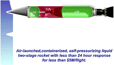
FIGURE E-1 QuickReach small launch vehicle. SOURCE: AirLaunch (2005).
The primary objective of an air launch is to be independent of fixed launch sites. Launch at altitude also reduces some of the drag losses associated with ground launch. Such a concept could favorably address the Air Force goal of responsiveness and would accommodate launch surge needs. It also provides alternatives to satisfy certain CONUS range constraints.
LOCKHEED MARTIN SPACE SYSTEMS COMPANY
Recent advances in hybrid propulsion—Hyperion, HYSR, and Space Ship One—have demonstrated a high TRL for suborbital applications. Lockheed Martin Space Systems Company (LMSSC), Michoud Operations, is working to advance hybrid propulsion technologies from suborbital to orbital applications.2 Its FALCON concept is based on a two-stage hybrid propulsion system that is capable of delivering a 1,000-lb payload to LEO from Cape Canaveral Air Force Base.
Launch vehicles that use hybrid propellant combinations containing an inert fuel gain the operational benefits of being nonexplosive. LMSSC said that the top three critical issues on the FALCON SLV program are to demonstrate that hybrid propulsion can achieve performance comparable to liquid systems, to demonstrate that such propulsion can satisfy mass fraction allocations, and to flight demonstrate the hybrid propulsion system in an orbital application (achieve TRL 8 or higher).
LMSSC predicts its various stage engines can operate at vacuum Isp values of 335-375 sec for area ratios from 17:1 to 140:1. Lessons learned from data on the precursors AMROC, HyTOP, JIRAD, and HPDP indicated that heat had to be added to the forward end of a hybrid motor to ensure stability and high efficiency. LMSSC developed and patented an active approach, the staged combustion system (U.S. Patent 5,794,435), to accomplish this task. To demonstrate the effectiveness of this concept, a series of tests was performed at chamber pressures around 500 psi and various thrust levels, from 1,500 lbf to 250,000 lbf. Comparison tests were also run on an unstable baseline test that was ignited using conventional triethylamine/triethylborane. The same motor was retrofitted with the staged-combustion system and performed significantly better, exhibiting stability within 2.5 percent of the average chamber pressure (typical solid propulsion stability is 5 percent of the average chamber pressure). As an
incremental step on the way to scaling the system to the 250,000 lbf motor, a test was planned to demonstrate the effectiveness of the staged-combustion system on a 24-in. diameter motor that was approximately 324 in. (24 ft) long. It was planned to turn off the staged-combustion system during the test to evaluate the effectiveness of the system. Data from testing indicate that the hybrid system is sufficiently stable and efficient to compete with liquid- and solid-based propulsion systems. The largest hybrid motor tested to date using the staged-combustion system was the HPDP 250,000-lbf motor, which was approximately 6 ft in diameter and 30 ft long. The motor was tested three times for a total burn duration of 80 sec. These tests demonstrated that the system could be successfully scaled to high-thrust motors that could be used for booster or first-stage applications.
In addition to stability and performance, LMSSC is developing technologies to decrease the physical size of hybrid propulsion systems. These technologies include energetic additives in the fuel grain, fuel with higher energy density, and multiple port configurations for increasing diameter.
MICROCOSM, INC.
Microcosm’s design concept for the FALCON SLV is the Eagle vehicle. Eagle is a three-stage vehicle. The main characteristics for all three stages are these: LOx/Jet-A propellants, pressure-fed system (using a tridyne-based high performance pressurization system), ablative chambers, triplet injector, composite tanks, and industrial-grade low-cost avionics. The first stage has six pods, each consisting of two 20,000-lbf thrust (vacuum) engines, for a total of 240,000 lbf thrust for the first stage. The second stage has one pod, two engines, and 40,000 lbf thrust. The 20,000-lbf engines used in Eagle are a derivative of the flight-proven 5,000-lbf engines. Microcosm has had two successful suborbital flights with the 5,000-lbf engines: one in 1999 with a single engine per pod and one in 2001 with two engines in a pod.
A first series of tests for the 20,000-lbf engine was successfully completed at AFRL at Edwards Air Force Base on May 22, 2005. The tridyne-based technology has been developed through IR&D and two contracts from the National Reconnaissance Office. Microcosm’s comprehensive analytical studies and experimental testing demonstrate the viability of this pressurization technology for a wide range of launch vehicle applications. The technology reduces the weight of the pressurization system by about 50 percent, resulting in a substantial increase in payload capacity. Microcosm is also working on developing all composite LOx and Jet-A tanks to enable pressure-fed systems to deliver meaningful payloads into orbit while keeping costs low.3 The tanks consist of a graphite composite liner with an embedded cryogenic sealant. This sealant prevents LOx from permeating into the carbon fiber through microcracks in the matrix. The liner is then over wrapped using the filament winding process. Microcosm will produce the first unit, but its sister manufacturing company, Scorpius Space Launch Company, is responsible for the production of subsequent vehicles.
Eagle’s technology could be used to deliver as much as 160,000 lb to LEO. This would be achieved by scaling up the vehicles and designing larger engines and tanks to carry greater payloads. The composite tanks can be scaled up to 12-18 ft in diameter, and the ablative engines can be increased in size to 640,000 lbf.
Microcosm has a simple operations plan that allows launch on demand from a simple flat pad virtually anywhere in the world. Some of Microcosm’s operational characteristics are as follows: air- and road-transportable launch system, pad crew of fewer than 12 persons, simple launch pad with fly-off interfaces, designed for launch in all but the very worst (99 percent launch reliability) weather, self-aligning Global Positioning System (GPS)/Inertial Navigation System guidance and navigation, no hypergols or explosive devices, and thrust-termination-based flight termination system with GPS tracking. Eagle has vertical vehicle integration, and the complete vehicle and its platform are put into flight-ready storage for call-up when needed.
SPACEX
SpaceX has its headquarters in El Segundo, California, and a 300-acre propulsion and structural testing facility in Texas. It is focused on improving both the cost and the reliability of access to space. The company has a flat hierarchy and small engineering teams, and the ratio of engineers to managers is high.
The development of Space X’s SLV for the FALCON program, also called the Falcon. The vehicle development is nearly complete. The Falcon’s maiden flight will be carrying a TacSat-1. It is expected to launch after the Titan IV lifts off from the Vandenberg Air Force Base (SpaceX, 2005). The SpaceX FALCON program is focused on a responsiveness demonstration scheduled for August 2005. The company’s payload integration process takes about 6 months. SpaceX uses a mobile launch infrastructure. It has a new and austere launch site and has decreased operations time from 21 to 10 days (SpaceX, 2005). The company proposes to meet the responsiveness criteria with a low-cost vehicle that has high availability and high reliability.
The Falcon vehicle has a payload capacity of about 1,400 lb to LEO. It launches from Vandenberg, Cape Canaveral, or Kwajalein and can attain any inclination. The vehicle has two stages with common domes. It has an aluminum monocoque structure. The first stage, which is pump fed, is slated to be recovered and reused. The second stage is pressure fed. The propellants are LOx/RP-1 for both stages.
To achieve high reliability, FALCON has a simple design. SpaceX exceeds in many ways the EELV testing requirements. Its manufacturing and inspection are based on a three-dimensional model. Also, the Falcon vehicle holds for 3 sec prior to launch at full thrust and does an automatic health check (SpaceX, 2005).
REFERENCES
AirLaunch. 2005. “2005 Responsive Space Conference,” Presentation to the 2005 Responsive Space Conference, April 25-28.
SpaceX. 2005. “The Falcon launch vehicle, achieving responsiveness requirements through high reliability and low cost,” Presentation to the 2005 Responsive Space Conference, April 25-28.


