In each of the four figures in this appendix, the bus work or node is depicted as a solid line. The squares represent circuit breakers that open the electrical circuit under load or short-circuit conditions. The switches, which have limited ability to interrupt current, serve to isolate components and bus sections.
MAIN AND TRANSFER BUS CONFIGURATION
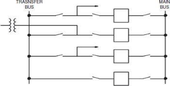
A main and transfer bus configuration consists of two independent buses, one of which, the main bus, is normally energized. Under normal operating conditions, all incoming and outgoing circuits are fed from the main bus through their associated circuit breakers and switches. If it becomes necessary to remove a circuit breaker from service for maintenance or repairs, circuit operation can be maintained through use of the isolating switches and bus transfer equipment. The circuit breaker to be maintained and its switches are opened, the bus transfer switches are closed, the switch from the transfer bus to the circuit is closed, and then the bus transfer breaker is closed to re-energize the circuit. The circuit is then protected by the bus transfer breaker. Figure F.1 shows the typical configuration of a main and transfer bus scheme.
The main advantages of this scheme include:
• Accommodation of circuit breaker maintenance while maintaining service and line protection;
• Low cost—essentially one breaker per line or transformer;
• Fairly small land area; and
• Easily expandable.
The primary disadvantages of this scheme include the following:
• Failure of a circuit breaker or a bus fault causes loss of the entire bus with outage of all circuits.
• An additional circuit breaker is required for bus tie.
• Since the bus tie breaker has to be able to be substituted for any line breaker, its associated relaying may be complicated.
• Complicated switching is required to remove a circuit breaker from service for maintenance.
The main and transfer bus scheme, which has the potential for a major outage of all circuits, is mainly used in older stations, most often at voltages of 230 kV and below. For large stations, the bus may be broken into two or three sections, with bus-sectionalizing circuit breakers. A bus fault or breaker failure then affects only one section of bus, with the opening of the sectionalizing breakers preventing outages on other bus sections. It is important to distribute circuits onto bus sections in a balanced way, so that sufficient transmission network conductivity remains with a bus section outage.

FIGURE F.1 One-line diagram of main and transfer bus scheme. In normal operation, the main bus is energized and the transfer bus is de-energized. In the bottom bay, the breaker and switches are open. In the top three bays, the switches on the left are open with the breakers and other switches closed.
BREAKER-AND-A-HALF CONFIGURATION
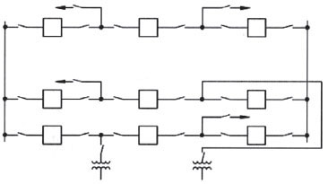
The breaker-and-a-half configuration, typically used at extra-high-voltage (EHV) stations, consists of two buses, each normally energized. Electrically connected between the buses are three circuit breakers and, between each two breakers, a circuit, as shown in Figure F.2. In this arrangement, three circuit breakers are used in a bay for two independent circuits; hence, each circuit shares the common center circuit breaker, so there are 1.5 circuit breakers per circuit. The breaker-and-a-half configuration provides for circuit breaker maintenance, since any breaker can be removed from service and isolated without interrupting any circuit. Additionally, faults on either of the main buses cause no circuit interruptions. Failure of a circuit breaker results in the loss of two circuits if a common breaker fails and only one circuit if an outside breaker fails. It is important to balance circuits in the bays, for example, source lines coming into the right-hand side of bays and load lines leaving the left-hand side of bays.
The main advantages of this scheme include the following:
• A bus fault does not interrupt service on any circuit, and circuit breaker failure causes loss of only one or two circuits;
• Flexible operation;
• High reliability; and
• Double feed to each circuit.
The primary disadvantages of this scheme include the following:
• One-and-a-half breakers are required per circuit;
• Relaying is complex, since the center breaker has to respond to faults of either of its associated circuits, and since currents from two sources must be measured for all circuits; and
• Each circuit must have its own potential source for relaying.

FIGURE F.2 One-line diagram of breaker-and-a-half bus configuration.

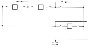
FIGURE F.3 One-line diagram for ring bus configuration.
RING BUS CONFIGURATION
For stations having three to five circuits, a ring bus is often used. As more circuits are added, the configuration may evolve to a breaker-and-a-half arrangement. Figure F.3 shows a three-circuit ring bus that is based on Figure F.2 but with the bottom bay and three breakers and one bay-two circuit removed. A maintenance outage of a circuit breaker or circuit causes an “Open ring.” For open-ring operation, a subsequent circuit outage may cause outage of additional circuits.
The advantages of this scheme include:
• Low cost—only one circuit breaker per circuit; and
• Flexibility to evolve to a breaker-and-a-half arrangements as more circuits are added.
The disadvantages of this scheme include:
• Reduced reliability in open-ring operation; and
• Temptation to add circuits without evolution to a breaker-and-a-half arrangement.
DOUBLE BREAKER-DOUBLE BUS CONFIGURATION
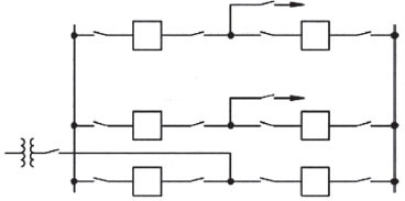
The double breaker-double bus configuration consists of two main buses, each normally energized. Electrically connected between the buses are two circuit breakers and, between the breakers, one circuit, as shown in Figure F.4. Two circuit breakers are required for each circuit.
In the double breaker-double bus configuration, any circuit breaker can be removed from service without interruption of any circuits. Faults on either of the main buses cause no circuit interruptions. Circuit breaker failure results in the loss of only one circuit.
Because of high cost, the double breaker-double bus configuration is usually limited to large generating stations. The additional reliability afforded by this arrangement over the breaker-and-a-half scheme usually cannot be justified for conventional transmission or distribution substations. Occasionally, at a generating station, one bay of a breaker-and-a-half arrangement is used as a double breaker-double

FIGURE F.4 One-line diagram of double breaker-double bus configuration.
bus arrangement for a generator terminal to provide equal access to either main bus.
The main advantages of this scheme include:
• Flexible operation,
• Very high reliability,
• Isolation of either main bus for maintenance without disrupting service,
• Isolation of any circuit breaker for maintenance without disrupting service,
• Double feed to each circuit,
• No interruption of service to any circuits from bus fault,
• Loss of only one circuit for breaker failure, and
• All switching with circuit breakers.
The primary disadvantage of this scheme is high cost because two circuit breakers are required for each circuit.


