
3
Vehicle Subsystems
The long-range goals of the FreedomCAR and Fuel Partnership—to transition to a transportation system that uses sustainable energy resources and produces minimal criteria or net carbon emissions on a life-cycle or source-to-wheels basis—are extremely ambitious. The difficulties are compounded when the additional constraints associated with the Partnership are imposed: energy freedom, environmental freedom, and vehicle freedom. These goals and associated constraints effectively eliminate the continued simple evolution of the gasoline-fueled internal combustion engine (ICE) vehicle as a possible answer. “Sustainable energy resources” and “energy freedom” both suggest non-petroleum-based alternative fuels or electricity. The emphasis on “net carbon emissions” and “environmental freedom” suggests that carbon dioxide (CO2) and other emissions from the production and consumption of alternative fuels or electricity should be reduced, through highly efficient processes, to minimize adverse environmental effects. Finally, “vehicle freedom” implies that the fuel and onboard energy conversion systems should not limit the options and choice that buyers expect to have available in their personal vehicles. These goals, if attained, are likely to require new transportation energy carriers (fuel[s] and/or electricity) utilized in more efficient power plants in lighter vehicles having reduced power requirements and equivalent utility and safety.
This chapter discusses the vehicle systems technology areas that the Partnership is addressing in its research and development (R&D) programs, which include the following: (1) advanced combustion, emission control, and fuels for ICEs; (2) fuel cells; (3) hydrogen storage on the vehicle; (4) electrochemical energy storage or technologies for storing electricity onboard a vehicle; (5) electrical propulsion systems; and (6) materials for reducing the weight of the vehicle. The
reader is referred to the presentations from the Partnership to the committee on the various technical areas: these can all be found in the project’s public access file, available through the National Academies Public Access Records Office. Chapter 4 will address issues associated with hydrogen and biomass-based fuels.
ADVANCED COMBUSTION, EMISSIONS CONTROL, AND HYDROCARBON FUELS
Introduction
Steady progress is being made in the advancement of power plants that rely on energy carriers other than liquid hydrocarbon (HC) fuels. However, one unique characteristic of mobility applications is that the energy being supplied to the power plant needs to be carried around with the vehicle. As weight and volume are important parameters in vehicle design and function, it is critical to have the highest possible energy per unit of mass and per unit of volume within the vehicle’s fuel system. Here, the fuel system includes all aspects of carrying the energy on the vehicle—that is, the fuel tank or containment system (battery pack, or hydride material) and supporting structures are included in this weight and volume assessment. On this basis, liquid HC fuels are very effective energy carriers for mobility systems.
Using the metrics of energy density (watt-hour per liter [Wh/L]) and specific energy (watt-hour per kilogram [Wh/kg]) of a vehicle’s complete fuel system highlights differences compared to conventional vehicles and the challenges of implementing alternative energy carriers to mobility systems. When one makes these comparisons, it is important to consider not only the energy density of the vehicle’s fuel system but also the efficiency of converting the energy carried on the vehicle to motive power (power that causes motion) at the wheels of the vehicle.
Liquid HC fuels have very high energy density and specific energy relative to batteries and hydrogen systems, but the efficiency of the ICE is typically lower than that of systems using electric motors and power electronics and fuel cell systems. Thus the concentrated effort to improve the engine and power-train efficiency is easily understood. However, the energy density and specific energy of liquid HC fuels is so great that even considering these efficiency differences, a typical vehicle carrying a liquid HC will have significantly higher capability than that of an electric or hydrogen-powered vehicle in terms of deliverable work to the wheels per unit of mass and volume of vehicle energy storage onboard the vehicle.
For example, comparing an ICE with an efficiency of 40 percent to a hydrogen fuel cell vehicle (HFCV)1 with an overall power-train efficiency of 65 percent results in a work capacity of the liquid-fueled ICE vehicle that is approximately
4.5 times higher per unit of volume of “fuel storage” and approximately 4 times higher per unit of mass of “fuel storage” than those of the HFCV. It seems likely that there will be certain applications, such as extended operation at higher loads or very long range transport, that will favor using a liquid HC as the on-vehicle energy carrier.
In addition, as new power plants with alternative energy carriers are developed, produced, and introduced into the market, there will be a significant time delay associated with their market penetration. As noted in Chapter 1, in the United States the vehicle fleet turnover in recent years is estimated to be about 15 years.2 Consequently the turnover time for completely new vehicle architectures to achieve significant market penetration will be measured in multiple decades (Bandivadekar et al., 2008; Weiss et al., 2000). During this transition the dominant power plant for mobility systems will continue to be ICE vehicles fueled with a hydrocarbon fuel (e.g., gasoline, diesel fuel, or biofuel).3
Consequently, it is important to maintain an active ICE and liquid fuels R&D program at all levels: industry, government laboratories, and academia, to expand the knowledge base to enable the development of technologies that can reduce the fuel consumption of transportation systems powered by ICEs. The near-term introduction of such technologies into existing production facilities will reduce the growth in transportation petroleum use during a transition to alternative power plants and power-train configurations. This is the focus of the Partnership’s advanced combustion and emission control (ACEC) technical team.
The overarching goals, technical targets, and program structure of the ACEC technical team are basically the same as reported in the Phase 2 review of the program (NRC, 2008). The technical team has established the following technical engine target goals for 2010:
-
Engine peak brake thermal efficiency (BTE): 45 percent
-
Nitrogen oxides (NOx) and particulate matter (PM) emissions: Tier 2 Bin 5 (T2B5)
-
Power-train cost: <$30/kW
The general focus of the ACEC technical team’s work to achieve these targets continues to be lean-burn, direct-injection engines for vehicles fueled by diesel, gasoline, and biofuel or other alternative fuels, provided appropriate carbon emission mitigation is accomplished during their production. Within this broad area specific foci include the following:
-
Low-temperature combustion (LTC)
-
Control
-
Expanding the load range
-
Coupling to fuel characteristics
-
Transient operation
-
Combustion mode switching
-
-
Aftertreatment
-
Diesel particulate filter (DPF) modeling
-
Lean NOx traps
-
Selective catalytic reduction (SCR) NOx reduction
-
Potential catalyst identification for HC NOx catalysis
-
-
Tool development
-
Improved computational fluid dynamic (CFD) capabilities
-
Improved diagnostics capabilities
-
Comparison of CFD and experiment
-
In this quest, all aspects of the engine and power train are under investigation. Individual subsystems and processes, such as injection systems, turbochargers, combustion chamber system optimization, the enhanced use of alternative combustion processes (such as low-temperature combustion) and exhaust-gas energy recovery, are actively being investigated. All aspects of the engine operation are being pursued. The electrification of auxiliaries, matching the engine operation to the fuel characteristics, and reducing friction through advanced lubricants are subjects of investigation. Advanced sensors and total power-train system optimization will be enablers for integrating alternative combustion processes into the engine operational map. This will enable optimal matching of the engine and the exhaust aftertreatment systems. In addition, improvements in the aftertreatment systems, particularly lean NOx systems, will be a critical component of meeting the technical team’s targets. Current exhaust-gas aftertreatment systems increase fuel consumption. More effective exhaust emission systems will have a double benefit. They will reduce the fuel consumption associated with their use, and they will allow the engine to be tuned differently with an attendant increase in efficiency.
Hydrogen-fueled ICEs have also been investigated. Such technology could allow a broader use of hydrogen within the transportation system and thus allow the implementation of a hydrogen infrastructure while chemical-electric conversion power plants penetrate the market. However, the hydrogen-fueled ICE vehicle will have similar energy density and specific energy constraints as those of an HFCV, described above.
In all these endeavors, the key hurdle continues to be detailed fundamental understanding of the chemical, thermal, and physical processes taking place within the power train and combustion system.
Good progress is being made by the ACEC technical team in meeting the technical targets. A peak thermal efficiency for an ICE of 43 percent has
been achieved. A peak engine efficiency of 45 percent has been achieved for a hydrogen-fueled ICE. The operational range for LTC has been enhanced through active cylinder valve actuation and intake boosting. The technical team reported achieving engine loads of 16 bar (1.6 MPa) indicated mean effective pressure (IMEP) with homogeneous charge compression ignition (HCCI) using a combination of exhaust-gas recirculation (EGR) and intake boost. Additional sensing devices are being developed and integrated into the engine cylinder and power train that facilitate better control of the in-cylinder conditions and power-train energy flow management, which is a necessity for the integration of LTC operation into the engine map.
To maximize the gains in reducing fuel consumption and emissions, every aspect of the ICE power train and aftertreatment system must be optimized for every operating condition in the vehicle’s duty cycle. This requires accurate control and manipulation of all engine control parameters for each operating condition. The fundamental research being performed by the ACEC technical team is generating the knowledge base necessary for the identification of how to optimize the combustion process at any operating condition. This understanding is being incorporated into detailed CFD simulations, which in turn accurately replicate the experimental results with minimum adjustable numerical tuning.
The predictive capabilities of the current CFD codes are very good. In fact, the codes are now being used to guide experiments and, more importantly, to identify the combination of engine control parameters that will optimize the engine and power-train performance at different operating conditions, including the use of different combinations of fuels. This is a significant technical accomplishment.
The simulation currently being used is KIVA III, developed by the U.S. Department of Energy (DOE). KIVA is an open-source-code program, which allows researchers to incorporate new understanding directly into the code for any aspect of the thermophysical processes occurring within the engine: for example, improved kinetic schemes for different fuel types, or new submodels that more accurately represent liquid fuel-combustion chamber surface interactions can be implemented into the code and then exercised for more detailed predictions of combustion results. However, KIVA III is more than 10 years old and lacks important, modern numerical technologies such as parallel computing. Having an up-to-date, open-source-code CFD program for researchers to use is a critical aspect of achieving the improvement potential of the ICE and aftertreatment power trains.
To conduct such a program successfully requires close coordination among industry, government laboratories, and academia. The ACEC technical team continues to do a good job with this close coordination. The organizational structure of the team’s activities involves memoranda of understanding (MOU) between companies and government laboratories, working group meetings, regular intergroup reviews, and an annual peer-reviewed research meeting. The technical team’s responses to the recommendation of the previous review were good (DOE, 2009c).
The energy companies continue to be engaged, and the program of Fuels for Advanced Combustion Engines (FACE), organized under the Coordinating Research Council (CRC), is supplying an important database on the impact of fuel characteristics on engine-emission processes and alternative combustion process facilitation.
The technical team has had difficulty specifically addressing its cost target. The team has assumed that the base engine cost will be $20/kW, and the incremental cost for the technology improvements, which includes enhanced aftertreatment, will be $10/kW. The team has not been able to confirm these estimates with public domain data. Consequently, it has adopted a strategy of determining the technical feasibility of the power train and aftertreatment system, and from there it will work on reducing costs by system improvements (i.e., reduce engine-out emissions, maximizing use of LTC, improving aftertreatment robustness to poisons and thermal degradation, reducing precious metal content).
Funding
The FY 2009 funding level for the ACEC technical team was $25.4 million, with the requested level for FY 2010 being $27 million: the funds appropriated for FY 2010 were $34 million. A breakdown of how the FY 2009 funding was dispersed among different organizations and technologies is shown in Figure 3-1.
Adjustments and New Issues
Since the National Research Council’s (NRC’s) Phase 2 review of the FreedomCAR and Fuel Partnership research program (NRC, 2008), changes in the country’s energy situation have occurred. The biofuels program has grown significantly. Estimates that up to 30 percent of U.S. liquid HC energy could be displaced by domestically produced biofuels have appeared in the literature.4 A genetically modified alga has attracted attention as a way to enhance the recycling of power plant’s CO2 emissions into a viable transportation fuel.5 The prospect of enhanced electric storage capacity has spurred the interest in plug-in hybrid electric vehicles (PHEVs). And, new, more stringent emission regulations for NOx and PM are scheduled to go into effect after 2010. All of these will impact the ACEC program.
The ACEC technical team has acknowledged these changes and addressed them in its future plans. For example, the team is now engaged in fundamental combustion, emission, and kinetic studies of fuel derived from biomass. This work
|
4 |
See for example <http://www.altdotenergy.com/2009/02/sandia-gm-study-finds-large-scale-biofuel-is-sustainable/>. |
|
5 |
See for example <http://www.exxonmobil.com/Corporate/energy_climate_con_vehicle_algae.aspx>. |
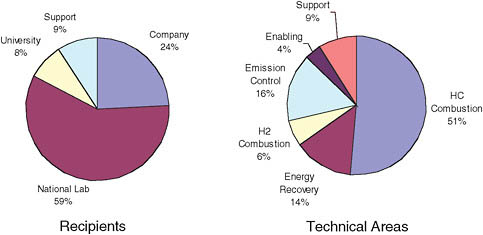
FIGURE 3-1 DOE advanced combustion engine research and development funding, FY 2009. SOURCE: Advanced Combustion and Emission Control Technical Team, Presentation to the committee, August 4, 2009, Southfield, Michigan.
is aimed at understanding the fundamental changes that occur in ignition and emission-formation processes when different compounds, such as methyl esters that are found in biofuels, are used in the engine. The auto-ignition characteristics of many oxygenates, which occur naturally in biofuels, may offer advantages in expanding the range of low-temperature combustion or in expanding the optimal-efficiency regions in engine maps.
The new emission standards will require that the vehicle emission target will need to be changed from Tier 2 Bin 5 to Tier 2 Bin 2. With this change will come new challenges in lean NOx aftertreatment, specifically mitigating the impact of sulfur poisoning and the associated degradation of the system performance that occurs with repeated desulfurization.
Pending fuel economy standards will impact the vehicle mix as the on-the-road light-duty vehicle fleet turns over. Vehicles will become smaller and lighter. Thus the requirements for the engines and power trains will change. For example, the optimal engine for a PHEV will be significantly smaller than the engines typical in vehicles today. All of these changes will force an evolution in engine and power-train design, and consequently, the optimal power-train configuration, operating scenario, and fuel characteristics will also evolve. It is likely that the operational targets for the engine and power train will become more fluid.
To the committee the foregoing considerations raised the question of whether system-level modeling could be used as a tool to evaluate the optimal power train, engine map, and fuel characteristics for different scenarios of vehicle, power train, and fuel mixes as the energy market and government regulation evolve.
Recommendations
Within the scope of the FreedomCAR and Fuel Partnership objectives, the funding level and work allocation for the continued development of the ICE and vehicle electrification seem appropriate. The ACEC technical team is doing a good job of maintaining a close and constructive working relationship with the stakeholders within the vehicle and energy community. It is critical for the technical team to maintain this collaboration and to look for ways to make it even stronger.
The largest barrier to implementing advanced combustion, aftertreatment, and fuel technologies continues to be an insufficient knowledge base. Not only topic-specific understanding but also an understanding of the system-level interactions among the energy carrier, the energy release process, and the final emission cleanup are critical to continued improvement of the ICE power train.6 Continued close collaboration between the DOE and industry is necessary to allow newly developed technologies to transition into the industrial laboratories and to lead to the identification of new areas where enhanced understanding will be the most beneficial.
Recommendation 3-1. The DOE should continue to support financially, be active in, and work to further enhance the collaborations among the national laboratories, industry, and academia in order most effectively to direct research efforts to areas where enhanced fundamental understanding is most needed to improve internal combustion engine and aftertreatment power-train performance.
Recommendation 3-2. The DOE should continue to support the development and dissemination of the open-source-code computational fluid dynamics program KIVA. This tool is critical to integrating the new understanding of combustion and emission processes into a framework that allows it to be used to guide further research and identify fuel and engine operating conditions that will maximize reductions in fuel consumption over the entire operating range of the engine.
Recommendation 3-3. The advanced combustion and emission control technical team should engage with the biofuels research community to ensure that the biofuels research which the team is conducting is consistent with and leverages the latest developments in the field of biofuels R&D.
Recommendation 3-4. As the vehicle mix within the on-the-road light-duty vehicle fleet is likely to change with the implementation of the new fuel economy standards, the advanced combustion and emission control technical team should
interface with the system modeling technical team to make sure that their research programs are consistent with the changing demands for the optimal matching of the engine operational regimes, power management, and emission control that will be imposed on the internal combustion engine and hybrid power trains as the vehicle characteristics evolve.
FUEL CELL SUBSYSTEM
The fuel cell power-generation subsystem—containing the fuel cell stack and its balance of plant (BoP) consisting of the supporting air and fuel supply, thermal management, and controls—is arguably the most complex and challenging element of the entire hydrogen-fueled vehicle. As this technology is not yet fully developed, advancements are needed to meet the established efficiency, durability, lifetime, and cost targets. Although there are multiple approaches and engineering configurations under development by the original equipment manufacturers (OEMs; the automobile manufacturers), the burden of successfully accomplishing all advancements by any one organization is challenging, since much of the effort is high-risk and demands the assignment of critical resources.
The Department of Energy has been proactive in providing fuel cell R&D support for the precompetitive scientific and engineering initiatives that are high-risk and enabling by providing funding to appropriate organizations such as universities, national laboratories, and the private sector. In many cases involving private-sector developers, R&D activities have the added benefit that the initiatives may lead to supply chain development. Such support has been available through the open solicitation process for nearly 8 years under this current program (FreedomCAR and Fuel Partnership) and a number of years prior in forerunner efforts such as the Partnership for the Next Generation of Vehicles (PNGV). The recent years have witnessed funding activities on fuel cells through multiple DOE organizations, including the Office of Energy Efficiency and Renewable Energy (EERE), Basic Energy Sciences (BES), the Small Business Innovation Research (SBIR) office, and more recently, with coordinated efforts with the National Energy Technology Laboratory (NETL) and the National Renewable Energy Laboratory (NREL). During this period, multiyear development programs have resulted in awards in support of fuel cell R&D efforts. In this program alone, the 8 years of funding has resulted in three cost-shared solicitations, resulting in many R&D contracts ranging from early programmatically focused efforts, to “go/no-go” milestone-based R&D. As a result of these programs, the core technology has advanced in such areas as fuel cell membranes, catalysts, operating modes, durability, lifetime, and the scientific evaluation of the factors limiting performance (e.g., gas quality), to name a few, while projected costs have continually decreased. The activities have been coordinated directly by the fuel cell technical team organized under the FreedomCAR and Fuel Partnership Executive Steering Group (ESG).
With respect to this review, since FY 2007 approximately $140 million (see Figure 3-2) has been appropriated in total to support the attainment of the fuel cell technology roadmap R&D (DOE, 2009a) objectives so that the Partnership’s chances of meeting the 2010 targets and the 2015 commercialization-readiness decision goal are enhanced. In order for this decision to be reasonably made (i.e., for the OEMs to decide by 2015 whether or not to initiate the next steps in the process of developing commercially viable vehicles based on a hydrogen fuel cell power-generation subsystem), much of the technology must be demonstrated to be operational in vehicles, or at least it must be significantly beyond laboratory scale. The attainment of, or progress toward, 2010 targets, as shown in Table 3-1 for selected fuel cell stack targets, can also be considered as a measure of progress of the program. The 2010 goals assessment is also a measure of ascertaining whether the R&D topics initially deemed to be the highest priority are still appropriate. In such cases, the DOE go/no-go decision-making process can be and is employed. The committee’s assessment is that the fuel cell technical team is well coordinated and is aligned with respect to the achievement of the goals and the longer-term, high-risk technology challenges, especially as the OEMs are now road testing prototype HFCVs.
In light of the prior funding of this program as reported in this review period (2007-2009) and the advancements reported to the committee, at the time of this assessment the success of the program could have been put in jeopardy as a result
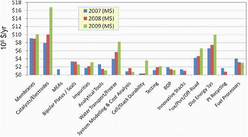
FIGURE 3-2 Fuel cell budget, FY 2007 through FY 2009 (in millions of dollars per year). SOURCE: C. Gittleman (GM) and K. Epping Martin (DOE), “FreedomCAR Fuel Cell Technical Team,” Presentation to the committee, August 4, 2009, Southfield, Michigan.
TABLE 3-1 Selected Fuel Cell Stack Targets and Progress
|
|
Currenta |
2010 Target |
2015 Target |
|
Lifetime (hr) |
1,977 |
|
5,000 |
|
Catalyst loading (mg/cm2) |
0.15 |
0.30 |
0.15 |
|
Efficiency at 25% rated power |
59%b |
60% |
60% |
|
Projected system costs (500,000 units produced per year; $/kW) |
~60-70 |
45 |
30 |
|
Power density (W/L) without storage |
224 |
|
325 |
|
Specific power (W/kg) without storage |
406 |
|
325 |
|
a As reported to the committee at its August 4-5, 2009, meeting and by S. Satyapal, DOE, Hydrogen Program Overview, Annual Merit Review and Peer Evaluation Meeting, May 18, 2009, Washington, D.C. Available on the Web at <http://www.hydrogen.energy.gov/pdfs/review09/program_overview_2009_amr.pdf>. b Based on laboratory results from 3M and not full-size modules. |
|||
of the zeroing of the primary budget line items related to the fuel cell development activities (in the FY 2010 administration’s budget request). If vehicle fuel cell development is to continue, such funding must remain intact and must be directed at the R&D that can help enable OEMs to develop the complete vehicle fuel cell power-generation subsystem. More specifically, as stated in its recommendations, the committee believes that technologies needed for vehicle fuel cell systems—and not just fuel cells for stationary, auxiliary power, or portable applications—should be pursued. Vehicle fuel cell requirements can be, and usually are, different and more challenging with respect to cost, reliability, and manufacturability when compared to the other nonvehicle applications. Furthermore, continued funding, especially of the high-risk concepts, will help facilitate next-generation technologies.
The fuel cell stack is composed of layers of catalyzed proton-conducting membranes and electrode assemblies (MEAs) that react supplied hydrogen fuel with oxygen from the air. The MEAs must operate under all environmental conditions and have nearly turnkey operating characteristics. The continued refinement of prior generations of the MEAs is a major issue, as neither the earlier nor current versions have been shown to meet simultaneously the 2015 targets for performance, lifetime, reliability, and cost. However, significant progress has been and continues to be made, as evidenced by field and laboratory testing. Table 3-1 presents selected fuel cell stack targets, the current status, and the progress against such targets as reported by the DOE and the Partnership. Even with such data, complicating the comprehensive understanding of the status of the fuel cell technology is the fact that the OEMs have their own respective (proprietary) fuel cell activities and engineering approaches, which may or may not be synchronized with the DOE-funded development efforts. With that said, what has been reported is that, overall, the OEMs have shown increased power density for the fuel cell stack and BoP, while at the same time the packaging and operating modes have become quite sophisticated. Manufacturing aspects of the power-generation
subsystem have yet to become a serious focus partly because of the continuing evolution of the technology (i.e., capital funding for fixed assets is not prudent when the technology may still change). Yet, selected subcomponent suppliers have prototype manufacturing capability today that would meet near-term demand. A noteworthy comment on significant achievements since the previous review is that, while almost every major target has been met in one form or another, they have unfortunately been in separate initiatives and not from a collective, single source. Although it is not definitive that the 2015 targets are achievable by the year 2015, the promising results to date indicate that they could be.
As the DOE programs address precompetitive R&D, it is important to point out again that the OEMs have their own proprietary engineering programs and are not obligated to incorporate DOE-funded developments and technologies into their units. As a result, aside from the open reporting of such performance data and improvements, the contributions of the publicly funded programs and the degree to which the results impact the success of the OEMs related to efficiency, durability, lifetime, and cost are not known with certainty.
Assessment of the Program and Key Achievements
Results reported from the recently funded activities indicate that the current fuel cell subsystem program is making significant progress, yet the successful attainment of the 2015 targets will not be known for some time. However, the attainment of the 2010 targets will be a very positive indicator of future success. Key achievements highlighted by the DOE and made since the Phase 2 review (NRC, 2008) are primarily performance- and cost-related: in particular, fuel cell stack technology tested under realistic on-road operating conditions. Demonstrated stack lifetimes in on-road vehicles have increased from operating times of approximately 1,250 hours to 1,977 hours.7 With the goal of 5,000 hours, this represents a significant achievement since the Phase 2 NRC review. Furthermore, single-cell and short-stack tests at the laboratory scale have demonstrated (using accelerated test protocols) much longer run times (3M Company, 7,200 hours)8 that, if demonstrated in vehicles under realistic on-road conditions, would meet or exceed the goals of the Partnership. Larger-scale stack performance and on-road testing will help to validate the laboratory data and determine the ultimate value to the program.
Cost (reduction) is the other area where significant advancements have been reported. The cost assessment of a fuel cell power plant is difficult to make, since the stack and BoP materials and system technology are still evolving.
|
7 |
See DOE’s Annual Merit Review on the Web at <http://www.hydrogen.energy.gov/annual_review.html>. |
|
8 |
See DOE’s 2009 Annual Merit Review, presentation by S. Satyapal, on the Web at <http://www.hydrogen.energy.gov/pdfs/review09/program_overview_2009_amr.pdf>. |
Furthermore, such component costs are not benefiting from established volume manufacturing operations at this time. To complicate the assessment of future cost further, the fuel cell stack is dependent on the platinum metals markets and on ever-changing global metals markets dynamics. In making cost projections, the assumptions are many and in some cases are based on still-unproven laboratory-phase performance. Although the results are encouraging, the same conclusion that was reached in the Phase 2 review (NRC, 2008) still holds: the cost projections are highly dependent on many unknowns and must have greater resolution in the forthcoming period. However, two separate DOE-funded studies, with independent oversight, have concluded that at volumes of 500,000 units per year, the cost per kilowatt for the fuel cell subsystem, including the fuel cell and BoP, will be approximately $60-$70/kW (Satyapal, 2009; James and Kalinoski, 2009; Sinha et al., 2009). These figures are still over two times higher than the target, but significantly lower than the $107/kW presented during the Phase 2 review. The projected cost is split nearly evenly between the stack and the BoP. Furthermore, within these cost assessments it was pointed out that platinum and membrane costs are still significant hindrances to stack cost reduction (currently active areas of DOE-funded efforts). Both stack and BoP cost reductions are required in order to achieve the $30/kW target. It was suggested by the cost studies that system simplification is essential to reduce the BoP cost.
Another measurement of progress is the number of granted patents related to FreedomCAR technology which have been derived from DOE funding. Such a metric is indicative of technology that is in the marketplace today or is available for commercialization. It impacts the fuel cell developers as well as the supply chain. As reported in a Pacific Northwest National Laboratory (PNNL) report prepared for the DOE on the patents originated from the Hydrogen, Fuel Cells and Infrastructure Technologies (HFCIT) program (DOE, 2009d), of the 144 patents, 70 have been issued since 2002 when the FreedomCAR program was initiated. Such patents have been awarded to universities, the private sector, and the national laboratories, and they represent inventions in all segments of the technology.
A particular subcomponent impacting the fuel cell cost and lifetime is the membrane and electrode assembly. Catalyst quantities required to support the hydrogen and oxygen reaction also contribute to both metrics. The lower catalyst loadings, although attractive from a cost perspective, introduce a greater risk of negatively impacting performance. The lower the catalyst loadings, the greater the potential impact on performance. Loadings as low as 0.2 mg/cm2 have been reported in full-size modules, yet the direct impact on life is not clear at this time. The ability to achieve less than 20 grams of precious metal per 80 kW stack has been verified in the laboratory but has not yet been demonstrated in a vehicle. Progress in other MEA areas has been mixed. Current membranes have a greater degree of robustness but are still impacted by secondary reactions, which can lead to chemical attack and therefore failure. Newer, lower-cost membrane development activities have been funded in recent years, and although the results of such
work look promising, it is unclear if they will lead to significant improvements in stability, life, and cost.
Overall, within this last period of activity and considering that the results available for assessments stem from 2001-2008 activities, much progress has been made in key areas. However, the coordination of the program (targets) by the fuel cell technical team could be reevaluated in some areas, such as the following:
-
The system being modeled by the Argonne National Laboratory (ANL) and used for costing efforts by the two cost contractors is not equivalent to the system expected to be under test for the 2010 goals assessment or the 2015 commercialization-readiness decision. Even though the DOE uses the system model principally for the purpose of costing and not system performance, the model should be representative of the actual system. As a specific example of the disparity, the costing was performed using a two-stack configuration, although even in the 2010 goals-assessment configuration it is expected that there will be a single stack.
-
On-road vehicle operation and performance trials have proven to be invaluable in uncovering unanticipated problems and verifying operation, and yet there is no plan to continue the funding for this activity.
-
As the majority of on-road vehicles were tested in moderate climates, additional assessments of performance in all-weather conditions are needed to provide additional insight into the viability of the current technology path.
Significant Barriers and Issues That Need to Be Addressed
The barriers remaining for the fuel cell subsystem R&D program are both programmatic and technical. Programmatic issues relate to the coordination and execution of the high-risk research in order that the solicitation timing and content address updated requirements of the Partnership.
Technical barriers that still remain for the fuel cell stack are membrane and electrode life and cost. Both areas must remain the focus of the next round of solicitations. Further, as indicated in the preceding discussion on cost, system simplification is essential to cost reduction.
Response to Phase 2 Recommendations
The Partnership addressed and concurred with the majority of the recommendations from the National Research Council’s Phase 2 review (DOE, 2009c; NRC, 2008). In some instances the FY 2009 DOE budget reflects such recommendations, and the Partnership continued to be proactive in specific areas highlighted in the Phase 2 report. In particular, the focus on advanced membranes and
catalysts to address the cost, reliability, and durability challenges is reflected in the current budget.
Appropriate Federal Role
The committee believes that federal funding for fuel cell activities is appropriate and that it remains extremely important, especially for the high-risk-related technical barriers. The need will be reduced, however, as the OEMs move closer to a commercialization phase and as the companies lock in designs for their engineering solutions. New concepts, cost-reduction R&D, and alternative engineering approaches must remain the focus of the DOE funding, especially for the development of next-generation technologies. This is especially important because numerous subsystems are interrelated. Furthermore, supply chain R&D and manufacturing concepts might require funding for the high-risk initiatives.
As the number of potential vehicle fuel cell manufacturers has been reduced in the current (2009) time frame, it is extremely important to maintain continuity and commitment regarding fuel cell technology from the perspective of the United States. As European and Asian car manufacturers are announcing fuel cell vehicle commercialization target dates in the 2015 time frame, the role that the DOE plays in supporting the FreedomCAR and Fuel Partnership has become even more critical.
Conclusions and Observations
Technology has advanced since the NRC Phase 2 review, and it is progressing even in spite of the current economic and automotive industry challenges. Together with the DOE, the OEMs with their proprietary engineering advancements have reported significant on-road achievements toward the 5,000-hour reliability and durability target. Although it is difficult to assess the specific technologies adopted by the OEMs, and the origins of the technologies, the degree of success is apparent.
The core stack technology advancement appears to be one of the most significant achievements reported to date. Although the current approach is very promising, there is a risk that down-selection of any one specific technology might be premature. Backup and secondary approaches must be in place, especially with respect to the high-risk elements.
Results to date indicate that most of the 2010 fuel cell performance targets are going to be met. The attainment of the majority of the 2015 targets is still difficult to predict.
The coordination of activities between the fuel cell technical team members and the DOE appears functional and focused. Yet, because of the nature of the DOE multiyear funded solicitation process and the rapid advancements by the OEMs, there can be a divergence of the currently funded efforts and the fuel cell subsystem R&D needs.
Recommendations
Recommendation 3-5. As the auto companies begin to down-select technologies for fuel cell vehicles, they must focus their limited R&D resources on development engineering for the platform selected and move into the competitive (as distinct from precompetitive) arena. The only way that alternative fuel cell systems and components can receive sufficient attention to mitigate the overall program risk is for the precompetitive program, sponsored largely by the DOE, to support them. Thus, the DOE should increase its focus on precompetitive R&D related to both the fuel cell stack and the balance of plant—the other components of the fuel cell system required for successful operation, such as controls, fuel storage, instrumentation, and so forth—to develop alternatives to the down-selected technologies.
Recommendation 3-6. The DOE should incorporate more of the advanced, most recent, nonproprietary OEM system configuration specifications in the various systems and cost models for fuel cell power plants. Systems configurations no longer demonstrated to be optimal should be abandoned in favor of best proven technology.
Recommendation 3-7. The DOE should establish backup technology paths, in particular for stack operation modes and stack components, with the fuel cell technical team to address the case of current technology selections determined not likely to meet the targets. The DOE should assess which critical technology development efforts are not yielding sufficient progress and ensure that adequate levels of support for alternative pathways are in place.
Recommendation 3-8. The DOE, with input from the fuel cell technical team, should evaluate, and in selected cases accelerate, the timing of the “go/no-go” decisions when it is evident that significant technological progress has been made and adopted by the OEMs.
ONBOARD HYDROGEN STORAGE
Background
Onboard hydrogen storage is a key enabler for fuel-cell-powered vehicles. The primary focus of the hydrogen storage program within the FreedomCAR and Fuel Partnership is to drive the development and demonstration of commercially viable hydrogen storage technologies for transportation and stationary applications. A specific goal of the program is a vehicle driving range of greater than 300 miles between refuelings while simultaneously meeting vehicle packaging, cost, and performance requirements. The program also includes life-cycle issues, energy efficiencies, safety, and the environmental impact of the applied hydrogen storage technologies.
The primary focus of the program is exploratory materials concepts for onboard storage with the potential to meet the long-term goals. Issues for high-pressure tanks that may have nearer-term application and can benefit from exploratory research are also included. Concepts developed in this program could potentially benefit all hydrogen storage applications.
The work of the onboard hydrogen storage program is organized in four centers of excellence (COEs): the Chemical Hydrogen Storage COE, the Hydrogen Sorption COE, the Metal Hydrides COE, and the Hydrogen Storage Engineering COE (see Table 3-2 and Figure 3-3). In 2009, DOE-funded activities in hydrogen storage, including Office of Science Basic Energy Sciences awards, were carried out at 41 universities, 15 companies, and 14 federal laboratories. The hydrogen storage technical team and the DOE provide guidance for the work of the COEs. The program also includes several independent projects that are not associated with any of the COEs (see Figure 3-3). The hydrogen storage technical team is a joint technical team with participants from both the automotive and the fuel industries.
The four COEs and the independent projects constitute the framework of the National Hydrogen Storage Project (see Box 3-1 and Figure 3-3). The independent research projects explore promising hydrogen storage materials and concepts, off-board hydrogen storage for hydrogen delivery, the standardized testing of hydrogen storage properties, and analyses of life-cycle cost, energy efficiency, and environmental impact for hydrogen storage systems.
The EERE hydrogen technology budget appropriation for hydrogen storage was $59.2 million in FY 2009, which was 36 percent above the FY 2008 appropriation ($43.5 million) for applied hydrogen storage research (see Table 3-3). The FY 2010 EERE appropriation for hydrogen storage is $32.0 million. This reduced funding versus FY 2009 will meet existing grant commitments but provides no new starts. The BES budget within the Office of Science also included support of Basic Energy Research Needs for the Hydrogen Economy ($38.3 million in FY 2009). Novel materials for hydrogen storage were a high-priority area for BES funding, receiving $8.0 million in FY 2008 and $9.0 million in FY 2009.
Hydrogen storage has been an R&D priority for the DOE for less than a decade. The committee believes that continued activity with adequate R&D funding should be provided for material-based storage in order to increase the marketability of HFCVs. New focus and funding should be given to compressed-gas storage in order to meet near-term needs for hydrogen storage.
Current Status Vis-à-Vis Goals and System Targets
The physical storage of hydrogen on vehicles as compressed gas (and to a lesser extent liquid hydrogen) has emerged as the technology path for the early introduction of HFCVs. The hydrogen storage capacity of tanks is performance limiting for some vehicle architectures, but hydrogen storage overall is not a
TABLE 3-2 Centers of Excellence (COEs) Project Focus and Participating Organizations
|
COE |
Project Focus |
Organizations |
|
Center of Excellence on Chemical Hydrogen Storage |
New chemical hydrogen storage materials and regeneration processes, including ammonia borane, ionic liquids, heteroatom containing organics, catalytic processes, and new concepts for hydrogen release and spent-fuel regeneration. |
Los Alamos National Laboratory, Pacific Northwest National Laboratory, Intematix Corporation, Millennium Cell, Northern Arizona University, Pennsylvania State University, Rohm and Haas, Inc., University of Alabama, University of California-Davis, University of Missouri, University of Pennsylvania, University of Washington, US Borax |
|
Center of Excellence on Hydrogen Sorption |
High surface area sorbents including metal-carbon hybrids, boron-carbon materials, metal organic frameworks, nanohorns and fibers, conducting and porous polymers; modeling and mechanistic understanding |
National Renewable Energy Laboratory, Air Products and Chemicals, Inc., California Institute of Technology, Duke University, Lawrence Livermore National Laboratory, National Institute of Standards and Technology, Oak Ridge National Laboratory, Pennsylvania State University, Rice University, University of Michigan, University of North Carolina, University of Pennsylvania |
|
Center of Excellence on Metal Hydrides |
Light-weight complex hydrides, destabilized binary hydrides, intermetallic hydrides, modified lithium amides, and other advanced onboard reversible hydrides |
Sandia National Laboratories-Livermore, Brookhaven National Laboratory, California Institute of Technology, General Electric, HRL Laboratories, Intematix Corporation, Jet Propulsion Laboratory, National Institute of Standards and Technology, Oak Ridge National Laboratory, Savannah River National Laboratory, Stanford University, University of Hawaii, University of Illinois at Urbana-Champaign, University of Nevada-Reno, University of Pittsburgh/Carnegie Mellon University, University of Utah |
|
Hydrogen Storage Engineering Center of Excellence |
Energy challenges associated with developing low-pressure material-based hydrogen storage systems for enabling onboard storage of hydrogen for fuel-cell-powered vehicles and for achieving customer expected driving range and performance. (Includes systems integration, prototype development, and systems analysis.) |
Savannah River National Laboratory, Pacific Northwest National Laboratory, United Technologies Research Center, Los Alamos National Laboratory, NASA Jet Propulsion Laboratory, National Renewable Energy Laboratory, General Motors Company, Ford Motor Company, Oregon State University, Lincoln Composites, Inc. |
|
SOURCE: DOE (2009a), Section 3.3, Hydrogen Storage. |
||
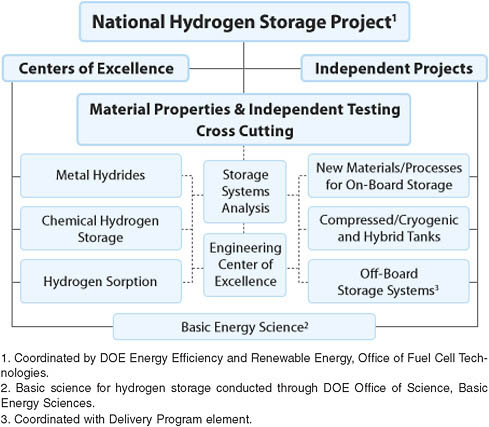
FIGURE 3-3 Structure of the National Hydrogen Storage Project. SOURCE: Reprinted from DOE (2009a).
TABLE 3-3 Office of Energy Efficiency and Renewable Energy Budget Appropriations for Hydrogen Storage, FY 2007 through FY 2010 (millions of dollars)
|
Fiscal Year |
Appropriation ($ millions) |
|
2007 |
33.7 |
|
2008 |
43.5 |
|
2009 |
59.2 |
|
2010 |
32.0 |
|
SOURCE: A. Sudik, F. Bavarian, and N. Stetson, Hydrogen Storage Joint Technical Team, Presentation to the committee, August 5, 2009, Southfield, Michigan. |
|
“blocking” technology for vehicle introduction. The storage capacity of current tanks does not meet the long-term goals, but it may be adequate for some applications for which the cost can be justified. Thus, research aimed at significantly higher hydrogen storage capability needs to be kept as a research objective. Materials-based storage at the level required to meet all program targets is considered theoretically achievable, yet no material has been identified that meets all of the targets. These results are promising but will not be achieved without adequate funding, which is required to continue to make progress and to attract outstanding scientists and engineers to this line of research. All targets (weight, volume, efficiency, cost, packaging, safety, refueling ability, etc.) must be met simultaneously. The discovery and development of materials for onboard hydrogen storage remain high-technical-risk R&D in need of research attention and government funding.
The targets and timing for the onboard hydrogen storage program were revised since the Phase 2 review to reflect the knowledge gained from real-world vehicle experience and the vehicle weight and space appropriate for market penetration. The revised targets assume that the vehicle architecture will change between gasoline ICE and HFCVs. The newly revised hydrogen storage targets are shown in Table 3A-1 in the annex at the end of this chapter.
The overall objective for hydrogen storage remains unchanged except for the targets: vehicle performance across vehicle models with acceptable driving range, packaging, and cost, while meeting all safety requirements. Hydrogen storage capacity and cost are key parameters for initial materials evaluation. The revised targets are as follows:
-
By 2010, develop and verify onboard hydrogen storage systems achieving (old targets) 2 kWh/kg (6 weight percent [wt%]), 1.5 kWh/L, and $4/kWh; (new targets) 1.5 kWh/kg (4.5 wt%), 0.9 kWh/L (28 g/L).
-
By 2015, develop and verify onboard hydrogen storage systems achieving (old targets) 3 kWh/kg (9 wt%), 2.7 kWh/L, and $2/kWh; (new
-
targets) 1.8 kWh/kg (5.5 wt%), 1.3 kWh/L (40 g/L). (See “Annex to Onboard Hydrogen Storage” at the end of this chapter.)
Since the Phase 2 review, more than 350 materials approaches for hydrogen storage were investigated, of which 68 percent have been discontinued and 32 percent are still under investigation. Twenty-one hydrogen storage patents were issued. To date no material for onboard hydrogen storage has been identified that meets the full set of 2015 targets. These system targets are listed in the annex to this chapter.
Milestones achieved since the Phase 2 NRC (2008) review include the following:
-
The no-go decision made for vehicle hydrogen storage during the Phase 2 review was to discontinue applied R&D in pure, undoped, single-walled carbon nanotubes based on the fact that they were not able to meet the storage target of 6 wt% close to room temperature (2006).
-
A no-go decision was made for sodium borohydride onboard vehicular hydrogen storage (2007).
-
The Multiyear Research, Development, and Demonstration Plan was developed for the years 2005-2015 (2007).
-
A Hydrogen Storage Engineering Center funding opportunity was announced (2008).
-
The down-select decision on chemical hydrogen storage materials was made (2008). Selection criteria were established (e.g., gravimetric capacity, potential to regenerate onboard, regenerable, acceptable phase change, H2 release rate materials stability, endothermic release, H2 release temperature). Of 120 materials and classes of materials examined to date, 15 percent were selected for continued study.
-
Metal hydrides materials were down-selected. Selection criteria were established based on the potential to meet 2010 technical targets. Of 74 materials investigated to date, 40 have been selected for further work.
-
The Hydrogen Sorption COE has investigated 160 materials, and 35 percent are still in its inventory. A down-select report is in preparation.
-
The announcement of the Hydrogen Storage Engineering COE (2009) was made. This COE will address system integration and prototype development in coordination with the materials centers. It was awarded to the Savannah River National Laboratory (SRNL).
-
An H-Prize competition notice was issued for “Breakthrough Advances in Materials for Hydrogen Storage” (DOE, 2009b). A single amount of $1 million will be awarded for the development of an onboard hydrogen storage material that meets or exceeds a set of performance targets specified in the competition announcement. This prize creates an incentive for the R&D community outside the conventional grant process.
-
A DOE hydrogen program solicitation was issued for R&D for onboard vehicular hydrogen storage to support the COE or as independent projects (2008).
Assessment of Progress and Key Achievements
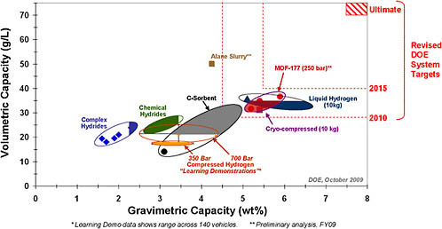
The current status of promising hydrogen storage materials is shown in the composite Figure 3-4. Hydrogen storage is shown together with the new targets (volumetric and gravimetric capacity only). Figure 3-4 shows results for the three groups of hydrogen storage materials: complex hydrides, chemical hydrides, and carbon sorbents. Data given here show that all three material groups fall short of the 2015 system targets for both volumetric and gravimetric capacities, but with best results demonstrated for the carbon sorbents.
The current candidate storage materials under investigation for the three classes of materials—reversible metal hydrides, chemical storage materials, and hydrogen sorbents—are listed in Box 3-2.
Information for physical storage is shown in Figure 3-4 for both ambient and cryo-based systems. Data are shown for 350 and 700 bar (ca. 35 MPa and 70 MPa) compressed hydrogen. In the nearer term, ambient physical storage provides a means for advancing the integrated hydrogen fuel cell system development and gaining experience while the materials storage approach is developed further. The ambient systems (the current and simplest configuration) are targeted for the early introduction of the vehicle test fleets.
Expensive “aerospace quality” carbon fiber is needed in the construction of the onboard pressure vessel for hydrogen for HFCVs. Such fibers provide the necessary high strength and lightweight characteristics. The DOE currently has several efforts to reduce the cost of carbon-fiber pressure vessels. Included in these efforts is the use of melt spinning in place of the currently used solution spinning of the PAN (polyacrylonitrile) feedstock. Another project that has promise for cost reduction is the hot-melt processing of PAN. Quantum Technologies is also being funded to reduce the cost of compressed storage by manufacturing process optimization. Also, a carbon-fiber pilot line facility is being funded with American Recovery and Reinvestment Act (ARRA) of 2009 funds at the Oak Ridge National Laboratory to lower the processing and feedstock costs for aerospace-quality fibers.
Two reports, one on cryo-compressed hydrogen (ANL, 2009) and one on compressed hydrogen (TIAX, 2009), released in late 2009, project that the cryo-compressed tank as modeled will meet the gravimetric targets for hydrogen storage but not the volumetric targets. For the compressed hydrogen study, the 350 and 700 bar (ca. 35 MPa and 70 MPa) tanks as modeled will meet the gravimetric targets but none of the volumetric and cost targets. These projections include the balance of plant.
Although the storage density is a critical parameter, all of the targets (weight, volume, efficiency, cost, packaging, safety, refueling ability and time, etc.) must
|
BOX 3-2 Current Candidate Hydrogen Storage Materials Under Investigation
|
|||||||||
be met simultaneously. None of the approaches (neither material-based nor physical storage) meets the combined targets. The program approach of using the Hydrogen Storage Engineering COE to fabricate and evaluate complete vehicle-ready test systems is an excellent technique for selecting the most viable material configuration. The material and physical storage results to date (obtained in a short time) as well as the Hydrogen Storage Engineering COE are promising with respect to the attainment of the 2015 objectives.
Also of note, the DOE Vehicle/Infrastructure Demonstration Program reported having achieved an HFCV range of 196 to 254 miles. The highest HFCV range reported to date (estimated to be 431 miles on a single full tank of compressed gas from Toyota) is the result of a field evaluation for a fuel cell hybrid vehicle. This field test included data analysis by NREL and SRNL through a collaborative research and development agreement (CRADA).
Highlights of Technical Accomplishments
Several significant technical accomplishments have been achieved, as follows:
-
Overall progress in system capacity is reported to have increased 50 percent since 2007.
-
Systems analysis of hydrogen storage options has been accomplished (Argonne National Laboratory).
-
Areas have been identified for materials-based and physical/compressed storage-system cost reduction (TIAX LLC).
-
MB12H12 effects on borohydride reversibility have been studied (NASA Jet Propulsion Laboratory [JPL], California Institute of Technology, and General Electric).
-
Alane regeneration has been achieved by means of adduct (Brookhaven National Laboratory).
-
Ammonia borane regeneration efficiency and yields have improved (COE on Chemical Hydrogen Storage).
-
Hydrogen binding energy on adsorbents has been increased (University of California, Berkeley; University of California, Santa Barbara; and Texas A&M).
-
Improved hydride kinetics by means of carbon aerogel scaffolds has been achieved (HRL Laboratories, LLC; and Lawrence Livermore National Laboratory).
-
A subscale prototype has been developed for NaAlH4.
-
A full-scale prototype has been developed for cryo-compressed hydrogen storage.
Significant Barriers and Issues That Need to Be Addressed
The hydrogen storage program has good recognition of the many technical needs and challenges that it faces. The following is a compilation of these issues:
-
Those common to all storage approaches
-
System weight and volume: Too high for meeting the 300-mile range across a wide spectrum of vehicle platforms. Basically no suitable storage material has been identified and developed.
-
System cost: Needs to be reduced compared with petroleum. Cost areas include materials of construction and manufacturing methods, and balance of plant components.
-
Charging time (refueling) for material storage: Storage capacity and rates of sorption and release need understanding and improvement (goal is 3 minutes for 5 kg charge).
-
Energy efficiency: Charging and discharging of hydrogen to a storage tank or storage material can be an energy consumer (requiring heating and/or cooling), which impacts the overall system efficiency.
-
Systems issues: Thermal management, durability and operability, hydrogen quality, containment vessels, dispensing technologies, and system life-cycle assessment and prediction need to be addressed.
-
Codes and standards: Needed for entire system and for all interfaces.
-
Safety: Issues related to hydrogen storage (see Recommendations 2-2 and 3-10).
-
-
Reversible materials-based systems (reversible onboard)
-
Hydrogen sorption (physisorption and chemisorption) and desorption processes: Understanding of these processes is needed.
-
Reproducibility of performance: Needs to be demonstrated.
-
-
Chemical hydrogen storage systems (typically regenerated off-board)
-
Regeneration process: Process cost, efficiency, environmental impact.
-
By-product/spent material removal: Important issues to be addressed.
-
-
Pressurized hydrogen storage tanks
-
The cost of high-quality carbon fibers: Needs to be reduced.
-
Technical tasks have been established that address each of these issues.
Future Plans
The newly organized Hydrogen Storage Engineering COE has taken on the coordination of the engineering aspects of material-based hydrogen storage systems. This center plans crosscutting hydrogen storage activities organized across six areas: performance analysis, system modeling, enabling technologies, materials operating requirements, transport phenomenon, and subscale prototype construction and testing and evaluation. Given the fact that the completion dates for the other three COEs and a number of independent projects fall within FY 2010, this COE will have a critical role in capturing the progress for a sustained activity during any transition period.
Target dates have been appropriately set for technology down-select decisions:
-
A complete analysis of onboard storage options for 2010 and 2015 targets was scheduled for 2009 as well as a decision point on advanced carbon-based materials and a down-select for chemical hydrogen storage approaches for the 2010 targets.
-
A decision on reversible metal hydride R&D is scheduled to be made in the fourth quarter of 2010 as well as a decision point on chemical hydrogen storage R&D.
-
The down-select for onboard reversible hydrogen storage materials and for chemical hydrogen storage approaches with the potential to meet 2015 targets is set for the fourth quarter of 2013.
-
Complete laboratory-scale prototype system and evaluation against 2015 targets is scheduled for the fourth quarter of 2015.
Future plans include continued R&D on breakthrough hydrogen storage materials with increased emphasis on engineering analysis, a broadening of the effort to include all of the targets (versus just the capacity targets), and increased coordination between the basic and applied activities. Early market applications will
receive increased emphasis. The hydrogen storage technical team will continue to monitor and leverage globally activities on hydrogen storage. In order to address the fuel storage needs of and to set priorities for fuel cell applications, the EERE plans to conduct a Request for Information (RFI) and a workshop during FY 2010.
Response to Recommendations from the Phase 2 Review
The DOE agreed with most of the recommendations from the Phase 2 review (DOE, 2009c; NRC, 2008). It did not address in the response the safety implications of relying on compressed-gas storage in the interim period. Compressed-gas tank safety needs further attention. The FY 2009 budget appropriation allowed the program to be supported at a high level for continuing and new R&D activities. The program has been managed to balance resources—for example, to cut storage approaches without potential and to down-select approaches with the most potential. The Hydrogen Storage Engineering COE is a timely use of resources and fits well with the other COEs. The real-world experience with pressurized tanks is providing information on R&D issues. The DOE (2009c) stated in the response that the issue of materials for pressurized tanks is being addressed in other parts of the program and in future solicitations. In response to the recommendation for a strong basic research portfolio, it was noted that BES held a contractors’ meeting for principal investigators funded on projects related to the Partnership in conjunction with the DOE Hydrogen Program Annual Merit Review and Peer Evaluation Meeting in 2006 and again in 2009. Hydrogen basic research is well funded in the FY 2009 program, and new concepts will continue to be supported.
Appropriate Federal Role
The federal sponsorship of the hydrogen storage activities within the FreedomCAR and Fuel Partnership is an appropriate federal role. The research work supported is high-risk and potentially important for meeting national energy and emission objectives. This sponsorship has significantly stimulated research and aided the advancement of the field through its support of a significant number of qualified researchers, providing focus on common goals, maintaining communications among participants, and peer review of results.
Recommendations
Recommendation 3-9. The centers of excellence are well managed and have provided an excellent approach for organizing and managing a large, diverse research activity with many participants at various locations. Measures should be taken to continue research on the most promising approaches for onboard hydrogen storage materials. The complete documentation and communication of
findings should be undertaken for all materials examined for the completed R&D. Furthermore, in view of the fact that the hydrogen storage program has been in place for less than a decade, the Partnership should strongly support continuing the funding of basic research activities. Public domain contractor reports should be available through links on the DOE EERE Web site.
Recommendation 3-10. Research on compressed-gas storage should be expanded to include safety-related activities that determine cost and/or weight, such as validation of the design point for burst pressure ratio at beginning of life and end of life and evaluation of Type 3 versus Type 4 storage vessels. Furthermore, finite-element modeling of stresses and heat flow in fires, investigative work on wraps (i.e., translation efficiency), and analysis of applicability of compressed-gas storage to specific vehicle types would be beneficial.
Recommendation 3-11. The high cost of aerospace-quality carbon fiber is a major impediment to achieving cost-effective compressed-hydrogen storage. The reduction of fiber cost and the use of alternative fibers should be a major focus for the future. Systems analysis methodology should be applied to needed critical cost reductions.
Recommendation 3-12. The hydrogen storage program is one of the most critical parts of the hydrogen/fuel cell vehicle part of the FreedomCAR and Fuel Partnership—both for physical (compressed gas) and for materials storage. It should continue to be funded, especially the systems-level work in the Hydrogen Storage Engineering COE. Efforts should also be directed to compressed-gas storage to help achieve weight and cost reduction while maintaining safety.
Recommendation 3-13. The time for charging the hydrogen storage material with hydrogen (refueling time) is a program goal (3 minutes for a 5 kg charge). Concepts beyond materials properties alone should be explored to meet this challenge for customer satisfaction, and will require coordination with the areas of production, off-board storage, and dispensing.
Recommendation 3-14. There should be an effort to anticipate hydrogen storage material property and performance requirements that will place demands on developed systems—for example, purity and response to impurities, aging and lifetime prediction, and safety in adverse environments. Linkage between the hydrogen storage and production and delivery activities should receive attention.
Recommendation 3-15. The search for suitable onboard hydrogen storage materials has been broadly based, and significant progress is reported. Nonetheless the current materials are not close to the long-range goals of the Partnership. Onboard hydrogen storage R&D risks losing out to near-term applications for
future emphasis and funding. The management of a long-term/short-term joint portfolio should be given consideration.
ELECTROCHEMICAL ENERGY STORAGE
Introduction
Electrochemical energy storage technologies, batteries, and ultracapacitors are critical to the advancement of the FreedomCAR and Fuel Partnership’s long-term goals. Significant improvement in their performance can result in battery electric vehicles (BEVs), one of the ways to meet the Partnership’s goal of “energy freedom, environmental freedom, and vehicle freedom.” The FreedomCAR and Vehicle Technologies (FCVT) program (now renamed the Vehicle Technologies [VT] program), has supported the advancement of batteries and ultracapacitors from the beginning as a key to developing hybrid electric vehicles (HEVs). Also, before a hydrogen fuel infrastructure is fully developed, plug-in hybrid electric vehicle (PHEV) and BEV technologies, which would compete with hydrogen fuel cell vehicles, may offer a transitional means to improve fuel efficiency and emissions reduction. Since the success of HFCVs is not assured, this transition role could turn out in many cases to be a more permanent scenario.
In 2006, in response to the President’s Advanced Energy Initiative, the FCVT program began the development of PHEVs, or extended-range electric vehicles. In contrast to conventional vehicles or HEVs, PHEVs are able to drive on electric power alone for some distance, depending on the electric battery storage capacity. PHEVs thus need more advanced batteries and electric power components than HEVs need. Electric energy storage technologies have taken on an even greater importance in the past year due to the priorities of the new administration to “put 1 million plug-in hybrid cars—cars that can get up to 150 miles per gallon—on the road by 2015, cars that we will work to make sure are built here in America.”9 Furthermore, corporate average fuel economy (CAFE) standards were increased 40 percent to a national fuel economy standard of 35 miles per gallon (mpg) by 2020 (the Obama administration is targeting 2016 rather than 2020). This increase provides a regulatory incentive to increased HEV and PHEV production.
In 1999, HEVs were first introduced in the United States, and their market penetration continued to grow through 2007. In 2008, their sales decreased with the general decrease in all auto sales. Overall the number of HEVs sold has increased 271 percent from 2004 to 2008—from 84,000 to 312,000 vehicles—yet this represents only about 2.5 percent of the new vehicles sold in 2008. The number of models available has also increased from 5 in 2004 to 18 in 2008. All of the HEVs available use a nickel metal-hydride (NiMH) battery, and the DOE has been involved in the advancement of this technology since the 1990s. However, the
|
9 |
See, for example, <http://www.whitehouse.gov/agenda/energy_and_environment/>. |
NiMH battery will not meet the long-term FreedomCAR electrochemical energy storage goals for HEVs of a 15-year life with 25 kW pulse power and a cost of $500 by 2010. Thus, the Partnership, through the VT program, is focused on the development of lithium-ion (Li-ion) batteries for HEVs. Major improvements of Li-ion technology are one key requirement for the economic mass production of competitive PHEVs, HFCVs, and BEVs. Li-ion-powered BEVs began production in 2008 with the introduction of the Tesla Roadster powered by 6,800 cells sized for commercial electronics. (Tesla is an expensive sports car that does not meet the target goals of the Partnership.) In addition, a large number of auto companies have announced their intention to launch HEVs, PHEVs, and BEVs using Li-ion batteries in the next few years.
The VT program, in collaboration with the United States Advanced Battery Consortium (USABC), manages the electrochemical energy storage technology program with a goal of the advancement of battery technologies, to the point that the program partners are encouraged to introduce hybrid and electric vehicles with large market potential. Technology development is undertaken by battery manufacturers, DOE national laboratories, and universities, and by awards through the SBIR program. The effort is composed of three subactivities: (1) Battery Technology Development is involved in battery system module development, including design and fabrication specifications, testing procedures, cost modeling and recycling studies, and technology assessment and the benchmark testing of various battery systems; (2) Applied Battery Research focuses primarily on improving the understanding of failure and life-limiting parameters, including safety and abuse tolerance, of the Li-ion system that currently is closest to meeting the technical goals; and (3) Long-Term Battery Research addresses the fundamental understanding of specific electrochemical systems for Li-ion batteries and the development of newer couples with a potential for higher power and energy density.
The Partnership’s budget for electrochemical energy technologies has increased as the importance of PHEV battery development has increased. The budget was increased from $24.4 million in FY 2006 to $40.8 million in FY 2007, with a significant increase primarily for PHEV batteries. It was again increased to $48 million in FY 2008 and to $69 million for FY 2009. The FY 2009 budget included $15 million for HEV systems, $38 million for PHEV systems, and $16 million for exploratory R&D. The budget request for FY 2010 is for $78 million. Also, full battery system development is done in collaboration with the USABC through competitive subcontracts that are at least 50 percent cost-shared.
In addition, the Advanced Research Projects Agency-Energy (ARPA-E) of the DOE continues to fund several projects on energy storage technologies for both stationary and vehicular applications. The focus of these projects is primarily to develop high-energy-density batteries. Furthermore, fundamental research projects on electrochemical energy systems are funded by the BES. The VT pro-
gram contributes about $2 million to the BES for this effort. The BES focuses on long-term needs, such as a basic understanding of materials, interfacial charge transfer, and the development of tools and processes for the design of new materials. Although the BES mandate on energy storage is broader and longer term, it works in close coordination with the VT program to advance the energy storage needs for automotive applications.
Of the 312,000 HEVs sold in 2008, only 31,000 (10 percent of total HEV sales) were manufactured by the three U.S. auto companies, whereas Toyota Prius sales comprised about half of the total sales of HEVs. In order to accelerate the manufacture and deployment of electric vehicles, batteries, and related power components here in America and to create thousands of jobs in these technologies, 48 new advanced battery and electric drive projects of $2.4 billion were funded under the ARRA. Of these funds, $1.5 billion in grants is for producing batteries and their components and expanding battery-recycling capacity. Although the ARRA funding is short term for the purpose of establishing a manufacturing base and primarily increasing employment, it has the potential of influencing continued research and development of advanced batteries into the future.
Until 2007, the FCVT program was primarily involved in the development of high-power electrochemical energy storage systems for HEVs. Since 2007, the FCVT program has expanded the electrochemical energy storage activity to include PHEVs. The goal is to develop vehicles that would allow a 40+ mile electric range, enough to satisfy about 70 percent of the daily commuting travel in the United States. These vehicles operate in both modes—electric-only (as in a BEV) and electrical/mechanical (as in an HEV)—and the battery can be recharged from a standard electric outlet. The VT efforts for PHEVs are directed at developing higher-energy batteries that meet the targets (see Table 3-4) established by the DOE and USABC for commercial viability. In addition, it continues to pursue research activities toward even-higher-energy batteries for BEV applications.
Program Status and Assessment
Lithium-ion battery technologies hold promise of achieving the long-term goals of high power, energy, and other performance requirements for HEV and PHEV applications at lower anticipated costs than those for other battery systems. Thus, the Partnership is correctly focused on the development of these technologies while it continues to benchmark competing battery technologies and encourages research on higher-energy chemistries for BEV applications.
Three Li-ion battery chemistries classified by the cathode material, including (1) lithium nickel, cobalt, and aluminum; (2) lithium iron phosphate; and (3) lithium manganese spinel and a carbon anode have been developed and tested for HEV applications. Sufficient progress has been made on these chemistries that they meet or exceed most of the 2010 performance goals listed in Table 3-4. Since the Phase 2 review, there has been improvement in discharge and regen-
TABLE 3-4 Target Characteristics for Hybrid Electric Vehicle Batteries for 2010
|
Characteristics |
Unit |
Status in 2009 |
Minimum Goal |
Maximum Goal |
|
10 s discharge pulse power |
kW |
29.5 |
25 |
40 |
|
10 s regenerative pulse power |
kW |
35.3 |
20 |
35 |
|
Available energy |
Wh |
780 |
300 |
500 |
|
Efficiency |
% |
>90 |
90 |
90 |
|
Cycle life |
Cycles |
200,000 |
300,000 |
300,000 |
|
Calendar life |
Years |
15 |
15 |
15 |
|
System cost at 100,000/yr |
$ |
1,035 |
500 |
800 |
|
Maximum system weight |
kg |
36.5 |
40 |
60 |
|
Maximum system volume |
Liter |
35 |
32 |
45 |
|
Maximum operating voltage |
V |
140 |
≤400 |
≤400 |
|
Self-discharge |
Wh/day |
<50 |
50 |
50 |
|
Cold cranking power at −30°C |
kW |
6 |
5 |
7 |
|
Operating temperature range |
°C |
+10 to +35 |
−30 to +52 |
−30 to +52 |
|
SOURCE: Available at <http://www1.eere.energy.gov/vehiclesandfuels/pdfs/mypp/3-2_hybr_elec_prop.pdf>. |
||||
erative pulse power rating, calendar life as measured by accelerated testing, and increased cycle life. There is still room for improvement in the operating temperature range and cold-cranking capability. The projected cost of the battery is still very high, about twice the target of $500 when produced in quantities of 100,000 units per year. Work continues in order to increase performance, reduce cost, and improve the safety of these batteries. The most notable achievement of the Li-ion battery development program for HEVs has been the announcement by Mercedes and BMW that they will use Li-ion batteries in their next generation of hybrid cars.10
These three Li-ion chemistries, which are the most advanced for HEV applications, are also being developed for PHEV applications. The PHEV allows for flexibility in the energy being used to power the wheels, whether it is electricity from batteries or fuel powering the ICE. Thus, it allows for flexibility and complexity in the power architecture design of the PHEV power train. As discussed in further detail in the section below on “Electric Propulsion and Electrical Systems,” a series drivetrain powers the vehicle only by an electric motor using electricity from the battery. The battery is charged from the electricity grid or by the vehicle’s gasoline engine by means of a generator. Such a design is being considered by General Motors for the Chevy Volt. In a parallel drivetrain, there is a direct connection between the engine and the wheels. Therefore, the vehicle
|
10 |
See, for example, <http://www.hybridcars.com/news/mercedes-lithium-ion-hybrid-2009.html>. |
TABLE 3-5 Target Characteristics for the Years 2012 and 2014 for Plug-in Hybrid Electric Vehicle Batteries
|
Characteristics at End of Life |
Unit |
High Power/Energy Ratio, 2012 |
High Energy/Power Ratio, 2014 |
|
Equivalent electric range |
miles |
10 |
40 |
|
Energy for charge depletion (BEV mode), 10 kW rate |
kWh |
3.4 |
11.6 |
|
Energy for charge sustaining (HEV mode) |
kWh |
0.5 |
0.3 |
|
10 s discharge pulse power |
kW |
45 |
38 |
|
10 s regenerative pulse power |
kW |
30 |
25 |
|
Efficiency |
% |
90 |
90 |
|
CD cycle life |
Cycles |
5000 |
5000 |
|
CS cycle life (50 Wh) |
Cycles |
300,000 |
300,000 |
|
Calendar life |
Years |
10 |
10 |
|
System cost at 100,000/yr |
$ |
1700 |
3400 |
|
Maximum system weight |
kg |
60 |
120 |
|
Maximum system volume |
Liter |
40 |
80 |
|
Maximum operating voltage |
V |
≤400 |
≤400 |
|
Self discharge |
Wh/day |
50 |
50 |
|
Cold cranking power at 30°C |
kW |
7 |
7 |
|
Operating temperature range |
°C |
−30 to +52 |
−30 to +52 |
|
SOURCE: Adapted from Howell (2009). |
|||
can be powered by electricity and the gasoline-fueled engine simultaneously, or by the gasoline-fueled engine only. Such a design is being considered by Toyota in a plug-in version of the Prius. In this design the mechanical and electrical power are blended, and the degree and criteria for blending can be varied. The PHEV architecture plays an important role in the design of the battery and how it stores energy from the grid, the gasoline engine, or from regeneration during braking. In BEV applications the vehicles run on electricity only, and thus high-energy-density batteries are required. In HEV applications the vehicle runs primarily on gasoline, and thus high-power batteries are required, but in PHEVs the batteries may require high energy or high power depending on the architecture design of the drive train and the range sought. The two cases of high power-to-energy ratio and the high energy-to-power ratio battery characteristics for PHEV applications are listed in Table 3-5. Further details on energy storage and power electronics are contained in the PHEV R&D plan.11
The design of a PHEV battery requires the simultaneous optimization of power, energy, and life while maintaining safety and reducing cost. There are
inherent trade-offs among the various requirements. Generally, increasing the energy density will decrease the power density, whereas increasing the power density means using thinner electrodes, which will increase cost, reduce life, and may impact safety. There are also differences in the inherent characteristics among the chemistries. Of the three chemistries, the lithium manganese spinel has the highest power rating, due to its high voltage. The lithium nickelate system has the highest energy density, and the lithium iron phosphate is considered inherently safer than the other two systems. Thus, the Partnership has followed multiple paths of development using different materials and designs to optimize performance, life, and cost. At present none of the battery chemistries meets the performance, life, or cost goals for 2012 requirements.
Although the Partnership has not set explicit objectives for battery safety, it clearly is a key element of vehicle safety and its definition by the industry. Some of the battery goals are driven by safety considerations—for example, the requirement of a substantial temperature “window” for the safe operation of cells and batteries. The Partnership has established a series of “abuse” tests to characterize the behavior and safety potential of cells and entire batteries under off-design conditions that might be encountered in practical operation. These include mechanical (crushing, nail penetration, shock), electrical (external shorting, overcharging, and over-discharging) and thermal abuse (heating to above-design temperatures with external and internal sources). The three Li-ion chemistries were tested at both the cell and the battery-pack level in an attempt to access their readiness for use and to improve their design and manufacturability. In addition, significant work was undertaken to obtain a basic understanding of the thermal response of the battery in both normal and abuse conditions to make sure that a condition of thermal runaway does not occur. Because of thermal runaway observed in a substantial number of Li-ion batteries in consumer devices, such as cellular telephones and laptop computers, there are public concerns about the safety of Li-ion batteries in general. However, there are important differences between consumer and automotive battery efforts and applications. In automotive applications, smarter battery-management systems are used; they continuously monitor the battery at the cell level and make corrective action as required. Battery safety thus in large measure is a system characteristic that needs to be managed carefully. Also, the chemistries currently being considered for commercialization in HEVs, PHEVs, and BEVs are different and inherently safer than the LiCoO2 cathode used in consumer applications. The R&D program continues to look for materials that will inherently improve the safety of the system. For example, nano-titanium oxide (LiTi12O5) is being actively investigated as an alternate anode material to replace carbon in order to address the issue of metallic lithium deposition on the carbon anodes in Li-ion cells. Thus the development of the electrochemical couple of lithium manganese oxide spinel cathode and nano-titanium oxide anode is being driven by safety considerations. This electrochemical couple also allows fast charging but at a reduced energy density because of a relatively low voltage.
Although significant progress has been recorded in the Li-ion battery performance, durability, and safety, there has been no improvement in the cost of battery.12 The projected cost at 100,000 units per year for the HEV application remains at higher than $900, almost twice the 2010 target of $500.13 It should be noted that as volume builds up the costs are likely to come down. Battery cost will play an even bigger role in the eventual success of the PHEV application because much larger batteries are required. Not only is the size different, but the operating regime is different. A typical HEV battery needs to deliver power to accelerate the vehicle as well as to accept power during regenerative braking. However, the amount of energy storage required is limited to about 10 percent of energy storage on the vehicle. As a result, HEV batteries operate over a limited state of charge (SOC), which enables the battery to deliver many thousands of charge-discharge cycles. In a PHEV application the available energy, which is proportional to the all-electric range of the vehicle, is a more important requirement than the power is. Thus the battery is much bigger and operates over a larger variation of the SOC. The battery may use up to 70 percent of the total energy; however, some manufacturers may limit the used energy to a narrower range to increase life, minimize warranty concerns, and make allowances for the performance (capacity and/or power) deterioration over the life of the battery. Thus in defining the cost per kilowatt-hour of a PHEV, the range of SOC variation and expected life performing at the vehicle requirements need to be specified.
A PHEV battery cost assessment was conducted by TIAX for the DOE (Sinha et al., 2009). The company considered four chemistries (lithium nickel cobalt aluminum, lithium nickel cobalt manganese, lithium manganese spinel, and lithium iron phosphate cathodes, all with carbon anodes), 16 different scenarios (varying electrode loading and percent capacity fade to end of life), and a useful state of charge from 10 to 90 percent. The cost was estimated for a 5.5 kWh usable energy battery (~20 mile electric range) constructed with cylindrical cells only, at a production volume of 500,000 units a year. A sensitivity analysis was conducted for each scenario that estimated the mean cost of the battery to be approximately $360/kWh, varying from $264/kWh to $710/kWh. This results in a cost of $1,450 to $3,900 for a 5.5 kWh battery. Furthermore, the TIAX cost assessment finds that the cost of cathode active material plays a smaller role in the system cost than do cell design parameters, such as electrode loading and thickness, performance factors such as percent fading to end of life, and manufacturing process speeds. TIAX also conducted several “what if” scenarios to determine which variable could reduce the battery cost to $250/kWh (the long-term goal). It was unable to
|
12 |
There are issues related to using either battery cost ($) or specific battery cost ($/kWh). The committee has used both, trying to use the most appropriate choice depending on the context and discussion. |
|
13 |
Howell, D., and K. Snyder, “Electrochemical Energy Storage,” Presentation to the committee, August 4, 2009. |
reach $250/kWh under any of the scenarios considered. It should be noted that the DOE has a target of $300/kWh for a PHEV-40 in 2014.14
The Partnership is commended for conducting this cost study, and it is hoped that such investigations will continue for different conditions and scenarios. The study clearly shows that the cost goals established are very aggressive, and it may be difficult to achieve them using the present chemistries. Thus the DOE should continue its strong support for exploratory research on the fundamentals of electrochemistry and energy storage materials.
At present about 75 percent of the electrochemistry R&D funding is directed to near- and midterm development efforts directed at HEV and PHEV applications and only 25 percent to long-term R&D. The past efforts on HEV and PHEV batteries have borne fruit, and one is now beginning to see application of U.S.-developed technology in prototypical and early commercial HEVs and PHEVs. The Partnership should now take the initiative to strengthen its focus on longer-term research toward high-energy batteries and establishing a path toward BEVs.
The energy storage targets for BEVs were established more than 10 years ago, and the Partnership and the VT program should revisit and update the goals and targets for this automotive segment in view of both the changing market and technology. Several automobile companies have announced the intention to launch BEVs over the next few years, particularly with about 100 miles of driving range for city driving and for fleet usage. There have also been significant increases in R&D activities globally in recent years on novel energy storage materials and systems with promising results. It is imperative that the Partnership increase its effort to maintain the U.S. competitive position. These increased efforts will require increased funding for high-energy batteries and include leveraging all other efforts on electrochemistry and energy storage materials efforts within the DOE and the larger electrochemistry community.
The increasing market share of HEVs and the introduction of PHEVs will result in increasing numbers of advanced batteries in automotive applications. The DOE should initiate a program to develop and pilot the recycling of lithium batteries. Mass adoption of lithium resources would place pressure on global supply, and recycling is an important strategy to mitigate resource depletion and provide an economical supply of the material. It is worth noting that the economics and resource characteristics of battery recycling are driven by the total material content. For example, the economics of recycling current Li-ion batteries is driven by the value of the cobalt contained in the battery (see, e.g., Anderson and Wade, 2001; Xu et al., 2008). Public acceptance will demand stringent health, environmental, and safety standards, especially since one of the main reasons for hybrid vehicles is environmental. The recycling of advanced automotive batteries should be easier than that for small consumer batteries since there are existing programs on the
recycling of automotive lead-acid (PbA) batteries. The DOE was correct in providing $9.5 million for the hydrothermal recycling of Li-ion batteries through the ARRA program. The Partnership and the VT program should now follow up by initiating a research program on improved processes for reducing cost and recovering useful materials from this effort. They should also conduct a study to determine the cost of recycling and the potential of savings from recycled materials.
Recommendations
Recommendation 3-16. The Partnership should revisit and modify, as necessary, the goals and targets for battery electric vehicles in view of the changing market conditions and improvements in technologies.
Recommendation 3-17. The Partnership should significantly intensify its efforts to develop improved materials and systems for high-energy batteries for both plug-in electric vehicles and battery electric vehicles.
Recommendation 3-18. The Partnership should conduct a study to determine the cost of recycling batteries and the potential of savings from recycled materials. A research program on improved processes for recycling advanced batteries should be initiated in order to reduce the cost of the processes and recover useful materials and to reduce potentially hazardous toxic waste and, if necessary, to explore and develop new processes that preserve and recycle a much larger portion of the battery values.
ELECTRIC PROPULSION AND ELECTRICAL SYSTEMS
Introduction and Background
The electric propulsion system consisting of power electronics (combinations of a bi-directional dc (direct current)-dc converter, boost converter, and inverter) and one or more electrical machines is needed for HEVs, PHEVs, HFCVs, and BEVs, to provide traction to the wheels from the prime mover. The prime mover for the propulsion system can be an engine, engine-driven generator, battery, or fuel cell, depending on the energy source. In all of these cases, the systems used can be distinguished by the architecture as well as by the size and power. In the subsection below, Figures 3-6 through 3-10 show the major different configurations that apply to each. A vehicle needs other electrical systems such as chargers for electrochemical storage (battery), dc-to-dc converters for the utilities, power management, and a compressor drive for the fuel cell blower; these are discussed below separately.
The Partnership has appropriately focused on key technical areas that are precompetitive with the objective of long-term reductions in size (volume and
weight) and cost. To accomplish its objectives, emphasis has been on better packaging, cooling, materials, and devices.
The subprogram Hybrid Electric Systems has a budget for FY 2010 of $146 million within the Office of Vehicle Technologies program budget ($141 million for FreedomCAR and $4.8 million for 21st Century Truck Partnership [21CTP]) and has the following components:
-
Vehicle and Systems Simulation and Testing: $43.7 million (includes the 21CTP portion),
-
Energy Storage R&D: $76.27 million, and
-
Advanced Power Electronics and Electric Machines R&D: $22.29 million.15
This section of the report deals with the activities associated with the last item, Advanced Power Electronics and Electric Machines R&D, with an FY 2010 budget appropriation of $22.29 million. The FY 2009 budget was divided as follows: 37 percent for power electronics and 21 percent each for traction drive system, electric machines, and thermal management. The vehicle propulsion system activities are focused on attaining specific hybrid vehicle traction drive performance targets (see Figure 3-5) over the next 10 years for cost, gravimetric and volumetric density, and efficiency through advancements in materials, system design, and component technology. Those advancements would be beneficial and could be applied to any of the four alternative traction systems. These are ambitious goals and perhaps may not be attained in the time frame shown. Meeting these, however, is not as critical for the success of electric propulsion as is meeting the goals for HFCVs (hydrogen storage and fuel cell stack) as well as the battery for BEVs.
At this time it is difficult to predict which type of vehicle (e.g., internal combustion engine vehicle, HEV, PHEV, HFCV, or BEV) will dominate the market in future years. However, it is safe to say that even though the ICE will probably continue to have a large share of the market in the near term, some form of electric propulsion will likely be important in the future. In view of this, the committee believes that additional resources in this area are justified.
Current Status and Assessment
The FreedomCAR and Fuel Partnership focuses on electric drives that require a source of power that provides direct current at voltages of the order of 200 to 450 V. As shown in Figures 3-6 through 3-10, the vehicle power source is a fuel cell, an engine-driven generator, or a battery. Conversion of this power to mechanical power to drive the wheels requires power electronics and one or more
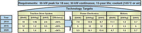
FIGURE 3-5 Hybrid vehicle traction drive performance targets. SOURCE: Rogers (2009).
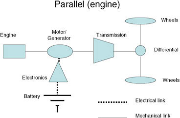
FIGURE 3-6 Schematic of parallel drive configuration for a hybrid vehicle (similar in concept to the Honda Insight Mercedes S series).
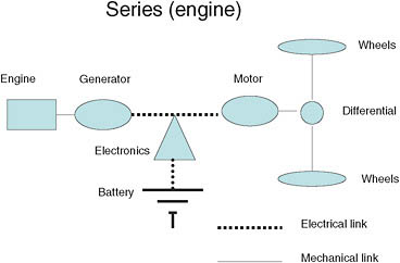
FIGURE 3-7 Schematic of series drive configuration for a plug-in hybrid electric vehicle (similar to the GM Volt).
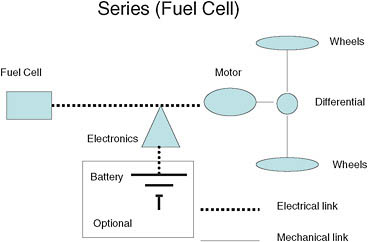
FIGURE 3-8 Schematic of series drive configuration, typical fuel cell vehicle configurations.
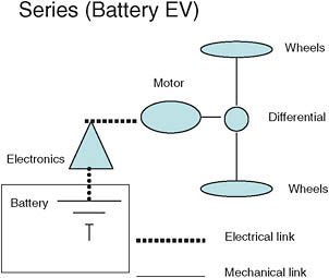
FIGURE 3-9 Schematic of series drive configuration, battery electric vehicle (EV) (similar to the Nissan Leaf and others).
electric motors. Although dc brush motors can be used, this discussion is limited to alternating current (ac) motors (permanent magnet brushless or induction motors) because of their superior performance. Power electronics convert the dc from the source into an ac of variable voltage and variable frequency needed by the motors. It should be noted that these drives have been used for a variety of applications from steel mills to locomotives to appliances, and a great deal of development has taken place. The use of electric propulsion places increased emphasis on
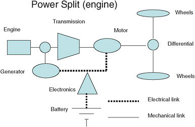
FIGURE 3-10 Schematic of typical power-split hybrid or plug-in hybrid electric vehicle power-train configuration (such as Prius, Escape, and others).
(1) efficiency, to maximize electric range; (2) volume, so that the system can be packaged without reducing space for passengers and cargo; and, of course, (3) cost. Compact and efficient motors and power electronics are essential to all four types of vehicles that the Partnership is working on, namely, HFCVs, HEVs, PHEVs, and BEVs. The present discussion focuses on a review of the traction drive technology status and development efforts to optimize its components for vehicle propulsion, dealing separately with power electronics, electrical machines, and electrical systems.
Power Electronics
The power electronics are composed of a set of semiconductor switches arranged in a block called an inverter, as it converts the dc to ac. Several topologies exist based on control strategies and on whether the frequency conversion is done by the same switches as those for the voltage control. These topologies have been thoroughly investigated over the past 50 years, and basically the selection depends on optimizing the operation. Simply stated, the objectives in the Partnership are to reduce the losses, size, and cost.
Inverter Topology. The inverter changes a dc voltage that varies over narrow limits depending on power to an ac voltage of variable amplitude and frequency depending on motor speed and load; thus the two functions can be performed in two stages (making variable “chopped” dc voltage and then variable frequency) called modulator and inverter or in a single stage called a modulating inverter. It appears
that the program has focused exclusively on the modulating inverter topology and may be missing the advantages of separating the two functions.
Separately, efforts are underway by a Delphi-led team16 to develop a scalable inverter that is capable of being easily sized for a particular application. This approach would dramatically accelerate component and system development time and reduce development costs for all four system types.
Device Cooling. Doped silicon (Si) devices are universally used, and the junction temperature needs to be kept below 125°C. Due to its high band gap and operating temperatures that exceed 250°C, silicon carbide (SiC) offers power inverter efficiencies over silicon. The limitation currently is cost. As noted below, the program is investigating SiC diodes in combination with silicon substrates, and this work needs to continue in spite of today’s higher costs. Recently Denso has exhibited SiC-based “power devices.”17
Switching Speed. The faster the operation the greater the efficiency. Again, devices other than doped silicon, such as the SiC discussed above, have the advantage, and development work should continue.
Components. As stated above for power devices, cooling at higher temperature over ambient is more effective. Power electronics also require capacitors and solders, and in some cases their temperature limits the operation of power electronics. As the cooling of the power devices improves, new materials are needed for both capacitors and solders so that the inverter can operate at a higher temperature.
Thrust Areas in Power Electronics
Scalable Inverter. The concept for a scalable inverter is that it can easily be scaled to meet different power levels. The work on a scalable inverter is a contract of $8.2 million ($4.952 million provided by the DOE and $3.258 million by the contractor) that runs from October 2007 through March 2011 (Taylor, 2009).
SiC Devices. As mentioned in the preceding discussion, SiC devices are better than devices based on doped silicon, because they operate at higher temperatures and have faster switching times. Potentially they lead to smaller and more efficient power electronics. The Partnership is investigating a new process for making SiC
|
16 |
Members and their responsibilities are as follows: Dow Corning/GeneSiC: SiC-on-Si power semiconductor devices; GE: film capacitors; Argonne National Laboratory (ANL): film-on-foil capacitors; Oak Ridge National Laboratory (ORNL): system modeling and simulation, power device characterization, system testing; National Renewable Energy Laboratory (NREL): thermal modeling. |
|
17 |
Detroit Auto Show, Cobo Hall, Detroit, January 2010. |
on silicon substrates. Building these devices on Si is a desirable first step, since expensive SiC wafers are not used, and should be encouraged.
High-Temperature Capacitors. Developing capacitors that can operate at high temperatures could increase the cooling efficiency and thus reduce the size of power electronics. The following activities are being undertaken:
-
ANL: This activity uses metal (copper or nickel) foil coated with thin film Pb-La-Zr-Ti-oxide (PLZT) dielectrics. Demonstrated film-on-foil dielectrics with k (relative static permittivity) greater than 1,300, breakdown field greater than 6 MV/cm. Cost projections are not currently available and would greatly depend on the process steps for producing a capacitor, which are still under investigation. An industry manufacturer has not been identified yet.
-
Pennsylvania State University: This activity uses a flat-panel display glass as a dielectric material and aluminum electrodes. Demonstrated a dielectric constant of 6.2 with a breakdown field of 10 MV/cm. Cost projections are not currently available; laboratory-scale samples are currently expensive, but there is promise in the expanding volume of applications that use flat-panel display glass material. An industry manufacturer has not been identified yet.
-
Sandia National Laboratories (SNL): This activity uses a high-temperature polymer. The measured dielectric constant is 4.6-4.9 with a breakdown voltage of 1.5 MV/cm. The cost of the dielectric material is low (close to that for polypropylene) for laboratory-scale quantities, and the committee expects that it would be even less expensive for large-quantity production. SNL is currently working with Electronic Concepts, Inc., to produce films at a larger scale.
Packaging and Integration. There are activities ongoing on packaging and integration that include the following:
-
Delphi has worked with preferred suppliers to deliver improved silicon integrated gate bipolar transistors and diodes for Delphi’s novel packaging solution.
-
Delphi and ORNL have investigated many thermal management concepts that have been evaluated and analyzed; several invention records have been written for submission and patent applications.
Silicon-on-Insulator Gate Drivers. The silicon-on-insulator (SOI) project is producing a gate driver circuit to function at temperatures of 200°C (the project is ongoing at ORNL, and hardware exists). It does not focus on any power devices—that is, switches or diodes. The committee believes that sufficient fund-
ing currently exists in SiC and gallium nitride (GaN) development elsewhere. It should be noted that the cost is two to four times that of silicon. However, realizing the need for high-temperature drivers to accompany the emergence of high-temperature power devices, this project is an enabler for the higher-temperature operation of inverters and converters. It should be noted that Honda has teamed with Rohm and Haas to develop inverters using SiC devices because of the increase in efficiency as well as the reduction in size because of easier cooling that can be attained in inverter applications. Vehicle implementation is pending safety and cost analysis.18
Progress seems to be as follows:
-
The SOI gate driver was packaged for high-temperature application using solders. No issues have been found in performance testing of the gate driver at temperature.
-
Telefunken has been identified as the fabrication shop. (Telefunken bought Atmel.)
Electrical Machines
In all of the electric drive vehicles, HEVs, PHEVs, BEVs, and HFCVs, an electric motor provides the traction to the wheels, but in some configurations an electrical generator is also needed (see Figures 3-6, 3-7, and 3-10). Primary areas for development are similar to those for power electronics: to reduce size, losses, and cost. The machines are basically of two types and have the following advantages and disadvantages:
-
Permanent magnet brushless motors. These motors became feasible with the invention of high-energy magnets in the 1980s and currently are used in all electric and hybrid vehicles in production (the only exception being the Tesla Roadster). They have high efficiency, which is critical for vehicles, but the magnets are costly, and they require more complex inverters, as operation in what is known as field weakening mode is limited. To overcome some of these limitations, a configuration known as interior permanent magnet (IPM) designs has evolved. IPMs are used both as motors and generators. The presence of permanent magnets may result in a catastrophic failure if, during driving, there is a short circuit of the winding or a failure of insulation. Since the machine is connected to the wheels, it will continue generating voltage, which will result in an abrupt increase in braking torque as well as possible fire, because much energy is continuously dumped into the short circuit.
-
Induction motors. These motors are the workhorses in almost all industrial applications. Although less efficient than motors currently used in
|
18 |
See, for example, <http://japancorp.net/Article.Asp?Art_ID=19769>. |
-
vehicles, they cost less and offer field weakening over a wider speed range. Some original equipment manufacturers (OEMs) have talked about revisiting the choice of motors, and this may be possible if battery costs come down and the premium on efficiency becomes less important than motor costs. Although induction motors are usually used as motors, they can also function as generators. This is obviously important because capturing energy dissipated in the brakes through regenerative braking is essential for the efficient use of the prime-mover energy.
Onboard battery charging during regenerative braking affects the efficiency and cost of the motor. As new battery and motor materials are developed, use of the Powertrain Systems Analysis Toolkit (PSAT), developed at the Argonne National Laboratory under DOE sponsorship, may help quantify material cost and performance trade-offs between motor efficiencies and battery-charging requirements.
Soft Magnetic Materials. The objective in designing new magnetic materials is to reduce two sources of loss, known as (1) hysteresis and (2) eddy current. Conventionally this is accomplished by using thin laminations of steel that contains silicon. The punching and assembly of laminations is expensive, and for years the “holy grail” of soft magnetic materials has been to discover a new material that has both high electrical resistivity and high permeability at the flux density levels needed. As discussed below, the FreedomCAR and Fuel Partnership gave a contract to investigate such materials to General Electric, but it appears that the program was discontinued. Developments in this area, such as the soft magnetic material that Toyota uses in the boost converter in its power electronics, should be monitored (Nozawa et al., 2009).
Cooling. Both liquid and air cooling are conventionally used in vehicles. In the case of hybrid electric vehicles, both oil and engine coolants are available.
Improved Windings. Minimization of the length of winding end turns that does not contribute to output is often used to improve efficiency. Furthermore, an illustration of the lengths to which General Motors and Honda have gone to reduce losses is the fact that they have rectangular conductors, which allow better fill of the slots and thus reduce resistance and improve efficiency.
Thrust Areas for Electrical Machines
A High-Performance Interior Permanent Magnet Machine for Hybrid Vehicles. GE Global Research is the lead organization for a team19 developing an IPM machine for hybrid vehicles. This effort is a contract of $5.8 million ($3.629 million
provided by the DOE and $2.171 million provided by contractors) that runs from October 2007 through June 2011.
The objective is to build a better permanent magnet motor that is designed to provide 30 kW continuous (55 kW peak) power with a top speed of 14,000 revolutions per minute (rpm), a constant power speed range of 5:1, and an efficiency greater than 95 percent at 20 percent torque (El-Rafaie and Johnson, 2009). Other key objectives are for scalable motors to meet the very tough performance specifications and the use of novel soft magnetic material with a tripling of resistivity enhancement. This is desirable because it improves efficiency. This program is half completed but has the following accomplishments:
-
Design of a 30 kW continuous (55 kW peak) motor with a top speed of 14,000 rpm, a constant power speed range of 5:1, and an efficiency greater than 95 percent at 20 percent torque. The latest data show the following accomplishments:
-
Motor design. Two rotor and two stator concepts were developed and analyzed in detail. The machine was ready for testing by the end of March 2009.
-
Low-loss soft magnetic materials. Bulk amorphous alloy composition was identified and kilogram-scale production was accomplished by gas atomization. A novel microstructure was developed to enhance resistivity and magnetic properties. A composite soft magnetic material with a doubling of resistivity enhancement was demonstrated. However, the results showed that the material had too low a flux density and was prohibitively more expensive (four times the cost of silicon steel).20
-
Low-loss permanent magnet materials. Hydrogen-based route for processing the high-energy-density magnet materials used in electrical machines. The project has demonstrated a novel composite microstructure to minimize eddy current losses. A permanent magnet microstructure with three to four times resistivity enhancement was demonstrated. This seems very promising, but the committee’s information is as of May 2009. Additional information available January 2010 indicated the following:
-
Soft magnetic materials: Some of the work was concluded as not being promising. However, one of the industry awards, General Electric, is continuing the work in the hope of a breakthrough. Clearly, if successful, this would revolutionize the electric motor industry.
-
Permanent magnets: The emphasis will be more on molded high-strength magnets. Although these have lower performance than
-
-
-
-
sintered magnets, they are much easier to manufacture into the complex shapes needed for brushless dc motors.
-
Electrical Systems
Conventional vehicles have a large number of electrical systems to control emissions, passenger comfort, and safety that are not discussed here. The focus is on the two subsystems—battery chargers and system controllers—used in hybrid, electric, or fuel cell vehicles.
Battery Chargers. Current HEVs use NiMH or PbA batteries that place minimal requirements on the charger. Battery resistance and temperature can be used to derive a reasonable approximation of the SOC during battery operation. This will change with Li-ion, the likely battery of choice in the future. There are several chemistries in use for Li-ion batteries, and they all have the potential of destructive and hazardous “thermal” events if care is not taken during charging and discharging. Such an event resulted in the recall of millions of laptop computer batteries made by Sony in the 1990s. Even though this recall was attributed to a manufacturing defect, the charging voltage of each cell for current chemistries must be controlled to within a few tens of millivolts per cell, and it is expected that the charging voltage of each cell needs to be monitored and that circuits need to be provided to maintain the voltage within safe limits.
There appears to be relatively little work in the Partnership on battery charging. Although it may be argued that this is postcompetitive activity, in the committee’s view some work needs to be done to ensure safety and to explore rapid charging. The high voltages used in HEVs require many more Li-ion battery cells in series than is typical in smaller electronic equipment for which chargers are commonly used today. In regard to safety, the number of HEVs on the road is not yet sufficient to evaluate statistically the safety of high-voltage HEV battery packs. Moreover, a reduction in the number of cells in an Li-ion battery pack will likely be required in order to meet the target battery cost. One way that this can be achieved is to increase the cell size and decrease or eliminate the number of cells in parallel. However, this approach will affect safety because heat transfer, end-of-charge control, and cell balancing are all more difficult in larger cells. More work will be required to assess the safety of battery chargers as a function of the cell sizes and battery pack configurations, as well as any changes in the battery chemistry that are ongoing in Li-ion battery development. A three-dimensional performance model of large-format cells may be useful in predicting the over-voltage and temperature variations in large-format cells during high-rate charging (see, e.g., the NREL model, Kim and Smith [2008]). In regard to rapid charging, this strategy is seen as potentially essential to the broad penetration of BEVs. Systematic study of rapid charging implications for battery life and safety of various Li-ion batteries could prove to be of high value in moving forward.
System Controllers. System controllers need to control the vehicle in response to the driver’s commands. During acceleration an HEV or BEV should have the “feel” of conventional vehicles, although the high torque produced by electric motors, especially at low speed, is probably an advantage. The controller will also need to control regenerative braking to minimize energy drain from the battery or the fuel cell. It should be pointed out that there is little activity in this area of electrical systems in the Partnership, and this is justified in the committee’s view because technology development is in the “competitive areas” of each OEM. The exception to this is a remarkable drive for the compressor expander motor (CEM) of the air supply system for a fuel cell balance of plant as discussed below.21
Compressor Expander Motor for Fuel Cell Vehicles. The CEM project incorporates a high-speed drive (165,000 rpm) with a fairly low projected cost. At a production of 500,000 annual units, the projected cost of the CEM is $293 and the cost of the controller is $303, with a total cost of $705 including assembly ($31) and a markup (15 percent for the CEM and 10 percent for the controller). Information provided subsequent to the meeting shows that this is a system similar to a 100,000 rpm demonstration unit from Honeywell. Such speeds are certainly unusual in automotive electric motor applications but, if successful, are very useful for keeping the weight and volume of the system down. The motor is a permanent magnet brushless motor with 2 poles, thus requiring switching devices operating at a minimum of 2,750 hertz (Hz). This is based on a design at Honeywell for motors in excess of 200,000 rpm (requiring a minimum switching frequency of 3,333 Hz). Although the details of the motor and motor controller are proprietary, the motor controller and motor are reported to have efficiencies of greater than 90 percent and greater than 93 percent, respectively, for a combined efficiency near 85 percent, which is truly remarkable at such speeds and frequencies. The motor stator and motor controller can be liquid- or air-cooled, but the rotor must be air-cooled. The cost does not include the entire cooling system cost, as the cooling system is shared with the vehicle’s traction drive motor. Because of the critical importance of the CEM for HFCVs, the committee encourages continued support for further testing of this integrated subsystem—in particular with respect to noise and vibration as well as durability at conditions that can be expected in the automotive environment. In the opinion of the committee, this is the kind of stretch technology that is needed to reduce component size and material cost.
Recommendations
Recommendation 3-19. The Partnership should continue to focus on activities to reduce the cost, size, and losses in the power electronics and electrical machines.
Recommendation 3-20. The Partnership should conduct a project to evaluate the effect of battery charging on lithium-ion battery packs as a function of the cell chemistries, cell geometries, and configurations in the pack; battery string voltages; and numbers of parallel strings. A standardized method for these evaluations should be developed to ensure the safety of battery packs during vehicle operation as well as during plug-in charging.
Recommendation 3-21. The Partnership should consider conducting a project to investigate induction motors as replacements for the permanent magnet motors now almost universally used for electric propulsion.
STRUCTURAL MATERIALS
The challenge to the materials technical team is to generate a cost-neutral 50 percent vehicle weight reduction. The 50 percent weight reduction is critical to reaching FreedomCAR goals for fuel consumption and emissions. However, the target of no cost penalty for such a large weight reduction was unrealistic when set, and it remains unrealistic. A similar conclusion was stated in the Phase 2 report (NRC, 2008). What is missing at this juncture is a projection of what the cost penalty will likely be. For example, Berger et al. (2009) considered an aggressive weight-reduction program that yielded a 37 percent reduction (230 lb) in the Golf V body-in-white (BIW) which generated a 112 percent ($1,088) increase in cost. In other words, each 1 percent weight reduction in the BIW yielded a 3 percent increase in cost. Computer simulation was used to ensure that stiffness and crashworthiness requirements were met. An additional 50 percent weight savings of 115 lbs may be possible from downsizing brakes, suspension, engine, power train, and wheels and tires. But the associated cost savings are unlikely to make up the needed $1,000 plus. A full vehicle study is needed by FreedomCAR to assess the estimated overall cost penalty. Based on the above study, the outcome may be a penalty well over $500. What is also missing at this juncture is how the cost penalty changes as a function of the percent of weight reduction, assuming that the most effective mix of materials is used at each step in the weight-reduction process. This information will be needed in case the overall system-level targets for FreedomCAR need to be reset.
Weight Reduction Calculus
The impact of weight reduction on fuel consumption is well understood, and automotive OEMs have worked for many years to develop effective vehicle weight-reduction technologies. Consider, for example, a vehicle that is driven 12,000 miles per year having an average fuel economy of 25 mpg (0.04 gal/mi). The vehicle is then redesigned to achieve a 10 percent weight reduction using lightweight materials and/or better structural utilization. Fuel consumption would then be expected to be reduced by at least 6 percent, resulting in a new fuel economy of at least 26.6 mpg. The total of 480 gal used annually at 25 mpg would be reduced to 451 gal. For gas priced at $2.50/gal, the annual fuel costs of $1,270 at 25 mpg would be reduced by $72.50 due to the weight reduction. When computed over 6 years using an 8 percent discount rate for future savings, the resulting net present value (NPV) for the redesign is $335. Thus, there would be an NPV incentive of more than $100 to the buyer if the one-time, up-front added material costs were under $200.
This is an example of the value of developing weight-reducing technologies not only to the entire industry, but to the nation as well. For example, if each passenger car in the United States was reduced in weight by 10 percent, the expected annual savings in fuel would be more than 4.5 billion gallons, based on the 2006 vehicle fuel usage statistics. There would be large additional savings in societal value resulting from reduced pollution and reduced dependence on foreign oil that are not reflected in consumer (commercial) value of $289 computed above.
Also, there does not need to be a trade-off between increased fuel economy and safety. Mass reduction is an important means of improving fuel economy. But mass is not the same as size, and with efficient designs, low-mass cars can be made safe by improving crash-management design and reducing the frequency of accidents through improved accident-avoidance systems in vehicles and on highways.
Mass Decompounding
A weight-reduction process known as mass decompounding can be utilized when brakes, suspension, and power train can be redesigned to gain secondary weight savings as a result of the primary weight savings made in the structure through the use of lightweight materials. A lighter vehicle can perform equally well with smaller brakes, a less hefty suspension, and a smaller engine.
During the past year, the materials technical team arrived at a useful rule of thumb in which 1.0 to 1.5 lb of secondary weight savings should be achievable for each 1 lb of primary weight saved, provided that the entire vehicle can be redesigned to take advantage of the savings. The relationship for the amount of secondary weight savings was determined from an analysis of teardown data from two vehicle databases by the materials technical team.
If it is assumed that each 1.0 lb of lightweight material generates 1.25 lb of secondary weight savings on average, then a current vehicle weighing
3,000 lb will require 667 lb of primary weight savings to meet the 50 percent weight reduction goal of 1,500 lb.
Magnesium Power-Train Components
The targets for the project on magnesium power-train components have been to replace aluminum components with magnesium for a minimum weight savings of 15 percent and a cost penalty of less than $2.00 for each pound saved. This project was completed in September 2009. The mass reduction achieved was 29 percent for the magnesium components and 7.8 percent for the engine subsystem, which exceeded the weight-savings goal. The cost penalty was found to be $3/lb at current magnesium prices. Although over the cost target, the outcome was judged as demonstrating that magnesium was both technically feasible and potentially cost-effective in these applications.
Polyolefin Feedstock
Cost has been a limiting factor in the use of commercial carbon-fiber-reinforced composites in the design of automotive structures and body panels. Importantly, the materials technical team has shown that major cost savings appear possible through the use of polyolefin for the feedstock in making carbon fibers.22 As with all lightweight materials applications, the trade-offs between cost and weight will need to be reevaluated as the price of oil changes. If the price of oil doubles, the cost of polyolefin will increase significantly, since polyolefin comes mostly from oil or perhaps natural gas. If the price of oil doubles, for example, the incentive to use carbon fibers in cars will increase because of the reduction in weight, but the cost of the polyolefin and therefore the carbon fiber will also increase. The DOE needs to understand the trade-offs there.
Recycling End-of-Life Vehicles
New materials present challenges to recycling. ANL is developing a one-fifth scale pilot operation to assess how to recover residual metals and polymers from the residue from shredders. A second pilot operation is to begin in the first quarter of 2010 to evaluate the recycling of polyurethane foams by converting them to polyols. The FreedomCAR and Fuel Partnership also needs to consider how to recycle carbon-fiber-reinforced composites including carbon-fiber hydrogen tanks.
Response to the Phase 2 Recommendations
A recommendation from the Phase 2 report (NRC, 2008, p. 9) is as follows:
Recommendation. The materials research funding should largely be redistributed to areas of higher potential payoff, such as high-energy batteries, fuel cells, hydrogen storage, and projects associated with infrastructure issues. However, materials research for projects that show a high potential for enabling near-term, low-cost mass reduction should continue to be funded.
The response of the Partnership was as follows:23
-
Strategic lightweighting is an important enabler for reducing fuel consumption.
-
We recommend that lightweighting materials research funding not be redistributed to support other technology areas.
-
We agree that materials research for projects that show a high potential for enabling near-term, low-cost mass reduction should continue to be funded.
Recommendations
The materials needed to make the required weight reductions—high-strength steels, aluminum, titanium, magnesium, and fiber-reinforced composites—are available. The key issue is not improving their performance but getting the weight reductions needed at an acceptable cost. The structural materials efforts and budget should reflect this reality. The resources required in the future may be less or more if major pilot programs are needed. Systems analysis is an approach that can highlight where critical cost reductions are needed. The polyolefin feedstock is a good example of what can be achieved. The high cost of aerospace-quality carbon fiber is a major impediment to achieving cost-effective compressed hydrogen storage.
Recommendation 3-22. The materials technical team should develop a systems-analysis methodology to determine the currently most cost-effective way for achieving a 50 percent weight reduction for hybrid and fuel cell vehicles. The materials team needs to evaluate how the cost penalty changes as a function of the percent weight reduction, assuming that the most effective mix of materials is used at each step in the weight-reduction process. The analysis should be updated on a regular basis as the cost structures change as a result of process research breakthroughs and commercial developments.
Recommendation 3-23. The magnesium castings study is completed, and no further technical effort is anticipated by the Partnership as recommended in the Phase 2 report. However, magnesium castings should be considered in completing the cost reduction recommendation listed above.
Recommendation 3-24. Methods for the recycling of carbon-reinforced composites need to be developed.
REFERENCES
Anderson, B., and I. Wade, 2001. Metal resource onstraints for electric vehicle batteries, Transportation Research Record D 6: 297-324.
ANL (Argonne National Laboratory). 2009. Technical Assessment of Cryo-Compressed Hydrogen Storage Tank Systems for Automotive Applications. Report ANL/09-33, by R. K. Ahluwalia, T. Q. Hua, J.-K. Peng, Argonne National Laboratory, Argonne, Illinois; S. Lasher, K. McKenney, and J. Sinha, TIAX LLC, Cambridge, Massachusetts. Argonne, Ill.: ANL. Federal Grant Number DE-ACO2-06CH11357. Available on the Web at <http://www1.eere.energy.gov/hydrogenandfuelcells/pdfs/cyro_compressed_auto.pdf>.
Bandivadekar, A., K. Bodek, L. Cheah, C. Evans, T. Groode, J. Heywood, E. Kasseris, M. Kromer, and M. Weiss. 2008. On the Road in 2035: Reducing Transportation’s Petroleum Consumption and GHG Emissions. Report No. LFEE 2008-05 RP (July). Cambridge, Massachusetts: MIT Laboratory for Energy and the Environment.
Berger, Lutz et al., 2009. “Super LIGHT CAR—the Multi-Material Car Body.” Presented at the 7th European LS-DYNA Conference. Available on the Web at <http://www.dynalook.com/european-conf-2009/B-V-03.pdf>.
Department of Energy (DOE). 2009a. Hydrogen, Fuel Cells and Infrastructure: Multi-Year Research, Development and Demonstration Plan. DOE/GO-102003-1741. Washington, D.C.: U.S. Department of Energy, Energy Efficiency and Renewable Energy (original edition, 2004; revised April 2009). Available on the Web at <http://www.eere.energy.gov/hydrogenandfuelcells/mypp/>.
DOE. 2009b. Hydrogen Program. “Announcement for H Prize.” Available on the Web at <http://www.hydrogen.energy.gov/news_h-prize_administrator.html>.
DOE. 2009c. Actions and Evidence Report, April 2. Submitted to the National Research Council (NRC) Committee on Review of the FreedomCAR and Fuel Research Program, Phase 3, documenting responses by DOE to recommendations in the Phase 2 report [see NRC, 2008].
DOE. 2009d. 2009 Annual Progress Report, DOE Hydrogen Program. DOE/GO-102009-2950 (November). Washington, D.C.: Office of Energy Efficiency and Renewable Energy. Available on the Web at <http://hydrogendoedev.nrel.gov/pdfs/progress09/2009_doe_hydrogen_program_annual_progress_report_cover.pdf>.
El-Rafaie, A., and F. Johnson. 2009. “Scalable, Low-Cost, High Performance IPM Motor for Hybrid Vehicles.” Presentation at the DOE Annual Merit Review, May 22. Available on the Web at <http://www1.eere.energy.gov/vehiclesandfuels/pdfs/merit_review_2009/advanced_power_electronics/ape_08_elrefaie.pdf>.
Howell, D. 2009. Annual Progress Report for 2008, Energy Storage Research and Development (January). Washington, D.C.: U.S. Department of Energy, Office of Energy Efficiency and Renewable Energy. Available on the Web at <http://www1.eere.energy.gov/vehiclesandfuels/pdfs/program/2008_energy_storage.pdf>.
James, B., and J. Kalinoski. 2009. “Mass-Production Cost Estimation of Automotive Fuel Cell Systems.” Presentation at DOE 2009 Annual Merit Review, May 21, Arlington, Virginia. Available on the Web at <http://www.hydrogen.energy.gov/pdfs/review09/fc_30_james.pdf>.
Kim, G., and K. Smith. 2008. “Three-Dimensional Lithium-Ion Battery Model.” 4th International Symposium on Large Lithium Ion Battery Technology and Application, Tampa, Florida, May 12-14. NREL/PR-540-43166. Available on the Web at <http://www.nrel.gov/vehiclesandfuels/energystorage/pdfs/43166.pdf>.
Nozawa, N., T. Maekawa, S. Nozawa, and K. Asakura. 2009. Development of Power Control Unit for Compact-Class Vehicle, SAE 2009-01-1310, April.
NRC (National Research Council). 2008. Review of the Research Program of the FreedomCAR and Fuel Partnership, Second Report. Washington, D.C.: The National Academies Press.
Rogers, S. 2009. “Advanced Power Electronics and Electric Machines.” Presentation at the DOE Annual Merit Review, May 21. Available on the Web at <http://www1.eere.energy.gov/vehiclesandfuels/pdfs/merit_review_2009/advanced_power_electronics/ape_0_rogers.pdf- 916.8KB>
Satyapal, S. 2009. “Hydrogen Program Overview.” DOE Annual Merit Review and Peer Evaluation Meeting, May 18. Available on the Web at <http://www.hydrogen.energy.gov/pdfs/review09/program_overview_2009_amr.pdf>.
Sinha, J., S. Lasher, and Y. Yang. 2009. “Direct Hydrogen PEMFC Manufacturing Cost Estimation for Automotive Applications.” Presentation at the DOE 2009 Annual Merit Review, May 21, Arlington, Virginia. Available on the Web at <http://www.hydrogen.energy.gov/pdfs/review09/fc_31_sinha.pdf>.
Taylor, J. 2009. “Development, Test and Demonstration of a Cost-Effective, Compact, Light-Weight, and Scalable High Temperature Inverter for HEVs, PHEVs, and FCVs.” DOE Annual Merit Review and Peer Evaluation Meeting, May 21. Available on the Web at <http://www1.eere.energy.gov/vehiclesandfuels/pdfs/merit_review_2009/advanced_power_electronics/ape_07_taylor.pdf>.
TIAX. 2009. Technical Assessment of Compressed Hydrogen Storage Tank Systems for Automotive Applications. Report to United States Department of Energy, Office of Energy Efficiency and Renewable Energy; Hydrogen, Fuel Cells and Infrastructure Technologies Program; Part 1 (Volume 1), December 10. Federal Grant Number: DE-FC36-04GO14283, Stephen Lasher, Kurtis McKenney, and Jayanti Sinha, TIAX LLC, Cambridge, Massachusetts, Reference: D0268; Rajesh Ahluwalia, Thanh Hua, and J-K Peng, Argonne National Laboratory.
Weiss, M. A., J.B. Heywood, E.M. Drake, A. Schafer, and F.F. AuYeung. 2000. On the Road in 2020: A Life-Cycle Analysis of New Automobile Technologies. Cambridge, Massachusetts: MIT Laboratory for Energy and the Environment.
Xu, J., H.R. Thomas, Rob W. Francis, Ken R. Lum, Jingwei Wang, Bo Liang. 2008. A review of processes and technologies for the recycling of lithium-ion secondary batteries, Journal of Power Sources 177 (2008) 512-527.
ANNEX
TABLE 3A-1 Technical System Targets: Onboard Hydrogen Storage for Light-Duty Vehicles
|
Storage Parameter |
Units |
2010 |
2015 |
Ultimate |
|
System Gravimetric Capacity |
|
|
|
|
|
Usable, specific-energy from H2 |
kWh/kg |
1.5 |
1.8 |
2.5 |
|
(net useful energy/max system mass)a |
(kg H2/kg system) |
(0.045) |
(0.055) |
(0.075) |
|
System Volumetric Capacity |
|
|
|
|
|
Usable energy density from H2 |
kWh/L |
0.9 |
1.3 |
2.3 |
|
(net useful energy / max system volume) |
(kg H2/L system) |
(0.028) |
(0.040) |
(0.070) |
|
Storage System Costb |
$/kWh net |
4 |
2 |
TBD |
|
(and fuel cost)c |
($/kg H2) |
(133) |
(67) |
|
|
|
$/gge at pump |
2-3 |
2-3 |
2-3 |
|
Durability/Operability |
|
|
|
|
|
Operating ambient temperatured |
°C |
−30/50 (sun) |
−40/60 (sun) |
−40/60 (sun) |
|
Min/max delivery temperature |
°C |
−40/85 |
−40/85 |
−40/85 |
|
Cycle life (1/4 tank to full)e |
Cycles |
1000 |
1500 |
1500 |
|
Cycle life variationf |
% of mean (min) at % confidence |
90/90 |
99/90 |
99/90 |
|
Min delivery pressure from storage system; FC = fuel cell, ICE = internal combustion engine |
Atm (abs) |
4FC/35 ICE |
3FC/35 ICE |
3FC/35 ICE |
|
Max delivery pressure from storage systemg |
Atm (abs) |
100 |
100 |
100 |
|
Storage Parameter |
Units |
2010 |
2015 |
Ultimate |
|
Charging/Discharging Rates |
|
|
|
|
|
System fill time (for 5 kg H2) |
Min (kg H2/min) |
4.2 min (1.2 kg/min) |
3.3 min (1.5 kg/min) |
2.5 min (2.0 kg/min) |
|
Minimum full flow rate |
(g/s)/kW |
0.02 |
0.02 |
0.02 |
|
Start time to full flow (−20 °C)h |
s |
5 |
5 |
5 |
|
Start time to full flow (20 °C)h |
s |
15 |
15 |
15 |
|
Transient response 10%-90% and 90%-0%i |
s |
0.75 |
0.75 |
0.75 |
|
Fuel Purity (H2 from storage)j |
% H2 |
99.99 (dry basis) |
99.99 (dry basis) |
99.99 (dry basis) |
|
Environmental Health and Safety |
|
|
|
|
|
Permeation and leakagek |
Scc/h |
Meets or exceeds applicable standards |
Meets or exceeds applicable standards |
Meets or exceeds applicable standards |
|
Toxicity |
— |
|||
|
Safety |
— |
|||
|
Loss of usable H2l |
(g/h)/kg H2 stored |
0.1 |
0.05 |
0.05 |
|
a Generally the “full” mass (including hydrogen) is used, for systems that gain weight, the highest mass during discharge is used. b 2003 US$; total cost includes any component replacement if needed over 15 years or 150,000 mile life. The storage system costs are currently under review and will be changed at a future date. c 2005 US$; includes off-board costs such as liquefaction, compression, regeneration, etc; based on H2 production cost of $2 to $3/gasoline gallon equivalent untaxed, independent of production pathway. d Stated ambient temperature plus full solar load. No allowable performance degradation from −20C to 40C. Allowable degradation outside these limits is TBD. e Equivalent to 100,000; 200,000; and 300,000 miles respectively (current gasoline tank spec). f All targets must be achieved at end of life. g For delivery the storage system, in the near term, the forecourt should be capable of delivering 10,000 psi (700 bar or ca. 70 MPa) compressed hydrogen, liquid hydrogen, or chilled hydrogen (35 to 77 K) and up to 5,000 psi (350 bar or ca. 35 MPa). In the long term, it is anticipated that delivery pressures will be reduced to between 50 and 150 atm for solid state storage systems, based on today’s knowledge of sodium alanates. h Flow must initiate within 25% of target time. i At operating temperature. |
||||
|
j The storage system will not provide any purification, but will receive incoming hydrogen at the purity levels required for the fuel cell. For fuel cell systems, purity meets SAE J2719, Information Report on the Development of a Hydrogen Quality Guideline in Fuel Cell Vehicles. Examples include: total nonparticulates, 100 ppm; H2O, 5 ppm; total hydrocarbons (C1 basis), 2 ppm; O2, 5 ppm; He, N2, Ar combined, 100 ppm; CO2, 1 ppm; CO, 0.2 ppm; total S, 0.004 ppm; formaldehyde (HCHO), 0.01 ppm; formic acid (HCOOH), 0.2 ppm; NH3, 0.1 ppm; total halogenates, 0.05 ppm; maximum particle size, <10 μm; particulate concentration, <1 μg/L H2. These are subject to change. See Appendix C on Hydrogen Quality, to be updated as fuel purity analyses progress. Note that some storage technologies may produce contaminants for which effects are unknown; these will be addressed as more information becomes available. k Total hydrogen lost into the environment as H2; relates to hydrogen accumulation in enclosed spaces. Storage system must comply with CSA/NGV2 standards for vehicular tanks. This includes any coating or enclosure that incorporates the envelope of the storage system. l Total hydrogen lost from the storage system, including leaked or vented hydrogen; relates to loss of range. SOURCE: DOE (2009a). |


