
5
Geodetic Reference Frames and Co-Location Requirements
Modern geodetic methods have enabled the positions of geodetic stations to be determined within a well-defined frame of reference; as a result, the long-term movements of the Earth’s surface can now be monitored at a level of approximately one millimeter per year. Dense networks of GNSS/GPS stations are used to map the strain in the Earth’s crust at plate boundaries and to “observe” plate tectonics as they happen. The Earth’s geometrical and gravitational shapes and its orientation in space are being monitored to determine the redistribution of fluids on or near the Earth’s surface, including the ocean and atmosphere, the cryosphere, and the terrestrial hydrosphere. All of these scientific applications depend on a truly global reference system that only geodesy can provide. In addition, navigation systems, such as those based on GPS, are typically referenced to a specific reference frame. This chapter describes the importance of the International Terrestrial Reference Frame (ITRF) and its current level of accuracy, limiting factors, and requirements for future improvements. It also discusses the relationship between the global reference frame (represented by the ITRF) and regional reference frames.
The ITRF is the primary global spatial reference system in existence today, although other regional reference frames also have been developed. The ITRF is created and maintained, or “realized,” by using geodetic observations to determine the positions and velocities of physical reference points on the Earth’s surface, and matching them as closely as possible to the mathematical and physical properties of an idealized, or theoretical, frame. The reference points for the ITRF may consist of geodetic equipment on the ground, or fixed points within the geodetic instruments themselves.
The main physical and mathematical properties of a reference frame are the origin, the scale, the orientation, and the changes in these parameters over time. The “origin” of a reference frame is the zero point of the three Cartesian axes (i.e., X, Y, and Z), typically the center of mass of the entire Earth system. This point can be determined most accurately from the observations of satellite motion, as satellites naturally orbit about Earth’s center of mass. The “scale” refers to the absolute distance between points in the network. It is a uniform scaling of all coordinates, with the result that a scale error in the reference frame results in a radial (height) error for all stations. Similarly, a scale-rate error results in an error in all vertical rates, a particularly insidious error that can, for example, significantly affect the interpretation of very small changes in sea level rise and in surface deformation
due to tectonic plate dynamics. The “orientation” essentially refers to the definition of the zero point for longitude and latitude. Unlike origin and scale, which are determined directly by the geodetic observations, we are free to choose any point on Earth as zero longitude or zero latitude. We try to maintain consistency with the historical Greenwich meridian for zero longitude and Earth’s equator as zero latitude, which is perpendicular to the Earth’s spin axis, but these directions cannot be fixed due to plate tectonic motion and polar motion. Therefore, by convention the orientation of the ITRF is designed to maintain consistency with previous reference frames and specified by the requirement of no-net or zero-average rotation with respect to horizontal plate motion of the Earth’s surface. This is difficult to realize in practice due to the limited number of sites distributed on the various continental plates, which are all moving above Earth’s mantle and core.
Continuous, long-term geodetic observations are crucial if the ITRF is to account correctly for the complex movements of points on the surface of the Earth, so that we can characterize and model these movements precisely. In the absence of technique-specific systematic errors, and if all geophysical processes are accurately accounted for in the geodetic analysis, the ITRF properties should be stable over time (that is, they should not exhibit any drift or discontinuities over the time-span of the geodetic observations; see Box 5.1). Any deficiencies in the accuracy or continuity of the ITRF will limit the quality of science that it can support.
STABILITY AND ACCURACY OF THE ITRF
The stability and accuracy of the ITRF over long time periods is a primary limiting factor for understanding sea level change, land subsidence, crustal deformation, and ice sheet dynamics. Of these, a quantifying long-term change in sea level imposes the most stringent observation requirements. The ITRF constitutes the foundation connecting observations in space, time, and evolving technology, and provides the framework in which global and regional observations of sea level change can be understood and properly interpreted. A stable ITRF is required if sea level measurements at sub-millimeter accuracy made today are to be meaningfully compared with measurements made a decade from now. The ITRF also can be extended to regional and local studies in order to link multidisciplinary observations and ensure long-term consistency, precision, and accuracy (see Box 5.1). For the ITRF to accurately quantify long-term sea level change, the ITRF must be both accurate and accessible at the 1-millimeter level, with a stability of 0.1 millimeters per year.
Given that existing reference frames have not achieved this level of accuracy and stability, it is not surprising that one of the largest sources of error in the global characterization of long-term sea level variation is uncertainty in the ITRF. For example, a 2-millimeter-per-year error in the relative velocity between the Earth’s mean surface and the Earth system’s center of mass can result in an error as large as 0.4 millimeters per year in the determination of mean global sea level variation using satellite altimetry (see Table 3.1). The effect on measuring local or regional sea level can be even larger. A scale rate error of 0.1 parts per billion per year would cause an apparent sea level change of 0.6 millimeters per year. To put this in context, the mass loss from the Greenland ice sheet is estimated to be on the order of 200 gigatons per year on average over the last few years, corresponding to approximately 0.7 millimeters per year of rise in global mean sea level; Antarctica is losing a similar amount of ice (Velicogna, 2009). Thus, the uncertainty in the observation of sea level change due to errors in the ITRF is currently almost at the same level as the contribution of either ice sheet to sea level rise. Furthermore, there is evidence that the rate at which ice sheets lose mass is increasing by approximately 30 gigatons per year (corresponding to approximately 0.1 millimeters per year increase in sea level rate) (Velicogna, 2009). Improving the ITRF is, therefore, of paramount importance for the study of global sea level rise and its possible acceleration.
|
BOX 5.1 Defining Precision, Accuracy, Stability, and Drift The quality of positioning within a reference frame is described in terms of precision, accuracy, stability, and drift: Precision quantifies the ability to repeat the determination of position within a reference frame (internal precision) and can be measured using various statistical methods on samples of estimated positions. Although precision does not imply accuracy, high precision is a prerequisite for consistently high accuracy and is necessary to resolve changes in position over time. The precision of a reference frame itself (external precision) refers to the variation in the reference frame parameters (origin, orientation, and scale) that arise from statistical variation in the data used to define the frame. Accuracy quantifies how close a position is to the truth. Strictly, it only applies to absolute physical quantities, such as distance between stations, but this report also uses it to mean accuracy of station position within a reference frame (internal accuracy). Precision contributes to accuracy, but accuracy also takes into account systematic biases arising from calibration errors or imperfect observation models. Accuracy can be assessed if there is a superior measurement technique that can be used as a standard, but since geodesy uses the highest-accuracy techniques, accuracy estimation is not straightforward for geodesy. Accuracy estimates for geodesy therefore typically involve an “error budget” analysis of systematic effects. Stability refers to the predictability of the reference frame and station positions. The stability of the reference frame refers to the behavior (linearity and consistency) of its defining parameters, and the ability to predict accurately the future positions of the stations that are used to define the frame. That is, the ITRF parameter should not exhibit any discontinuity over the entire time span of the geodetic observations. Furthermore, the ITRF should remain internally consistent even as it is updated from time to time. The stability of a station refers to the ability to predict its future position within the reference frame. For example, local site stability typically implies that all stations at a specific site do not move relative to each other, and the site does not have non-linear motions relative to the ITRF. The deviation of measured station positions from their predicted positions provides information on geophysical processes that were not predicted. Stations of special geophysical interest (for example, for measuring topographic change in the Las Vegas Valley caused by groundwater effects) are obviously not well suited for defining the reference frame, but it is the stability of the frame that allows scientists to detect the interesting and important geophysical effects on the motions of these stations. Drift refers to relative rotation, translation, and scale between different reference frames, which results in different velocities between stations given in each frame. Drift is a consequence of a lack of stability in one or both of the frames being compared, which in turn may result from systematic error in the measurement techniques, lack of precision in the measurements, or differences in the station motion models. |
GEODETIC TECHNIQUES FOR REALIZING THE ITRF
The geodetic techniques that provide measurements for realizing the ITRF are Very Long Baseline Interferometry (VLBI); Global Navigation Satellite Systems (GNSS)/Global Positioning System (GPS); Satellite Laser Ranging (SLR), and Doppler Orbitography Radiopositioning Integrated by Satellite (DORIS). The ground network for each of these geodetic techniques is illustrated in Figure 5.1. These techniques are organized as scientific services within the International Association of Geodesy (IAG) and are integral components of the Global Geodetic Observing System (GGOS) (Plag, 2005; Plag and Pearlman, 2009), which is the IAG’s participating organization in the international Group on Earth Observations. Each of these observational techniques has unique characteristics, strengths, and weaknesses. VLBI provides the orientation of the ITRF relative to the celestial reference frame (i.e., the ‘distant stars’) and is also one of the two techniques currently used for accurately realizing the scale of the ITRF. SLR is used to locate the center of mass of the Earth
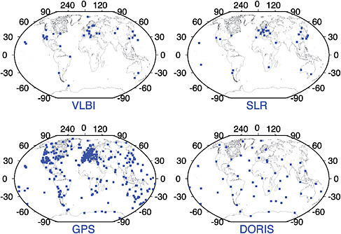
FIGURE 5.1 The network distribution of the four geodetic techniques contributing to the ITRF. Shown are the stations that contributed data during the year 2009. There are thousands of geodetic GPS receivers deployed worldwide, but only a subset of these receivers, coordinated by the International GNSS Service (IGS), are used for the ITRF definition. SOURCE: Courtesy of Zuheir Altamimi, 2010.
system and thereby defines the ITRF origin and contributes to the ITRF scale. GPS contributes the large number of sites that define the ITRF (contributing to its density) and contributes to precise monitoring of polar motion. GPS, DORIS, and SLR are used to position space-orbiting platforms in the ITRF, and GPS is used to position instruments on the Earth’s land and sea surfaces (for example, tide gauges and buoys). Locating instruments for two or more techniques near each other at certain ITRF sites (a practice called “co-location”) enables connectivity between these techniques.
None of the space geodesy techniques alone is capable of providing all the necessary parameters for ITRF definition (origin, scale, and orientation). Although satellite techniques are sensitive to the center of mass of the entire Earth system (a natural ITRF origin and the point around which a satellite orbits), the VLBI technique is not (its ITRF origin is arbitrarily defined through mathematical calculations). The scale is dependent on the modeling of some physical parameters (such as troposphere or ionospheric refraction), and the absolute ITRF orientation (unobservable by any technique) is conventionally defined through specific mathematical constraints, typically to try to realize no-net or zero-average rotation with respect to the bulk of the Earth’s mass. Multi-technique combinations are therefore essential for the ITRF determination.
The most critical ITRF parameters of interest to mean sea level studies in particular, and other investigations in general, are the origin and scale and their long-term stability. For example, any scale bias in the ITRF definition propagates directly to the height component of the stations, and any scale and/or origin bias will directly map to the mean sea level estimation (Beckley et al., 2007). Although SLR currently provides the most accurate realization of the Earth’s long-term center-of-mass (the geo-
center) for the ITRF origin, estimates of the geocenter location (and its variations owing to seasonal mass redistribution on the Earth’s surface, an important geophysical signal in itself) still need to be improved for all the geodetic techniques. Because the ITRF relies on SLR to define its origin and on SLR and VLBI for its scale, the importance of these two techniques for ITRF accuracy and stability over time should not be underestimated. Hence, the problems of scale and origin stability that can particularly affect GNSS/GPS techniques can be overcome by careful alignment to the ITRF, which in turn requires sufficient overlap in networks at co-located sites. Unfortunately, the current SLR and VLBI networks and their co-locations are already poorly distributed and are decreasing over time, posing a threat for the long-term stability of the ITRF. For example, the analysis of the ITRF of 2005 and the pre-2008 analysis showed that the poorly distributed SLR and VLBI networks and scale bias up to 1 part per billion (corresponding to 6 millimeters) and a scale drift up to 0.1 part per billion per year (0.6 millimeters per year). This drift is considerably larger than the science requirement (less than 0.1 millimeters per year) to measure sea level change (see Table 3.1).
Thus, the ITRF is based on information derived from a combination of multiple geodetic techniques. As described in Chapter 4, however, each technique has its own unique targets; VLBI observes quasars, SLR ranges to selected laser geodetic satellites, and GNSS/GPS depends on the navigation satellites. Though this may change in the future, no technique currently contributing to the ITRF has a direct connection to any other technique. Each realizes its own internally consistent set of coordinates, but it is only through local ties at co-located sites that a completely resolved reference frame is realized. As a result, the ITRF quality will suffer from any network degradation over time because it is heavily dependent on the network configuration. The current configuration of co-located sites (in particular, sites with three and four co-located techniques) is far from optimal. The following sections describe the current configuration of co-location sites, including their quality, number, and distribution.
CO-LOCATION SITES
A co-location site is defined by the presence of two or more geodetic instruments occupying simultaneously or subsequently very close locations. These locations must be precisely surveyed in three dimensions, using either classical geodetic methods (usually angles, distances, and leveling measurements between instrument reference points or geodetic markers) or GNSS/GPS (Altamimi, 2005). The national agencies that operate geodetic instruments generally perform least-squares adjustments of local surveys to yield the local ties that connect co-located instrument reference points. Geodetic markers are unambiguous reference points for which geodetic coordinates can be determined. Markers can be either a well-defined physical point anchored in a geodetic monument (such as a pillar or pole) or an instrument reference point (for example, the intersection of axes of an SLR telescope or VLBI antenna, or a GNSS/GPS or DORIS antenna reference point).
Inter-marker distance and accuracy of the local tie are the two main criteria that must be considered for the definition of a co-location site (Altamimi, 2005). Given the need for local tie vectors to be precise at the 1-millimeter level, and considering the increase in atmospheric refraction as a function of increased station separation, the distances between geodetic markers at co-location sites should not exceed 1 kilometer. In addition, repeat surveys of the marker “footprint” are necessary for long-term local tie stability. The current reality, however, is sub-optimal. The poor geographic distribution and insufficient number of co-location sites forces geodesists, for the purpose of the ITRF determination, to consider stations to be co-located even when separated by up to 30 kilometers (for example, the Tidbinbilla/Orroral complex site in Australia). In terms of accuracy, the typical uncertainty of the local ties used for the current ITRF is 2–5 millimeters (sometimes larger than 5 millimeters for the less precise ties). With the increased precision available from geodetic techniques, a precision of 1 millimeter or better should be the goal of all new local tie surveys.
Current Status and Future Requirements of Co-location Sites
At the writing of this report (2010), there are 62 geodetic sites with two techniques, 15 sites with three techniques, and only two sites with all four techniques (see Figure 5.2).1 One of the two sites with four techniques, the site in Greenbelt, Maryland, includes an old VLBI mobile antenna with very poor performance. Among the 62 two-technique sites, 22 are GNSS/GPS-DORIS co-locations, and DORIS is the third technique in nine of the sites with three techniques. There are only seven sites where VLBI and SLR are co-located, resulting in a very weak connection between these two techniques. In the ITRF construction, GNSS/GPS is now playing a major role connecting both techniques, as all SLR and VLBI sites are co-located with a permanent GNSS/GPS station (Altamimi and Collilieux, 2009). The drawback of this situation is that if there is any GNSS/GPS-related bias, the ITRF-defining parameters would be contaminated (mainly the origin and the scale, as they are determined by SLR and VLBI). One of the major GNSS/GPS weaknesses is the existence of apparent station position discontinuities (which may be up to 5 centimeters in some cases) due to equipment changes (such as changes in the antenna, receiver, or radome) that affect more than 50 percent of the IGS network. Because of these weaknesses and the uncertainties of currently available local ties, the accuracy of the local ties with GNSS/GPS is probably at the level of 4 millimeters in the best cases.2
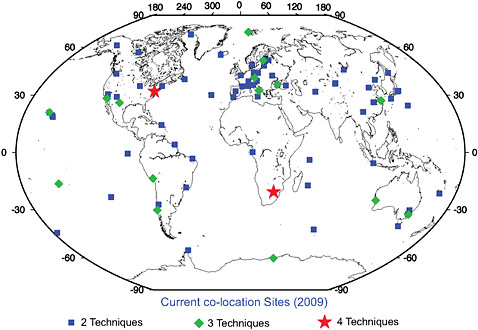
FIGURE 5.2 The current distribution of co-location sites. Only two sites currently have all four geodetic techniques contributing to the ITRF co-located. SOURCE: ITRF Product Center, http://itrf.ensg.ign.fr/.
|
1 |
ITRF Product Center: http://itrf.ensg.ign.fr/. |
|
2 |
Based on the difference between local tie measurements and geodesy estimates, assessed via the Weighted Root Mean Scatter of the tie residuals as results from the ITRF combination (Altamimi et al., 2002, 2007). |
The major limitation of a precise local tie is the surveyor’s ability to measure the internal geodetic instrument offsets. For example, for a GNSS/GPS-VLBI co-location, the local tie vector consists of the sum of the following three components: (1) the connection from the GNSS/GPS external reference point to the VLBI external reference point; (2) the VLBI internal offsets; and (3) the GNSS/GPS internal offsets. Segment (1) is the tie between the physically accessible points (or markers) that surveyors would normally measure. Segment (2) is the sum of all effects internal to the VLBI observing and data analysis systems that can introduce biases between the point referenced by VLBI data analysts and the external physical reference point used by surveyors. These include any sort of physical deformation of the VLBI antenna structure (due to temperature or the instrument’s own weight), especially those that cannot be distinguished from true height displacements or tropospheric refraction effects. Segment (3) is the sum of all effects internal to the GNSS/GPS observing and data analysis systems that can introduce biases between the point referenced by GNSS/GPS data analysts and the external physical reference point used by surveyors. These include direction-dependent errors in the signal propagation model due to antenna or radome effects and near-field long-wavelength multipath biases. The estimated uncertainty for each segment is probably no better than 1–2 millimeters; consequently, the overall error would be at best 3 millimeters for the local tie. Similar uncertainties apply to ties with SLR and DORIS. Consequently, technological innovation is needed to improve the ground-based methods for determining local ties and to regularly monitor the ties for changes.
Although terrestrial techniques might be limited by the uncertainty of measuring instruments’ internal offsets, dedicated space missions could provide a prime opportunity for future innovation in this domain. One such space mission currently being proposed by NASA’s Jet Propulsion Laboratory (JPL) is GRASP (Geodetic Reference Antenna in Space). GRASP is a proposed micro-satellite mission dedicated to the enhancement of all the geodetic techniques, with potential to improve the definition of the ITRF, its densification, and its accessibility. GRASP proposes to co-locate VLBI, GNSS/GPS, SLR, and DORIS sensors on a well-calibrated spacecraft (for which internal offsets are measured very accurately), to establish precise, stable ties between the key geodetic techniques used to define and disseminate the ITRF. GRASP also offers a potential solution to another difficult problem—the consistent calibration of the myriad antennas used to transmit and receive the signals of existing and future GNSS/GPS infrastructure. Improving GNSS/GPS signal modeling will benefit all precision applications of these systems. For example, simulations at JPL indicate that GRASP would improve by a factor of three the accuracy of orbit determination of GNSS/GPS satellites, of GNSS/GPS positioning, and of GNSS/GPS-based ITRF determination.
ITRF REQUIREMENTS TO MEET FUTURE NEEDS
To achieve the GGOS program goals and support future high-precision geodetic science, the ITRF needs to be robust and stable over many decades. Future scientific objectives drive a target accuracy of 0.1 millimeters per year in the realization of the origin of the ITRF relative to the center of mass of the Earth system (geocenter stability) and 0.02 parts per billion per year (0.1 millimeters per year) in scale stability. Achieving this goal will require improving the geographical distribution of the geodetic techniques, especially SLR and VLBI (GPS and DORIS are already well-distributed), as well as continued investment in the analysis of the data generated by those networks. For example, geocenter stability depends on accurate dynamic modeling and observations of the SLR satellites. Scale stability can be improved by minimizing ranging biases for SLR and better modeling of tropospheric refraction and antenna deformation for VLBI.
The anticipated increase in GNSS/GPS satellites over the next decade suggests the strong potential for GNSS/GPS to contribute to both geocenter and scale stability, but a combination of SLR and VLBI will also continue to be required. Currently, VLBI provides the only stable
long-term determination of the orientation of the Earth relative to the stars. SLR and VLBI provide the determination of the ITRF scale, and SLR provides the only determination of the origin. GNSS/GPS and DORIS are improving and may at some point provide comparable contributions to the origin and scale components. The GNSS/GPS scale will be more difficult to improve because it is dependent on the GNSS/GPS satellite antenna phase center offsets. These offsets need to be independently determined, either from pre-launch laboratory testing or more precise modeling of the electromagnetic environment of the satellite-transmitting antennas (assuming that the ITRF scale is already provided by SLR and VLBI), rather than being estimated from the GNSS/GPS data, as is currently the procedure (Schmid et al., 2005). SLR tracking of the GNSS/GPS satellites with retroreflectors can also be used in direct combination to separate orbit and antenna signals, hence it is important to install retroreflector arrays on future GPS satellites. Such arrays are already on the current GLONASS, GIOVE, and COMPASS satellites and are planned for all future Galileo satellites.
In the overall context of the goal to achieve an ITRF tied together at the one-millimeter level, a preliminary study was conducted to scope the size and distribution of the fundamental stations over a global network that would be required (Pavlis, 2008; Pavlis et al., 2008a). A fundamental station for the purposes of this report is a core geodetic ground station with at least one geodetic VLBI telescope; an SLR station (with some stations having LLR capability); at least three GNSS/GPS receivers to provide local tie information and monitor site deformation; a DORIS beacon; terrestrial survey instruments to determine and monitor local ties to the millimeter level; a superconducting or, preferably, an absolute gravimeter; meteorological sensors; and a variety of other sensors, such as seismometers, tiltmeters, and water vapor radiometers (see also Plag and Pearlman, 2009). The initial simulation was limited to considering the contributions of co-located VLBI and SLR stations, because these two techniques together can define completely the ITRF in terms of scale and origin, as well as Earth-orientation parameters (Earth rotation and polar motion). From a well-distributed group of 32 sites that comprise the maximal size network to be examined, three additional experiments considered reducing that network to 24, 16, and 8 sites. The study considered only the SLR from the two current LAGEOS satellites, and the results, illustrated in Figure 5.3, indicate that the ITRF accuracy goals can be achieved with approximately 24 stations. Beyond that number, there is little additional benefit in performance, although additional sites would improve robustness in the case of station outages.
Recommendation. Based on these results, the committee recommends that the United States should work with its international partners to increase the number of multi-geodetic technique sites (particularly co-locating VLBI and SLR), with a goal of reaching a global geodetic network of at least 24 fundamental stations.
While the simulation does not include GNSS/GPS, the inclusion of GNSS/GPS with the co-located SLR and VLBI stations is critical (and easily accomplished) for densification of the ITRF and the propagation of the resulting ITRF to the users, since most users will have access to the ITRF only through GNSS/GPS. Similarly, co-location with DORIS is essential for the most accurate applications of the DORIS technique. It is possible that a more complete simulation that includes the effect of GNSS/GPS may decrease the number of fundamental sites that are needed. Preliminary studies also indicate that SLR tracking to GNSS/GPS satellites can improve considerably the contribution of SLR to the precision of the ITRF, highlighting the importance of including laser reflector arrays on future GNSS/GPS satellites (Pavlis et al., 2009). Inclusion of laser retro-reflectors on GPS Block III satellites has been proposed formally by several U.S. government agencies, and planning and analysis is underway at the time of publication of this report to accomplish this. The
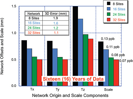
FIGURE 5.3 Estimating the size of the needed global fundamental station network from simulations. As the size of the network is increased from 8 to 32 stations, the accuracy of the determination of ITRF, in terms of origin and scale, is improved, but the improvement is relatively modest with more than 24 sites. This indicates that the ITRF accuracy goals can be largely achieved with approximately 24 stations with co-located SLR and VLBI stations. SOURCE: Courtesy of E. Pavlis, NASA.
reflectors could help specifically to improve the GPS satellite transmitter phase center modeling and to refine orbit modeling.
REGIONAL REFERENCE FRAMES AND THEIR RELATIONSHIP TO THE ITRF
Regional and national geodetic reference systems are essential for a variety of civil, legal, and public safety applications. These systems, however, have been traditionally realized through extensive ground-based surveys, are expected to have significant errors at the national scale (due to the accumulation of error inherent in leveling surveys), and are not always mutually consistent. Since the start of the ITRF development and the advent of improved positioning, however, national geodetic agencies have undertaken significant efforts to redefine and modernize continental and national geodetic systems so that they are compatible with the ITRF. For example, the European Terrestrial Reference System 1989 (ETRS89), the North American Datum of 1983 (NAD83), the Geocentric Datum for Australia (GDA), and other national geodetic systems are linked to the ITRF through conventionally adopted transformation parameters and formulas, and are often defined by fixed coordinates at a given epoch.3 For example, NAD83 is now defined in terms of a 14-parameter transformation from ITRF96. Regional organizations,
such as the European Reference Frame (EUREF) and the North American Reference Frame (NAREF), are represented within the IAG structure through their representation in IAG Commission 1. These regional entities play a major role in redefining regional and national datums and their relationship to the ITRF.
From 1987 to 1997, the National Geodetic Survey (NGS), in cooperation with other federal, state, and local surveying agencies, conducted a resurvey of the United States using GPS observations often referred to as High Accuracy Reference Networks (HARNs). Continued improvements in GNSS/GPS technology and requirements from the users of spatial data will eventually require a transition to an improved reference frame based on the ITRF. Positions relative to the ITRF differ from the existing NAD83 by approximately one meter in horizontal position and one meter in ellipsoidal height. NGS already publishes ITRF coordinates for all Continuously Operating Reference Stations (CORS), and will implement, over the next 3–5 years, an adjustment to include the HARNs and other GPS data submitted to NGS.
MODERNIZING THE NORTH AMERICAN DATUM (NAD)
The North American Datum 1983 is a common horizontal reference frame for the North American continent that is legally recognized by the United States and Canada. It is a fundamental element of the National Spatial Reference System (NSRS). Based on the first satellite geodetic results from early Doppler tracking and data from a few VLBI stations in the 1970s, the NAD83 took the North American reference frame into the space age, making obsolete the older NAD27 system that was based on ground-based classical surveys. Twenty-five years later, it would be timely and appropriate to upgrade the NAD system again, taking advantage of the latest global and national geodetic observations and geophysical models. The NAD83 differs from the ITRF at the level of one meter, a very large number considering the approximately one-millimeter level of precision of today’s geodetic techniques.
The difficulty for the United States and Canada is that the North American plate rotates, with the result that the coordinates of some stations would change by as much as one meter in 20 years. Fortunately, the rotation of the North American plate is highly stable and is well-understood by geodesists, so the effect of the plate rotation can be taken into account to provide stable coordinates. A NAREF working group of the IAG led by the U.S. NGS and Natural Resources Canada (NRCan) has researched ways to improve the NAD system. The working group, called “Stable North American Reference Frame,” is a collaboration between the NGS, NRCan, and university researchers who are experts in the latest geodetic techniques and modeling of geophysical effects. The participation of university researchers had been facilitated by funding from the U.S. National Science Foundation in recognition of the critical need for reference frame improvement for the scientific objectives of the EarthScope program. In addition, the NGS provides a service that enables users throughout the United States to compute the effect of modeled geophysical surface motion as a function of position, a service designed to bring station coordinates to rest after the correction is applied.
The NGS has to work within the legal definition of the NAD83, which was designed before the advent of the GPS in the 1980s. Modern surveyors typically use GNSS/GPS and do not necessarily need to use classical survey markers now that NGS provides data and coordinates from its CORS network. Nonetheless, in most areas, property laws govern the use of ground markers, which should be maintained on that basis. Furthermore, in areas where ground markers undergo large displacements as a result of geological processes, recovery and re-survey of these markers is a precious source of scientific information. The committee recognizes the vision and considerable efforts of NGS in modernizing the NSRS and encourages further developments to modernize the NAD system.
|
BOX 5.2 Gravity for the Redefinition of the American Vertical Datum (GRAV-D)a NOAA’s National Geodetic Survey (NGS) has a federal mandate to provide accurate positioning, including heights, to all federal, non-military mapping activities in the United States. Accurate heights are critical to many scientific endeavors but are particularly important to understanding and protecting low-lying coastal areas, which are subject to flood hazards. In 2007, NGS embarked on the GRAV-D project to determine the gravity-based vertical datum (elevation) with two-centimeter accuracy for much of the country. Because of the fundamental connection between the Earth’s gravity field and the definition of height above mean sea level (see Figure 1.2), complete gravity coverage of the continent is needed to connect the geometric height system measured by GNSS/GPS to the physical height system referred to as the geoid. The goal of GRAV-D is therefore to measure the Earth’s geoid. “The geoid is theoretical only. You can’t see it, touch it or even dig down to find it. Simply put, the geoid is the natural extension of the mean sea level surface under the landmass. We could illustrate this idea by digging an imaginary trench across the country linking the Atlantic and Pacific oceans. If we allowed the trench to fill with seawater, the surface of the water in the trench would represent the geoid. Not a bad way to imagine the geoid, but in reality not something we could easily do” (Natural Resources Canada).b The GRAV-D project consists of three major campaigns:

|
The NGS Gravity for the Redefinition of the American Vertical Datum (GRAV-D) project to modernize the national height system also is related to modernization of the NAD (Childers et al., 2009b; see Box 5.2). In effect, GRAV-D would provide the data necessary to define the national height datum as the new NAD ellipsoidal surface plus a geoid correction, modeled using gravimetric measurements. The combined NAD and geoid correction model would then be part of a new NSRS that would be consistent with the ITRF and also would meet the needs of the most demanding applications, including scientific experiments and monitoring for natural hazards. One aspect of this modernization that the NGS cannot deal with (at least not directly) is the legal definition of the NAD83. Such a radical improvement to the NAD might require Congressional legislation to redefine the national reference system; if that is the case, the committee urges that initiatives to propose such legislation be taken in consultation with the NGS.


