
The Blue Grass Chemical Agent Destruction Pilot Plant’s Water Recovery System
BACKGROUND
The design for the Blue Grass Chemical Agent Destruction Pilot Plant (BGCAPP) at the Blue Grass Army Depot near Richmond, Kentucky, is complete, and as of this writing the facility is under construction and about 50 percent complete. The planned operational life of BGCAPP is 3 to 5 years, beginning in 2017.1 A detailed description of the design is beyond the scope of this report. A general description of the interim design can be found in the National Research Council (NRC) report Interim Design Assessment for the Blue Grass Chemical Agent Destruction Pilot Plant (NRC, 2005). Although the description of the unit operations in the 2005 report is accurate, the present design is somewhat different, due mostly to reductions in the number of various types of process equipment.
In the demilitarization process planned for BGCAPP, the chemical agents—GB, VX, and mustard agent H—will be neutralized with hot caustic (for GB and VX) or hot water (for mustard agent H) after being removed from the munitions. Under the terms of the Chemical Weapons Convention, the products of this neutralization, called hydrolysates, must be further treated before they can be released for final disposal. Some of the energetics from munitions will also be neutralized on-site, including energetics from projectile bursters, rocket fuzes, and rocket propellant that has been contaminated with chemical agent. This energetics hydrolysate will be blended with agent hydrolysates prior to being processed by supercritical water oxidation (SCWO).
In the SCWO process to be used at BGCAPP, water will be heated to 650ºC (1200ºF) and pressurized to 230 atmospheres (3,400 pounds per square inch gauge [psig]), well above its critical point of 374°C (705ºF) and 218 atmospheres (3,204 psig), whereupon it becomes supercritical. This occurs in a reactor vessel, which at BGCAPP will be a Hastelloy C-276 tube that is 7.625 inches in diameter and 120 inches in length. Oxygen and the blended hydrolysates are introduced into the reactor along with the supercritical water. The hydrolysate blend will have a residence time of about 15 seconds in the reactor.2
The SCWO process can best be understood by thinking of supercritical water as a highly pressurized gas. Under these conditions, oxygen is highly reactive and will oxidize the elements in the hydrolysates into their most stable oxidized forms—carbon will be oxidized into carbon dioxide, hydrogen into water, and the sulfur and phosphorus into sulfates and phosphates. Organic materials, normally insoluble in water, volatilize at SCWO temperatures and are miscible in the supercritical water. Inorganic salts, which
_____________________
1Neil D. Frenzl, Surajit Amrit, P.E., and John W. Barton, Bechtel Parsons Blue Grass, “Blue Grass Chemical Agent-Destruction Pilot Plant Water Recovery System (WRS), RO: Addendum,” briefing to the committee, July 20, 2011.
2Dan Jensen and Kevin Downey, General Atomics, “SCWO: Overview of Design and Review of Prior Test Results,” briefing to the NRC standing Committee on Chemical Demilitarization, September 14, 2011.
normally dissolve and ionize in liquid water, do not volatilize and remain suspended as solids in the supercritical water. To prevent these salts from adhering to the wall of the reactor and eventually blocking the flow through the reactor, other salts will be added to form eutectics, which will keep the salts molten so that they flow through the reactor. At the end of the reactor, the pressure and temperature will be reduced and the water will return to a subcritical state. At this point, the salts will re-dissolve and the gases will separate from the liquid.
The SCWO environment is highly reactive and corrosive. Sacrificial titanium liners will be inserted into the reactor to protect the reactor walls. These will be replaced periodically as they corrode, depending on the agent being processed. The corrosion products from the liner will exit the reactor as titanium dioxide (TiO2) particulates, which must be removed prior to treatment of the SCWO effluent in the water recovery system (WRS). The exact titanium content in the SCWO effluent will depend on the agent being processed.
The SCWO process uses large quantities of water, which are continuously flowing through the reactor. To conserve water, the SCWO effluent will have the salts filtered out by the WRS by means of reverse osmosis (RO), and the recovered water will be recycled for use as quench water for the SCWO reactor.
In the RO process, water is forced through a membrane by pressurizing it above the membrane’s osmotic pressure. The membrane is designed to reject salts and to pass water only. The water passed through the membrane is called permeate, and that left on the input side of the membrane is called RO reject. As the salt concentration increases in the RO reject, the osmotic pressure increases, and greater pressure is required to force the water through the RO membrane and separate it from the salts, driving up the amount of energy used by the WRS. The BGCAPP design anticipates that about 70 percent of the water can be recovered by this technique. An examination of this process is the main focus of this letter report.
Until now, RO technology has not been employed in chemical demilitarization operations to recover water from a plant effluent. Because RO membranes and equipment are susceptible to failure from chemical attack, fouling, and other mechanisms, the Program Manager for Assembled Chemical Weapons Alternatives (PMACWA) requested that the National Research Council review the BGCAPP WRS design to identify possible issues related to the operability and reliability of the planned WRS.
SCOPE OF THE REPORT
This report focuses solely on the BGCAPP WRS. The scope of this study is limited to WRS operations, which begin when SCWO effluent and steam and cooling blowdown water enter the pretreatment system and end when the purified water exits the RO units. The input stream from the SCWO is assumed to be as described in earlier BGCAPP reports and in this report. The characteristics of the SCWO effluent flowing into the WRS are vitally important to the operation of the WRS, but any assessment of the SCWO process itself is beyond the scope of this study. Similarly, any additional treatment of the WRS effluent after exiting the RO units and prior to disposal is beyond the scope of this study.
The statement of task for this study (presented in full in Attachment A) initially required the committee to:
- Obtain information from the equipment vendor on water recovery system (WRS) installations that treat comparatively similar effluents to those at BGCAPP.
- Contact a representative industrial installation to review its reverse osmosis (RO) system operational and maintenance history, and determine the degree to which operability has been acceptable.
- Ascertain the likelihood that the quality of the recycled water will meet requirements for its re-use as quench water in the plant.
- Review materials of construction to determine whether adequate performance can be expected over the anticipated operational life of BGCAPP, specifically addressing potential concerns for corrosion, fouling, and stress cracking.
- Produce a letter report on determinations resulting from the above examinations.
The committee is composed of members with decades of experience and broad knowledge of the use of RO systems to treat waters in a wide variety of settings around the world. Several committee members have long been involved in industrial applications of RO systems. Regarding the first two items in the statement of task: based on members’ extensive experience and knowledge, the committee judged that there are no representative industrial applications that could be used as any meaningful basis of comparison to the RO application planned for BGCAPP. The committee did query the RO vendor chosen by BGCAPP as to whether it had ever treated effluents similar to those that will be treated at BGCAPP. The vendor had never treated anything similar to the unique compositions of the BGCAPP SCWO effluents.
In the course of performing its work, the committee obtained details about the SCWO process only insofar as that process affects the process stream that the WRS will treat. In reviewing and assessing the BGCAPP WRS, the committee recognized the following:
- The footprint for the RO system in the building is limited by the present design;
- The BGCAPP design is complete and construction is underway, making significant changes to the design challenging;
- This RO system will only be operational for 3 to 5 years, until all the munitions are destroyed and the resulting hydrolysate has been treated; and
- Any modifications to the design will necessitate amendments to the present Resource Conservation and Recovery Act permits, which govern plant operations, and will require negotiations with the Kentucky Department for Environmental Protection.
The remainder of this report describes and reviews the design of the RO pretreatment system, the RO system, and the materials of construction (MOC) selected for the WRS. The committee’s findings and recommendations are incorporated in the text near the discussion that supports them.
EFFLUENTS EXPECTED FROM THE SCWO SYSTEM
The SCWO effluents are expected to be salt solutions with a range of 1 to 3 percent dissolved solids content, consisting primarily of sodium chloride, sodium sulfate, and sodium dihydrogen phosphate. The SCWO effluents are also expected to contain suspended solids primarily consisting of the following:
- Titanium dioxide from the nerve agent campaigns,
- Iron oxide transported along from the mustard agent-filled projectiles during the mustard campaign, and
- Precipitates that form from waste constituents such as calcium, aluminum, and phosphate.
Tables 1 through 3 show the results of analyses of SCWO effluent performed in 2004. The hydrolysates for these analyses were produced by the neutralization of actual agent at an Army laboratory, were blended with energetics hydrolysate, and were then treated with an SCWO unit at a General Atomics site in its test SCWO unit.
Table 1 Liquid Effluent Analyses for GB SCWO Performance Tests
| Analyte | Units | 9/15/2004 06:40 Result | 9/16/2004 00:30 Result | 9/16/2004 12:00 Result | 9/16/2004 14:30 Result | Tap water Result |
| TOC(1) | mg/L | 1.5 | 1.7 | 1.8 | 1.4 | NA |
| TOC(2) | mg/L | 1.4 | 1.7 | 1.6 | 1.4 | NA |
| TOC(3) | mg/L | 1.5 | 1.7 | 1.7 | 1.3 | NA |
| TOC(4) | mg/L | 1.4 | 1.5 | 1.6 | 1.4 | NA |
| Chloride | mg/L | 2,820 | 2,680 | 2,530 | 2,110 | NA |
| Fluoride | mg/L | 144 | 140 | 177 | 116 | NA |
| Aluminum | μg/L | 6,040 | 7,130 | 16,500 | 6,110 | 30 U |
| Calcium | μg/L | 22,000 | 27,300 | 26,300 | 17,100 | 52,400 |
| Chromium | μg/L | 161 | 62.7 | 296 | 292 | 3.0 U |
| Iron | μg/L | 615 | 220 | 1,110 | 1,120 | 10 U |
| Magnesium | μg/L | 8,330 | 10,600 | 10,200 | 6,580 | 21,200 |
| Molybdenum | μg/L | 25.0 U | 25.0 U | 25.0 U | 25.0 U | 5.0 U |
| Nickel | μg/L | 103 | 52.4 B | 114 | 206 | 4.6 B |
| Phosphorus | μg/L | 349,000 | 326,000 | 339,000 | 321,000 | 20 U |
| Potassium | μg/L | 4,970 B | 4,110 B | 4,070 B | 3,500 B | 3,870 |
| Sodium | μg/L | 5,480,000 | 4,970,000 | 5,110,000 | 4,860,000 | 76,400 |
| Sulfur | μg/L | 2,330,000 | 2,080,000 | 2,150,000 | 2,050,000 | 54,200 |
| Titanium | μg/L | 5,560 | 4,840 | 5,080 | 5,080 | 5.0 U |
NOTE: Analytical codes are J, analyte positively identified but result is approximate; U, undetected; B, analyte found in method blank, result not valid; X, estimated maximum possible concentration; TOC, total organic carbon.
SOURCE: Adapted from BPBG, 2005.
Table 2 Liquid Effluent Analyses for VX SCWO Performance Tests
| Analyte | Units | 10/14/2004 08:45 Result | 10/15/2004 09:30 Result | 10/16/2004 07:30 Result | 10/17/2004 07:00 Result |
| TOC(1) | mg/L | 0.16 J | 0.19 J | 0.23 J | 0.13 J |
| TOC(2) | mg/L | ND | 0.17 J | 0.24 J | 0.12 J |
| Analyte | Units | 10/14/2004 08:45 Result | 10/15/2004 09:30 Result | 10/16/2004 07:30 Result | 10/17/2004 07:00 Result |
| TOC(3) | mg/L | 0.08 J | 0.18 J | 0.22 J | 0.12 J |
| TOC(4) | mg/L | 0.10 J | 0.18 J | 0.22 J | 0.13 J |
| Chloride | mg/L | 4,020 | 3,570 | 3,940 | 2,280 |
| Sulfate | mg/L | 12,200 | 10,400 | 11,800 | 6,880 |
| Phosphate | mg/L | 743 X | 689 X | 712 X | 680 X |
| Aluminum | μg/L | 17,200 | 15,600 | 15,700 | 15,700 |
| Calcium | μg/L | 174 | 186 | 662 | 32,600 |
| Chromium | μg/L | 10.0 | 11.3 | 6.8 | 3.8 J |
| Iron | μg/L | 100 | 244 | 74.9 | 64.4 |
| Magnesium | μg/L | 60.4 | 96.3 | 18,300 | 21,800 |
| Molybdenum | μg/L | 5.0 U | 5.0 U | 5.0 U | 59.7 |
| Nickel | μg/L | 71.3 | 81.7 | 64.0 | 83.1 |
| Phosphorus | μg/L | 803,000 | 708,000 | 761,000 | 736,000 |
| Potassium | μg/L | 4,990 | 5,260 | 18,500 | 7,070 |
| Sodium | μg/L | 9,540,000 | 8,620,000 | 9,210,000 | 8,560,000 |
| Sulfur | μg/L | 4,380,000 | 3,870,000 | 4,090,000 | 3,870,000 |
| Titanium | μg/L | 22,000 | 22,000 | 23,100 | 23,200 |
NOTE: Analytical codes are J, analyte positively identified but result is approximate; U, undetected; B, analyte found in method blank, result not valid; X, estimated maximum possible concentration; TOC, total organic carbon.
SOURCE: Adapted from BPBG, 2005.
Table 3 Liquid Effluent Analyses for Mustard SCWO Performance Tests
| Analyte | Units | 9/25/2004 12:30 Result | 9/26/2004 10:00 Result | 9/27/2004 06:15 Result |
| TOC(1) | mg/L | 0.17 J | 0.20 J | 1.4 |
| TOC(2) | mg/L | 0.19 J | 0.19 J | 1.3 |
| TOC(3) | mg/L | 0.15 J | 0.20 J | 1.4 |
| TOC(4) | mg/L | 0.19 J | 0.18 J | 1.3 |
| Chloride | mg/L | 4,040 | 4,390 | 4,020 |
| Fluoride | mg/L | <2 U | <2 U | <2 U |
| Sulfate | mg/L | 10,900 | 11,800 | 10,900 |
| Aluminum | μg/L | 8,360 | 7,450 | 9,730 |
| Calcium | μg/L | 170 B | 231 B | 38,100 |
| Chromium | μg/L | 176 | 147 | 209 |
| Iron | μg/L | 633,000 | 542,000 | 790,000 |
| Magnesium | μg/L | 400 | 375 | 15,500 |
| Molybdenum | μg/L | 25.0 U | 25.0 U | 36.0 B |
| Nickel | μg/L | 363 | 281 | 234 |
| Phosphorus | μg/L | 1,790 | 1,750 | 1,940 |
| Potassium | μg/L | 7,520 B | 6,220 B | 10,100 |
| Sodium | μg/L | 8,040,000 | 8,140,000 | 8,150,000 |
| Sulfur | μg/L | 3,930,000 | 3,930,000 | 3,990,000 |
| Titanium | μg/L | 192 | 133 | 136 |
NOTE: Analytical codes are J, analyte positively identified but result is approximate; U, undetected; B, analyte found in method blank, result not valid; TOC, total organic carbon.
SOURCE: Adapted from BPBG, 2005.
The elements that will likely impact the RO system are indicated in Table 4.
TABLE 4 Concentrations of Elements Present in the Three Hydrolysates
| Element | GB | VX | Mustard Agent H | Possible Solids |
| Al | 6-16 | 25-27 | 7.4-9.7 | AlPO4 |
| Ca | 17-27 | 0.1-33 | 0.2-38 | (Ca)2(PO4)3 |
| Fe | 0.2-1.0 | 540-790 | Fe2O3 | |
| P | 320-350 | 708-803 | 1.7-1.9 | Ma PO4 |
| Ti | 4.8-5.5 | 22-23 | <0.2 | TiO2 |
| S | 2,050-2,330 | 3,870-4,380 | 3,930-3,990 | CaSO4 |
aM refers to “metal” and can be Al, Ca, Mg, etc.
The elemental concentrations in the hydrolysates will exceed the solubility product for minerals such as AlPO4, (Ca)2(PO4)3, and Fe2O3, which are the forms likely to be found when the hydrolysate is oxidized. If insufficient phosphate is available in the hydrolysates, then the precipitates formed are likely to be hydroxides. The mustard hydrolysate is supersaturated with CaSO4, so precipitation and scaling of the RO membrane with this solid is of concern when this solution is processed by RO as well. Precipitation of calcium by phosphate in GB and VX hydrolysates may reduce the concentration of calcium that may prevent CaSO4 precipitation from being a problem when these hydrolysates are processed by RO. If these substances are present as particulates in the SCWO effluent, they will be removed if the coagulation and filtration processes prior to effluents arriving at the RO unit are functioning properly.
How much of the iron, calcium, and aluminum solids will settle out in the hydrolysate storage tank and the SCWO effluent tanks prior to effluents arriving at the WRS pretreatment system is not predictable. This issue is discussed in detail below, in the “Pretreatment System” section of this report.
The SCWO effluents will have overall salt concentrations similar to those of brackish water, but the specific compositions of the effluents will be unique, coming as they do from the processing of chemical agent and energetics hydrolysates. Therefore, although experience from RO plants that treat brackish water and seawater can provide guidance about the challenges that might be expected in the BGCAPP WRS, such experience is not necessarily directly applicable to the planned BGCAPP WRS. The SCWO effluent to be treated by the WRS will be at a higher temperature (38°C/100°F) than the water treated at seawater desalination plants. This elevated temperature can be expected to increase water flux and influence the rejection of salts by the RO membranes. This, again, demonstrates that the effluents to be treated by the BGCAPP WRS are unlike any other process stream that has been treated by RO in other commercial and industrial settings.
In the course of its data gathering, the committee queried the vendor personnel about whether they had ever treated an RO influent similar to the expected SCWO effluents; they replied that they had not. Further, in the committee’s knowledge and experience, no water recovery system, industrial or otherwise, has ever treated effluent
streams like those that will be treated at BGCAPP. The committee’s judgment, based on the individual members’ expertise and data gathering, is that the SCWO effluents expected at BGCAPP will be unlike any other influent previously treated by an RO system to date.
Finding. The compositions of the expected supercritical water oxidation effluents to be treated at BGCAPP are unique, and similar effluents have never before been treated by reverse osmosis.
Finding. Whatever testing could be conducted of effluents similar to those expected from the supercritical water oxidation system would be beneficial to ensuring that the water recovery system operates as expected, or to uncovering problems prior to systemization. Identifying problems as early as possible reduces the risk of significant disruptions to the overall project schedule.
Recommendation. It should be investigated whether precipitates might possibly form as the supercritical water oxidation effluents are being processed by reverse osmosis (RO), and whether steps, such as suitable inhibitor addition, can be taken to prevent the development of RO membrane scaling problems.
DESCRIPTION OF THE WATER RECOVERY SYSTEM
The WRS will desalinate SCWO effluents, cooling tower blowdown, and steam boiler blowdown for reuse as quench water in the SCWO process. The system was designed:
- To operate with an efficiency of 70 percent water recovery with a maximum of 500 mg/L total dissolved solids (TDS) in the permeate, and
- To ensure one full day’s storage of RO permeate to permit SCWO operation in case the WRS is not operating.
To accomplish these operations, the WRS includes:
- Three SCWO effluent storage tanks where the effluent will be analyzed to ensure that the total organic carbon concentration is less than 2 parts per million (ppm);
- A conventional pretreatment system consisting of coagulant and antiscalant addition (dual pumps on each unit), media filtration (six units), and canister filters (three) prior to the RO units;
- Three spiral wound reverse osmosis units (two operational, one spare); and
- Storage tanks used to hold RO permeate to clean the RO membranes periodically.
Figure 1 shows the flow of material from hydrolysis, through the SCWO process, up to the pretreatment step in the WRS. It also indicates where the cooling tower and steam blowdown is blended with the SCWO effluent. The dashed arrows indicate changes recommended by the committee (discussed in more detail below): namely, two
RO bypasses should be added, one to redirect blowdown water directly to the blowdown-water holding tanks or the RO reject tank if the water softener fails, and the other to divert softened water directly to RO permeate if water quality allows. Figure 2 shows the flow of material through the WRS. The arrow showing the addition of coagulant was added by the committee for clarity.
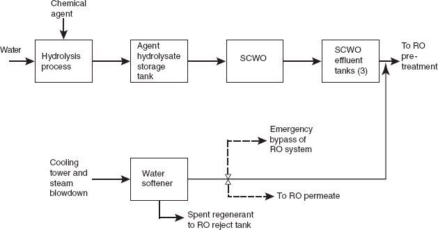
FIGURE 1 The flow of material from hydrolysis, through supercritical water oxidation (SCWO), up until the pretreatment step in the water recovery system (WRS). The dashed lines show changes recommended by the committee, as discussed in this report. NOTE: RO, reverse osmosis.
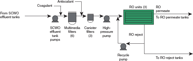
FIGURE 2 Process flow diagram for the BGCAPP water recovery system (WRS) including the pretreatment and reverse osmosis (RO) system (modified by the committee to add the coagulant insertion point). SOURCE: Neil D. Frenzl, Engineering Manager, Bechtel Parsons Blue Grass, and Surajit Amrit, P.E., Mechanical Engineering Lead, Bechtel Parsons Blue Grass, “Blue Grass Chemical Agent-Destruction Pilot Plant Water Recovery System (WRS), RO System Overview and Material of Construction and Related Issues,” presentation to the committee, July 19, 2011.
The overall operation of the WRS will be monitored by the facility control system. Items monitored will include the following:
- Temperature indication for the feed to the RO units,
- Flow indication for the feed to and discharge from the RO units,
- TDS concentration (through conductivity monitoring) of RO permeate,
- Differential pressure across the RO unit (feed versus reject),
- Differential pressure across the multimedia filters and canister filters, and
- Proportional flow ratio and total flow rate indication for the caustic injection system (BPBG, 2009).
PRETREATMENT SYSTEM
Water Softening
Two streams will be blended to form the WRS influent—that is, (1) SCWO effluent and (2) cooling tower and steam blowdown water. Removing the calcium in the RO influent stream is necessary before it arrives at the RO system because calcium could have a significant negative impact on the operation of the RO units.
Water softening will be used to remove the calcium (a water hardness component) from the cooling tower and steam blowdown water. According to BPBG (2007), ion exchange columns will be used to soften this stream prior to its being blended with the SCWO effluent (see Figure 1). Ion exchange softeners can produce water with a very low level of calcium. However, the level of residual calcium will be determined by the operating procedure of the ion exchange process—particularly (1) the amount of calcium leakage allowed in the softener effluent before regeneration and (2) the concentration and quantity of regenerant applied. The spent softener regenerant3 will be combined with RO reject water for final disposal.
The total calcium concentration in the SCWO effluent and softener effluent blend will have an important effect on water recovery from the RO process. It is also possible, however, that the effluent from the softener will have sufficiently low calcium content, making it suitable for blending directly with the RO effluent, bypassing the RO unit. This would reduce greatly the amount of water that must be processed by the RO system.
The hydraulic design of the RO process targets 70 percent recovery, but a higher recovery might possibly be achieved if the calcium in the ion exchange-treated cooling tower and steam blowdown water effluent is sufficiently low and there is minimal calcium in the SCWO effluent after pretreatment. The design recovery of 70 percent may lead to scaling of the membranes if substantial calcium remains in the softener effluent and/or if there is substantial calcium in the SCWO effluent after pretreatment.
The SCWO effluent from the processing of mustard agent hydrolysate had a high concentration of calcium, although it should be noted that only one valid analysis is presented in Table 3. This level of calcium combined with the high sulfate concentration shown in Table 3 indicates that CaSO4 precipitation may take place in the RO system
_____________________
3The regenerant is the waste solution resulting when a high-concentration solution of NaCl is used to renew the hardness removal capacity of the ion exchange resin. Typically the regenerant contains high concentrations of NaCl, calcium salts, and magnesium salts.
when mustard agent hydrolysate is being processed. The SCWO effluent from the processing of GB hydrolysate contained calcium, and one sample of SCWO effluent from the processing of VX hydrolysate also showed a high level of calcium (see Tables 1 through 3). It is possible that the concentrations of calcium may be substantially reduced by precipitation with phosphate before filtration, thus reducing the possibility of calcium scaling when the GB and VX SCWO effluents are being processed. To prevent scaling from calcium in the SCWO effluent, a polyphosphate chemical has been selected as an antiscalant for RO pretreatment at BGCAPP. Adequate pH control is also necessary for the effective control of scaling. For example, reducing pH to 5 or less would protect against RO membrane fouling from the precipitation of CaSO4/CaCO3.
Finding. Water softening of the cooling tower and steam boiler blowdown is essential. Otherwise, there could be catastrophic scaling and failure of the reverse osmosis (RO) system. If the ion exchange system is not functional, the calcium-laden blowdown water must not be blended into the RO feedwater without further modifications to the pretreatment and RO units.
Finding. The use of pH control is also a necessary component to protect against scaling. Using pH control in addition to the use of chemical antiscalants would provide the best scaling control.
Recommendation. It should be confirmed during systemization that calcium removal is complete and that softener monitoring and regeneration procedures have been established to avoid calcium mineral scaling in the reverse osmosis units.
Recommendation. The BGCAPP design should include a water bypass from the water softener around the reverse osmosis system in the event that the softener fails. The water should be returned to the blowdown-water holding tanks, or sent to the RO reject if the holding tank capacity is insufficient.
Finding. The reverse osmosis (RO) system hydraulic design target of 70 percent recovery assumes that there is no calcium in the RO influent. The actual level of calcium in the RO influent will depend on how the ion exchange softening process is operated and on the level of calcium in the SCWO effluent after pretreatment. The SCWO effluent does not pass through the softener, and its level of calcium could be substantial.
Recommendation. Additional reverse osmosis hydraulic design simulations (e.g., ROSA) should be considered using different levels of calcium in the feed, taking into account the calcium levels anticipated in the SCWO effluents, in order to establish the target level of recovery for each campaign.
Finding. If the quality of the softened water meets the requirements for use as quench water, then the softened water could bypass the reverse osmosis (RO) system and be injected directly into the RO permeate.
Recommendation. Regularly bypassing part of the softened water around the reverse osmosis (RO) system directly to the RO permeate should be considered, rather than
adding it to the RO feedwater. If this is done, the blended product water could still meet the total-dissolved-solids requirement of 500 mg/L, and the load on the RO system will be reduced. This may become important if other problems accelerate membrane fouling.
Coagulation of the Suspended Solids in the SCWO Effluent
Overview of Coagulation
The use of RO membranes requires some form of pretreatment in order to remove suspended solids and to reduce turbidity and the silt density index (SDI). Solids found in water are broadly grouped into two categories: suspended solids and colloids. Suspended solids are operationally defined as those that can be removed from water by filtration through a membrane with a 0.45 micron pore size, and colloids are solids that pass through such a membrane.
Many suspended solids and colloids can be stable suspensions that do not settle rapidly because of their small size, surface charge, and other factors. These suspensions must be destabilized by treatment with coagulants that aggregate the particles so that they can be removed by sedimentation and/or filtration. Chemical coagulants include aluminum and iron salts and both inorganic and organic polymers. The addition of coagulant may have to be followed with a gentle mixing step called flocculation to aggregate the solids and ensure that subsequent sedimentation and filtration processes work effectively. The interactions between coagulant chemicals, the water constituents, and the suspended solids are often difficult to predict. Thus, determining the best coagulant and dose usually requires laboratory testing to ensure that the system will function properly. It might also be necessary to add an organic chemical, called a filter aid, to improve filtration performance.
Two approaches are used for particle removal by coagulation. (1) The traditional method is flash-mixing–flocculation–sedimentation–filtration. In this method, the coagulant is added in a short-retention-time reactor (30 seconds to several minutes) with mechanical mixing. This flash-mixing step is followed by flocculation and sedimentation prior to filtration. Typical hydraulic retention times for flocculation are between 2 and 30 minutes, and for sedimentation they are 1 to 4 hours. (2) The second approach, direct filtration, includes in-line—that is, static—mixing followed by filtration. Direct filtration is less expensive to install but often is less efficient than flash-mixing–flocculation–sedimentation–filtration. However, direct filtration is often adequate for many applications, especially those that have low total suspended-solids concentrations and particles that aggregate well. The current BGCAPP design uses direct filtration with an in-line static mixer. The committee has identified two challenges with this approach.
The first challenge at BGCAPP is the large mass of suspended solids to be removed by the media filters. It appears from the water quality data in Tables 1 through 3 that the solids loading to the filters will be within proper design values for the GB and VX campaigns if aluminum and calcium do not precipitate. However, aluminum and calcium precipitation is likely, and the media filters could be rapidly overloaded with solids. During the mustard agent campaign, the media filters could also be overloaded by the iron particles in the mustard hydrolysate. How much iron, aluminum, or calcium solids will settle out in the various holding tanks and how much will be carried over into
the media filter cannot be predicted. If large quantities of iron, calcium, or aluminum arrive at the media filter, excessive filter backwashing will be required. This is discussed more fully below, in the section entitled “Particle Loading Challenges.”
The second challenge that the committee identified with respect to the direct filtration approach is that direct filtration (1) is more difficult to control than flash-mixing–flocculation–sedimentation–filtration, (2) is usually less efficient, and (3) requires more coagulants and filter aids. The use of additional chemicals increases the filter loading and the probability that these chemicals will be transported through the filtration process into the RO system, where they will be removed at the cost of more rapid RO membrane fouling.
Finding. The proposed pretreatment system for the reverse osmosis (RO) system must operate well in order for RO to be effective. The use of direct filtration as opposed to a flash-mixing–flocculation–sedimentation–filtration process creates additional challenges for successful operation.
Finding. If the final design retains the direct filtration process, the facility operators should plan to have a shakedown period before operating the pretreatment system on new or different influents. Jar testing and periods of reduced throughput should be expected during this shakedown period. At water treatment plants, such shakedown periods can last for several weeks.
Recommendation. Time should be scheduled to shake down the media filters at the start of each new agent campaign.
Choice of Coagulant
The committee is concerned about the choice of aluminum sulfate as the coagulant to be used to pretreat the SCWO effluent prior to medial filtration (BPBG, 2009). Aluminum sulfate and other inorganic coagulants such as ferric iron may not be effective in treating SCWO effluent. If aluminum sulfate functions as desired, it will form solid Al(OH)3, and also possibly form positively charged Al polymers that destabilize and aggregate the solids so that they can easily be removed by the tri-media granular filter. As shown in Table 1, SCWO effluent from processing GB is expected to contain approximately 330 mg/L of phosphorus, or approximately 1,000 mg/L of PO43+. Table 2 shows that the SCWO effluent from the VX campaign may have as much as 2,500 mg/L of PO43+, if all phosphorus is in the form of phosphate. Given these orthophosphate concentrations, both aluminum and ferric coagulants will likely be precipitated as AlPO4 and FePO4 instead of the Al(OH)3 and Fe(OH)3 that would normally form. The committee cannot predict whether AlPO4 and FePO4 will function as coagulants, but it believes that they may not be effective. Simply adding more coagulant to overcome the amount of coagulant required to react with the phosphate is not a satisfactory solution, because extremely large concentrations would be required and they would form precipitates that would overload the granular media filters. The exact amount of coagulant, the required pH for optimum coagulation, and the concentration of base (e.g.,
sodium carbonate) required for pH control to provide effective coagulation have not as yet been established.
Alternatives to aluminum coagulant that may find application at BGCAPP include (1) organic polyelectrolytes such as poly-DADMAC and EpiDMA that have been used as effective coagulants, and (2) polyacrylamide, poly-DADMAC, etc. However, organic polymer coagulants and filter aids may prove to be problematic because they may pass through media filters and foul the RO membrane. BGCAPP personnel have provided information from one of their vendors indicating that there may be an organic polymer coagulant that would not introduce the risk of passing through the filter and fouling the RO membrane (Avista, 2005). Another alternative to alum and ferric salts could be a preformed coagulant such as polyaluminum chloride (PACl). There is the risk that PACl would react with PO43+ in a manner similar to the way that alum and ferric salts would.
Finding. If the coagulation and flocculation processes do not reduce the silt density index below the value prescribed for the reverse osmosis (RO) membrane, then the RO system could fail to operate as planned because the RO membranes would foul too rapidly.
Finding. The coagulation system, as currently designed, has a high risk of functioning poorly for two reasons. First, if aluminum coagulant is used, coagulant-phosphate reactions in supercritical water oxidation effluent could lead to excessive filter loading rates. Second, because a high coagulant dose is intrinsically required for direct filtration, the coagulant could carry over from the direct filtration unit. Either of these two occurrences will cause rapid fouling of the reverse osmosis membranes.
Recommendation. When supercritical water oxidation effluent becomes available, the committee strongly recommends that jar tests be conducted with each effluent to validate the choice of coagulant.
Recommendation. Given the concerns about aluminum and ferric coagulants, a coagulant that does not react with phosphate should be considered. One possibility is an organic polymer coagulant that has been well tested with reverse osmosis (RO) systems. A second possibility is a preformed coagulant such as polyaluminum chloride.
Filtration Systems
Suspended solids that have been coagulated and flocculated must be filtered from the process stream before reaching the RO membrane. Today, the two most common filtration methods are membrane filtration and granular media filtration. Granular media filtration is planned for use at BGCAPP.
Comparison of Media and Membrane Filters
In earlier years, granular media filtration was the most common filtration method used with RO systems. Granular media filtration involves the gravity or pressure-driven filtration of feedwater through one or more layers of some combination of anthracite, sand, and garnet.
More recently, membrane filtration has emerged as an attractive alternative to granular media filtration. Membrane filters consist of porous membranes through which water is forced. The membranes are designed so that only water passes, while particulate contaminants are left behind. Membrane filtration facilities have a small footprint (as much as 20 to 60 percent smaller than that of conventional media filtration systems [Li et al., 2008]), usually do not require additional chemicals, have fewer operating requirements, and can be monitored and operated remotely. The filtration membranes most often used are either microfiltration (MF) or ultrafiltration (UF) hollow-fiber membranes. Despite the advantages of membrane filters, some RO plants use granular media filtration owing to its long history and its cost-effectiveness in certain circumstances.
Marked differences exist between the two filtration methods in terms of finished water quality, energy requirements, cost, ease of operation, design, and overall footprint. The quality of the feed stream is an important factor in selecting the type of filtration to be used. Granular media filtration is sensitive to influent water quality. Media filtration requires the addition of a coagulant to enable significant solids filtration, but it will still allow colloids and suspended solids to pass through (Brehant et al., 2002). Granular media filters are effective at removing suspended solids that are larger than 10 µm. For suspended solids smaller than 10 µm, the removal efficiency declines and depends on the nature of the particles, their charge being the most important characteristic. In contrast, membrane filters present highly effective selective barriers if an appropriate pore-size or molecular-weight cutoff is selected. The filter pore size is based on the size of the influent solids or on their molecular weights. Additionally, membrane filtration delivers stable effluent quality regardless of fluctuations in the solids concentration in the feedwater. They deliver effluent with turbidity less than 0.1 NTU4 and SDI levels below 1, whereas media filtration often cannot reduce SDI much below 3 (Brehant et al., 2002; Li et al., 2008). As the input quality worsens, the footprint of the multimedia filtration system required to process the influent increases. This is not the case with UF systems, which are not susceptible to variations in the influent quality.
Relative to media filters, membranes are more easily damaged by feedwaters with extreme pH or high temperatures, and, like media filters, must be backwashed periodically to maintain low transmembrane pressure. In general, the increased reliability of a membrane filter system is estimated to reduce the total effluent production costs by about 10 percent (Wilf and Schierach, 2001); however, initial capital costs for a membrane filtration unit are higher than for a media filtration unit, because the membranes are more expensive than media materials.
Operational Characteristics of Media Filtration Systems
Filtration rate and bed loading are the two key characteristics of media filters. Filtration rate is the overall water velocity through the granular media, and bed loading is the total mass of suspended solids removed and retained in the granular media before backwashing is required. The filtration rate impacts the removal efficiency and impacts the time between backwashes. Filtration rates of 2 to 5 gal/min-ft2 (GPM/ft2) are typical for water and wastewater treatment plants. Conservative and older designs use only sand
_____________________
4Nephelometric turbidity units.
as the medium and are restricted to the lower filtration rates, usually only 2 GPM/ft2. Designs for wastewater treatment, especially those for which filtration is not needed as a disinfectant, use higher rates, especially when mixed media are used. With multimedia (dual-, tri-, and mixed-media) beds, filtration rates are usually in the 4 to 5 GPM/ft2 range. Multimedia filters include anthracite coal in one or two sizes and densities, sand, and garnet sand (which is smaller and denser than normal sand).
Bed loadings of 1 lb/ft2 between backwashes are typical, although both the manner in which the particles are distributed throughout the bed and the concentration of particles that appear in the filter effluent play important roles in determining the actual loading that can be tolerated before backwashing. As the filter operates, suspended solids are removed and the head loss (pressure drop) through the bed increases. The concentration of particles that appears in the filter effluent depends on the conditioning of the influent to permit effective filtration. Instrumentation is usually provided to monitor head loss and effluent quality, and the process controller can be programmed to trigger a backwashing automatically when the head loss exceeds the design amount or when the quality of the filter effluent is no longer satisfactory. Alternatively, the filter can be taken off-line and the operator can initiate a backwashing manually. One measure of effluent quality for filters preceding an RO system is the SDI, because a sufficiently low SDI is essential to the good operation of an RO system. In the BGCAPP WRS design, the media filters are in closed pressure vessels and not in open tanks. This provides greater flexibility in operation and design, particularly for providing backwash water.
Finding. Granular media filters preceding reverse osmosis (RO) membranes need to be backwashed when the filter head loss exceeds the design value, or when the quality of the filter effluent is no longer acceptable for the RO system.
Granular media filters are typically backwashed at 15 to 20 GPM/ft2 for the range of temperatures found in drinking water treatment (5°C to 25°C/41°F to 77°F). This high velocity is needed to expand the bed as well as to provide sufficient turbulence to create collisions among media particles so as to release filtered solids. The backwash rate will need to be increased for the higher temperatures associated with the BGCAPP WRS (about 38°C/100°F), as water viscosity decreases with temperature, and this will result in more backwash water being required. With multiple pressure filters in parallel, it is possible to use filtered water for backwashing. In this situation, one of several filters is backwashed using the product water from the filters not being backwashed. This type of backwashing is one of the principal advantages of pressure filters.
Finding. The required BGCAPP filter backwash rate will be a function of temperature, and the quantity of backwash water required to clean a filter will increase as temperature increases.
Particle Loading Challenges
In practice, the concentration and type of solids in the WRS influent will determine the process conditions required to remove them. For example, the mustard agent hydrolysate may contain as much as 1,100 mg/L of iron particles as Fe2O3 as well
as calcium sulfate particles. Their concentrations will likely be reduced by sedimentation in the hydrolysate storage tank and in the SCWO effluent tanks; however, the extent of this reduction is unknown, and thus the concentration of these particles that will be fed to the media filter is also unknown. Also, approximately 10 to 50 mg/L of titanium dioxide solids are expected in the SCWO effluent, and up to 150 mg/L of aluminum and calcium phosphate precipitates may occur in SCWO effluent when GB and VX are processed. These concentrations may also be reduced as a result of settling in the storage tanks but, again, to an unknown extent. The storage tanks can be designed to include features that maximize sedimentation (e.g., the placement of tank inlets and outlets) regardless of these uncertainties. The size distribution and surface characteristics of these solids are also unknown, as is their removal efficiency in the filter after coagulation. Additional suspended solids may be produced by the coagulant that is used.
Finding. The level of solids that will be in the media filter influent, and the concentration of solids that will appear in the filter effluent as a function of time of filter operation between backwashes, represent very important unknowns relative to satisfactory media filter operation.
The importance of the solids loading factor can be illustrated by calculating the frequency of backwashing and the quantity of backwash water required, given some simplifying assumptions. An accumulation of 1 lb of solids per square foot of filter media is a generally accepted threshold for requiring backwashing. Usually either maximum head loss or an unacceptably high level of solids will appear in the filter effluent when this level of loading is reached. The actual threshold will be determined by the type of solids being removed by the filter, so this calculation is presented for illustrative purposes only.
In the BGCAPP design, there are six filters, with a total area of approximately 95 ft2, or 15.8 ft2 per filter. A 10-minute backwash time and a filter loading of 2 lb/ft2 have been assumed in the BGCAPP design calculations. Given the design operating rate of 1 GPM/ft2, the design loading of 2 lb/ft2 of filter surface will be reached once per day if approximately 180 mg/L of particles are removed. As discussed above, there is a potential for much higher particle concentrations in filter influent. If the concentrations of solids in the influent that require removal are much higher than 180 mg/L, or if the solids are poorly removed by the filter such that the actual loading threshold requiring backwashing is far less than the design loading threshold, the filters could require continuous backwashing—that is, they would always be operating in reverse, not filtering water, and therefore causing process failure.
An additional problem with the proposed design is the volume of water available for backwashing. With filter banks like the ones in the design, it is normal to use five filters to produce sufficient water to backwash one filter. In the current situation, five filters operating at 1 GPM/ft2 will produce only enough water to backwash at 5 GPM/ft2 instead of the 15 to 20 GPM/ft2 typically used; thus this option is not available at BGCAPP. Rather, it will be necessary to have a reservoir for filtered water that will be available for backwash operations, and backwash pumps to supply the water at the desired rate.
It is not apparent how the spent backwash water will be processed. Presumably it would be pumped to a holding tank in which the suspended solids could be settled out,
and then the supernatant could be recycled to the filter influent. The alternative of sending the spent backwash water to the RO reject is also available, but if the quantity of backwash water is large, this could greatly increase the problem of reject disposal.
Finding. For backwash operations of the filter media, it will be necessary to have available a reservoir for filtered water, along with backwash pumps to supply the water at the desired rate.
Finding. The selected filtration rate of 1 GPM/ft2 is conservative in view of the amount of water necessary to backwash the filter media.
Finding. The actual rate at which solids can be expected to accumulate in the media filters is unknown. The BGCAPP particle loading value of 2 lb/ft2 is not conservative but is based on a lower filtration rate of 1 GPM/ft2, so higher loadings may be possible.
Finding. A reduction of suspended solids may occur by means of sedimentation in the hydrolysate storage tank and the supercritical water oxidation effluent tanks. These tanks can be designed to include features, such as the placement of tank inlets and outlets, that maximize sedimentation.
Recommendation. The inlets and outlets of the supercritical water oxidation effluent storage tanks and the hydrolysate holding tanks should be designed to maximize solids removal by means of sedimentation to reduce the solids loading of the granular media filter. Sufficient volume below the inlets and outlets should be provided for solids storage to ensure that particles do not escape, especially as a slug.
Finding. Preliminary calculations suggest that more backwash water might be needed than can be produced by the filters if there is not sufficient removal of particles in the hydrolysate holding tank and the supercritical water oxidation effluent tanks.
Recommendation. Means to provide sufficient sedimentation should be ensured, or other procedures used upstream of the multimedia filters, so that these filters will not be overloaded with solids.
Clarifiers
Clarifiers are tanks that provide an opportunity for suspended solids to settle out by sedimentation under quiescent conditions. When used, clarifiers are installed in the process flow prior to filters in order to remove particles and to pretreat RO influents, either when suspended solids concentrations are high or when the suspended solids are particularly difficult to remove. The BGCAPP design does not currently include any clarifiers.
The details of clarifier operation vary depending on the design of a given clarifier. In a circular clarifier, the water enters the center of the tank, and the clarified water overflows the tank edges and is collected. Clarifier design is based on overflow rate—the rate at which water flows over the edges of the clarifier—and solids flux. Operationally,
overflow rate is calculated as the flow rate through the clarifier divided by the area available for sedimentation. For ideal clarifiers, the overflow rate is the upward liquid velocity. Particle settling velocity is typically calculated using Stokes’ law and is a function of particle diameter and particle density. For typical drinking water and wastewater treatment applications, overflow rates of 800 to 1,200 gal/ft2/day are typical. In metric units, the overflow rate is expressed in meters per hour or meters per day.
The second clarifier design parameter is the solids loading rate, usually expressed as a solids flux. Typical design bases for solids flux for wastewater treatment plants are 25 to 40 lb/ft2-day. The exact value depends on the nature of the solids and on how well they settle. Usually, either overflow rate or solids flux controls a clarifier design, but not both simultaneously. In the case of a BGCAPP clarifier, the overflow rate would be the controlling parameter for the clarifier design. With the normal range of overflow rates stated above, the influent suspended solids would have to be as high as 2,500 to 3,000 mg/L for the solids flux to become limiting.
The original BGCAPP WRS process design included a clarifier with an overflow rate of 470 gal/ft2/day and a clear well,5 but both have since been removed. Box 1 describes why the clarifier and clear well were removed from the BGCAPP WRS design.
Finding. The absence of a clarifier in the process flow increases the likelihood of overloading the filters with solids.
Finding. The insertion of a clarifier in the process stream would reduce the likelihood of filter problems from excessive solids loading of the filter.
Recommendation. The conversion of supercritical water oxidation (SCWO) effluent storage tanks into clarifiers should be considered. Although this modification will not reduce the solids that are formed during coagulation, it will ensure good removal of solids that readily settle out of the SCWO effluent, thereby decreasing the solids loading on the media filters. The conversion into clarifiers would involve inlet and outlet design, as well as other factors such as consideration of solids accumulation, removal, and appurtenances to improve solids removal.
Potential for Microbial Growth Between the SCWO Reactor and the RO System
Another concern in a standard industrial RO water recovery system is microbial growth downstream in the system prior to the RO membrane because such microbial growth can cause RO membrane fouling. The committee believes that such fouling is very unlikely, because the composition of the agent and energetic hydrolysates will not be conducive to sustaining live microbes, and the extreme temperature and pressure in the SCWO reactor will destroy any live microbes in the hydrolysate streams. There is, however, some potential for the introduction of microbes by way of the cooling tower and steam blowdown water.
Should microbial growth occur, the installation of a chlorination system would be a simple solution. The addition of chlorine could be followed by dechlorination
_____________________
5A clear well is a storage tank. In this case, it was a tank that would have held effluent from the clarifier.
BOX 1 Excerpt from Bechtel Parsons Blue Grass Trend Notice TN-24915-06-00126
Trend Description
Deletion of the SPB [SCWO Process Building] Water Recovery System (WRS) clarifier and clear well tank is covered by this trend. Deletion of the clarifier requires increasing the size of the multi-media filters located upstream of the Reverse Osmosis (RO) units to ensure the RO units are not exposed to excessive solids loading. If the clarifier is deleted, there is no longer a need for the clear well tank.
The clarifier was included in the intermediate SPB design to remove solids levels anticipated for all munitions campaigns. This was based on the solids data available at that time. However, based on more recent data, solids levels (600 to 700 ppm) requiring a clarifier are only anticipated for the H campaign. The H campaign is relatively very short and is anticipated to have a duration of approximately 12 to 14 weeks. Therefore, the technical viability of deleting the clarifier and increasing the size of the multi-media filters was investigated. Two qualified bidders were contacted to determine the feasibility of this optional approach. Both bidders indicated that deleting the clarifier is technically feasible. One bidder indicated a slight increase in filter size would be required (from 36” to 48” diam.). The second bidder indicated that a significant increase would be needed (to 8’ diam.). This trend is based on increasing the size of the filters to 48” diameter as this is a technically feasible approach.
Due to increased filter solids loading during the H campaign, the total quantity of backwash water is estimated to increase by 430,000 gallons. Backwash water is discharged to the existing RO Reject Tanks and trucked offsite for treatment and disposal.
Trend Justification (Impact if this trend is not approved)
Since the clarifier is not needed during the vast majority of the operations duration (not needed during the VX and GB campaigns) and a significant net cost savings is realized, it is recommended that the clarifier be deleted. Eliminating the clarifier and clear well tank and increasing the size of the multi-media filters result in a more cost-effective design. Based on input obtained, the equipment only estimated cost savings is approximately $380,000.
Elimination of the clarifier results in a more efficient design as a major piece of equipment is eliminated. Construction, Systemization, Operations, Maintenance and Closure efforts would be significantly reduced.
A secondary and significant benefit resulting from the deletion of the clarifier and the clear well tank is that a significant amount of floor space would be made available in the SPB. This space could be used during the Construction, Systemization, Operations and Closure phases of the project resulting in increased efficiencies. An open area of roughly 1,000 sq. ft. would be created.
__________________
SOURCE: Reprinted from BPBG (2006), p.1.
immediately prior to the RO membranes, although dechlorination might not even be necessary given the short operational life span planned for the WRS, provided that the free chlorine concentration is below 0.1 to 0.5 ppm, or the concentration of chloramines is below 2 to 5 ppm.
Finding. Microbial growth downstream of the supercritical water oxidation reactor and prior to the reverse osmosis system is not likely. If microbial growth does occur and is deemed a problem, adding a chlorination system would be a simple solution.
Finding. If chlorination were added prior to the reverse osmosis (RO) membrane, for the short planned operational life of the water recovery system, removal of chlorine prior to the RO membrane might not be necessary if the free chlorine concentration were below 0.1 to 0.5 ppm, or the chloramine concentration were below 2 to 5 ppm.
Managing Pretreatment Risks
Approaches typically used by the water industry to manage pretreatment risks involve tests that are performed using actual filter influent at both bench and pilot scales. In the absence of performing on-site tests or obtaining site-specific water samples that can be used in laboratory tests, synthetic influent solutions are prepared in the laboratory by adding appropriate masses of salts and surrogate particles to laboratory deionized water.
Laboratory Particle Size Analyses
An understanding of the size of particles present in RO influents greatly facilitates the proper selection of the prefiltration process to be placed upstream of an RO unit. Large particles are easily removed by multimedia filtration, whereas submicron colloids are better removed by microfiltration. Nanoparticulate species are best removed by ultrafiltration.
Laboratory Particle Stability Analyses
An understanding of the relationship between particle surface charge, stability against aggregation, and the chemistry of added coagulants is critical to optimizing multimedia filter performance. Bench-scale coagulation jar tests are normally conducted to evaluate the optimal coagulant selection (e.g., ferric, alum, PACl, or polymer), appropriate coagulant dose, and any pH adjustment needed to achieve maximum particle removal.
Laboratory Particle Filterability Analyses
Bench-scale column filtration experiments can be helpful in selecting the filter media size, type of medium (sand, anthracite, garnet, synthetic media, or others), and combinations of media. In practice, filter media selection and optimization should be done using coagulant(s), dose(s), and pH selections to confirm and optimize filter performance, expected filter run times, and backwash requirements.
Pilot-Scale Testing of Media Filter Performance Using Actual RO Influent
Bench-scale experiments conducted in the laboratory using actual or synthetic RO influents provide somewhat idealized results. Ultimately, pilot-scale tests conducted in the field using the actual RO influent are the most effective method for mitigating risk by evaluating and optimizing system design and operation at full scale. Successful filter performance would be defined by filter effluent with an SDI value less than 2 as a safeguard against colloidal fouling of the RO membranes. A low SDI does not protect against scaling, which requires chemical antiscalants and pH control as discussed above.
Risks with the BGCAPP Media Filtration Design
Media filtration is a mature process and is generally well understood. Nevertheless some risks remain in using this technology. The major risk is that of overloading the filter with suspended solids, resulting in the need to backwash the filter too frequently.
Another potential problem is the inability to backwash the filter properly. This problem can occur when the suspended solids being removed agglomerate into large solids that cannot be broken apart during backwashing. The solids continue to grow and eventually must be manually removed. These large solids, sometimes called mud balls in municipal treatment situations, are usually caused by the excessive use of coagulants or by routinely backwashing with too little flow or for too short a time.
Another risk is the loss of media, usually during backwashing. It is common for media filters to lose their media over months or years. The media are not difficult to replace, and mechanical designs of filtration systems must anticipate media replacement by allowing access to equipment, providing appropriate openings in equipment, and like measures. A risk associated with media loss during backwash is that the lost media can accumulate in damaging ways. Displaced media can fill up storage tanks, damage pumps, and cause other problems. In general, media particles must be managed in the backwash water so as not to cause damage to the system.
Finding. Several different risk-mitigation approaches are available to minimize the risk of the multimedia filtration system’s performing poorly.
Recommendation. Although the committee realizes that the BGCAPP design is complete, any risk-mitigation approaches that can be utilized within current design and
supercritical water oxidation effluent availability constraints should be sought out and employed.
Ultrafiltration Pretreatment
UF membranes are available in a variety of configurations, including the following: immersed plate, pressure-driven capillary, spiral wound, and immersed hollow fiber. Large-scale integrated membrane UF pretreatment systems have been constructed in Japan, Saudi Arabia, Singapore, and China and have shown very consistent performance in terms of foulant removal upstream of an RO. Although UF pretreatment is rapidly becoming the industry standard for RO pretreatment, thoughtful design requires the consideration and minimization of potential risks.
One risk in UF pretreatment is UF membrane fouling, which can be alleviated by using a crossflow configuration or immersed membranes. Immersed outside-in hollow-fiber membranes operate under a vacuum, pulling water from outside the membrane into an inner core. These systems usually utilize air scouring, instead of crossflow or membrane backwashing, to minimize solids buildup on the membrane surface, minimizing waste and residuals management. Outside-in immersed membranes are more resistant to large, micron-size particulate fouling than are inside-out configurations (which push water from an inner core to the outside of the membrane). Outside-in membranes also typically require little or no chemical dosing to reduce fouling or improve rejection. Immersed membranes typically do not require the addition of coagulants to operate efficiently. For certain feedwater characteristics, coagulation may improve UF performance, although the required coagulant dose is typically less than that required for media filtration.
Another risk with UF pretreatment is membrane integrity, which refers to a degradation of membrane materials or hollow-fiber breakage leading to inadequate particle removal. A loss of membrane integrity results in decreased rejection and compromises the performance of the RO membranes. In addition to normal wear, causes of membrane failure include oxidation, incorrect installation or operation, stress due to incorrect operating conditions, and damage by sharp objects. Problems with membrane integrity are usually addressed by implementing direct or indirect monitoring techniques. Prepackaged submerged UF membrane systems would be most suited to BGCAPP’s needs. They are available from a range of manufacturers, with molecular-weight cutoff ranging from 10 to 200 kilodalton (kDa) and with water throughput that meets BGCAPP’s design criteria. Should media filtration not perform adequately, switching to a UF system would be the most conservative solution and would be most likely to meet the requirements of the WRS with the least disruption to the tight program schedule.
Finding. If none of the risk-mangement efforts suggested for the multimedia filters can be employed, or if analyses demonstrate multimedia filtration to be ineffective, a prepackaged ultrafiltration membrane system would be the best available alternative to multimedia filtration for providing adequate prefiltration.
Finding. Given uncertainties in the composition of the feedwater, membrane filtration is a more conservative choice of pretreatment than is media filtration, because membrane filtration provides an absolute barrier based on pore size.
Finding. Membrane filtration systems tend to have smaller footprints than those of media filters; a smaller footprint may offer additional logistical and space allocation advantages for the supercritical water oxidation facility.
Recommendation. If feasible for the BGCAPP schedule to accommodate, or if the media filters cannot be made to work satisfactorily, it may be desirable to consider membrane filters for pretreatment. Of the many membrane filtration options that are available, immersed outside-in ultrafiltration is the most conservative approach (i.e., it has the smallest particle-removal cutoff) and is not likely to require coagulation. It is recommended that ideally there be bench-scale filtration tests as well as pilot-scale tests in which two or three membrane vendors are considered.
THE BGCAPP REVERSE OSMOSIS SYSTEM
Overview of Membrane Technology
Reverse osmosis systems use membranes and are a highly flexible tool for the selective separation of solutes, solute concentration, and water purification. The attractive features of membrane-based processes are their compactness, ease of fabrication, operation, and modular design. Pressure-driven membrane processes, which are most popular for water purification, can be divided into the following categories: reverse osmosis, nanofiltration, ultrafiltration, and microfiltration (Ho and Sirkar, 1992).
Typical water purification applications for pressure-driven membrane processes include the following:
- Seawater RO (SWRO): Feedwater TDS greater than 20 g/L, 30 to 80 bar pressure; osmotic pressure typically limits water recovery; 99.75 percent salt rejection is expected for drinking water production;
- Brackish water or low-pressure RO: Feedwater TDS between 1 g/L and 20 g/L, 10 to 40 bar pressure; mineral scaling typically limits water recovery; greater than 99 percent salt rejection is expected for most applications;
- Freshwater or ultra-low-pressure RO: Feedwater TDS less than 1 g/L, 7 to 20 bar pressure; greater than 99 percent rejection of salts and trace organics may be targeted for water reuse or ultrapure water production;
- Nanofiltration: Feedwater TDS less than 1 g/L, 4 to 8 bar pressure; used for calcium, magnesium, trace organics, and virus removal while allowing monovalent salts to permeate;
- Ultrafiltration: 2 to 10 bar pressure; greater than 99 percent removal of pathogens, including virus removal; good removal of particles that cause a
high SDI and of large-molecular-weight organics in water filtration; emerging use in SWRO pretreatment; and
- Microfiltration: 0.5 to 3 bar pressure; greater than 99 percent removal of bacterial and protozoan pathogens; good removal of particles that cause a high SDI; commonly used in membrane bioreactors and SWRO pretreatment.
Membrane processes are generally characterized by the following performance parameters:
- Net driving pressure (NDP) = ∆p – ∆π, where ∆p is the transmembrane hydraulic pressure drop and ∆π is the transmembrane osmotic pressure drop. Note that in MF and UF processes, ∆π = 0. The net driving pressure is the additional pressure over the osmotic pressure required to force the water through the membrane at a given velocity.
- Product-water flux (J) = Lp × NDP, where Lp is the pure water permeability6 of the membrane.
- Observed rejection (R) = 1 – Cprod/Cfeed, where Cfeed and Cprod are the concentrations of the target contaminant (e.g., dissolved solids for RO, turbidity or suspended solids for MF, etc.) in the feedwater and product water, respectively.
- Product-water recovery or yield (Yprod) = Qprod/Qfeed, where Qfeed and Qprod are the volumetric flow rates of the feed and product water, respectively.
- Specific energy consumption (SEC) = pfeed/Yprodηpump, where pfeed is the pressure at which the feedwater pump operates and ηpump is the pump efficiency.
The expanding market for RO processes is due largely to significant advances in polyamide composite membrane development. RO work began in the early-to-middle 1950s when Reid and Breton at the University of Florida and Loeb and Sourirajan at the University of California, Los Angeles, demonstrated that cellulose films were capable of separating salt from water. However, the cellulose film paper used in those early tests produced water fluxes far too small to be practical for commercial-scale water treatment. In the late 1950s, Loeb and Sourirajan developed a method for making asymmetric cellulose acetate membranes. These membranes had relatively high water fluxes and separations, making commercial-scale RO separations both possible and practical (Bhattacharyya et al., 1999; Williams, 2003).
The properties of an ideal RO membrane include chemical and microbial attack resistance, mechanical and structural stability over long operating periods, and separation characteristics that match the requirements of the particular system in which the membrane will be used. Conventional commercial RO desalination membranes are composed of integrally skinned hollow fibers of cellulose derivatives or crosslinked aromatic polyamide membranes. The latter, which are the most popular today, are
_____________________
6Permeability is measured in units of m2. The darcy (D) is an older unit of permeability. One darcy indicates a flow of 1 cm3/s. See http://en.wikipedia.org/wiki/Permeability_(earth_sciences) and http://en.wikipedia.org/wiki/Darcy. Accessed February 14, 2012.
manufactured by interfacial polymerization (a reaction of m-phenylene diamine and trimesoyl chloride) on a porous support (often polysulfone). The barrier layer is very thin (about 100 nm) and provides 99.0 to 99.9 percent salt rejection with high flux values. However, newer membrane materials based on nanotechnology are being developed, promising to offer even higher flux; higher selectivity; improved stability, fouling resistance, antibacterial properties, and catalytic functionality; lower energy demand; and various combinations thereof (Pendergast and Hoek, 2011).
The BGCAPP RO System Design
The design basis used by AVANTech, Inc., for the BGCAPP WRS RO train includes targets of 70 percent recovery and less than 500 mg/L TDS in the permeate. The design calculations were performed using Dow Water Solutions’ proprietary design software,7 which allows a plant design engineer to define the hydraulics of the plant and check the recovery limits on the basis of the scaling potential of the feedwater. The design basis assumes a very low level of calcium in the feedwater and little presence of other minerals that might precipitate; hence, the design recovery is met without any software-output warnings of exceeding mineral solubility limits. For non-scaling brackish water desalination by RO, the TDS concentration dictates the osmotic pressure and, in combination with the maximum operating pressure limit of the RO system, determines the maximum possible water recovery. The maximum pressure rating of the BGCAPP RO pressure vessels is 3,600 psi. Material will be fed into the RO units at 670 psi (Bechtel, 2007). Contrary to the BGCAPP design basis, Tables 1, 2, and 3 in this report indicate the presence of scaling chemicals in the SCWO effluents that could have a significant effect on WRS performance and must be taken into account.
The SCWO effluents from the GB and VX campaigns, and possibly from the mustard agent campaign, may or may not be saturated with calcium and/or aluminum solids following media filtration, depending on what amount of softened water, if any, has been blended in. This level of saturation will increase during the RO process, causing the precipitation of additional solids. Inhibitors can be added to prevent such solid formation. The BGCAPP design includes the addition of a calcium scale inhibitor. This type of inhibitor is usually used to prevent CaCO3 and CaSO4 scale formation, and whether it can prevent scaling from aluminum and calcium phosphate is still to be verified.
Recirculation pumps increase the water crossflow velocity along the length of the membrane, not through the membrane. Such an increase can improve the process by causing better mixing on the influent side of the membrane, thereby reducing concentration polarization. The RO system design includes a recirculation pump on the RO reject stream. It is not clear whether the plant will operate with RO reject recirculation continuously or intermittently; if RO reject recirculation is used continuously, however, it might create some unintended consequences that could produce suboptimal performance. For example, the feedwater TDS will be increased by the blending of RO concentrate with the feed, and this could increase the fouling and scaling propensity of the feedwater (see the analysis below).
_____________________
7ROSA V6.1, Dow Water Solutions.
The design basis used in the RO process modeling software (Dow Water Solutions’ ROSA) employed a recycle ratio of 3 in RO reject. The recycle ratio indicates the volumetric ratio of recirculated (i.e., recycled) RO reject to pretreated influent. A recycle ratio of 3 suggests that 3 parts RO reject will be blended with 1 part pretreated influent, so there are 4 times more water by volume (1 + 3) being fed into the RO system. In addition, the salinity of the RO feed would increase by
![]()
where C is concentration and Q is flow. Considering that the system is designed to operate at 70 percent recovery, the TDS of the recycled RO reject is estimated from (1 – Y)-1, where Y is the design recovery (= 1/(1-0.70) = 3.33). Hence, assuming a unit feed concentration and a unit feed flow rate in the mass balance above, the new combined feed concentration, Cfeed, will become (on a unit normalized basis):
![]()
where X equals Cinfluent.
The primary implication is that the TDS, osmotic pressure, and concentrations of sparingly soluble species in the RO feedwater would all increase by a factor of 2.5X. The flux and recovery would decline or applied pressure would have to be increased in order to maintain 70 percent recovery. Sparingly soluble species that exist in the pretreated influent water at 40 percent of their solubility limit (or higher) would become saturated or supersaturated and could present unforeseen scaling and fouling problems in the RO process. An alternative to recycling would be to establish in situ cleaning procedures.
One approach is the chemical cleaning of fouled RO membranes. This technique is used in a wide variety of industrial settings. Acids, alkaline solutions, surfactants, and detergents can all be used to clean fouled RO membranes, with cleaning efficiency dependent on the type and concentration of cleaning chemical used. The operating conditions of the RO system will also affect the efficacy of chemical cleaning. Also, what the specific properties of the foulants are, how the foulants interact with the RO membrane, how the cleaning chemicals interact in this whole system, and what procedure is actually used will affect chemical cleaning (Siavash et al., 2001).
Finding. The present reverse osmosis (RO) system planned for use at BGCAPP was originally designed in 2004. Newer RO membranes with higher flux and salt rejection have become available from multiple vendors since these design calculations were performed.
Finding. Based on information provided to the committee, the membranes selected by the vendor will produce less than 200 mg/L of total dissolved solids in the reverse osmosis permeate, given the feedwater quality and 70 percent recovery.
Finding. Membrane fouling could result from titanium dioxide colloids due to corrosion of the supercritical water oxidation reactor liner, aluminum and calcium phosphate, calcium sulfate, and calcium carbonate.
Finding. A procedure, or procedures, for the chemical cleaning of fouled reverse osmosis membranes need to be developed.
Recommendation. It should be determined whether reverse osmosis membrane fouling from aluminum and calcium solids will occur. During systemization, the operator should monitor the influent aluminum and calcium concentrations and, if necessary, work with an appropriate chemical vendor to find appropriate strategies to mitigate fouling and scaling.
Finding. The reverse osmosis (RO) system designed by AVANTech, Inc., for BGCAPP does not approach the maximum operating pressure limit of the RO membranes and pressure vessels specified for the water recovery system. Ordinarily, recoveries of 80 to 85 percent may be possible; however, calcium and aluminum precipitation may limit recoveries to even less than the desired 70 percent.
Finding. The design basis used for the ROSA calculations for the BGCAPP reverse osmosis system does not reflect the actual anticipated compositions of the various supercritical water oxidation effluents.
Recommendation. Additional hydraulic modeling (using ROSA or equivalent software) should be considered in order to obtain some insights regarding the maximum recovery capabilities for each agent-processing campaign. Also, in any additional reverse osmosis (RO) process simulations, variations in the composition of the supercritical water oxidation reactor effluent from each campaign should be modeled so as to establish the upper bound of potential RO system recoveries.
Most RO systems have a break tank between pretreatment filters and the RO system to decouple the flow from the pretreatment system from the flow into the RO process. This tank ensures that RO flux is not dictated by the rate of flow out of the media filters (pretreatment system) or vice versa. This decoupling is critical, because if a vacuum or back pressure develops between the two processes, it could dramatically reduce the process efficacy of either or both processes. The information provided to the committee does not show a break tank between the multimedia filters and the RO system (see Figure 2 in this report).
Finding. The reverse osmosis (RO) system does not have a break tank between the multimedia filters and the RO process to decouple the flow from the pretreatment system from the flow into the RO unit. A break tank would allow an independent flow rate through each of these processes and is necessary so that each process can operate at optimum efficiency.
Recommendation. The use of a break tank between the multimedia filters and the reverse osmosis (RO) system should be considered, or inquiries should be made of the
vendor about plans to decouple the filter production rate from the RO feed rate, to ensure stable feed rates through the multimedia filter and the RO process.
The committee members’ experience indicates that membranes typically deteriorate during storage and that their life in storage will likely not exceed 3 years. Degradation can occur from various sources, including biological growth and interaction with contaminants and additives in the storage solution. If the membranes are not stored in the RO unit, the unit can be stored dry, which would prevent microbiologically influenced corrosion (MIC) during storage. The present schedule shows a considerable period between completion of construction and process start-up. Membrane installation immediately before systemization would minimize storage risks and potential membrane degradation.
Finding. It is likely that the reverse osmosis (RO) membranes will undergo significant degradation during the 3-year storage anticipated after the delivery of the RO system.
Recommendation. It should be determined whether it is possible to take delivery of the membranes at a later date, optimally just before systemization. Otherwise, reduced membrane service life should be anticipated.
Recommendation. If it is not possible to take late delivery of the reverse osmosis membranes, the vendor’s procedures for long-term membrane storage must be followed precisely.
SUITABILITY OF WATER FOR REUSE AS QUENCH WATER AT BGCAPP
The WRS will treat effluent from the SCWO process for reuse as quench water in the SCWO units. Unlike the treatment of water for the purpose of making drinking water, the quality of quench water resulting from treatment is not regulated. For cases in which reclaimed process water is used for quench water, the process water is treated in order to remove contaminants that may damage equipment (e.g., foul heat exchangers, corrode piping). In the case of BGCAPP, the quench water is treated by the WRS to reduce the particulate load and reduce the salt concentration to 500 mg/L TDS or less.
The treatment portion of the WRS consists of three RO units operating with coagulation and media filtration pretreatment. The pretreatment portion of the WRS will remove suspended solids, while the RO system will reduce TDS. The RO membranes in the design should provide consistently low TDS effluent, as they are rated for a seawater influent of about 3.5 to 3.9 percent dissolved solids content, whereas the SCWO effluent has a range of 1 to 3 percent dissolved solids content. This conservative design should meet the design objectives of 500 mg/L TDS content necessary for the reuse of WRS effluent as quench water.
Water entering the WRS should be about neutral pH, will only be about 38°C (100°F), and should not contain any appreciable organic materials. The RO permeate should not be of a different pH, have a higher temperature, or be of worse quality than the RO influent. The committee does not anticipate any problems with the ability of the RO
membranes to meet the water quality objectives, provided the RO pretreatment (coagulation and media filtration) removes suspended solids to avoid fouling and operational problems with the RO units.
Finding. Given the required total dissolved solids limit of 500 mg/L and the use of seawater reverse osmosis membranes, the water recovery system effluent should be suitable for reuse as quench water in the supercritical water oxidation system.
MATERIALS OF CONSTRUCTION
MOC Planned for Use in the BGCAPP WRS
The MOC planned for the BGCAPP WRS are shown in Tables 5 through 9.
TABLE 5 Materials Planned for Use in the Coagulant Skid
| RO Equipment Tag Number | RO Equipment Name | Original MOC | Revised MOC |
| MT-RO-0103 | Coagulant tote bin | CPVC/PVC | No change |
| MF-RO-0103 | Coagulant tank agitator | CPVC/PVC | No change |
| MP-RO-0115 A/B | Coagulant injection pump and spare | CPVC/PVC | No change |
| Piping | CPVC/PVC | No change | |
NOTE: CPVC, chlorinated polyvinyl chloride; MOC, materials of construction; PVC, polyvinyl chloride; RO, reverse osmosis.
SOURCE: Neil D. Frenzl, Engineering Manager, Bechtel Parsons Blue Grass, and Surajit Amrit, P.E., Mechanical Engineering Lead, Bechtel Parsons Blue Grass, “Blue Grass Chemical Agent Destruction Pilot Plant Water Recovery System (WRS), RO System Overview and Material of Construction and Related Issues,” presentation to the committee, July 19, 2011.
TABLE 6 Materials Planned for Use in the Antiscalant Skid
| RO Equipment Tag Number | RO Equipment Name | Original MOC | Revised MOC |
| MT-RO-0105 | Antiscalant tote bin | CPVC/PVC | No change |
| MT-RO-0105 | Antiscalant tank agitator | CPVC/PVC | No change |
| MP-RO-01108A/B | Antiscalant injection pump and spare | CPVC/PVC | No change |
| Piping | CPVC/PVC | No change | |
NOTE: CPVC, chlorinated polyvinyl chloride; MOC, materials of construction; PVC, polyvinyl chloride; RO, reverse osmosis.
SOURCE: Neil D. Frenzl, Engineering Manager, Bechtel Parsons Blue Grass, and Surajit Amrit, P.E., Mechanical Engineering Lead, Bechtel Parsons Blue Grass, “Blue Grass Chemical Agent Destruction Pilot Plant Water Recovery System (WRS), RO System Overview and Material of Construction and Related Issues,” presentation to the committee, July 19, 2011.
TABLE 7 Materials Planned for Use in the Multimedia Filter Skid
| RO Equipment Tag Number | RO Equipment Name | Original MOC | Revised MOC |
| MK-RO-0101A/B/C/D/E/F | Multimedia filters | Carbon steel | 316L stainless steel |
| Piping | CPVC/PVC | No change | |
NOTE: CPVC, chlorinated polyvinyl chloride; MOC, materials of construction; PVC, polyvinyl chloride; RO, reverse osmosis.
SOURCE: Neil D. Frenzl, Engineering Manager, Bechtel Parsons Blue Grass, and Surajit Amrit, P.E., Mechanical Engineering Lead, Bechtel Parsons Blue Grass, “Blue Grass Chemical Agent Destruction Pilot
Plant Water Recovery System (WRS), RO System Overview and Material of Construction and Related Issues,” presentation to the committee, July 19, 2011.
TABLE 8 Materials Planned for Use in the Canister Filter Skid
| RO Equipment Tag Number | RO Equipment Name | Original MOC | Revised MOC |
| MK-RO-0102/0202/0302 | Canister filters | Carbon steel | 316L stainless steel |
| Piping | CPVC/PVC | No change | |
NOTE: CPVC, chlorinated polyvinyl chloride; MOC, materials of construction; PVC, polyvinyl chloride; RO, reverse osmosis.
SOURCE: Neil D. Frenzl, Engineering Manager, Bechtel Parsons Blue Grass, and Surajit Amrit, P.E., Mechanical Engineering Lead, Bechtel Parsons Blue Grass, “Blue Grass Chemical Agent Destruction Pilot Plant Water Recovery System (WRS), RO System Overview and Material of Construction and Related Issues,” presentation to the committee, July 19, 2011.
TABLE 9 Materials Planned for Use in the Reverse Osmosis Skid
| RO Equipment Tag Number | RO Equipment Name | Original MOC | Revised MOC |
| MP-RO-0105/0205/0305 | RO high-pressure pumps | 316 stainless steel | AISI 904 duplex stainless |
| ML-RO-0101/0201/0301 | RO units | Polyamide thin-film composite | No change |
| MP-RO-0114/0214/0314 | RO recycle pumps | 316 stainless steel | AISI 904 duplex stainless |
| 316 stainless steel | 316L stainless steel | ||
NOTE: MOC, materials of construction; RO, reverse osmosis; alloy 904 is normally identified as 904L. It is not a duplex alloy. It is an austenitic stainless steel with a composition of 19.0-23.0 percent chromium, 1.0-2.0 percent copper, 4.0-5.0 percent molybdenum, 23.0-28.0 percent nickel, and 0.02 percent carbon; AISI, American Iron and Steel Institute.
SOURCE: Neil D. Frenzl, Engineering Manager, Bechtel Parsons Blue Grass, and Surajit Amrit, P.E., Mechanical Engineering Lead, Bechtel Parsons Blue Grass, “Blue Grass Chemical Agent Destruction Pilot Plant Water Recovery System (WRS), RO System Overview and Material of Construction and Related Issues,” presentation to the committee, July 19, 2011.
Challenges Posed by Planned Operational Conditions at BGCAPP
The BGCAPP WRS will operate at about 38°C (100°F). The SCWO effluent (called the process stream) that it will treat is projected to contain high levels of NaCl, Na2HPO4, Na2SO4 and NaHCO3 (BPBG, 2010). The corrosiveness of this water is not known, but the committee is concerned that the MOC selected as of this writing may experience excessive localized corrosion and stress corrosion cracking (SCC).
The total salt concentration in this water will range from about 1.2 percent in the RO inlet stream to about 4 percent in the RO reject stream. The NaCl portion will range from about 0.3 percent in the inlet stream to over 1 percent in the reject stream. Thus, both streams are considered to be brackish.
The total expected salt molar content of the RO reject stream will be similar to that of seawater, although the elemental distribution of salts in the process stream will be very different. This unique distribution makes it difficult to predict with any degree of confidence the corrosion behavior of the alloys planned for use. Normal industry practice in a situation such as this is to conduct corrosion tests with the candidate materials to evaluate their resistance to corrosion in the expected operating environment. The most
reliable test is a long-term immersion test using material coupons, some with artificial crevices and others that are stressed. These tests typically take several months to yield valid data. Short-term laboratory corrosion tests are available to provide useful predictions of pitting tendencies and SCC resistance. These are discussed in more detail below. The committee’s comments are based on the expected short operational lifetime of the plant. If the planned BGCAPP operational life were to be extended, a more conservative approach might be warranted. Erosion and erosion-corrosion are not discussed because the flow rates through the WRS are expected to be low enough that these should not pose a challenge to the system.
Corrosion and Stress Corrosion Cracking
Corrosion
Pitting attack is the most probable form of corrosion in the expected WRS operational environment. In a pitting attack, the total amount of metal loss may be relatively small, but the attack is localized, and deep penetration can occur rapidly once the attack has started. One possible place where pitting can occur would be under an accumulation of solids in the system. A closely related form of corrosion is crevice corrosion, in which the attack is located at a crevice or under deposits on the metal surface. It, too, can produce a deep penetrating attack with relatively small amounts of total metal loss. In both pitting and crevice corrosion, there is typically an incubation period during which the attack is not evident, followed by a rapid penetrating attack. Both forms of attack are most prevalent when the fluid flow rate is slow or where the fluid flow is obstructed, such as in flanged joints, under gaskets, and in dead-end passages such as instrument lines. Continuous fluid flow reduces, but does not eliminate, the risk of these forms of attack. Process shutdowns without immediately draining and flushing the system with deionized water create an environment in which the danger of these attacks is greatly increased.
Intergranular corrosion of the weld heat-affected zone can result if the alloy has a high carbon content. In this heat-affected zone, the carbon combines with the chromium and molybdenum in an alloy, such as type 316 stainless steel, to produce on either side of a weld a band in which the alloy content is seriously reduced, especially at the grain boundaries. The formation of grain-boundary chromium carbide, in particular, leads to a depletion of chromium in the alloy solid solution, thereby reducing the corrosion resistance in this band. This band is thus susceptible to selective attack. Not only is the corrosion resistance reduced by the carbide production, but the band also becomes anodic relative to the rest of the material, resulting in a very small anode (where corrosion occurs) driven by a very large cathode (the rest of the material). To overcome this problem, alloys are designed with either low carbon content or constituents such as niobium or titanium that bind the free carbon by forming carbides.
Another form of corrosion that may occur during process shutdowns is MIC. In this case, colonies of microbes form and either directly attack the metal or produce conditions in which pitting and crevice corrosion are encouraged. Even small pockets of liquid, such as at low spots in the piping system (e.g., elbows) and dead legs, can result in a serious MIC attack. To prevent moisture from condensing and collecting, a system is
often continually flushed with dry air or nitrogen when not operating. In the BGCAPP WRS, the cooling water blowdown is a possible source of microbes. If the system is maintained in wet standby condition, appropriate measures must be taken to avoid the growth of microbial colonies. If the system can be stored without the membranes in place, especially during the long interval between installation and systemization, the complete draining and drying of the system during system shutdowns can prevent MIC attack during shutdown.
At BGCAPP, stainless steel types 316 and 316L have been considered for use in the WRS. The primary difference between type 316 stainless steel and type 316L is the difference in maximum carbon content permitted (0.08 percent in 316 and 0.03 percent in 316L). The primary reason to specify type 316L rather than type 316 stainless steel is to avoid intergranular corrosion in weld heat-affected zones. The overall corrosion resistance of the two alloys is essentially the same except in weld heat-affected zones.
As previously mentioned, it is not possible to determine the corrosion behavior of type 316 stainless steel in the BGCAPP WRS without test data from representative environments. The nearest archetype systems with which the committee members have experience are seawaters and brackish waters. In these cases, both 316 and 316L have marginal corrosion resistance, and their use has been largely replaced by duplex stainless steels such as 2205. The compositions of the alloys being discussed are shown in Table 10. Alloy 2205 has considerably greater crevice corrosion resistance than that of type 316 (or 316L) stainless steel, as shown in Table 11.
TABLE 10 Percentage Composition of Several Alloys
| Alloy | C | Cr | Cu | Mo | N | Ni |
| 316L | 0.03 max. | 16.0-18.0 | — | 2.0-3.0 | — | 10.0-14.0 |
| 2205 | 0.03 max. | 21.0-23.0 | — | 2.5-3.5 | 0.08-0.20 | 4.5-6.5 |
| 904L | 0.02 max. | 19.0-23.0 | 1.0-2.0 | 4.0-5.0 | — | 23.0-28.0 |
NOTE: C, carbon; Cr, chromium; Cu, copper; Mo, molybdenum; N, nitrogen; Ni, nickel.
TABLE 11 Critical Crevice Temperature
| Alloy | Temperature (°C/°F) |
| 2205 | 40/104 |
| 316L | <20/<67 |
NOTE: This is at 3,000 ppm Chlorine, -300 mV versus saturated calomel electrode (SCE).
SOURCE: Arnvig et al., 1996.
Arnvig et al. (1996) found that the critical pitting temperature8 for 2205 in 1 molar NaCl is 46°C (115°F). They did not report comparable data for type 316 stainless steel. Other researchers, using ASTM [American Society for Testing and Materials] International’s ASTM G48, Practice C, found the critical pitting temperature of type 316 stainless steel to be 20°C (67°F) and that of type 2205 to be 36°C (97°F). A more highly alloyed duplex alloy, 2507 (a super duplex alloy) had a critical pitting temperature of over 70°C (158°F) (Crum and Shoemaker, 2009).
There is a difference in the corrosion behavior of cast and wrought stainless steels in seawater and brackish waters. Malik et al. (2011) report that the corrosion rates of cast
_____________________
8The critical pitting temperature is the temperature above which localized corrosion begins to occur.
duplex steels are at least one order of magnitude higher than those of forged alloys. Similar behavior would be expected with type 316/316L stainless steels vis-à-vis casting versus forging. Malik et al. (2011) also report that the crevice corrosion rate is strongly dependent on the pitting resistance equivalent (PRE) number of the alloys. The PRE number of an alloy is equal to x % chromium + 3.3x % molybdenum + 16x % nitrogen, where x is a given percentage of chromium. In general, the crevice corrosion occurrence rate in cast duplex stainless steels decreases linearly with increased PRE number. 9 Malik et al. (2011) found that the super duplex alloys S39274 and S32750 have outstanding corrosion resistance against general and localized corrosion in Arabian Gulf and Red Sea open seawater.
Francis et al. (2011) report that high-alloy stainless steels have a wide passive range and, depending on the cathodic reaction, they can adopt a wide range of electrochemical potentials. These potentials are reported to range from -450 millivolts (mV) saturated calomel electrode (SCE) for de-aerated seawater to +600 mV SCE for chlorinated seawater. The potential for natural seawater is about +325 mV SCE when a biofilm has formed, or about +100 mV SCE without a biofilm. If the oxygen content of the seawater is reduced, the potential further decreases and can be around -199 mV SCE (Francis et al., 2011). It is reasonable to speculate that the corrosion potential of the anticipated process fluids from SCWO will also be somewhat dependent on the cathodic reaction.
Francis et al. (2011) also reported that the high-pressure section of the RO unit that is the subject of their paper operates at a redox potential of +250 to +350 mV Ag/AgCl saturation and that most plants operate near the maximum potentials. This redox potential range corresponds to an open-circuit potential of +100 mV to +200 mV SCE for stainless steel (Francis et al., 2011). Francis et al. (2011) report tests conducted by Byrne et al. (2009) to determine the critical crevice corrosion temperature for a range of stainless steels as a function of potential. These results, presented here in Figure 3, show that 316L stainless steel would be totally unsuitable for seawater RO plants because of the low temperature at which crevice corrosion initiates. Alloys such as 2205 and 904L showed good crevice corrosion resistance at +100 mV SCE, but much-reduced resistance (crevice corrosion temperatures of 20°C to 25°C/68°F to 77°F) at +200 mV SCE. As most seawater RO units operate close to the maximum redox potential, stainless steel will have a potential close to +200 mV SCE. This explains the service failures of both 904L and 2205. Super duplex alloy Z100 has better crevice corrosion resistance and has given good service in both the high-pressure and reject brine sections of seawater RO plants.
The discussion above indicates how important it is to know what the corrosion potential of the candidate alloys will be in the BGCAPP RO unit. Since there are no actual process fluids available to use in conducting tests, the next best approach would be to prepare a synthetic process fluid that chemically matches the composition of the expected process fluid and to use this fluid to conduct electrochemical tests in order to characterize the corrosion behavior of these alloys. For example, the anions present in the process fluids will have an effect on the corrosion behavior of the chosen MOC. In this
_____________________
9Although there is a general trend of corrosion resistance increasing with increased PRE, and although the PRE can be used to estimate the pitting corrosion resistance of one material relative to another material, the PRE alone cannot predict whether a given material will perform satisfactorily without the representative environment’s being known.
vein, Pohjanne et al. (2007) found that the sulfate ion increases the pitting resistance of type 304 stainless steel in a chloride-sulfate solution. Since the process fluid is
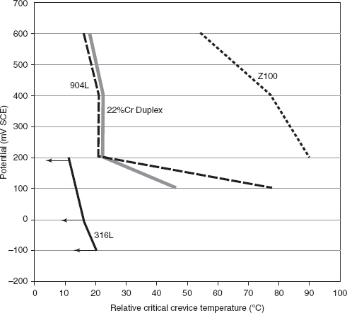
FIGURE 3 Relative crevice critical temperatures of some stainless steels in seawater as a function of potential. SOURCE: Byrne et al., 2009. Previously published proceedings of the IDA World Congress on Desalination and Water Reuse in Dubai, UA - October 2009.
expected to have a relatively high sulfate-to-chloride ratio, it is possible that pitting will be less of a problem than it would be without the sulfate. This further demonstrates the desirability of conducting corrosion tests with the process fluid.
There are ASTM International and NACE [National Association of Corrosion Engineers] International standard tests for evaluating the resistance of alloys to pitting and crevice corrosion. For example, ASTM G48 (ASTM, 2009a) refers to test methods and procedures to determine pitting and crevice corrosion resistance of stainless steels and related alloys when they are exposed to oxidizing chloride environments. These tests are designed to cause localized corrosion more quickly than in most natural environments. Consequently, corrosion damage during testing will generally be more severe than in a natural environment for a similar period of time. Procedures are described and identified for determining critical pitting temperatures for stainless steels and for nickel-base alloys as well as for developing a relative ranking of the susceptibility of such alloys to crevice and pitting corrosion. Test results can be used to rank the resistance of alloys to pitting and crevice corrosion. ASTM G48 uses ferric chloride solutions as the test environment because this test chemistry is related to the chemistry in pit or crevice sites on ferrous alloys in chloride-bearing environments. Relative alloy performance in these tests has been correlated to performance in certain real
environments, such as natural, ambient-temperature, seawater, and strongly oxidizing, low-pH, chloride-containing environments.
Cyclic polarization is another accelerated test that may be used to assess the relative susceptibility of a series of alloys to pitting and crevice corrosion. ASTM Standard G61 (ASTM, 2009b) describes this approach. In this test, one could use as the test environment a synthetic process fluid that chemically matches the composition of the expected process fluid. In either approach, the objective would be to produce an accelerated evaluation of the susceptibility of alloys to pitting and crevice corrosion.
In response to corrosion concerns in the BGCAPP design, Battelle prepared a white paper on the corrosion of 316 stainless steel in the RO unit (Battelle, 2011). In this paper, type 316L is recommended for the filters and pumps, and duplex 2205 stainless steel is recommended for the piping throughout the process. The PMACWA found that 316L pumps are not available. (Note: 316 is actually a wrought alloy designation. The cast alloy designations are CF3M and CF8M for 316L and 316, respectively.) The reason for using the “L” grade is to avoid weld heat-affected zone corrosion, and so the use of cast pumps made of the equivalent to regular grade 316 stainless steel (CF8M) may be appropriate since there would be little or no welding on the pump body. The overall corrosion resistance of CF3M and CF8M would be expected to be similar. This assumes that subsequent testing confirms the suitability of type 316 alloy for this application.
Finding. If the testing recommended in this report is not conducted, the use of a duplex alloy such as 2205 for the piping lines may be appropriate, based on the preceding discussion.
Stress Corrosion Cracking
Stress corrosion cracking occurs when a susceptible alloy is exposed to an environment that is capable of initiating cracking events when sufficient operational tensile stresses are present. Thus, knowledge of the anticipated stress field in any component of interest is paramount, as is the chemistry of the service environment.
The 60°C (140°F) threshold for SCC mentioned in the attachments to the Battelle white paper (Battelle, 2011) is not completely borne out in practice. Experience with SCC of austenitic stainless steels (e.g., 304 and 316) suggests that there is little danger of cracking below about 45°C (113°F), as shown in Figure 4. This temperature, from Freedman et al. (2004), is close to the planned operating temperature of the BGCAPP RO unit. While the risk may be small, it would be prudent to confirm the absence of stress corrosion cracking tendencies with laboratory tests.
The slow strain rate test, ASTM G129, is used to test resistance to SCC in metallic materials, in a variety of environmental conditions, in an accelerated manner (ASTM, 2006a). It is used for the rapid screening and/or comparative evaluation of the resistance of materials to SCC in relation to environmental, processing, and metallurgical variables. ASTM G129 has been used to evaluate materials, heat treatments, chemical constituents in the environment, temperature, and chemical inhibitors. Slow strain rate testing can be used to evaluate a wide variety of metallic materials in environments that could cause SCC, covering a broad range of temperatures and pressures. Since this is an accelerated test, the results are not meant to necessarily indicate the performance of
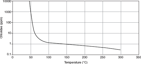
FIGURE 4 Stress corrosion cracking limits for 304/316 stainless steels in a variety of mixed process waters containing chlorides. SOURCE: Freedman et al., 2004. © MATERIALS TECHNOLOGY INSTITUTE, INC. [2004]. Reprinted with permission of the Copyright Owner.
materials in a given operational environment. Rather, it provides a basis for material screening. It can be used to detect environmental interactions with materials. It can also be used to conduct a comparative evaluation of the effects of various metallurgical and environmental variables on the sensitivity of materials to environmental cracking problems. Constant-load or -strain SCC tests should also be conducted in environments that simulate the expected operational environment. If possible, actual operational experience should be gained so that a correlation between the test results and anticipated operational performance can be developed. ASTM G36 is an accelerated test for SCC of various stainless alloys; it uses boiling magnesium chloride as a test environment, but could be modified to serve as a guide to constant-load testing in a simulated service environment (ASTM, 2006b). ISO [International Organization for Standardization] Standard 7539 is a comprehensive stress corrosion testing standard that includes constant-load as well as slow strain rate testing details (ISO, 1989).
Saithala et al. (2010) found that the resistance to SCC increased as the PRE number increased, but for all of the alloys tested there was a critical cracking potential above which SCC occurred. This result suggests that using an alloy with a higher PRE number than that of 316L stainless steel would be beneficial if it is determined that type 316L would be risky in this application.10
MOC Findings and Recommendations
Finding. Given that the committee is not aware of any other water recovery systems that treat effluents similar to those expected from the BGCAPP supercritical water oxidation system, the bases for the present material selections are not well supported.
Finding. Given the limited information available, it cannot be determined with confidence whether the materials of construction currently selected will be adequate for their planned applications. It is possible that the corrosion resistance of type 316L stainless steel may be adequate for the piping, filters, and pumps (CF3M or CF8M) in
_____________________
10See footnote 9.
this system for the planned operational lifetime of the system. However, it is also possible that it would be inadequate. Laboratory testing would reduce this uncertainty.
Finding. Testing at elevated temperatures may be required for the piping between the supercritical water oxidation reactor and the first pretreatment unit.
Recommendation. Laboratory qualification testing should be conducted to validate the selection of materials from a corrosion engineering perspective. The modes of corrosion that should be investigated are pitting, crevice corrosion, and stress corrosion cracking (SCC). Accelerated potentiodynamic polarization testing is a useful approach to evaluation of pitting and crevice corrosion. With the knowledge of the stress state anticipated on relevant components, SCC testing can be pursued. The slow strain rate test is recommended for evaluating SCC. These corrosion tests should be conducted in a chemical environment similar to that expected in the supercritical water oxidation effluents and the reverse osmosis reject. Candidate alloys for evaluation include type 316 stainless steel, a duplex alloy such as 2205, a super duplex alloy, and perhaps a super austenitic stainless steel.
Recommendation. Unless the corrosion testing recommended in this report is performed, to be conservative at the least an alloy such as 2205 SS should be used where appropriate.
REFERENCES
Arnvig, P-E., B. Leffler, E. Alfonsson, and A. Brorson. 1996. Machinability, corrosion resistance and weldability of an inclusion modified 2205 duplex stainless steel. acom 2-1996. Available at http://www.avestapolarit.com/upload/documents/technical/acom/Acom96_2a.PDF. Accessed November 2, 2011.
ASTM (ASTM International). 2006a. Standard Practice for Slow Strain Rate Testing to Evaluate the Susceptibility of Metallic Materials to Environmentally Assisted Cracking, ASTM G129-00(2006). West Conshohocken, Pa.: ASTM International.
ASTM. 2006b. Standard Practice for Evaluating Stress-Corrosion-Cracking Resistance of Metals and Alloys in a Boiling Magnesium Chloride Solution, ASTM G36-94(2006). West Conshohocken, Pa.: ASTM International.
ASTM. 2009a. Standard Test Methods for Pitting and Crevice Corrosion Resistance of Stainless Steels and Related Alloys by Use of Ferric Chloride Solution, ASTM G4803(2009). West Conshohocken, Pa.: ASTM International.
ASTM. 2009b. Standard Test Method for Conducting Cyclic Potentiodynamic Polarization Measurements for Localized Corrosion Susceptibility of Iron-, Nickel-, or Cobalt-Based Alloys, ASTM G61-86(2009). West Conshohocken, Pa.: ASTM International.
Avista (Avista Technologies, Inc.). 2005. Compatibility Study: Vitec 3000 Versus Roquest 3000, May. San Marcos, Calif.: Avista Technologies, Inc.
Battelle. 2011. WP-112: Corrosion of 316 Stainless Steel in Reverse Osmosis Reject Water Lines, Rev. B, February 22. Richmond, Ky.: Blue Grass Chemical Agent Destruction Pilot Plant Project.
Bhattacharyya, D., W.C. Mangum, and M.E. Williams. 1999. Reverse osmosis. Pp. 1757-1759 in Kirk-Othmer Encyclopedia of Chemical Technology, 4th Ed. J.I. Kroschwitz, ed. New York, N.Y.: Wiley.
Bechtel. 2007. Mechanical Systems Data Sheet: Reverse Osmosis Unit, Rev. E, October 15. Richmond, Ky.: Blue Grass Chemical Agent Destruction Pilot Plant Project.
BPBG (Bechtel Parsons Blue Grass). 2005. Technical Risk Reduction Project (TRRP) 07 and 09 Report on Supercritical Water Oxidation Blended Feed Performance Tests, Rev. 0, May 5. Richmond, Ky.: Blue Grass Chemical Agent Destruction Pilot Plant Project.
BPBG. 2006. Trend Notice, SPB Deletion of Clarifier and Clear Well Tank, Trend Number TN-24915-06-00126, September 13. Richmond, Ky.: Blue Grass Chemical Agent Destruction Pilot Plant Project.
BPBG. 2007. SCWO Building Water Recovery—R.O. Unit Process Flow Diagram, Rev. 6, Sheet 1/2, October 2. Richmond, Ky.: Blue Grass Chemical Agent Destruction Pilot Plant Project.
BPBG. 2009. System Design Description for Water Recovery System, Rev. 2, July 16. Richmond, Ky.: Blue Grass Chemical Agent Destruction Pilot Plant Project.
BPBG. 2010. SCWO Building Water Recovery—Tanks Process Flow Diagram, Rev. 8, Sheet 2 of 2, June 11. Richmond, Ky.: Blue Grass Chemical Agent Destruction Pilot Plant Project.
Brehant, A., V. Bonnelye, and M. Perez. 2002. Comparison of MF/UF pretreatment with conventional filtration prior to RO membranes for surface seawater desalination. Desalination 144(1-3):353-360.
Byrne, G., R. Francis, G. Warburton, and J. Wilson. 2009. Electrochemical potential and the corrosion resistance of stainless steels in SWRO applications. Paper presented at the International Desalination Association World Congress 2009, October, Dubai, UAE. Available at http://www.rolledalloys.com/technical-resources/corrosionresistant-alloys. Accessed November 2, 2011.
Crum, J.R., and L.E. Shoemaker. 2009. Defining acceptable environmental ranges and welding procedures for corrosion resistant alloys, Paper 09381. NACE International Corrosion 2009 Conference Proceedings. Houston, Tex.: NACE International.
Francis, R., G. Byrne, and G. Warburton. 2011. The corrosion of superduplex stainless steel in different types of seawater, Paper 11351. NACE International Corrosion 2011 Conference Proceedings. Houston, Tex.: NACE International.
Freedman, A.J., A.S. Krisher, and D. Steinmeyer. 2004. Guidelines for Troubleshooting Water Cooled Heat Exchangers. St. Louis, Mo.: Materials Technology Institute.
Ho, W.S.W., and K.K. Sirkar. 1992. Membrane Handbook. New York. N.Y.: Van Nostrand Reinhold.
ISO (International Organization for Standardization). 1989. Corrosion of Metals and Alloys—Stress Corrosion Testing—Part 4: Preparation and Use of Uniaxially Loaded Tension Specimens, ISO 7539-4:1989. Geneva, Switzerland: ISO.
Li, N.N., A.G. Fane, W.S.W. Ho, and T. Matsuura. 2008. Advanced Membrane Technology and Applications. Hoboken, N.J.: Wiley.
Malik, A.U., M. Mobin, F. Al-Muaili, and S. Al-Fozan. 2011. Corrosion behavior of duplex stainless steels in Arabian seawater, Paper 11171. NACE International Corrosion 2011 Conference Proceedings. Houston, Tex.: NACE International.
NRC (National Research Council). 2005. Interim Design Assessment for the Blue Grass Chemical Agent Destruction Pilot Plant. Washington, D.C.: The National Academies Press.
Pendergast, M.T.M., and E.M.V. Hoek. 2011. A review of water treatment membrane nanotechnologies. Energy and Environmental Science 6(4):1946-1971.
Pohjanne, P., A. Sarpola, L. Carpen, M. Riihimaki, P. Kinnunen, T. Hakkarainen, and J. Ramo. 2007. Stainless steel pitting in chloridesulfate solutions: The role of cations, Paper 07198. NACE International Corrosion 2007 Conference Proceedings. Houston, Tex.: NACE International.
Saithala, J.R., S. McCoy, J.D. Atkinson, and H.S. Ubhi. 2010. Critical stress corrosion cracking potentials of stainless steels in dilute chloride solutions, Paper 10287. NACE International Corrosion 2010 Conference Proceedings. Houston, Tex.: NACE International.
Siavash, M.S., T. Mohamamdi, and M.K. Moghadam. 2001. Chemical cleaning of reverse osmosis membranes. Desalination 134(1):77-82.
Wilf, M., and M.K. Schierach. 2001. Improved performance and cost reduction of RO seawater systems using UF pretreatment. Desalination 135(1-3):61-68.
Williams, M.E. 2003. A Brief Review of Reverse Osmosis Membrane Technology. Available at http://www.wescinc.com/files/RO_Review.pdf. Accessed November 23, 2011.


