
2
Air Force EELV-Class Launch Requirements and Approaches
This chapter provides summary descriptions of the criteria and assumptions formulating the baseline reusable booster system (RBS) program, including overall requirements, programmatic and technical approaches, summary results of the business case analysis, and a brief discussion of other, recent and relevant launch programs.
Evaluation of alternative launch and upper stage options for Evolved Expendable Launch Vehicle (EELV)-class missions is the focus of this report, and nominal EELV mission frequencies and payload masses were briefly cited in Chapter 1. Assured access to space for national security payloads is the overarching requirement for EELV-class missions and has formidable programmatic and technical implications. EELV launches will be required during the development and phased introduction (estimated at approximately 5 years) of any new launch capability,1 which has significant budgetary consequences. Air Force policy is to provide launches for the full set of missions described in Chapter 1; this calls for both equatorial and polar launches and a large range of lift capabilities. In addition, the Air Force requires that the high EELV reliability be maintained (it has resulted in more than 30 launches without a single failure) and significant reductions in costs in relation to EELV costs for the mission set of Chapter 1.
The Air Force has specified a launch-on-schedule approach for the EELV mission set, and that has mitigated vehicle, pad, and operations requirements for fast turnaround. A recently released Air Force presolicitation2 (the Orbital/Sub-Orbital Program) calls for small and medium spacelift capabilities, of up to 20,000 lb to low Earth orbit (LEO) equivalent, which may address the critical area of “responsive” Air Force launch. In addition, the Air Force has expressed concern about the health and future of the U.S. launcher industrial base, indicated a desire for competition for future launch services, and signified its openness to either reusable or new expendable launchers to meet its global requirements.3 Different RBS schedules are under consideration, but the nominal phaseout of EELVs is estimated to be in the 2031 time frame. No overall procurement strategy has been defined, and issues
_____________
1 Air Force Space and Missile Systems Center (AFSMC), “Reusable Booster System Costing, SMC Developmental Planning,” presentation to the Committee for the Reusable Booster System: Review and Assessment, February 15, 2012. Approved for Public Release.
2 AFSMC, Presolicitation FA8818-11-R-0026, Orbital/Suborbital Small & Medium Lift Program (OSP-3), Space Development and Test Directorate, Last modification February 15, 2012.
3 Air Force Space Command (AFSPC), “AFSPC Operational Requirements for Launch,” presentation to the Committee for the Reusable Booster System: Review and Assessment, March 28, 2012. Distribution Statement: No Restrictions.
such as the potential for competition and the relationship of RBS to the launch needs of other U.S. space sectors are open at this time.
The Space and Missile Systems Center (SMC/XR),4 the Air Force Research Laboratory (AFRL),5 and the Aerospace Corporation6 extensively evaluated options to meet the Air Force, EELV-class mission requirements, and these evaluations will be augmented by newly commissioned economic analyses by industry. The RBS was judged to offer the best potential for both low-risk development and recurring cost reductions, relative to EELVs, of 50 to 67 percent.7
The baseline flight vehicles for the RBS concept,8 which are shown in Figure 2.1, consist of a reusable booster demonstrator (RBD), a medium-lift launch vehicle consisting of a reusable booster and an expendable upper stage, and a heavy-lift configuration consisting of two reusable boosters and expendable upper stages. All RBS variations are envisioned to be unmanned and to operate autonomously. As discussed in Chapter 1, the RBS concept involves a reusable first stage (or two first stages in the heavy-lift variant shown in Figure 2.1), which separates from one or more expendable upper stages at velocities between Mach 3.5 to 7 and then returns to the launch base by a “rocketback” maneuver using one of the first-stage rocket engines. Importantly, the staging velocities and altitudes were selected to optimize overall costs and risks rather than to optimize staging to maximize delivered payload. The main potential benefits of the RBS are said to include cost reductions via recovery of the expensive first stage, the corresponding reduction in expendable hardware, and more efficient ground operations.9
The RBD vehicle is a proposed midscale demonstration vehicle that would be developed as an intermediate step between today’s research program and a full-scale RBS system. The RBD would use a single NK-33 LO2/RP oxygen-rich, staged-combustion (ORSC) rocket engine to power the reusable first stage. The RBD would initially be used to demonstrate significant aspects of the rocketback return-to-launch-site (RTLS) maneuver, including expendable stage separation. Using a Castor 30 motor and a Star 63 solid motor to power the upper stages as a small expendable stage (SES), the RBD would be capable of launching small satellites to LEO.
The medium-lift RBS configuration (middle configuration in Figure 2.1) consists of a full-scale reusable booster and a large expendable stage (LES). The baseline configuration for the reusable booster is powered by five AJ-26 rocket engines; the AJ-26 is an “Americanized” version of the Russian NK-33 rocket engine. These engines operate using liquid oxygen and hydrocarbon fuels (e.g., RP-1) using an ORSC cycle. The baseline LES is powered by one RS-25E rocket engine using liquid oxygen and liquid hydrogen propellants. This RS-25E is an expendable version of a space shuttle main engine (SSME) being developed by NASA for use in its Space Launch System.
The heavy-lift RBS configuration (right configuration in Figure 2.1) consists of two reusable booster systems, one LES, and a solid-rocket-propelled third stage. This configuration, which would only be used by the Air Force for the largest national security payloads, would result in the additional complexity of having two reusable boosters separate simultaneously and execute their RTLS maneuver in the same airspace.
In addition to the proposed vehicles shown in Figure 2.1, AFRL is actively working on technologies to support the RBS concept. These include technologies for hydrocarbon-fueled boosters, integrated vehicle health management (IVHM), and adaptive guidance and control (AG&C). AFRL is also funding development of a small-scale demonstrator vehicle called Pathfinder, which aims to investigate the rocketback RTLS maneuver, including propellant management strategies, in a series of early flight tests. While the AFRL-funded activities are not part of the baseline RBS development program, these efforts serve to provide critical information leading into the larger-scale RBS development activities.
_____________
4 AFSMC, “Spacelift Development Planning,” presentation to the Committee for the Reusable Booster System: Review and Assessment, February 15, 2012. Approved for Public Release.
5 Air Force Research Laboratory (AFRL), “AFRL Portfolio: Responsiveness & Reusable Boost System (RBS),” presentation to the Committee for the Reusable Booster System: Review and Assessment, February 17, 2012. Distribution A–Approved for Public Release.
6 AFSMC, “Reusable Booster System Costing, SMC Developmental Planning,” 2012. Approved for Public Release.
7 AFSMC, “Reusable Booster System Costing, SMC Developmental Planning,” 2012; AFSMC, “Spacelift Development Planning,” 2012; AFRL, “AFRL Portfolio: Responsiveness & Reusable Boost System (RBS),” presentation to the Committee for the Reusable Booster System: Review and Assessment, February 17, 2012. Distribution A–Approved for Public Release.
8 AFSMC, “Reusable Booster System Costing, SMC Developmental Planning,” 2012. Approved for Public Release.
9 K.R. Hampsten and R.A. Hickman, Next Generation Air Force Spacelift, AIAA 2010-8723, paper presented at the AIAA Space 2010 Conference and Exposition, Anaheim, Calif., August 30-September 2, 2010. This meeting was unrestricted and open to the public.
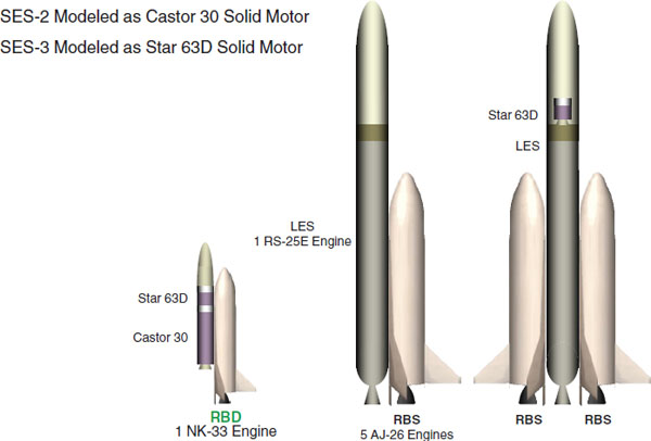
FIGURE 2.1 Reusable booster system (RBS) baseline vehicles. Note that the RBS launching of Evolved Expendable Launch Vehicle heavy payloads requires the added complexity of parallel staging of the first stage boosters. SOURCE: Air Force Space and Missile Systems Center, “Reusable Booster System Costing, SMC Developmental Planning,” presentation to the committee, February 15, 2012. Approved for Public Release.
2.2 RBS SCHEDULE AND PROJECTED COSTS SUMMARIES
The costs and schedules of several RBS program scenarios were evaluated by the Air Force and the Aerospace Corporation.10 (Detailed evaluations of the cost estimates are provided in Chapter 4.) In addition to the AFRL-funded small-scale Pathfinder, the flight vehicles included in costs for the baseline scenario were an RBD and operational vehicles with one and two booster stages. The baseline RBS architecture included two Y vehicles, which are preproduction, full-scale models with the same mass properties and dynamics of the operational RBS vehicles, and which are planned to be converted into operational RBSs after being tested.11
Illustrations of the estimated annual recurring costs for the EELV and baseline RBS program are shown in Figure 2.2. For the baseline architecture, RBS annual recurring costs were estimated (Figure 2.3) to be about 47 percent of those for EELVs; this was the net result of estimated reductions in operation and production costs, respectively, of ~60 and 36 percent.12 A recommendation of the cost study was to fly Pathfinder and RBD vehicles to validate technical approaches and improve estimates of costs and operations.13 Key technical issues and associated schedules and costs are evaluated in Chapters 3 and 4, respectively.
_____________
10 AFSMC, “Reusable Booster System Costing, SMC Developmental Planning,” 2012. Approved for Public Release.
11 AFSMC, “Reusable Booster System Costing, SMC Developmental Planning,” 2012. Approved for Public Release.
12 AFSMC, “Reusable Booster System Costing, SMC Developmental Planning,” 2012. Approved for Public Release.
13 AFSMC, “Reusable Booster System Costing, SMC Developmental Planning,” 2012. Approved for Public Release.
FIGURE 2.2 Evolved Expendable Launch Vehicle (EELV) and reusable booster system (RBS) relative annual recurring cost based on Air Force Space and Missile Systems Center cost estimates. Note that a RBS cost reduction is based on reducing the cost of both expendable hardware and operations. SOURCE: Air Force Space & Missile Systems Center, “Reusable Booster System Costing, SMC Developmental Planning” presentation to the committee, February 15, 2012. Approved for Public Release.
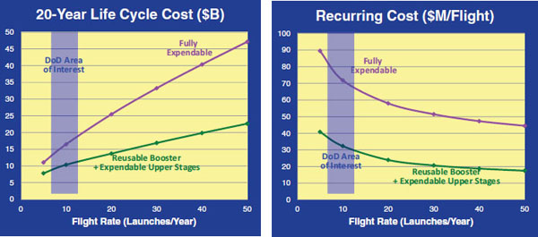
FIGURE 2.3 Comparison of the vehicle life cycle and recurring cost. For the Air Force projected launch rate of 8 to 12 per year, the reusable booster system recurring costs projected by the Air Force Space and Missile Systems Center are approximately $40 million less per launch than the costs with expendable launchers. SOURCE: Air Force Research Laboratory, SMC Development Planning Directorate, “Spacelift Development Planning,” presentation to the committee, February 17, 2012.
Several RBS program scenarios were evaluated by the Air Force and the Aerospace Corporation to assess the life-cycle cost (LCC) and development schedules of RBS options for EELV-class missions.14 The flight vehicles included in cost models for the baseline scenario were a RBD and operational vehicles with one or two reusable boosters. (An X vehicle, which would be much closer in design to the operational vehicles and was estimated to cost about $400 million and require 6 years to build and fully test,15 was not included in baseline cost estimates.) The baseline RBS architecture does include two Y vehicles.
Figure 2.3 shows Air Force estimates of 20-year LCC and recurring launch cost (RLC) of the (1) fully expendable, (2) fully reusable, and (3) RBS launcher options,16 and it is seen that the RBS was projected to provide large LCC and RLC benefits for flight rates from 5 to 50 launches per year. Risks are to be minimized by (1) selection of a staging velocity that subjects the first stage to relatively benign environments, which is intended to mitigate operational requirements and costs and (2) the low sensitivity of launcher performance to first-stage dry mass, which, relative to expendables, will increase to provide for reusability. The RBS does, of course, involve risks associated with new concepts. These include risks associated with the rocketback maneuver, staging of asymmetric or parallel vehicles, first- and second-stage hardware developments, additional operations, achievement of desired operational efficiencies, and projected costs.
2.3 RBS TECHNICAL PROGRAM SUMMARIES
This section and those that follow it will provide brief descriptions of major technical elements of the baseline RBS program, including flight operational vehicles, research and development (R&D) flight vehicles, and the supporting ground R&D efforts. The descriptions below reflect inputs provided to the committee up to May 2012. RBS evaluations are ongoing, and approaches continue to evolve.
The flight vehicles planned17 in the baseline RBS program are shown in Figure 2.1. The baseline program plan would conduct subscale flight tests with two different vehicles to validate the procedure prior to full development of operational systems. Additional details on the ongoing R&D program18 in support of RBS development are described in Chapter 3.
2.3.1 RBS Flight Vehicles, Operations, and Infrastructure
2.3.1.1 Flight Trajectories
The Air Force analyses19 suggest that mission costs, reliabilities, and performances are optimized by use of a RTLS concept for the first stage with expendable upper stages. Options for RTLS included glideback, rocketback, and jetback. Rocketback was selected as the preferred approach20 for multiple reasons, including the requirement for very large upper stages with glideback and the need for an additional propulsion system with jetback.
_____________
14 AFSMC, “Reusable Booster System Costing, SMC Developmental Planning,” 2012. Approved for Public Release.
15 AFRL, “AFRL Portfolio: Responsiveness & Reusable Boost System (RBS),” February 17, 2012. Distribution A–Approved for Public Release.
16 K.R. Hampsten and R.A. Hickman, Next Generation Air Force Spacelift, AIAA 2010-8723, paper presented at the AIAA Space 2010 Conference and Exposition, Anaheim, Calif., August 30-September 2, 2010. This meeting was unrestricted and open to the public.
17 AFSMC, “Reusable Booster System Costing, SMC Developmental Planning,” 2012. Approved for Public Release.
18 U.S. Government Accountability Office, Evolved Expendable Launch Vehicles, GAO-11-641, U.S. GAO, Washington, D.C., September 2011.
19 AFSMC, “Spacelift Development Planning,” 2012; K.R. Hampsten and R.A. Hickman, Next Generation Air Force Spacelift, AIAA 2010-8723, paper presented at the AIAA Space 2010 Conference and Exposition, Anaheim, Calif., August 30-September 2, 2010. Approved for Public Release.
20 AFRL, “AFRL Portfolio: Responsiveness & Reusable Boost System (RBS),” 2012 Distribution A: Approved for Public Release; S.J. Edwards, D.N. Mavris, R. Douglas, and B. Hellman, Reusable Booster Sizing Sensitivities and Flight Envelope Identification Using Response Surface Methods, AIAA 2011-7127, paper presented at the AIAA Space 2011 Conference and Exposition, Long Beach, Calif., September 27-29, 2011. This meeting was unrestricted and open to the public.
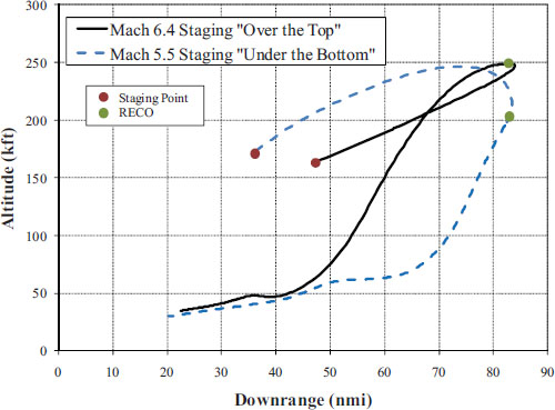
FIGURE 2.4 Typical rocketback return-to-launch-site maneuvers showing staging at Mach 5.5 and 6.4 at altitudes of approximately 160,000 ft. with rocket-engine cut-off occurring at altitudes of 200,000 and 250,000 ft. The reusable booster returns unpowered from its maximum downrange position of approximately 83 nmi. SOURCE: B.M. Hellman, A. Ngo, and J. Wallace, “Technical Challenges for an Integrated Reusable Booster System Flight Demonstrator,” AIAA-2010-8668 in AIAA SPACE 2010 Conference and Exposition, AIAA, Reston, Va. This meeting was unrestricted and open to the public.
Typical RBS trajectories using the rocketback RTLS maneuver are shown in Figure 2.4.21 These sample trajectories illustrate staging at Mach 5.5 and 6.4 conditions at an altitude of approximately 160,000 ft. Two variations of an in-plane rocketback RTLS maneuver are shown. For both trajectories, one or more of the rocket engines continues to fire after staging and the vehicle maneuvers so that the engine thrust cancels the downrange velocity and provides sufficient momentum for an unpowered return segment of the trajectory profile. As seen for this example trajectory, the rocket engine cut-off (RECO) occurs 83 nmi downrange at altitudes between 200,000 and 250,000 ft.
In general, typical staging velocities are between Mach 3.5 and 7 as lower staging velocities tend to require very large upper stages, and higher staging velocities subject the first stage to atmospheric heating and structural dynamic environments that demand increased thermal protection, more stringent structural requirements, and higher operating costs.
Figure 2.5 presents a typical trade-off result22 showing the expended dry weight as a function of the staging velocity. As will be discussed in Chapter 4, parametric cost models are heavily driven by dry mass, so total dry mass can be viewed as an early indicator of cost. Staging is complex and sensitive to a wide range of coupled trajectory and vehicle design alternatives.23 Staging is also the second most common cause of launch failures,24
_____________
21 B.M. Hellman, A. Ngo, and J. Wallace, “Technical Challenges for an Integrated Reusable Booster System Flight Demonstrator,” AIAA-2010-8668, August 30-September 2, 2010, Anaheim, Calif., 2010. This meeting was unrestricted and open to the public.
22 K.R. Hampsten and R.A. Hickman, Next Generation Air Force Spacelift, AIAA 2010-8723, paper presented at the AIAA Space 2010 Conference and Exposition, Anaheim, Calif., August 30-September 2, 2010. This meeting was unrestricted and open to the public.
23 D.G. Luchinsky et al., Physics-based modeling for stage separation recontact, Journal of Spacecraft and Rockets 49(2):231-242, 2012.
24 Futron Corporation, “Design Reliability Comparison for SpaceX Falcon Vehicles,” November 2004.
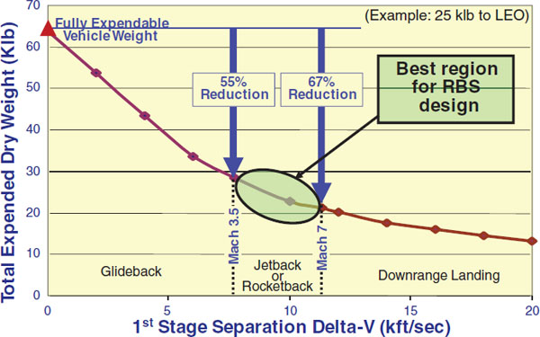
FIGURE 2.5 Expended dry weight of upper stage versus separation delta velocity. SOURCE: Air Force Research Laboratory, SMC Development Planning Directorate, “Spacelift Development Planning,” presentation to the committee, February 17, 2012. Approved for Public Release.
and staging of such large, asymmetrical systems requires resolution of issues such as RBS staging implementation approaches, booster-upper stage attachment points, and subsequent loads. These results show that at lower staging velocities the expendable upper stage is very large, which drives up recurring costs. However, higher separation velocities drive requirements for thermal protection on the reusable first stage, which increases stage mass and significantly degrades ground operational efficiencies.
After staging, the expendable upper stages deliver the payloads to appropriate orbits. The first stage is subsequently maneuvered so that a single main engine can be throttled back to provide accelerations appropriate for propellant management, to eliminate the downrange velocity, and then to provide sufficient velocity for the RTLS. The maneuver requires angles of attack approaching 180 degrees, where existing computational models have not been validated and which cannot be suitably simulated in ground wind tunnel tests.25 Shutdown of some engines and deep throttling of at least one engine is required. Additional issues such as propellant management, aerodynamic interactions, plume loads, and vehicle stability and control will have to be successfully addressed for the proposed RTLS maneuver. Finally, the main engine is shut down and the vehicle glides back for a horizontal landing at the launch site. Significant confidence in the final, glideback phase has been gained via similar experiences with vehicles such as the space shuttle and the X-37 and X-40. The rocketback maneuver has never been employed by launch vehicles and is considered one of the high-risk elements of the proposed RBS program.
_____________
25 AFRL, “AFRL Portfolio: Responsiveness & Reusable Boost System (RBS),” 2012. Distribution A–Approved for Public Release.
2.3.1.2 First-Stage Vehicle
The RBS first and upper stages were shown in Figure 2.1. To minimize development and production costs, only one first-stage configuration is planned and one vehicle will be sufficient for all but the most energetic EELV-class missions, which instead will use two opposing first stages attached to a single upper stage. A representative first stage in the baseline concept is blunt nosed, has double delta wings, is approximately 108 ft long by17 ft in diameter, and holds nearly 900,000 lb of LO2/HC propellants.26 These propellants were selected over LO2/LH2 to reduce (1) overall operations times and costs and (2) vehicle dry masses and volumes. LO2/LCH4 also was evaluated as a first-stage propellant for staged combustion engines and was found to provide mission-level performance nearly identical to that with more mature LO2/HC engines but with higher vehicle dry masses and projected costs.27
An ORSC engine cycle was selected over the fuel-rich, gas generator cycle for several reasons, including high performance and a large reduction in fuel coking, which introduces operational inefficiencies and reusability concerns. ORSC engines have been built and qualified in Russia and China and are under study or in development in Europe, India, and South Korea.28 The Russian-built RD-180 ORSC engine has been successfully used on the Atlas III and V vehicles,29 and the Russian-built NK-33 is planned for use in the near term on the first stage of the Antares launchers of Orbital Sciences Corporation.30 Russian-produced ORSC engines are also planned for use in early RBS program efforts such as the RBD vehicle,31 with the NK-33 used as the baseline. These NK-33 engines have been acquired by Aerojet and upgraded to include modern diagnostics and controls. The baseline operational flight vehicle concept now features the use of five AJ-26 engines,32 which are “Americanized” versions of the NK-33 cited above. The AJ-26 engine, which would be fully produced in the United States, has a sea level thrust and specific impulse, respectively, of 338,000 lbf and 297 sec. No ORSC engine has been developed in the United States, but efforts evaluating production of U.S.-built versions of both RD-180 and NK-33-class engines have been ongoing for about a decade.33 A reusable, U.S.-produced ORSC LO2/HC engine is one of the main development efforts in the RBS program;34 the technical challenges and issues are discussed in depth in Chapter 3.
Metallic structures and tanks are presently baselined for the RBS first-stage vehicle; however, the increasing pressure for performance is driving R&D35 to examine the possible use of composites for the RBS primary structure and improved ancillary subsystems such as thermal, power, reaction control, and actuation.
2.3.1.3 Upper Stage(s)
As shown in Figure 2.1, a single LO2/LH2 LES design is planned for the EELV-class missions; except that for the most energetic EELV-class mission a solid Star 63D type motor is added as a third stage. The baseline LES is about 130 ft long and 15 ft in diameter; it has a dry weight of ~38,800 lb, and carries more than 340,000 lb of propellant.36 For reference, the LES propellant load is approximately 1.4 and 0.76 times the amounts carried in,
_____________
26 AFSMC, “Reusable Booster System Costing, SMC Developmental Planning,” 2012. Approved for Public Release.
27 Futron Corporation, “Design Reliability Comparison for SpaceX Falcon Vehicles,” November 2004.
28 Pratt and Whitney Rocketdyne, “Reusable Hydrocarbon Rocket Engine Maturity for USAF RBS,” presentation to the Committee for the Reusable Booster System: Review and Assessment, February 16, 2012. Approved for Public Release; Aerojet Corporation, “Reusability and Hydrocarbon Rocket Engines-Relevant US Industry Experience,” presentation to the Committee for the Reusable Booster System: Review and Assessment, February 16, 2012. Approved for Public Release.
29 Pratt and Whitney Rocketdyne, “Reusable Hydrocarbon Rocket Engine Maturity for USAF RBS,” 2012. Approved for Public Release.
30 Aerojet Corporation, “Reusability and Hydrocarbon Rocket Engines-Relevant US Industry Experience,” 2012. Approved for Public Release.
31 AFSMC, “Reusable Booster System Costing, SMC Developmental Planning,” 2012. Approved for Public Release.
32 AFSMC, “Reusable Booster System Costing, SMC Developmental Planning,” 2012. Approved for Public Release.
33 Pratt and Whitney Rocketdyne, “Reusable Hydrocarbon Rocket Engine Maturity for USAF RBS,” 2012; Aerojet Corporation, “Reusability and Hydrocarbon Rocket Engines-Relevant US Industry Experience,” 2012. Approved for Public Release.
34 AFRL, “Hydrocarbon Boost Technology for Future Spacelift,” presentation to the Committee for the Reusable Booster System: Review and Assessment, February 15, 2012. Distribution A–Approved for Public Release.
35 AFRL, “AFRL Portfolio: Responsiveness & Reusable Boost System (RBS),” 2012. Distribution A–Approved for Public Release.
36 AFSMC, “Reusable Booster System Costing, SMC Developmental Planning,” 2012. Approved for Public Release.
respectively, the Saturn SIV-B stage37 and the Delta IV common booster core (CBC).38 A single RS-25E engine, with a sea-level thrust of approximately 420,000 lbf and specific impulse of approximately 350 sec is presently baselined, although options such as the RD-0120 and J-2X are under consideration. The LES is mounted to the first stage by four structural-release attachments, two forward and two aft. Staging is achieved by shutting off all but the center engine of the first stage, throttling it back and starting the RS-25E engine. When the booster and LES thrust levels are such to produce nominally equal accelerations following separation, the LES is released and, once clear of the booster, the RS-25E engine returns to full thrust. The LES fairing is jettisoned when aerodynamic and heating loads allow, and the LES then delivers its payload to the desired orbit.
Except for the size, attachment geometry, and engine, the LES design and system requirements are similar to those for upper stages of EELVs. The propellant tank must react to loads from the side mounting and separation forces, as does the CBC tank, which is similar in size. These LES loads will be different than for the Delta IV-H, but the load paths are similar and the analytic techniques used for the CBC will probably be appropriate. The propellant feed and management subsystems will likely be similar for the LES and CBC (except the LES engine thrust is considerably lower), and engines on both vehicles use single gimbaled engines. The requirements for other hardware elements of the LES, including the fairing, payload separation, thrust vector control, avionics and telemetry, and reaction control subsystems appear very similar to those of operational EELV upper stages. Unlike the EELVs, the first-stage booster will require its own avionics; but the LES software functions will be similar to those for EELV upper stages.
2.3.1.4 Operations
The RBS baseline operations requirement is efficient accommodation of an average of eight launches per year from the Cape Canaveral Air Force Station (CCAFS) and Vandenberg Air Force Base (VAFB). To meet the operations requirement, a fleet of eight RBSs is planned,39 including the two converted Y vehicles, with four each at both CCAFS and VAFB. The baseline assumptions are 10 flights between depot maintenance and 20 flights between RBS engine refurbishments.40 First-stage reusability goals are 20 flights for the main engine and approximately 100 flights for the overall vehicle. As previously mentioned, the EELV-class missions have been designated “launch-on-schedule,”41 so rapid ground reprocessing is not required. During a mission the unpiloted booster will need to be capable of automatically and rapidly assessing its health, identifying degraded or failed subsystems, and taking appropriate corrective actions. These actions include (1) nominal mission completion, (2) sacrifice of the payload with recovery of the first stage, or (3) sacrifice of the booster to enable delivery of the payload. AG&C and IVHM will need to be developed to provide these capabilities.
Following a successful mission, the reusable booster would return and land horizontally at the launch base landing strip. Fluid to be handled should be nonhazardous and nontoxic to avoid operations that require self-contained atmospheric protection ensemble suits, and the booster would be designed to allow for efficient access to and energizing of critical subsystems. In addition to enabling appropriate flight control capabilities, it is desirable that the IVHM be designed to minimize the use of touch labor for ground maintenance.
The LES, payload, and fairing would be processed in parallel with the RBS. LES ground processing is likely to be similar to that being used for EELVs. The final ground operations would consist of mating the integrated LES and payload with the RBS booster, automated system checkout, transport to the launch pad, propellant loading, and launch.
Because an EELV launch-on-schedule assessment has been imposed on a fleet of eight RBS boosters, no operability requirement is generated. Lacking an operability requirement, there is no forcing function to achieve efficient booster reusability. If the Air Force desires this capability with RBS, it needs to define specific operability
_____________
37 See Encyclopedia Astronautica, Saturn IVB (S-IB), available at http://www.astronautix.com/stages/satvbsib.htm.
38 See Space Launch Report, Delta IV Data Sheet, available at http://www.spacelaunchreport.com/delta4.html.
39 K.R. Hampsten and R.A. Hickman, Next Generation Air Force Spacelift, AIAA 2010-8723, paper presented at the AIAA Space 2010 Conference and Exposition, Anaheim, Calif., August 30-September 2, 2010. This meeting was unrestricted and open to the public.
40 AFSMC, “Reusable Booster System Costing, SMC Developmental Planning,” 2012. Approved for Public Release.
41 AFSPC, “AFSPC Operational Requirements for Launch,” 2012. Distribution statement: No restrictions.
requirements, which will drive booster design to enable efficient ground turnaround operations. Further discussion of operability considerations based on lessons learned from the space shuttle is contained in Appendix F.
2.3.1.5 Infrastructure
The baseline RBS concept includes one modified and one new launch pad at CCAFS and one modified launch pad at VAFB.42 The modification of Atlas V launch sites at CCAFS and VAFB was baselined for two of the three RBS launch sites. These existing launch complexes use different Atlas processing techniques as discussed in Section 3.7. Depending on the RBS processing approach(s), the infrastructure modification costs for RBS at these sites could vary considerably. Supporting infrastructure includes a mission control center, launch vehicle processing facilities, solid motor processing/storage facilities, mechanical and electrical ground support equipment (GSE), miscellaneous checkout facilities, and storage facilities. When practical, duplicate facilities based on common designs were assumed.43 Launch complex installation items such as site preparation, utilities, access roads, and activation were also accounted for in the RBS planning. Horizontal or vertical vehicle processing are demonstrated approaches, and selection will depend on trade-offs between facility, GSE, and touch labor costs. Location of vehicle element manufacturing facilities is open but may be an important cost and schedule consideration.
2.3.2 Development Flight Vehicles
In addition to the AFRL-funded RBS Pathfinder, the baseline RBS program includes a reusable booster demonstrator vehicle, the RBD. The objectives and approaches for the Pathfinder and RBD are discussed briefly below.
2.3.2.1 RBS Pathfinder Development Vehicle
The overall objective of the RBS Pathfinder project is to provide timely and cost-effective information on RBS concept of operations, which is traceable to operational flight conditions, including the rocketback turnaround maneuver and RTLS operations. The Pathfinder project is a partnership between AFRL and SMC with an estimated cost of $57 million. Pathfinder would perform vertical takeoffs, horizontal landings, and RTLSs.44 Flight conditions would include angles of attack over ±180 degrees, staging Mach numbers from Mach 3.5 to approximately Mach 7, dynamic pressures up to 100 psf, and rotation rates from 20 to 30 degrees/sec. System-level issues to be addressed include propellant management, especially during the rotation maneuver; main engine throttling; loads on the vehicle; and first validations of AG&C and IVHM approaches. A very wide range of relevant aerodynamic phenomena will be experienced that will provide new and difficult challenges to existing computational models to predict and lead design, development, and flight demonstration phases. Further technical details on Pathfinder dealing with the RTLS maneuver and the mitigation of the risks involved appear in Section 3.3.
Three contractors were selected45 in December 2011 to define requirements and design concepts for the RBS Pathfinder. These contracts are the first phases of a planned four-phase program, now scheduled for completion in late 2016, to build and flight test the RBS Pathfinder.
2.3.2.2 RBD Demonstrator Flight Vehicles
The RBD is a step between the RBS Pathfinder and the operational RBS and is presently less well defined than RBS Pathfinder. Its primary purpose is to demonstrate the rocketback and RTLS maneuvers with a vehicle more closely representing the full-scale RBS booster and to demonstrate rapid ground processing operations for
_____________
42 AFSMC, “Reusable Booster System Costing, SMC Developmental Planning,” 2012. Approved for Public Release.
43 AFSMC, “Reusable Booster System Costing, SMC Developmental Planning,” 2012. Approved for Public Release.
44 AFSMC, “Spacelift Development Planning,” 2012; AFRL, “AFRL Portfolio: Responsiveness & Reusable Boost System (RBS),” 2012. Approved for Public Release.
45 Guy Norris, USAF Paves Way For Reusable Booster Demonstrator, Aviation Week and Space Technology, December 12, 2011, available at http://www.aviationweek.com/Article.aspx?id=/article-xml/AW_12_12_2011_p32-403128.xml.
reflight. (An additional vehicle, the RB-X, was also presented to the committee, but only the RBD was cited as part of the baseline RBS program.46) The RBD is a midscale version of the operational RBS, and the baseline design is a reusable booster with a single NK-33 main engine and side-mounted Castor 30 and Star 63D solid upper-stage engines. The planned flight-test program includes nine suborbital flights and one orbital mission. As mentioned previously, the baseline program would also include two Y vehicles, which serve as the highest-fidelity demonstrators in the program and would be converted to operational use after test program completion.
The AFRL is conducting ground-based R&D in support of key RBS technologies.47 The R&D areas include those shown in Table 2.1.
The AFRL estimated the overall resources required for the RBS ground-based R&D from fiscal year (FY) 2012 through ORSC HC engine completion in FY2020 at about $538 million.48 The level of actual resources presently approved for RBS ground-based R&D was unclear from presentations to the committee.
2.4 ADDITIONAL PROGRAMMATIC CONSIDERATIONS
2.4.1 External Program Considerations
The baseline RBS program indicated a requirement for significant external program support only in the maintenance by NASA of the production line for a LO2/LH2 upper-stage engine (i.e., the RS-25E) for the RBS. That line is associated with NASA’s Space Launch System program and is provided by a U.S. entity that is undergoing downsizing and possible ownership transition. No information was provided to the committee on the consequences of either NASA’s lack of support for RS-25E-class engines or changes in supplier ownership status.
Multiple opportunities do exist, especially for more fundamental aspects of the RBS program, for valuable cooperation between the Air Force RBS and other programs. Areas of potential cooperation include materials, combustion stability, and performance models for ORSC reusable engines; validated models for aerodynamic, thermal, plume, and attachment loads on the RBS; and RBS power, thermal, and other subsystems.
Affordability and industrial base issues were identified by the Air Force as the greatest challenges facing U.S. space launch.49 No information was provided to the committee on how the RBS program would, if successful, affect the overall U.S. industrial base for launch systems and operations. The planned RBS development program, including ground-based R&D and flight vehicle efforts and the significant overlap between the EELV and RBS programs, would warrant significant contractual efforts across a wide industrial base for a sustained period. However, the present RBS Pathfinder program would downselect to a single contractor after completion of the Phase 1 effort described above.50 The number of suppliers for major operational RBS elements is presently unknown, but the available costing data for the baseline RBS program do not assume multiple suppliers of those systems. This suggests that at the conclusion of a successful RBS program, the industrial base for RBS EELV-class missions would resemble that supporting the present EELV program.
_____________
46 AFSMC, “Reusable Booster System Costing, SMC Developmental Planning,” 2012. Approved for Public Release.
47 AFRL, “AFRL Portfolio: Responsiveness & Reusable Boost System (RBS),” 2012. Distribution A–Approved for Public Release.
48 AFRL, “AFRL Portfolio: Responsiveness & Reusable Boost System (RBS),” 2012. Distribution A–Approved for Public Release.
49 AFSPC, “AFSPC Operational Requirements for Launch,” 2012. Distribution Statement: No restrictions.
50 AFRL, “AFRL Portfolio: Responsiveness & Reusable Boost System (RBS),” 2012. Distribution A–Approved for Public Release.
TABLE 2.1 Reusable Booster System (RBS) Ground-Based Research and Development (R&D) Areas
|
RBS Ground R&D Element |
Comment |
|
|
Oxygen-rich, staged-combustion (ORSC), hydrocarbon engine |
Enable U.S.-built, ORSC engine with acceptable performance, life, reliability, and cost. Augmented by long-term industrial efforts. |
|
|
Return to launch site |
Development/validation of models and hardware required for successful RBS flight phases. Wind tunnel tests as appropriate. |
|
|
Autonomous guidance and control |
Advance controls required for RBS flight phases. |
|
|
Integrated vehicle health management |
Integrated with adaptive guidance and control (AG&C) for flight phases and provides benefits for ground operations. |
|
|
Ground operations |
Includes experiments to validate efficient designs and operations, including subsystem maintenance, propellant management, and vehicle integration. |
|
|
Advanced subsystems |
Efforts on structures, power, thermal, and actuation subsystems tailored to RBS requirements. |
|
2.5 RBS AND RECENT REUSABLE VEHICLES
There have been a number of recent programs for reusable launch vehicles (RLVs). The most relevant are the space shuttle, the National AeroSpace Plane (NASP, X-30), Lockheed Martin X-33, and Kistler K-1, and it is of interest to contrast these with the proposed RBS program. In addition, reusable options for the SpaceX Falcon 9 are under consideration. (Other organizations have initiated efforts on reusable concepts but have not built or tested a full-scale concept.) Table 2.2 lists some salient features of the RBS and the RLV programs.
The requirements and approaches for RBS differ in significant respects from those of prior RLVs, and some of the key differences can be seen in Table 2.2. All these RLVs were required to accommodate crew; which imposes demanding requirements on overall vehicle design that can significantly affect mission performance and cost. The upper stages of the RLVs were designed to be recoverable, which implies they must accommodate very stressing reentry environments. Relative to the RBS vehicle approach, this adds complexity and mass to the upper stages and, in practice, increases ground operation requirements and costs. The RBS is the only concept shown in Table 2.2 that proposes an expendable upper stage and a reusable first stage. That approach enables vehicle and mission options to reduce costs relative to traditional performance-optimized approaches. Other important differences include the single-stage-to-orbit approach of NASP and the X-33; the downrange recovery of the space shuttle; and key subsystems such as first-stage propulsion. It is noted that most of the RLV programs were initiated with requirements for elements that had not been demonstrated under flight-type conditions, much as is being proposed for the RBS program. This, in general, led to unanticipated costs. Overall, the differences between the RBS and RLV programs are such that comparisons between them are unlikely to be fully relevant or prudent. Further discussion of the space shuttle, NASP (X-30), and Venturestar (X-33) is contained in Appendix E.
TABLE 2.2 Major Reusable Booster System (RBS)/Reusable Launch Vehicle Features
| Program | Customer | Crewa | Reused Elements | Ascent Concept | Final Orbit | Upper Stage Reuse | Key Elements at TRL<6 at Program Start |
| Space shuttle | NASA | Y | Orbiter and solidsb | TSTOc | LEO | Y | Reusable Solids Staged Combustion Engine Reentry TPS VTHL RTLS Ground Processing Operations |
| National AeroSpace Plane (X-30) | Air Force/ NASA | Y | Total vehicle | SSTO | LEO | Y | Airbreathing propulsion system |
| Lockheed Martin X-33 | NASA | Y | Total vehicle | SSTO | LEO | Y | SSTO Linear Aerospike Engine Thrust Modulated TVC EMA |
| Kistler K-1 | Multiple | Y | 1st and 2nd stages | TSTO | LEO to GEO | Y | Reusable TSTO Land Recovery |
| SpaceXd Falcon 9 | Multiple | Y | 1st and 2nd stages | TSTO | LEO to GEO | N | |
| RBS | Air Force | N | 1st stage only | TSTOe | LEO to GEO | N | Reusable LO2/RP-1 ORSC rocket engine Rocketback Maneuver RTLS Ground Processing Operations |
a Booster vehicle designed for potential transport of crew.
b Solids recovered down range.
c Main propellant tank expended, solids recovered downrange.
d Present Falcon 9 described. A SpaceX RTLS concept in development.
e Critical subsystems/processes not demonstrated at flight conditions.
NOTE: EMA, electro-mechanical actuator; GEO, geosynchronous Earth orbit; LEO, low Earth orbit; ORSC, oxygen rich, staged combustion; RTLS, return to launch site; SSTO, single stage to orbit; TPS, thermal protection system; TRL, technology readiness level; TSTO, two stages to orbit; TVC, thrust vector control; VTHL, vertical takeoff, horizontal landing;


