
3
Reusable Booster System Technology Assessment
The statement of task for this study (see Appendix A) specifically calls for addressing the technical maturity of the key elements critical to the reusable booster system (RBS) implementation and the ability of current technology development plans to meet technical readiness milestones. This chapter identifies these key elements, addresses their technical maturity, identifies risks, and addresses potential risk mitigation activities.
The technical approach at the system level that the Air Force presented to the committee for eventually developing a flight-ready RBS is based on a three-step process. The combined descriptions of the proposed Air Force RBS program presented by the Air Force Research Laboratory (AFRL), the Air Force Space and Missile Systems Center (SMC), and the Aerospace Corporation involve first building a small-scale Pathfinder vehicle and flight testing it in the 2015 time frame to demonstrate the technical feasibility of performing the rocketback return-to-launch-site (RTLS) maneuver with horizontal landing. If the Pathfinder is deemed successful, then the next step in the RBS development progression would be to scale up to an intermediate-size reusable booster demonstrator (RBD) (approximately 63 ft long and having a dry weight of about 25,400 lb). The RBD would demonstrate the oxygen-rich staged combustion (ORSC)-engine-based main propulsion system (MPS) (using one NK-33 or AJ-26) and the aerodynamic scalability from the much lower cost Pathfinder to the intermediate-sized RBD. Following the RBD demonstration it was advocated by AFRL that the next step in the process should be another intermediate-sized vehicle called RBX; however, the baseline plan as presented by SMC advocated going directly from RBD to the full-scale RBS design, development, test and evaluation (DDT&E) program.
3.1 ASSESSMENT OF TECHNOLOGY MATURITY OF KEY ELEMENTS
If it is accepted that significant cost savings will accrue through reuse of the first-stage, then it is necessary to determine whether the technologies needed to develop a reusable first stage for the RBS can be realized in an affordable development and certification program. To answer this question, it is necessary to first identify the new enabling technologies whose development is required, the risks associated with those developments, and the needed risk mitigation plans.
As stated in Chapter 2, the RBS will require development of technologies that would enable the successful execution of the rocketback maneuver of its first stage and inspection confirmation of the reusability of the recovered first stage before its next scheduled flight. The committee judges that meeting these requirements will involve technology development in four principal risk areas: (1) high-performance hydrocarbon-fueled booster engines;
(2) rocketback RTLS maneuvers; (3) integrated vehicle health management (IVHM); and (4) adaptive guidance and control (AG&C). Secondary technology risk areas include (1) lightweight structures that can handle the expected loads; (2) robust power, fluid, and actuator systems; (3) advanced assembly and manufacturing techniques; and (4) upper-stage LO2/LH2 engines. Note that application of these technologies carries some risk because they have to be applied to a new vehicle configuration with a flight profile that has never been flown before.
The identified technology items will require various degrees of risk mitigation effort involving both analysis and testing, to achieve the technology readiness level (TRL) needed to proceed to substantial RBS development. Some of these technologies apply principally to reusable vehicles; others also have application to potential future expendable vehicles. The high-risk technologies and their application areas are summarized in Table 3.1.
In the following subsections, the four principal technology risks are discussed, secondary risks are addressed and operational and infrastructure issues, as they relate to the RBS concept, are discussed. The chapter concludes with a summary discussion of RBS risk assessment and mitigation efforts.
There are two main propellant options for the RBS MPS, liquid oxygen/liquid hydrogen (LO2/LH2) or liquid oxygen/rocket propellant (LO2/RP); each has two subchoices for the engine power cycle behind them, open or closed, for a total of four basic options. Because the committee believes that neither a pressure-fed liquid engine nor solid rocket boosters would be tractable options for the RBS, it limits discussion to these four options.
The first options for the RBS MPS are a LO2/LH2 propulsion system using either an open-power cycle or a more efficient but higher pressure closed cycle. The open cycle can be either combustion tap-off or gas generator;
TABLE 3.1 Highest Technology Risks
| Risk Area | Risk Item | Reusable | Expendable |
| Hydrocarbon-fueled | Combustion instability | X | X |
| booster engine | Oxygen rich, staged combustion | X | X |
| Power balance | X | X | |
| Physics-based analytical predictive models | X | X | |
| Injector | X | X | |
| Materials/coatings for O2-rich environment | X | X | |
| Turbomachinery | X | X | |
| Long-life bearings | X | ||
| Transients | X | X | |
| Requirements for vehicle integration | X | X | |
| Rocketback return to | Sloshing/propellant management | X | |
| launch site maneuver | Plume interactions | X | |
| Thermal management | X | ||
| Deep throttling | X | ||
| Structural dynamics | X | ||
| Aerodynamics | X | ||
| Kinematics and mass properties management | X | ||
| Integrated Vehicle | Reliable/robust sensors | X | X |
| Health Monitoring | Real-time critical decision making: data to action | X | X |
| (IVHM) | Identify and develop nondestructive inspection options and quantify reliability | X | X |
| System integration into asymmetric vehicle configuration | X | ||
| Adaptive guidance | Integration with IVHM | X | X |
| and controls | Real-time control algorithms | X | X |
| Fast response actuators | X | ||
| Software verification and validation | X | X | |
the latter is used for the Delta IV RS-68 or the Saturn V upper-stage J-2 engine. An example of the closed-cycle engine is the staged-combustion design used on the space shuttle main engine (SSME), which is in the process of being simplified to a lower cost expendable version called the RS-25E. (The RS-25E is the baseline engine selected by the Air Force for the RBS expendable upper stage.) Yet another closed-cycle LO2/LH2 engine could be based on an expander cycle such as is used for the RL-10 family of upper-stage engines.
While an LO2/LH2 MPS will result in a much higher specific impulse (Isp) (approximately 390 sec at sea level) than a hydrocarbon-fueled engine, it is a nonoptimal choice for the RBS first stage, owing to the extremely low propellant density of hydrogen and its deep cryogenic properties, which must be maintained at approximately −420°F. The use of these deep cryogens results in large, heavy, and more complicated aerodynamic configurations as well as a relatively poor stage mass fraction. Since mass fraction is just as important as Isp in the basic vehicle “rocket equation” design solution, a higher density, more easily storable fuel such as kerosene is a better choice than liquid hydrogen for the RBS booster. The many operational advantages of using kerosene in the first stage, as compared to cryogenic hydrogen, provide a further rationale for the selection of a hydrocarbon fuel.
The selection of a higher density fuel leads to the second set of options for the RBS MPS, which is engines that operate using liquid hydrocarbon fuels, such as rocket propellant (RP)-1, as recommended and advocated by the Air Force in their presentations to the committee. Liquid methane or even ethane or propane (such as the main constituents of liquefied natural gas) might also be a good choice for a higher density, better performing fuel, but there is only limited technology experience with these fuels and LO2 oxidizer in rocket combustion devices and in vehicle flight experience. Thus, while the committee believes that these fuels might be a good choice for future advanced launch systems, rocket engines designed for using liquefied natural gas-type fuels are not currently at a sufficient TRL for serious consideration.
The committee therefore agrees with the Air Force baseline selection of LO2/RP-1 for the RBS MPS. Again there are also two suboptions for this propellant combination: open cycle, either gas generator or tap-off, and closed cycle ORSC. The ORSC engine is physically the highest performance (Isp) design approach for RP-1 fuels for several fundamental reasons, including these: (1) operation at high chamber pressure which provides higher net Isp because of improved combustion efficiency; (2) higher sea level (liftoff conditions) area ratio; and (3) typically much higher engine thrust-to-weight ratio. Key characteristics for open-cycle gas generator or tap-off cycle engines versus ORSC closed-cycle engines are summarized in Table 3.2.
Table 3.3 summarizes the advantages of an ORSC LO2/RP-1 engine over an open-cycle gas generator and lists the issues/concerns as well. The turbine drive gas from the fuel-rich gas generator presents a more benign condition for all the materials in the hot-gas flow path but forces the turbine to run at much higher operating temperatures in order to achieve the necessary turbine drive power.
As discussed previously, the RBS uses the booster main propulsion system to accelerate the upper stage(s) and payload to the staging velocity and to provide sufficient impulse to allow the first stage to glide back to the launch site. With these dual demands on the main propulsion system, the first-stage sizing becomes very sensitive to the specific impulse and thrust-to-weight ratio of the LO2/RP-1 engine. For this reason, the committee agrees with the Air Force assessment that the ORSC cycle is the preferred engine cycle for the RBS system.
A typical ORSC engine is depicted schematically in the very simple diagram in Figure 3.1. Liquid oxygen and fuel are fed into a high-pressure preburner, which initially combusts at greater than stoichiometric mixture ratios (MR = 10-20), and then the initial combustion products are quenched downstream in the preburner chamber with large amounts of LO2. The LO2 is usually injected down below in the preburner chamber through some type of tangential slots, such that the effluent gas leaves the preburner at an MR of 60-80 or so and an exhaust
TABLE 3.2 LO2/RP-1 Typical Range of Operating Conditions
| Cycle | Nominal Chamber Pressure Range (psia) | Vacuum Isp Range (s) | Thrust/Weight Ratio |
| Open, gas generator | 500-1,000 | 300-315 | 70-80 |
| Closed, oxygen-rich staged | >2,000-3,500a | 325-350 | 100-120 |
a More typical for Russian engines such as RD-170 and NK-33.
TABLE 3.3 Advantages of Oxidizer-Rich, Staged-Combustion (ORSC) Rocket Engines Over Open-Cycle Gas-Generator LO2/RP Engines
| Advantages | Issues/Concerns | |
| Higher Isp (up to 7-10%). | Because of its oxidizer-rich hot gas environment, engine components and plumbing (ducts) need to be made from compatible and flame-resistant materials or require the use of special nonburning, resilient protective coatings that do not erode or chip away during handling, testing, and operation (especially important for reusable engines). | |
| Use of higher density fuel enables higher overall mass fraction and more favorable aerodynamics profile rocket stages/vehicle design. | Greater tendency for combustion instability because of the more difficult to burn hydrocarbon fuel operating at much higher chamber pressure in the preburner and main combustion chamber. | |
| Because of higher chamber pressures, the engine design results in nozzles with higher sea-level area ratios and significantly higher engine thrust/weight ratios. | Preburner design and development is more difficult than fuel rich gas generators (GGs). Because of high operating pressures, there will be a greater tendency for combustion instabilities and the need for high-temperature oxidizer and flame-resistant materials in the turbines and any associated hot gas ducts and the oxidizer side of the main combustion chamber (MCC) manifolds and injectors. | |
| Results in oxygen-rich shutdown, which minimizes carbon deposits and “coking” of injector orifices with hydrocarbon fuels—therefore, easier to restart multiple times. | Because of the high preburner operating pressures (6,000-9,000 psia), ORSC engines will require boost pumps and boost pump devices. Fuel-rich GGs typically run at much lower pressures—~1,000-1,500 psia—and are easier to design with fewer components. | |
| Enables pumps to generate required power at much lower operating temperatures than with fuel-rich GG powered turbines, which results in increased life and durability (typically about 700°F versus ~1700°F for fuel-rich GG cycle). | ||
| Eliminates open-cycle GG exhaust plume interactions and interference issues by running all of the turbine drive gas back into the MCC. | ||
| Usually allows increased engine service life because of generally lower operating temperatures. | ||
NOTE: See for example: (1) Oscar Haidn, Advanced Rocket Engines, Lecture Series at the von Karman Institute, Belgium. RTO-EN-AVT-150, ISBN 978-92-837-0085-2, Published March 2007, Open to the public; (2) Robert Sackheim, Overview of United States Space Propulsion Technology and Associated Space Transportation Systems, AIAA Journal of Propulsion and Power 22(6), November-December 2006.
temperature of 700-800°F. The preburner exhaust gases are then run through the turbopump assembly (TPA) turbine, which typically drives both the fuel and the oxidizer pumps using a gearbox and separation seals. Note that all staged combustion engines must operate with pump discharge pressures significantly higher than the main combustion chamber (MCC) pressure because the main drive turbine operates in series with the MCC. The LO2 is fed back to the preburner and the oxygen-rich gas from the turbine exhaust is then fed into the MCC injectors, where it is mixed with the liquid RP-1 coming from the fuel pump. Both the hot oxidizer-rich gas and the RP-1 enter the MCC through the chamber injectors. Typically, the injector has hot gas/liquid RP-1 swirling elements. The number of these swirl injector elements depends on the engine thrust level and scales somewhat with engine size and thrust level.
Boost pumps are typically used to feed the high-pressure LO2 and RP-1 into the preburner. The engine start and shutdown sequences and methodology vary and tend to be somewhat complex, but they are usually established by the engine timing, calibration of the power balance, detailed operation of the flow control valves, and other fluidic elements. The oxidizer and the fuel pumps are usually mounted on the same common shaft, and dynamic seals and intercavity inert gas purges keep the two liquids well separated. An upstream start turbine is sometimes used to start TPA full operation.
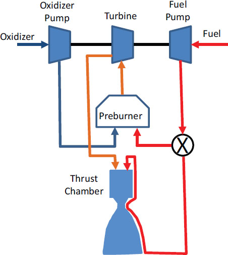
FIGURE 3.1 Highly simplified schematic of a closed-cycle, staged-combustion rocket engine. Because the preburner, turbine, and thrust chamber operate in series, the required pump pressure is higher compared to open-cycle engines. SOURCE: Air Force Research Laboratory.
There are several conventional options for vehicle thrust vector control; these would combine one or more thrust chambers with some type of non-toxic propellant reaction control subsystem, which will likely be required at a minimum to achieve roll control, but these will not be discussed here in detail.
Engine throttling, which is usually required together with control of the mixture ratio, is accomplished with a complex combination of flow bypass valves, throttle valves, and fixed bias and calibration orifices that are inserted during engine and hydraulics system build-up, calibration, and hot fire tests. All liquid RP-1 enters the thrust chamber cooling jacket prior to entering the MCC injectors and is mixed with the oxidizer-rich preburner exhaust gases to achieve the final main chamber combustion process. The liquid cooling jacket (heat exchanger), together with some film cooling of the MCC chamber wall, maintains the MCC at an acceptable operating temperature while allowing the necessary engine combustion efficiency and associated Isp.
3.2.1 Hydrocarbon-Fueled Booster Engine Risk Assessment
In considering the hydrocarbon-fueled ORSC rocket engine that will serve at the MPS for the reusable booster, the committee identified 12 risk areas:
• Combustion stability. Combustion stability physics for high-pressure liquid-liquid preburners and the MCC gas-liquid injectors for LO2/RP-1 ORSC engines are not well understood in the U.S. rocket industry. Combustion instability issues have plagued many rocket engine development programs during the past 60 years. Both physics-based modeling and a well-defined test program will be required to achieve and demonstrate the required stability margins for both combustion devices and thereby retire these risks. The Air Force Office of Scientific Research, in close cooperation with AFRL’s rocket propulsion laboratory at Edwards Air Force Base, has been making significant investments to analyze, predict, and defeat the combustion instability problem in liquid oxygen, hydrocarbon (LO2/HC) engines.
• Injectors. The new ORSC injector will most likely be based on a co-axial swirl design that will have to be tuned to MCC frequencies and set up with either acoustic cavities and/or baffles to ensure stable engine operation. Also, thrust-scaling relationships will have to be established through a combination of analysis and empirical data. While this is not presently seen as a major risk, there will have to be a dedicated experimental testing effort to tune the injector and chamber at the subscale and then the full-scale levels.
• Operation in high-pressure, oxygen-rich environments. High-pressure, oxygen-rich environments can be very hard on inert materials, and dangerous conditions can result following initial failures that are difficult to contain when trying to recover to a safe operating state. This type of environment is unique to the ORSC engine. As described above, in an ORSC engine all oxidizer consumed in the engine combustion process is first used to drive the TPA turbine, resulting in high-power margin and a relatively low operating temperature. The resulting oxygen-rich environment is also relatively clean, such that no soot or other residual combustion product deposits are generated during normal operation. Because of these unique conditions, the ORSC cycle generates high-pressure oxygen rich environments that present compatibility challenges for traditional turbine and ducting materials.
• Physics-based analytical models. Another risk for the RBS MPS is a fundamental lack of fully anchored physics-based analytical models for ORSC engines. In the anticipated fiscal environment of limited budgets and short development schedules available for RBS development, reliable and accurate analytical models and tools are critical for the successful and cost-effective completion of the planned RBS DDT&E program. Accurately anchored models enable a reduction in the number of design fabrication cycles and, most significantly, expensive test cycles that were required for past rocket engine development programs. The analytical model development needs to be multiscale, with modeling ranging from subscale components to subassembly levels such as the power head (TPA, preburner, and flow control valves) as well as at the full-scale ORSC engine level. This approach will ensure that validated analytical models are developed logically and accurately and that they are well anchored so that validated models at each step of the design process will be available for the ORSC engine when scaling to higher thrust levels. These same models will also benefit other future ORSC engine development work by accelerating and reducing the total number of expensive tests required.
• Valves/sensors/actuators. Some development effort will be required for the necessary reliable advanced fluid valves and control elements to enable a wide range of throttling, mixture-ratio control for proper and efficient propellant utilization, engine balance and calibration, thrust vector control (TVC), IVHM, and various other engine controls. These control elements must have modern, accurate sensors and be fully integrated with an automated digital MPS and engine control system, with the vehicle adaptive guidance and control system, and with the IVHM.
• Thrust level. The RBS ORSC engine thrust level requirement described in Air Force presentations to this committee is highly ambiguous. It was stated that the thrust requirement for RBS was anywhere from 350,000 to 500,000 lbf, which is inherently a problem from the standpoint of engine size and injector scaling and of possible high-pressure instabilities. The requirement became more complicated when Air Force briefers said several times that they might be interested in using the new American ORSC engines to replace the Russian RD-180 for the EELV program, which operates at thrust levels between 800,000 and 1.1 million lbf; this would pose a significant engine scaling problem and a much higher level of risk. The thrust level requirement should therefore be established early in the RBS development program and maintained at that level to avoid additional complications. If the Air Force wants to make the new engine compatible with the thrust requirement of NASA’s Space Launch System (SLS), which is stated to be 1.1 to 1.2 million lbf, this ambiguity would also have to be resolved to enable a single, focused ORSC engine development program without any additional complications that could lead to large program cost and schedule overruns.
• Systems engineering. The Air Force presenters offered little description of the RBS needs and/or requirements for system engineering and integration of the MPS and the other major systems into the RBS vehicle. These requirements must be firmly established early in the development process to avoid serious conflicts, unnecessary complications, and, worst of all, requirements creep, before program critical design review and flight certification. If these design requirements are not firmly established and maintained early in the program, there will be a high probability of serious cost overruns and schedule slippage.
• Power balance. Overall engine power balance and flow calibration and control with robust margins and tolerances for wide operating variances must be established early and verified by testing. Otherwise there will certainly be problems with off-nominal operating conditions, which often occurs later in the program or, worst of all, during actual flight. There must be demonstrated anomaly and off-nominal operating capability and robust margins designed into the more complicated ORSC engine to avoid failures that would be catastrophic during flight.
• Turbomachinery. There are always risks with new engine turbomachinery. Because of the high-pressure preburner operation, boost pumps need to be used in the engine and as part of the overall cycle. Engine start-up transients and shutdown sequences will all have to be established and fully characterized for this more complicated ORSC, multicomponent engine to ensure safe and repeatable operation. This is not considered to be a major risk, but it is a moderate risk that will have to be addressed during the design and development process with a focused, dedicated effort that will have associated costs.
• Long-life bearings. High-speed, long-life reusable turbomachinery shaft bearings will have to be developed and verified for all ORSC engine rotating machinery. This is a low-to-moderate-risk concern but one that must be explicitly addressed because bad bearing choices and subsequent integration into the engine can lead to serious problems later in the DDT&E program. This happened more than once in past programs such as the SSME, when bearing issues were discovered after a number of space shuttle flights perceived to be successful.
• Reusability: Other than the SSME, there has been almost no requirement for multiple reuses of U.S. rocket engines. Typically, additional life margin is designed in and demonstrated on all rocket engines to allow for hot-fire testing and even retest before flight. The question of how many engine reuses will be required prior to routine maintenance and scheduled engine overhauls must be answered. This concern is not a major risk, but it is rather a moderate risk that must be mitigated because it is a new requirement for an ORSC engine that has not been previously developed by U.S. industry.
• Materials. The last risk, a moderate one, is the mechanical and dynamic design approach and especially the materials to be used for hot, oxidizer-rich, hot-gas ducts from the preburner, which may require flexjoints or axial joints and other complications. As mentioned above, this risk area will have to be empirically evaluated before committing to a design.
Thus, the principal technical risks associated with the development of a LO2/RP ORSC rocket engine concern combustion stability and operation in the high-pressure oxygen-rich environment. Significant additional basic and applied research on combustion stability will be necessary before analytical tools are available that allow confident prediction of combustion instabilities. This work is under way at AFRL, but significant improvement in prediction capabilities cannot be anticipated in the near term. Fortunately, empirical techniques are available to “de-tune” the combustion system if instabilities arise, so this risk is principally one that will need additional development time and resources will be required if instabilities arise as the engine is scaled up during its development phase.
The risk associated with the oxygen-rich operation is fundamental and potentially more difficult to overcome. It is well known that Russian engine designs have overcome this material incompatibility challenge by using inert enamel coatings on traditional high-strength turbine alloys and hot-gas ducting. The alloys provide the structural load support, while the enamel coating provides the requisite hot-oxygen-compatible and/or protected surfaces. This type of solution has been used on Russian ORSC rocket engines for over 50 years and is used around the world for gas-turbine applications for jet engines and domestic power generators. There are at least three flight-certified Russian ORSC engine designs (RD-170, RD-180, and NK-33) that are well known to the U.S. rocket engine industry but not produced in the United States. Through various business arrangements with the Russian engine manufacturers, the basic design for these engines is well known and understood by the U.S. manufacturers—
namely, Pratt and Whitney Rocketdyne (PWR)1 and Aerojet.2 Each company sells a version of different Russian engines (e.g., PWR sells the RD-180 and Aerojet sells the NK-33) to U.S. launch vehicle suppliers.
Another oxygen-rich compatibility approach is to develop and use a hot-oxygen inert parent material.3 This approach is being attempted by the AFRL and large engine contractors (PWR and Aerojet) with some successful results already having been reported. PWR has developed a new hot-oxygen-compatible material called Mondaloy and has been evaluating its applicability and durability in hot oxygen-rich environments. To date, only small coupon pieces of Mondaloy have been manufactured, and the statistical basis for the thermal and mechanical properties needed for engine development is currently lacking. As such, basic issues with weldability, fatigue, and fracture remain to be investigated.
Currently, the Russian-developed enamel coatings are a far more mature and proven technology. However, application of these special coatings and/or advanced materials to U.S. ORSC engine designs has not been fully proven, so a comprehensive risk reduction program will be required. This risk mitigation effort must be focused on developing and proving a new hot-oxygen-compatible parent metal alloy or on verification of a coated material system capable of multiple reuse for the turbine and hot-gas flow-path components similar to the Russian solutions. Thus, if the known coatings, which are inert and will not react with hot oxygen, become the preferred approach, the risk mitigation effort will have to ensure that the coated engine elements are sufficiently durable for multiple reuse under all the necessary environmental exposures. In short, the program will have to verify coating durability under all relevant conditions and demonstrate traditional hot oxygen compatibility to be certified for a flight RBS-ORSC engine that launches an RBS.
The committee believes that in spite of the ORSC engine risks and concerns discussed above, there already exists an extensive database and success with this type of engine around the world. Table 3.4 lists all LO2/HC engines using either open- or closed-cycle designs that have been flown or are flight qualified throughout the world. As can be seen from this table, ORSC engines have been or are about to be flown on launch vehicles in the United States (all Russian designed and built), Russia, Ukraine, India, China, and South Korea. This extensive successful flight history and development experience should provide confidence for the development of a LO2/HC engine for the RBS booster. Many of these LO2/HC-powered launch vehicles have successfully placed large payloads of all kinds into their required Earth orbits or onto space-science trajectories throughout the solar system. This long history of success also includes putting many human beings in space as well as on the moon. So, these past successful experiences on both kinds of LO2/HC engines certainly provide assurance that a completely new ORSC engine can be developed here if adequate resources, time, and planned reserves are devoted to an affordable and reasonable program.
3.2.2 Hydrocarbon-Fueled Booster Engine Risk Mitigation
In addition to its extensive and successful EELV flight experience with hydrocarbon booster engines, the Air Force described to the committee the types of hardware technology demonstrations and risk mitigation programs that AFRL has been pursuing. These technology programs are briefly described below together with a short overview of NASA’s hydrocarbon engine development activities.
The AFRL has been conducting a joint rocket technology program with industry, the Integrated High Performance Rocket Propulsion Technology (IHPRPT), to advance all forms of rocket propulsion technology, including hydrocarbon boosters, for about the last 20 years. The goals for the hydrocarbon booster portion of IHPRPT are summarized in Table 3.5.4
_____________
1 A. Weiss, Pratt and Whitney Rocketdyne, “Reusable Hydrocarbon Rocket Engine Maturity for USAF RBS,” presentation to the Committee for the Reusable Booster System: Review and Assessment, February 16, 2012. Approved for Public Release.
2 J. Long, Aerojet, “Reusability and Hydrocarbon Rocket Engines – Relevant US Industry Experience,” presentation to the Committee for the Reusable Booster System: Review and Assessment, February 16, 2012. Approved for Public Release.
3 R. Cohn, Air Force Research Laboratory, “Hydrocarbon Boost Technology for Future Spacelift,” presentation to the Committee for the Reusable Booster System: Review and Assessment, February 16, 2012. Distribution A–Approved for Public Release.
4 R. Cohn, Air Force Research Laboratory, “Hydrocarbon Boost Technology for Future Spacelift,” presentation to the Committee for the Reusable Booster System: Review and Assessment, February 16, 2012. Distribution A–Approved for Public Release.
TABLE 3.4 American Heritage or Other Available Source Hydrocarbon Rocket Engines: Previously or Currently in Use, or in Development
| Rocket Engine | Manufacturer/ Supplier | Cycle | Thrust Level (lbf) / Vacuum Specific Impulse (s) | Status | Application | Comment |
| RS-27 MD-1 MA-7 | Pratt and Whitney Rocketdyne | GG | 200K S.L., 237K ALT / 303 | Flown hundreds of flights (~800) | Delta II and A2L Previous Thors, Thor Delta, and Delta III | |
| MA-5A LR-89/ LR-105 | Pratt and Whitney Rocketdyne | GG | 430K (booster)+60 (sustained) / 297 | Flown hundreds of times on Atlases; Project Mercury many flights (1,404) | Atlas family up to satellite launch vehicles | |
| H-1 | Pratt and Whitney Rocketdyne | GG | 200K S.L., 205K ALT / 301 | Flown many flights (152) | Saturn 1B, Jupiter, and early Thor Deltas | |
| F-1 | Pratt and Whitney Rocketdyne | GG | 1,522K S.L. / 307 | ~65 flights | Saturn V/Apollo | 5 used in first stage |
| RD-180 | Pratt and Whitney Rocketdyne, Russian-derived NPO Energomash | ORSC | ~860K S.L., 933.4K ALT / 337 | ~10 flights | Atlas III and V | Two TCAs, one pump |
| RD-170 | NPO Energomash | ORSC | ~1700K / 337 | Flown many times | Buran, Zenit, Proton | Four TCAs |
| S-3D | Pratt and Whitney Rocketdyne | GG | 80K / 310 | 46 flights | Jupiter/Juno | |
| AJ-87 AJ-1 AJ-3 | Aerojet | GG | 300K / 249 | Flown many times on ICBM test flight | Titan-I first stage | |
| AJ-91 | Aerojet | GG | 80K / 310 | Flow many times on ICBM test flights | Titan-I second stage | |
| NK-33 (AJ-26) | Aerojet | ORSC | 340K S.L., 380K ALT / 330 | Intended for use on Russian N-1 Moon launcher first stage | Developed for Russian N1, to be used on Taurus II (Antares) | PC = 2,109 psia |
| NK-39 | Khrunichev/ Aerojet | ORSC | N-1 second stage | Developed for Russian N1, intended for use on K1 | ||
| RS-84 | Pratt and Whitney Rocketdyne | ORSC | 1,050K S.L., 1,123K ALT / 338 | Finished PDR; cancelled by NASA | Intended for 100 missions, reusable launch vehicle | Incorporates advanced technology items, advanced materials, enhanced water-cooled nozzle |
| Merlin family | SpaceX | GG | ~80K / ~302 | Flown | Falcon I, 9 and 27 | Privately funded development |
| Other miscellaneous Russian | NPO Energomash | ORSC | Various / ~330 | Some flown | Various Russian and Ukrainian Rockets | RD-190 |
| Rocket Engine | Manufacturer/ Supplier | Cycle | Thrust Level (lbf) / Vacuum Specific Impulse (s) | Status | Application | Comment |
| MC-1 (Fastrak) | NASA/Marshall Space Flight Center in-house | GG | ~75K / ~280 | Advanced development, many tests | Looking for one, almost for X-34 | |
| YF-100 | China, Inc. | ORSC | 260K S.L., 301 ALT / 336 | Flown on Long March | China’s Long March launch vehicle 5, 6, and 7 | |
NOTE: ALT, at altitude; GG, gas generator; ICBM, intercontinental ballistic missile; lbf, pounds force; ORSC, oxygen rich, staged combustion; PC, combustion chamber pressure; S.L., sea level; TCA, thrust chamber assembly, K, thousand.
TABLE 3.5 Integrated High Performance Rocket Propulsion Technology (IHPRPT) Hydrocarbon Boost Technology/Performance Advancement Goals
| Goals | IHPRPT Goals Related to Reusable Booster System |
| Specific impulse (s) sea level/vacuum | +15% |
| Thrust to weight sea level/vacuum | +82% |
| Production cost | −50% |
| Failure rate | −75% |
| Mean time between replacement (cycles) | Defined |
| Mean time between overhaul (cycles) | Defined |
| Turnaround time (h) | Defined |
| Throttle range | Defined |
| Sustainability | Must derive from sustainable materials and processes |
SOURCE: Richard Cohn, Air Force Research Laboratory, “Hydrocarbon Boost Technology for Future Spacelift,” presentation to the Committee for the Reusable Booster System: Review and Assessment, February 16, 2012. Distribution A: Approved for Public Release.
Critical RBS technologies being studied and developed under ongoing AFRL propulsion R&D programs are summarized in Figure 3.2. The hydrocarbon boost (HCB) Phase II demonstration program aims to develop technologies to support the ORSC LO2/RP engine capability. Conducted by both Aerojet and PWR, this program aims to mature advanced hot-oxygen-rich-compatible materials and coatings as well as engine components such as pumps, advanced hydrostatic bearings, valves, actuators, preburners, igniters, main thrust chambers and new engine controllers, IVHM systems and associated sensors. As seen in Figure 3.2, the technology development associated with the HCB Phase II demonstration program and the Advanced Liquid Rocket Engine Stability Technology (ALREST) program are scheduled to run through the year 2020, which would limit technology contributions from these programs to any near-term RBS development activities.
The ALREST combustion stability effort is focused on development of a fundamental understanding of combustion instabilities in high-pressure LO2/RP combustion systems. These two efforts are planned for completion in 2020. Additional efforts under way include assessment of the characteristics of Mondaloy and development of IVMH diagnostic techniques applied to booster engines.
NASA has also been conducting advanced ORSC engine development programs over the last 15 years, working to solve many of the same advanced technology problems as those that the Air Force has been addressing.5 Several years ago NASA Marshall Space Flight Center (MSFC) funded a new ORSC engine program known as the RS-84.
_____________
5 D. Lyles, “NASA’s Reusable Stages and Liquid Oxygen/Hydrocarbon (LOX/HC) Engines,” presentation to the Committee for the Reusable Booster System: Review and Assessment, February 17, 2012. Approved for Public Release.
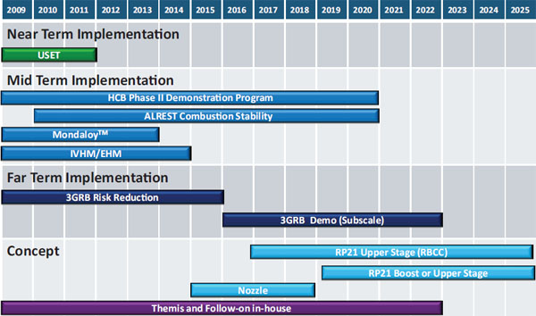
FIGURE 3.2 Air Force Research Laboratory Liquid Rocket Engine Roadmap as of fiscal year 2012. SOURCE: Richard Cohn, Air Force Research Laboratory, “Hydrocarbon Boost Technology for Future Spacelift,” presentation on February 15, 2012. Distribution A–Approved for Public Release.
This engine program proceeded through the preliminary design phase and was able to conduct some advanced prototype component design, manufacture, and test before it was canceled because it had no firm mission requirement and the NASA budget did not support sufficient advanced technology funds. Nevertheless, some successful component-level results were achieved that are now directly applicable to a new Air Force ORSC engine program.
NASA also worked jointly with the Air Force on an advanced technology program known as the Integrated Powerhead Demonstration (IPD). The IPD program was initiated by the Air Force but soon evolved into an effort jointly funded by AFRL and NASA MSFC with all hot-fire testing conducted at the NASA Stennis Space Center. The power head was to be integrated into a full-flow staged-combustion engine, where all propellants (in this case LO2 and LH2) flow through oxidizer-rich and fuel-rich preburners that power separate fuel-pump turbine and oxidizer-pump turbine, respectively. The hot-gas exhausts from each preburner flow into the MCC through a gas-gas injection system, making 100 percent of the propellant energy available to produce thrust. The IPD was designed as a ground-based demonstrator for an engine that would produce 250,000 lbf thrust. It was designed, built, and successfully tested, thereby demonstrating compatibility for high-performance and long-life components, materials, and technologies for reusable booster engine applications and (for the first time) a gas-gas injection MCC. After the successful tests at NASA Stennis, the program was terminated by the government, also for a lack of funding and a lack of a well-defined mission requirement. The successful IPD demonstration led to improved understanding of advanced engine components, and many of these results will be directly applicable to advanced component development associated with any type of new ORSC engine.
NASA has recently announced a requirement for a new ORSC engine in the million-pound thrust class for its new SLS Advanced Liquid Strap-on Booster (ALSB). The procurement and conceptual design activities are currently under way for a program that will demonstrate significant risk mitigation results for this new ORSC
engine. Even though the SLS ALSB engine thrust requirement is currently higher than needed for the Air Force RBS, NASA has announced plans to develop advanced technology materials and components that are applicable to both the SLS ALSB program and the RBS ORSC program; the SLS-ALSB risk mitigation program might therefore make a significant contribution to the Air Force program.
As the risk associated with hydrocarbon booster engine development is mitigated, the performance of a new rocket engine will eventually be demonstrated through extensive testing. Previously, new engine verification testing required years of very expensive testing. These efforts were being performed before very sophisticated computer design and simulation tools had become available. As computer capability increases, the belief is that the testing once required can be significantly reduced and that “cut-and-try” will be replaced with “simulate, test, verify and improve.” The cost saving associated with this new approach has not yet been fully demonstrated.
In conventional engine development, new engine design validation testing includes testing at the subscale, component, and subsystem level as well as in full flight configuration. At the component level, the required test facilities can be modest and typically include fluid flow and high-pressure testing of injectors, nozzles, pumps, and thrust chambers. The modest facilities can be used to conduct injector spray tests with cold-flow tests of the regenerative part of the combustion chamber before the full testing of ignition and ramp-up tests over a wide range of operating conditions. Engine combustion stability through all throttle levels as well as dynamic and spontaneous stability conditions is a key performance metric for both the MCC and the pressure preburner, which operates at much higher pressure. Sea-level and altitude simulated testing can be performed depending on the application. In addition to reviewing the engineering data after each subsystem test, the components are evaluated for potential failure.
Testing is generally highly instrumented to allow for verification of overall performance under a variety of performance conditions as well as to validate or provide feedback to analytical models. If sufficiently engineered into the test plan, early testing and evaluation can be used to improve system design for better performance, reliability, and safety. Detailed verification testing typically uses instrumentation, including flow meters, steady-state pressure transducers, thermocouples, high-frequency pressure measurements, strain gauges, accelerometers, and sophisticated laser and optics techniques6 to provide detailed information on the performance of large rocket engines under widely varying conditions.
As the required testing moves toward full system-level testing, there are only a few facilities available. NASA, PWR, and Aerojet all use the NASA Stennis facility, a national test facility allowing a range of rocket propulsion testing from component- to engine- to stage-level testing. As of May 3, 2012, Aerojet had conducted eight AJ-26 hot-fire acceptance tests at the Stennis facility.7 The RBS rocket engine testing will also be able to use this same facility. There are also limited rocket test facilities at AFRL/Edwards Air Force Base, commercial facilities at the Mojave Space Center, and contract facilities such as Wylie Labs. These facilities could be available as backup or to handle overflow and surge needs. Additionally, SpaceX has developed a facility at McGregor, Texas.
The cost realities for a rocket engine development program to support the RBS will be strongly impacted by the number and type of tests required for either an existing (AJ-26) or a new rocket engine design and the availability of testing facilities. With the goals of increasing reliability and reducing operating costs for the RBS, it will be vital to incorporate as early as possible the many sensors and control elements to be used in the IVHM system appropriate to the rocket engine. This will allow evaluation of the effectiveness of these sensors and controls and of the IVHM system so as to assess rocket engine performance and its ability to respond to off-nominal conditions.
The second principal technology risk area is associated with the rocketback RTLS maneuver. As described in Chapter 2, the reusable booster reorients itself following stage separation and the MPS is used to cancel the downrange component of momentum and provide sufficient return velocity such that the booster can return unpowered
_____________
6 NASA, Rocket Engine Technology Test Bed Practice, NASA Preferred Reliability Practices, Practice No. PT-TE-1427, available at http://engineer.jpl.nasa.gov/practices.html, p. 4.
7 J. Long, Aerojet, “Reusability and Hydrocarbon Rocket Engines–Relevant US Industry Experience,” presentation to the Committee for the Reusable Booster System: Review and Assessment, February 16, 2012. Approved for Public Release.
to the launch site. While this trajectory is novel and enables the RTLS operation needed in a reusable vehicle operating from coastal launch sites, the maneuver introduces technology risks that must be considered. These risks are associated with MPS throttle requirements, aerodynamics, thermal protection, and propellant management.
The MPS engine throttle challenges are associated with the significantly different thrust levels associated with lifting the full RBS stack as compared to the thrust requirements for the rocketback maneuver where the engine is propelling the near-empty booster stage. In the baseline RBS program description, this thrust disparity is met by using five AJ-36 engines for liftoff and one throttled AJ-26 for the rocketback maneuver. This thrust disparity challenge is much more difficult if using one or two engines as the booster MPS. The issues associated with engine throttling were discussed in the preceding section.
The aerodynamic, thermal management, and propellant management issues are discussed in the following subsections.
3.3.1 Aerodynamics Risk Assessment
The proposed rocketback maneuver to be executed by the first stage involves complex aerodynamic interactions that must be investigated during risk-reduction phases of the RBS development. Prediction of the vehicle aerodynamics is complicated by three principal factors: (1) high-speed, low-Reynolds-number flows, (2) rocket plume interactions, and (3) the need for high aerodynamic efficiency to minimize drag and associated DV requirements during the rocketback maneuver.
As shown in Figure 2.4, the RBS staging is envisioned to occur at altitudes above approximately 50 km, which is in a flight domain where vehicle boundary layers are predominately laminar and uncertainties in vehicle aerodynamics can be dominated by boundary layer separation phenomena. Furthermore, the approximate 180-degree turn creates a broad spectrum of transient aspect angles for the winged RBS, generating complex three-dimensional transient flow structures. This situation is further complicated by a lack of existing ground test facilities able to produce the Mach number/Reynolds number simulation environment that will allow collection of required aerodynamic data.
The second factor impacting the vehicle aerodynamics concerns the plume interactions that will occur during the rocketback maneuver. With the rocket operating at highly underexpanded conditions, the exhaust plume will expand and disrupt the flow over the aft end of the RBS first stage. The degree of plume interaction will be further complicated by chemical reactions between the hot exhaust gases and the ambient airstream. Accurate prediction of the vehicle aerodynamics during the rocketback maneuver will be required to ensure that sufficient vehicle control is maintained during the maneuver.
The final factor impacting the vehicle aerodynamics concerns the need for high aerodynamic efficiency during the glide portion of the trajectory. At the completion of the rocketback thrusting, the first stage is projected to be at an altitude significantly higher than can be sustained for equilibrium glide, so the vehicle will fall through its desired altitude and use lift for recovery to the equilibrium glide trajectory. Conducting this pull-up maneuver in an efficient manner is critical to maintaining sufficient kinetic energy to enable RTLS. Once on its equilibrium glide trajectory, the vehicle must operate with high aerodynamic efficiency (i.e., high lift-to-drag ratio) to provide for sufficient glide range to return to the launch site. The achievement of this high aerodynamic efficiency is complicated by the configuration of the RBS first stage, which will likely have a center of gravity well aft of conventional atmospheric flight vehicles owing to the aft location of the large rocket boosters, with subsequent large unstable lateral aerodynamics.
These risk factors are made more challenging by the large uncertainties that exist in the atmospheric models for altitudes above 100,000 ft. These uncertainties will need to be accommodated in both the aerodynamic design of the reusable booster and in the adaptive guidance and control system.
3.3.2 Thermal Protection/Thermal Control Risk Assessment
The technical information presented by the SMC and AFRL to the committee on identification of technology risk associated with the development of the RBS did not list any risk associated with thermal protection or thermal
control. This conclusion was substantiated in presentations by four aerospace companies in their respective responses to the question, What are the major technology risks associated with realization of a RBS for space lift? This conclusion is based on the results of a number of Air Force and NASA studies on reusable flyback booster systems, where the staging would occur between Mach 3.5 and 7, thereby avoiding the shuttle orbiter-type extensive thermal protection system, which experienced Mach 25+ reentry conditions and their associated extreme heating and thermal shock.
The rocketback maneuver is currently the favored RBS approach, but its use presents uncertainty with respect to thermal protection and thermal control.8 RTLS recovery has been analyzed in considerable detail, specifically for the space shuttle since it was a primary ascent abort mode, but it was never tested during development nor was it necessary to exercise it during any of its 135 operational flights.
The concerns of the committee associated with the RBS thermal protection system are tied to plume-vehicle interaction, structural loading on the control and aero surfaces, and base heating depending on the engine gimbal authority required for the maneuver. In principal, these concerns present no fundamental technology risk to developing an acceptable thermal protection system for RBS; however, the loads generated by these complex interactions need to be accurately characterized.
Relative to RBS thermal control, the existing component, subsystem, and system design concepts needed for RBS are sufficiently mature that they will likely require relatively little development work to meet RBS requirements. However, operational requirements should be considered in the system design. For example, if there were a requirement for thermal conditioning that might result in long hold times during launch operations and where ground conditioning is not available, then this situation could result in a requirement for onboard thermal control, which might increase launch vehicle weight.
Most of the first stage propellant is used in accelerating the launch vehicle to the second stage separation condition. As a result, the rocketback RTLS maneuver is executed with near-empty first stage tanks. Accurate management of both acceleration magnitude and direction during the maneuver will be needed to maintain the propellant flow throughout the maneuver. A recent Air Force white paper9 states that a major objective of the Pathfinder program is to address the technical challenge of propellant management (slosh and propellant agitation) during the rocketback maneuver. This challenge, like that of predicting aerodynamic load, can be addressed by developing and experimentally verifying the propellant slosh and dynamics models that will be used to predict propellant conditions and to design propellant management devices for the operational RBS.
The white paper goes on to state that “as in the case of aerodynamics, scaling design factors are needed to match the operational propellant conditions. These scaling factors include the present volume of propellant and gas (ullage) in the tanks during the rocketback maneuver. Appropriate similarity parameters will be used in the design of the pathfinder vehicle and the selection of flight test parameters.” The committee believes that flight experience, propellant management and slosh control technology, and existing data can be leveraged to manage propellant and control slosh during the rocketback maneuver and that these propellant concerns will be addressed as part of the Pathfinder program.
3.3.4 Rocketback RTLS Maneuver Risk Reduction
Simulating and understanding the aerothermodynamics of the unique rocketback maneuver does not lend itself to wind-tunnel investigations. Thus, computational fluid dynamic (CFD) models must be adapted to simulate and predict the maneuver, and modeling the flight regime of Mach 5 to 7 at altitudes above 50 km will require
_____________
8 Air Force Research Laboratory, “AFRL Portfolio: Responsiveness & Reusable Boost System (RBS),” presentation to the Committee for the Reusable Booster System: Review and Assessment, February 17, 2012, p. 24. Distribution A–Approved for Public Release.
9 D. Leggett, Air Force Research Laboratory, White Paper on the Pathfinder Program. Responses to Questions from the Committee for the Reusable Booster System: Review and Assessment, April 19, 2012. Available to the Public.
empirical validation of the calculated results. Accordingly, obtaining flight-type data relevant to RBS maneuvers would help in understanding the RBS unique aerothermal environment, thereby providing calibration and validation data for the models.
Pathfinder will specifically address verification of the predicted aerodynamic and aerothermal loads during maximum dynamic pressure and the booster’s rocketback maneuver. The Air Force has stated that the results of Pathfinder test flights can be scaled to the full-size RBS for the aerodynamic and aerothermal loads through the use of new improved CFD models.10 These codes and models are constantly being advanced at many levels and will likely be available for use in predicting load levels and flight environments for the operational RBS vehicle. The Air Force has also said that the Pathfinder test and characterization approach for matching actual flight conditions is more important than vehicle scale. Therefore, the committee believes that Pathfinder test data, together with the advanced CFD models, will yield much more realistic results than would be obtained from trying to realistically assess the dynamic loads generated in the rocketback RTLS maneuver using small models in a supersonic wind tunnel and certainly at much lower costs and risks than by immediately jumping into full-scale RBS or even mid-scale RBD vehicle flight testing.
AFRL has also stated11 that the Pathfinder flight test series represented a critical “risk reduction step” prior to attempting the rocketback turn and RTLS maneuvers with a larger-scale vehicle. It said it believes that while Pathfinder is only an intermediate step, the test data generated during its flight testing will be representative enough to anchor and validate the CFD codes that will be used to design the full-scale vehicle. Since there are no flight test data for such maneuvers, it is somewhat speculative to assume that the Pathfinder flight results will turn out as predicted. The expected results of Pathfinder test flights will certainly serve as a strong go/no-go decision gate for proceeding to design and develop a larger flight demonstrator or operational vehicle and will support that design effort.
While the planned Pathfinder project will likely provide data to support the RTLS concept, it would provide little data to validate the RBS booster thermal protection system design because its maximum Mach number capability is limited. An alternative approach might be considered to collect critical aerothermal data from low-cost sounding rockets launched from sites such as White Sands and NASA Wallops Flight Facility. With this type of fight test, an instrumented Pathfinder-like model could be boosted into relevant Mach number and altitude regimes. Once separated from the launcher, this model could be either command controlled or programmed to execute maneuvers elucidating the RBS 180-degree maneuver. Such models have many options—for example, parachute recovery and/or data stored in onboard memories, and/or telemetered data to ground stations.
The committee considers that the incorporation of IVHM technologies into the RBS will be necessary to meet general operability objectives and reliability goals, but few details on specific IVMH implementation needs were presented to the committee. In the absence of specific operability requirements, it is difficult to identify the parameters to be measured during RBS flight and ground operations.12 In the absence of this information, the committee assembled a tentative list of parameters to be measured in flight that might be important to a development program:
- Multiple engine temperatures,
- Structure temperatures,
- Selective vehicle skin temperatures,
- Strain loads throughout the structure and attachments,
_____________
10 D. Leggett, Air Force Research Laboratory, White Paper on the Pathfinder Program. Responses to Questions from the Committee for the Reusable Booster System: Review and Assessment, April 19, 2012. Available to the Public.
11 D. Leggett, Air Force Research Laboratory, White Paper on the Pathfinder Program. Responses to Questions from the Committee for the Reusable Booster System: Review and Assessment, April 19, 2012. Available to the Public.
12 Background information on IVHM developed for the Kistler K-1 vehicle may be found in G.E. Mueller, D. Kohrs, R. Bailey, and G. Lai, Autonomous safety and reliability features of the K-1 avionics system, Acta Astronautica 54(5):363-370, 2004.
- Accelerometers (distributed),
- Flow rates (LO2/RP-1),
- Chamber pressure (MCC and preburner),
- Propellant levels in tanks,
- Pressure drop across injectors,
- Turbine speeds,
- Turbine dynamics,
- Pumps: inlet and discharge,
- Boost pump dynamics,
- Valve positions,
- Specific on/off valve positions, throttle valve feedback,
- Potentiometric measurements for all actuators,
- Dynamic element feedback (close loop on internal commands), and
- Valve electrical currents.
Many of the parameters listed above are relatively straightforward to measure and integrate into an IVHM system if they are introduced early in the engine or vehicle development process. One big challenge in the development of an IVHM system for the baseline RBS concept concerns the application of critical diagnostic systems to the AJ-26, an existing engine that can tolerate only limited modifications.
In addition, parameters need to be measured during ground processing to allow assessment of vehicle integrity and readiness for flight, including the need to determine leakage in ducts, seals, valves, and the like; the potential for fatigue and other structural defects; an assessment of life remaining before next maintenance; functional checks of electrical continuity and response to actuation commands; and verification of sensor operation. These measurements, together with properly detailed nondestructive evaluation, will need to incorporate state-of-the-art inspection and evaluation techniques.
3.5 ADAPTIVE GUIDANCE AND CONTROL FOR REUSABLE BOOSTER SYSTEMS
This entire section is taken directly from the AFRL paper “Adaptive Guidance and Control for Reusable Booster Systems.”13
The reliability of today’s first-stage, expendable boosters is known to be approximately 97%, while the required system reliability goal for the future RBS is stated as 99.98%.Currently, expensive and time-consuming mission assurance tasks, such as hardware simulations and software verification, must be performed prior to each launch of expendable boosters to elevate the reliability to the 99% goal.
Adaptive, Guidance and Control technology has been identified by the Air Force Space Command as a critical technology that can significantly increase the reliability and responsiveness of future launch vehicles, including RBS. The objective of an AG&C algorithm is to enable the RBS to track its nominal trajectory under off-nominal conditions, or compute an alternate, but flyable, trajectory under severe cases of off-nominal conditions. Off-nominal conditions might be caused by a failure (or failures) in its subsystems: control effector subsystem (e.g., stuck aileron), propulsion subsystem (e.g., loss of thrust in one engine), or thermal protection subsystem (e.g., lower allowable heating limits). Table [3.6] below shows the subsystem failures between 1980-1999 for different countries’ launch vehicles.14
Given that the propulsion and avionics subsystems caused the failure 66% of the time, an AG&C algorithm designed to overcome those failure modes will likely improve the overall vehicle reliability. Results of an analysis conducted by Hansen illustrate how an adaptive action can potentially save the Reusable Launch Vehicle (RLV) from different subsystem failures.15 The results are shown in Table [3.7].
_____________
13 A. Ngo, Air Force Research Laboratory, Control Systems Development and Applications Branch, “Adaptive Guidance and Control for Reusable Booster Systems,” submitted to the committee, May 7, 2012.
14 I. Chang, “Space Launch Vehicle Reliability,” Crosslink, Winter 2001, available at http://www.aerospace.org/publications/crosslink-magazine/previous-issues/.
15 J.M. Hansen, “New Guidance For New Launchers,” Aerospace America, March 2003.
TABLE 3.6 Launch Vehicle Subsystem Failures, 1980-1999
| Country | Propulsion | Avionics | Separation | Electrical | Structural | Other | Unknown | Total |
| U.S. | 15 | 4 | 8 | 1 | 1 | 1 | 30 | |
| CIS/USSR | 33 | 3 | 2 | 1 | 19 | 58 | ||
| Europe | ||||||||
| China | 3 | 1 | 2 | 6 | ||||
| Japan | 2 | 1 | 3 | |||||
| India | 1 | 1 | 1 | 1 | 1 | 5 | ||
| Israel | 1 | 1 | ||||||
| Brazil | 2 | 2 | ||||||
| N. Korea | 1 | 1 | ||||||
| Total | 64 | 11 | 11 | 2 | 3 | 3 | 20 | 114 |
SOURCE: I-Shih Chang, Space launch vehicle reliability, Crosslink, Winter 2000/2001, pp. 23-32, available at http://www.aero.org/publications/crosslink/winter2001/03.html. Table reprinted with permission of The Aerospace Corporation.
TABLE 3.7 Launch Failures and Potential Adaptive Actions to Address Similar Failures in Future Reusable Launch Vehicles (RLVs)
| Date | Vehicle | Reason for Failure | Action to Save RLV with Equivalent Failure | |
| June 27, 1994 | Pegasus XL | Poor aerodynamic data | Adapt to data to maintain control | |
| October 20, 1998 | Ariane 5 | Shutdown due to engine roll torque | Abort landing trajectory targeted or abort deorbit and landing | |
| May 5, 1999 | Delta III | Engine failure | Abort landing trajectory targeted | |
| March 12, 2000 | Zenit 3SL | Second stage shutdown | Abort landing trajectory targeted | |
| July 12, 2001 | Ariane 5 | Combustion instability | Abort landing trajectory targeted | |
| September 21, 2001 | Taurus | Seized actuator | Abort landing trajectory targeted | |
SOURCE: J.M. Hanson, New guidance for new launchers, Aerospace America, March 11, 2003.
The fault-tolerance of the AG&C algorithm stems from its inherent ability to accommodate wide ranges of the launch vehicle’s dynamics and constraints. These variations arise from the vehicle’s subsystem failures during flight. The AG&C technology enhances the responsiveness of the RBS by reducing the time needed for contingency planning such as abort trajectory design and simulation during the mission planning phase of the launch preparation.
In general, an AG&C algorithm consists of three components: Trajectory Generation, Adaptive Guidance, and Reconfigurable Control. A diagram of the AG&C components and their interactions to the vehicle’s Onboard Diagnostics and Operations Control Center are shown in Figure [3.3].
In the Reconfigurable Control System block, an allocation algorithm distributes stabilizing commands to the working control effector (such as TVC actuators, engine throttling, RCS thrusters, ailerons, rudders, and elevators). The stabilizing commands are computed according to the required forces and moments to maintain the stability of the vehicle. In the event of an off-nominal condition, such as a control effector frozen in place, the Onboard Diagnostics detects and provides the failure information to the Reconfigurable Control System algorithm which in turn adjusts its distribution of commands to the remaining control effectors. Vehicle constraints and/or limiters on angular rates, accelerations, loads, angle of attack, and landing are also considered by the Reconfigurable Control System algorithm.
In the Adaptive Guidance System block, the vehicle’s flight path stability is maintained under both nominal and off-nominal conditions. Feedback gains are adjusted according to the inner-loop to control performance as well as the vehicle dynamics.
In the Trajectory Command Generation block, a new trajectory for the vehicle is generated when necessary so that the trajectory requires only forces and moments that can be achieved by the degraded capabilities of the vehicle while meeting critical constraints. An alternate landing site along with the aerospace constraints from the range system are provided to the Trajectory Command Generation block through the Operations Control Center. Besides interacting with the AG&C blocks, the Operations Control Center also communicates with Test Range network to receive the real-time updates of the ground and air constraints.
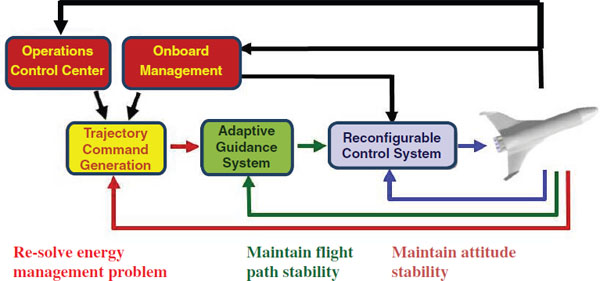
FIGURE 3.3 Major adaptive guidance and control elements. SOURCE: A. Ngo, Air Force Research Laboratory, Control Systems Development and Applications Branch, “Adaptive Guidance and Control for Reusable Booster Systems,” submitted to the committee, May 7, 2012.
The AG&C technology is targeted at an autonomous first-stage RBS that provides operationally responsive and reliable access to space. The integrated AG&C and Onboard Diagnostics facilitates these goals by allowing the autonomous RBS to detect and recover from degradation or full functional failure of control effectors, RCS thrusters, propulsion engines, and thrust vectoring gimbals without outside intervention, just as a skilled pilot can recover from failures in an airplane.
As discussed earlier, the RBS follows a novel return-to-launch-site (RTLS) trajectory. The AG&C system controls the vehicle throughout this mission, providing commands to aerodynamic control surfaces, reaction control thrusters, propulsion throttles, and thrust vectoring gimbals. Health management monitors the effectors and sends information that quantifies the capability of each effector to respond to commands. In the event of a failure, the AG&C system uses this information to reallocate control to the remaining effectors, calculate changes to the vehicle envelope, and to autonomously compute a new trajectory, if necessary.
The net effect of the AG&C technology is a significant increase in the reliability of the launch system. AG&C allows the booster to recover both from anticipated failures such as engine out and a wide range of unanticipated failures from which the robust control system can recover. Using these technologies, attaining a 99.98% reliable boost system appears feasible.
Technical challenges for the AG&C technology stem from the fact that the algorithm must perform its computations in real-time in the event of a failure(s). Two principal challenges deal with the computational requirements and convergence guarantees associated with the AG&C algorithms. Computational requirements are driven by the need for trajectory generation, which involves optimization methods that are usually quite computationally intensive and can stress real-time system capabilities. Convergence guarantees are associated with the generation of viable solutions to the trajectory optimization. Currently, this often requires involvement by the designer or engineer through trial and error, which is not practical for real-time systems operating in a dynamically changing environment. In recent years, considerable progress has been made in software development, efficiency, simulation, verification, validation, and hardware testing and these techniques can be applied to meet the above technical challenges.
AFRL has been developing the AG&C technology for over a decade for a wide range of next generation applications. Successful demonstration of AG&C algorithms during the approach-and-landing phase of flight has been performed using conventional test aircraft. For the reentry phase of flight, hardware-in-the-loop testing to examine the real time execution of the algorithm has been performed by Honeywell under contract with AFRL. Concurrent with the RBS Pathfinder flight demonstration program, AFRL is executing contracts with Honeywell to integrate, simulate and hardware-test the AG&C algorithms using high-fidelity simulations for all flight phases. This contract will use the Pathfinder and RBS flight dynamic models as they are developed to perform incremental testing: model-in-the-loop, hardware-in-the-loop, and potentially flight tests on the Pathfinder vehicle.
A number of additional technology risk areas were considered by the committee and are discussed in the subsections below. These areas are considered by the committee to pose less risk than the four principal technology risk areas, but addressing each of them during an RBS development program is recommended.
The sizing of an RBS system is sensitive to the inert mass fraction of both the reusable booster and the expendable upper stage. Thus, the structures of both stages will need to be efficient, yet sufficiently robust to carry the applied loads. There are 12 main factors to be considered in assessing the RBS structural design:
• The specific material of construction for each element of the RBS.
• The external environments that are anticipated to be imposed on the vehicle during all phases of the flight, including ignition, liftoff, abort, maximum angle of attack and dynamic pressure, staging, the rocketback maneuver, glide aerodynamic loads, and ground handling.
• The loads imposed on the payload by vehicle at liftoff; during the complete flight profile; at and during staging and any other known events (i.e., vibration, shock, and acoustic energy impact on the integrated payload); at payload injection into its initial transfer orbit; and upon landing.
• Manufacturing and assembly techniques that impact material selection and production methods (welding, brazing, and the like).
• Nondestructive inspection and evaluation methods, especially between flights, for a rapid-turnaround, reusable vehicle.
• Structural and material fatigue assessments and structure/component life remaining before scheduled maintenance operations, repair, and replacement (initial determination prior to liftoff and state of health). This is especially critical for reusable engines, tanks, and turbomachinery.
• Mass properties—weight, center of gravity, center of pressure, moments of inertia, and management of mass property balance (static and dynamic) during the complete flight profile.
• Structural release attachment and mechanisms.
• Attachment loads associated with launch stand support before and during liftoff.
• Low-level, long-duration ground, sea, and air loads resulting from transporting/shipping the RBS vehicle to and from the launch site and the manufacturer’s depot for rework, maintenance, and R&R.
• Impact loads/stresses from all aspects of the staging event and associated maneuvers and landing, both loaded and unloaded.
• Structural impacts of loads generated in flight by the RBS highly asymmetric configuration.
The baseline materials selected for RBS structures and tanks are currently all metal, probably either the best strength-to-weight aluminum and/or titanium alloys; however, the ever-increasing pressure to increase the propellant mass fraction may drive the consideration of composite materials for the RBS airframe structure and maybe even the tanks, where metal-lined composites may be attractive. Common bulkhead tanks (CBTs) are likely to be considered as development proceeds and weight savings are needed despite the inherent risks of a CBT and the associated operational difficulties of a CBT.
As discussed in Section 2.1, the Air Force described two variations of the proposed expendable upper stage for the RBS. One will be for small- to medium-size payloads and will be called the small expendable stage (SES) and the other will be for the heavier payloads and will be called the large expendable stage (LES). Both the SES and the LES will likely be mounted to the first stage by four structural hold down and redundant release attachment mechanisms. Depending on the specific upper stage employed, the separation event will initially impose loads on the booster primarily caused by shock, although likely to have some aerodynamic flutter content as well. A collision avoidance maneuver may be needed when either the SES or the LES separates from the booster.
When the dynamic pressure and aerodynamic loads are sufficiently reduced during upper-stage ascent, the payload fairing will be released and jettisoned. The environmental loads generated by this event will have to be accommodated but they will probably pose no unusual material or structural technology risk. The only risk that might be encountered would be one from some new requirement to save launch weight by introducing new and lighter materials, which could challenge the structural design and the design of the release mechanism.
From a structural design standpoint, the RBS LES, except for the attachment and release geometry and mechanisms, will likely be very similar to the upper stages now in use with EELVs. The propellant tanks will have to accommodate loads from the nonlinear attachment and subsequent separation; however, the loads analysis and analytical models should be readily adaptable from experience with the space shuttle’s unique geometry and the Delta IV Heavy side-mounted liquid boosters.
If a decision is made to use lightweight composite tanks, there will be additional technical risks having to do with the lightweight composites used to contain cryogenic propellants. There is still significant concern over the very negative experience with NASA’s X-33 cryogenic composite tanks. The TRL for using these composite materials with cryogens is still low, and much more technology development would be required. There is also the very important question of how to best mount large composite tanks on the vehicle’s primary structure and what type of fasteners or bonding techniques to use. The answer will depend heavily on the materials of construction and the design approaches. Then too, there is always the question of designing for distribution of flight loads. Should the loads be distributed through the tanks or around them or in some load-sharing combination? How will the design best be accomplished? Other design solutions such as engine structural mounts and thrust load accommodation are likely to be readily extractible from standard analytical techniques and past launch vehicle flight experiences.
An additional complicating factor for the reusable booster is that RTLS maneuver functions require additional hardware elements (wings, control surfaces, landing gear, and so on) that cause the RBS to suffer appreciable intrinsic mass penalties compared to conventional expendable boosters. The basic rocket equation,
![]()
where η is the mass fraction (the ratio of the fuel mass to the total mass), shows us that for a given DV capability, significant reductions in RBS mass require significant improvements in specific impulse or total-system mass fraction (fuel mass/total RBS mass). For ORSC LO2/HC engines, specific impulse gains greater than approximately 10 percent are unlikely. However, the hardware elements needed for the RTLS maneuver invite both invention and the consideration of new materials. For example, Elias, in his presentation to the committee,16 projected significant potential gains in structural material strength-to-weight ratio based on nanomaterial technologies such as large-scale nanotube structures. He stressed that the mass reductions stemming from such new materials are necessary for RBS-type systems to be cost competitive with next-generation expendable systems, especially in the emerging commercial arena. While large-scale nanotube structures are unlikely in the near future, significant reductions may be achieved by incorporating new fiber composite materials for the load-bearing structures.
While challenges exist in meeting inert mass fraction requirements for RBS, many of the structural design concerns about the best selection of construction materials should be readily resolved following flight testing of the subscale Pathfinder and the much lower cost RBD flight test vehicles. Thus, the principal technology risks for achieving the needed inert mass fraction of the RBS structure are associated with the structural materials and process selection and the accurate determination of the structural loads. Obtaining accurate flight profile aerodynamic, aerothermodynamic, and other environmental loads from subscale tests to enable validated and accurate CFD loads for design of the full-scale RBS is therefore essential.
_____________
16 A. Elias, Orbital Sciences Corporation, “Orbital Sciences Corporation Opinions on Launch vehicle Reusability,” presentation to the Committee for the Reusable Booster System: Review and Assessment, March 28, 2012. Approved for Public Release.
3.6.2 Power, Fluid Thermal, and Actuation R&D
While not considered a major technical risk, the RBS still must have its own power source during the full flight profile. Once the ground power umbilical disconnect separates from the booster at liftoff, the RBS will need a power source that is either accessible and replaceable or some type of rechargeable/regenerative power supply. There are four technically mature candidates to perform this function:
• Primary thermal batteries. These batteries are inexpensive, reliable and easy to activate, but relative to other power source listed here are heavy and will have to be replaced after every flight and mission abort.
• Chemical energy to power an Auxiliary Power Unit (APU). APUs have a long history of success on aircraft, Space Shuttle, etc., but their operations can be complicated and the APU expendables must be replenished after each flight.
• Fuel cells. Fuel cells offer higher efficiency with a compact footprint, but they are expensive, safety concerns remain, and they require recharging of expendables after each flight.
• Rechargeable/reusable batteries. Li-ion, NiMH, and other such batteries generally have a long life with proven high reliability and low maintenance without additional expendables, but they are expensive and require a readily available power source for recharging and regular conditioning.
The selection of the appropriate internal power source will be decided by selection of the optimum approach for meeting the concept of operations, reliability, and performance criteria. If RBS operability, including fast ground turnaround and responsiveness, are an Air Force requirement, rechargeable/reusable batteries for the short-duration booster flight are likely the best choice.
3.6.3 Assembly and Manufacturing
Modern capabilities for manufacturing and assembly of all types of vehicles throughout the world have greatly advanced in recent times. Incorporation of fully automated and robotic operations has greatly increased productivity for airplanes, automobiles, ships, mobile tool systems (e.g., tractors, lawn mowers, and the like) and even for the few expendable rockets being produced in the United States—Delta IV, Atlas V, and Falcon 9. The successful use of these advanced manufacturing methods for almost all modern vehicles has improved productivity and decreased cost and production time. The benefits of all the advanced, automated methods now in use have been widely recognized and are being employed by an increasing number of manufacturing companies the world over.
The current EELVs have adopted friction stir welding in the manufacture of their aluminum propellant tanks and adapters. This automated process generates less heat than conventional welding processes, results in a smaller heat-affected zone with its attendant poorer mechanical properties, and eliminates most defects and the need for weld repairs. If the RBS propellant tanks are made of aluminum, friction stir welding should be explored as the primary metal joining method.
The RBS baseline plan, while only planning to manufacture eight complete flight vehicles, may have real potential for cost savings using modern manufacturing technology approaches. In addition, it may be prudent to build these vehicles over a stretched-out span to permit incorporation of improvements as vehicles are built and to have an ongoing manufacturing capability if replacement boosters are needed. While a highly automated plant for booster manufacturing may initially be more expensive than the conventional option, it better accommodates personnel turnover and improves manufacturing quality. The ongoing production of upper stages and payload fairings for RBS can clearly benefit from a highly automated, modern manufacturing facility.
Accordingly, the committee believes that even with the initial requirement for only eight flight vehicles, producing the vehicles using the most modern, automated manufacturing and assembly methods would likely provide high payoffs. This approach will unquestionably improve the probability of meeting the stated RBS LCC goals, even including the high initial capital investment required to implement these advanced highly automated modern techniques.
Over the years the major space providers have been evolving their satellite and launch vehicle capabilities, incorporating new technology into existing designs. By way of contrast, other providers, such as Iridium and SpaceX have performed clean-sheet exercises by combining the use of state-of-the-art materials and state-of-the-art manufacturing techniques in their product lines to help reduce costs and increase reliability. Clean-sheet exercises, when done effectively, allow for incorporation of a holistic vision of the end-use system into the early concept design. Additionally, simplification concepts such as standardization and modularization as well as early systems engineering to incorporate IVHM diagnostic sensor systems can be designed into the system from the beginning and validated during testing. The manufacturing process can also be designed to run in parallel with the postflight maintenance and servicing.
The RBS high-performance expendable second stage will need to be developed to be operationally compatible with the newly developed reusable first stage in a manner that would allow meeting overall mission goals as described by the Air Force. The baseline second stage uses LO2/LH2 propellants owing to the inherent need for very high performance upper stages for heavy payload orbit injection (as was the case, for instance, for the Saturn S-IVB, the Delta IV, and the Centaur upper stage on Atlas I, II, III, and V). The need for high performance in the second-stage engine is especially true for the RBS concept, where the staging velocity is very low compared to an optimized expendable system. With the large DV requirement for the RBS second-stage, the projected overall launch mass of the RBS system would need to be much larger if a high-performance LO2/LH2 engine was not used.
The Air Force baseline approach for this high-performance upper-stage engine is to use the existing, flight-proven RD-25E—that is, the nonreusable version of the SSME that is being developed by NASA. Backup options for a high-performance upper-stage engine (such as the Russian-produced RD-0120) are also potentially available. Given this baseline approach and the potential availability of alternatives, the committee believes that development of the RBS upper-stage engine does not pose a significant technology risk. However, for the range of payloads initially described in the Air Force RBS launch model, the upper stage will be quite large and will require large, lightweight cryogenic propellant tanks. The chosen materials (metal or composites) may introduce additional technology risks. Tank technology concerns as well as questions of propellant management and the possible benefits of CBTs for LO2 and LH2 to save mass are discussed elsewhere in this report.
AFRL has been developing improved analytical prediction techniques for application to upper- stage engines in its Upper Stage Engine Technology program. In addition, the Air Force is now supporting an advanced upper-stage engine technology development program, the Affordable Upper Stage Engine Program, which is developing the technology base for a new high-performance, higher-thrust-level LO2/LH2 engine to ultimately replace the RL-10 family, which has been around and slowly evolving since 1962. Other than the J-2 engine used on Saturn’s upper stages and the SSME, the RL-10 and its various derivatives have served as the only high-performance, upper-stage engine for most U.S. launch vehicles (Delta IV, all Atlas/Centaur versions, and some Titan missions with a Centaur upper stage).
In addition to the baseline engine options of the RS-25E or RD-0120, AFRL has the option to develop a new scaled-up version (much higher thrust level) of an RL-10 class (high performance expendable) LH2/LO2 engine if neither the RS-25E or RD-0120 engines are available or suitable for the RBS upper stage. However, if a new upper-stage high-performance LH2/LO2 engine needed to be developed for any reason, this would add significant cost to the RBS development program, which was not briefed to the committee by any Air Force, Aerospace Corporation, or contractor presentations (or by any other entity).
3.7 OPERATIONS AND INFRASTRUCTURE
The baseline RBS development plan includes three launch sites: two at Cape Canaveral Air Force Station (CCAFS) in Florida and one at Vandenberg Air Force Base (VAFB) in California. The first RBS launch complex will be all new and built at CCAFS and will accommodate the RBS-Y full scale development vehicle. It will initially operate in parallel with the current CCAFS EELV launch sites. Once the Atlas component of the EELV program
is phased out, Atlas pads can be converted to accommodate the RBS, and the initial RBS-Y pad at CCAFS could also be used for RBS. There will be many design decisions at RBS facilities to manage cost but few technology decisions. Most operability enhancements envisioned for RBS infrastructure are being used or are currently in development for existing launch vehicles or other processing/manufacturing applications. In the opinion of the committee, the RBS facilities will face a design and cost control challenge but probably not be a significant technology development challenge.
Applicability of existing EELV infrastructure to RBS will be somewhat limited because the RBS booster is so large, especially its wing and vertical tails and its LES. Table 3.8 compares the medium-lift RBS with the Atlas V-551 EELV compiled from data provided by the Air Force, the Aerospace Corporation, United Launch Alliance, and contractors, whose representatives briefed the committee. This comparison can be used to identify which current Atlas infrastructure may be applicable for RBS use. Some existing Atlas EELV horizontal processing facilities may be usable as is or with reasonable modification. Existing launch control centers can probably be used for RBS with upgraded equipment. EELV vertical processing and some launchpad facilities may require major rework if the winged RBS booster with a piggyback-mounted LES will not fit. However, it still makes economic sense to modify current launchpad facilities to avoid lengthy environmental approvals for new sites and to take advantage of existing exhaust ducts, vehicle transportation equipment, propellant storage and transfer systems, fiber-optic communications, and payload air conditioning capabilities.
Processing operations at the launch sites will most likely be based on current EELV practices, since the RBS manifest for the Air Force is “launch on schedule.” Payload and expendable upper stage operations will follow current practices with enhanced automation, while those for the reusable booster will need to be modified to accom-
TABLE 3.8 Comparison of Reusable Booster System (RBS) (medium lift) and Atlas V-551 Evolved Expendable Launch Vehicle
|
RBS (approx.) |
Atlas V-551 |
|
|
Booster |
||
|
Diameter, Length (ft) |
17, 110 |
12.5, 106.5 |
|
Inert and Propellant Weight (klb) |
105, 900 |
41.7, 626.3 |
|
Number of Engine(s); Thrust (klbf) |
5 AJ-26; 1,655 |
1 RD-180 = 860 |
|
Wing, Tail Span (ft) |
60, 36 |
|
|
Solid Rocket Booster |
||
|
Diameter, Length (ft) |
5.2, 65.5 |
|
|
Number of SRBs, Weight (klb) |
5, 514.7 |
|
|
Number of SRBs, Thrust (klb) |
5, 1897.8 |
|
|
Second Stage |
||
|
Diameter, Length (ft) |
16, 130 |
10, 41.6 |
|
Inert, Propellant Weight (klb) |
38, 340 |
4.9, 45.9 |
|
Number of Engines; Thrust (klbf) |
1 RS-25E; 500 |
1 RL-10; 22.3 |
|
Interstage Adapter |
||
|
Diameter, Length (ft) |
12.6, 13.6 |
|
|
Weight (klb) |
8.8 |
|
|
Payload Fairing |
||
|
Diameter, Length (ft) |
18, 77 |
17.8, 76.8 |
|
Weight (klb) |
9 |
8.8 |
|
Spacecraft (to low Earth orbit) |
||
|
Weight (klb) |
50 |
41.5 |
|
Total Dry Weight (klb) |
200 |
626 |
|
Gross Lift-off Weight (klb) |
1,340 |
1,298 |
|
Total Sea Level Thrust (klbf) |
1,655 |
2,548 |
|
Stack Height (ft) |
180 |
225 |
|
Booster Diameter (ft) |
17 |
24 |
NOTE: The RBS data is approximate and conservative, to be used for comparative purposes only. SRB, solid rocket booster.
modate landing, “safing” of the vehicle (making it safe for ground crews to carry out needed handling activities) and turnaround for relaunch. The following subsections are arranged to reflect a launch system nominal (historical) processing flow, with RBS influences and deviations noted.
RBS operations may require changes to existing infrastructure and launch procedures. A review of the current practices and discussion of potential RBS impacts follows.
Current practice for an established launch vehicle requires submittal of a preliminary flight data package to Range Safety at L−60 days and a final data package at L−30 days. For each upcoming unmanned vehicle launch, the Range reviews the nominal planned vehicle trajectory and establishes limit lines. If the actual flight trajectory exceeds those limits, the Range Safety Officer destroys the vehicle. RBS use of AG&C may allow these limits to be relaxed to account for RBS’s ability to respond automatically to off-nominal conditions and still perform its mission. Range tracking must be performed by two independent sources.
The RBS will interact with the Range Safety and the Airspace Control systems during both launch and return. In neither regime is it likely that the booster will present new challenges, even to the Range Safety systems in place today, which are certain to evolve between now and when an RBS system would fly.
From the perspective of Range Safety, there is no significant difference between an uncrewed reusable system and an expendable booster. The same requirements for information about location, velocity, direction, and booster status, and need for a flight termination system will apply. Flight termination systems are well understood, and the RBS would present no new challenges.
The Federal Aviation Administration Office of Commercial Space Transportation (FAA/AST) is facing the challenge of handling uncrewed vehicles in the airspace today, and the committee believes that the challenges to doing so will be resolved long before the RBS is flying. FAA/AST has limited experience in supporting a crewed vehicle returning from space to a landing in the United States, but that experience will grow substantially over the next decade. The experience with autonomous entry into the airspace and landing is far more limited today (e.g., the X-37B). However, the ability to manage this kind of operation has been demonstrated and will likely not present any major barriers to RBS operations.
The various test and demonstration vehicles involved with the RBS, e.g., the Pathfinder, demonstrator and Y-vehicles, will probably be flown on traditional ranges. The Range Safety and Airspace Management requirements must be addressed during these phases of the program or alternatives found to the operational ranges.
Finally, the launch range will now have to support operations associated with the booster’s return to the launch base airstrip for landing. These operations are expected to be further complicated for the RBS Heavy with two returning boosters. Their return has to be staggered to permit sequential landing/exit from the runway. The Eastern Range has dealt with the space shuttle orbiter’s return for landing, and similar considerations apply for RBS. The orbiter returns with some residual Orbital Maneuvering System propellants, and the RBS booster will have remaining LO2/RP-1 and attitude control system (ACS) propellants. These must be off-loaded and the propellant systems made safe prior to towing the booster(s) to a ground maintenance facility.
3.7.2 Launch Readiness Reviews
Current expendable launch vehicles are subjected to a number of readiness reviews starting several weeks prior to launch. This process has been institutionalized over the past 60 years and with slight differences, is practiced by all government agencies and current launch system providers. The reviews are held with the launch service provider’s management, payload provider, launch customer, Range Safety, launch base management, and the engineering tiger team. To achieve responsive launch with RBS, this process will need to be significantly revised and shortened while maintaining launch system reliability. A major cultural change by all participants in the prelaunch process will be required to accomplish a more streamlined and less costly review process.
Current facilities at CCAFS and VAFB are suitable for RBS payload processing and fairing encapsulation. At CCAFS these include the Astrotech commercial processing facility, the Air Force defense satellite communications system processing facility (4-m diameter only) and shuttle payload integration facility; and the NASA vertical processing facility, spacecraft assembly and encapsulation facility, multipayload processing facility (4-m diameter only), and payload hazardous processing facility. These facilities support spacecraft storage, preparation, propellant loading, solid rocket motor and ordnance preparations, dynamic balancing, adapter mate and encapsulation. The VAFB facilities include the Astrotech Payload processing facility and the Space Systems International integrated processing facility, which provide these same services. The facilities are all capable of processing the large 4- and 5-m diameter fairings currently used on the Atlas V and Delta IV EELVs. Transporters exist to move the encapsulated spacecraft to their launch sites. In the United States, large spacecraft processing, encapsulation, and transport has historically been performed vertically. Upon arrival at the launch complex, the encapsulated spacecraft is mated vertically to the stacked vehicle upper stage. Horizontal spacecraft processing is also feasible, and could be used in RBS processing, as demonstrated by the Russians on Soyuz, Proton, and Zenit, and by the United States on the Orbital Pegasus and SpaceX Falcon-9 vehicles.
3.7.4 Launch Vehicle Processing Options
The current EELVs are processed using three different scenarios. Understanding these scenarios and their associated infrastructure requirements will be helpful when discussing potential RBS processing and facility requirements. EELV processing and infrastructure information was obtained from United Launch Alliance, the manufacturers of Atlas and Delta IV.
• Atlas V at CCAFS. For relatively frequent launches, it is efficient to integrate and check out as much of the vehicle as possible away from the launch pad. This approach is used for Atlas V at CCAFS. After vertical integration on a mobile launch platform (MLP) and checkout in the vertical integration facility (VIF), the launch vehicle, minus its payload, is transported vertically on the MLP to a clean pad and placed over the exhaust duct. The vehicle is tanked and a wet dress rehearsal (WDR) is performed. The vehicle is then moved back to the VIF on its MLP for integration of the encapsulated spacecraft and then transported back to the pad for launch. Higher launch rates off the single pad could be accommodated by constructing a second VIF and MLP.
• Atlas V at VAFB. Because of infrequent launch requirements at VAFB, Atlas uses a conventional mobile service tower (MST), with vehicle integration occurring on the fixed launcher inside the MST. Vehicle stages are individually transported horizontally to the launch site, rotated to vertical, and stacked in their launch configuration with the MST hoist. WDR is performed and then the encapsulated spacecraft is transported to the launch site vertically and stacked onto the launch vehicle with the MST hoist. The MST is then pulled back for propellant loading, countdown, and launch.
• Delta IV at CCAFS and VAFB. Delta IV facilities integrate its booster(s) and upper stage in a horizontal integration facility at both CCAFS and VAFB. The horizontally integrated booster(s) and upper stage is then moved horizontally to the launch pad using a transporter/erector. Rotation onto the launch mount is accomplished with hydraulic pistons located in the concrete pad surface in front of the launch mount. A MST is used for access to the erected vehicle. The MST is rolled back to its launch position and a WDR is performed. Following WDR, the MST returns to its service position, and the encapsulated spacecraft is transported separately (vertically) and hoisted onto the stacked launch vehicle by the MST hoist. The MST is then pulled back for propellant loading, countdown, and launch.
3.7.5 Booster and Upper Stage(s) Processing
Solid upper-stage processing is relatively insensitive to orientation for checkout, and existing infrastructure will be adequate. The current EELVs do initial checkout of their stages horizontally. For Atlas, the liquid core booster, solid rocket boosters (SRBs) and upper stage are checked out separately. In processing the Delta IV, vehicle checkout occurs after the booster(s) and upper stages are mated. Both the RBS solid and large expendable stages can be processed either vertically or horizontally, but because of the large booster and LES dimensions, the committee believes that separate horizontal processing will likely result in significantly lower facility cost. RBS booster and LES processing involves extensive electrical checkout of nonhazardous components, similar to that currently performed on EELVs. This automated computer-controlled checkout includes electrical continuity and isolation testing of all electrical harnesses and uses test squibs to validate all pyrotechnic events.
3.7.6 Booster/Upper Stage Integration and Checkout
For RBS at CCAFS, off-pad integration, either horizontally or vertically, would be very desirable for accommodating potential mission model growth and/or responsiveness requirements. At VAFB, unless there are major changes in RBS launch requirements such as increased responsiveness, either off- or on-pad integration should be acceptable. The extent to which current Atlas launch facilities at CCFS and VAFB must be modified for RBS will help determine which processing technique is most cost effective. However, it is likely that most of the existing major processing facilities for the Atlas (VIF at CCAFS and MST and SLC-3E launcher at VAFB) will require extensive modification or complete replacement. For a new launch complex, such as the initial RBD launch site at CCAFS, a trade-off of facility versus ground support equipment (GSE) requirements will be most cost effective. If maximum use of the current Atlas launch facilities is desirable, then different processing approaches may be implemented at space launch complex (SLC)-41 and SLC-3E. However, if identical off-pad processing is mandated at all three RBS launch sites, at the very least, the Atlas pad at VAFB will require major reconfiguration.
3.7.7 RBS Transport and Pad Installation
Mated booster(s) and upper stage(s) can be transported either horizontally or vertically from an integration/ checkout facility to the launchpad. At SLC-41, the Atlas booster and Centaur upper stage are vertically integrated with the MLP in the VIF. The Atlas booster to MLP interface includes rise-off disconnects for all booster fluid and electrical services. The MLP has an umbilical mast for the Centaur and payload services. The MLP also includes autocouplers that mate to the GSE launch mount service connections. Since the Atlas V-551 dry weight is much greater than the RBS dry weight (see Table 3.8), the MLP that currently transports a fully assembled Atlas V-551 from the VIF to the pad can probably be used without major structural modification to transport the RBS. However, the existing MLP umbilical mast will have to be revised (removed or articulated) to accommodate the winged RBS booster, and MLP launch hold-down/release and rise-off umbilical interfaces will require modification, at the least.
EELV upper-stage services are provided via an umbilical mast, as are spacecraft services (air-conditioning, ground power, and communications). The piggyback mounting of the LES onto the RBS booster provides an opportunity to also use rise-off disconnects for LES services at the base of that stage and perhaps for some payload services routed through the upper stage. Accommodating spacecraft services adds weight to the upper stage but could eliminate the need for an umbilical mast.
The wet dress rehearsal is accomplished with a complete launch vehicle but without the encapsulated payload installed. WDR includes tanking the vehicle and performing a complete vehicle countdown, stopping just short of engine start functions. Atlas RP-1 leak testing is accomplished following RP-1 loading by taking the propellant tank to liftoff pressure for 10 to 15 minutes. Cryogenic leakage checks are accomplished during WDR (and on
launch day) by cycling the fill/drain valves and remotely monitoring the compartment temperatures and performing mass spectrometer analysis of compartment gas percentages using a hazardous materials gas detection system. All umbilicals remain connected.
WDR has been accomplished on liquid propellant launch vehicles prior to launch for the last 60 years. In the early days, a captive hot fire test was conducted in conjunction with WDRs. Except for one or two tests with new vehicles, captive hot fire testing on an operational launch pad has ceased since it is deemed high risk.
For RBS, the continuation of WDR as a regular prelaunch activity should be reevaluated. WDR is employed, especially on vehicles with cryogenic propellants, to check for component operability at low temperature and propellant leaks. The risk of finding these problems later, on launch day, is a launch delay. For Atlas at SLC-41, on-pad access does not exist (there is no MST), so depending on the problem, the MLP/launch vehicle may need to return to the VIF for corrective action. This 3- or 4-day span necessitates waiting for another range launch slot. RBS will need to be a robust design as compared to current expendable vehicles in order to meet the planned reductions in launch operation costs, so the need to perform routine WDRs may be significantly reduced. If an RBS booster is processed rapidly for its next mission, perhaps the previous launch can be considered a successful WDR for the booster. It is important to note that if WDR for RBS can be eliminated, then complete vehicle vertical integration in a VIF (booster, upper stage and encapsulated spacecraft) would be a very efficient processing technique.
Current Atlas launch site propellant storage capacity can be used for RBS but will need to be significantly expanded to accommodate the propellant requirements of the much larger RBS upper stage. Existing propellant transfer infrastructure can probably be used as is for RBS, except propellant loading time will be extended. Payload air conditioning capability is likely adequate without any modification, assuming EELV payload conditioning requirements remain unchanged for RBS.
Following successful completion of Atlas WDR, the launch vehicle/MLP returns to the VIF for integration of the encapsulated payload. For Delta, the encapsulated payload is transported vertically to the launch pad and lifted by the MST crane to mate with the upper stage. If a complete vertically integrated launch vehicle with payload is transported to the pad, then additional on-pad checkout can be minimized. If the encapsulated spacecraft’s integration occurs on-pad, then additional checkout is required there. After Atlas payload integration and checkout in the VIF, the complete vehicle stack is returned to the launch pad on the MLP.
3.7.10 Propellant Loading and Launch Countdown
This process is highly automated for the current EELVs. Automatic propellant loading is controlled by computers located at the launch pad. It is monitored by engineers in the remotely located Launch Control Center who have override capability if something goes wrong. Fully automated countdown is conducted by computers that sequence events and monitor data for out-of-tolerance conditions. Health and status data are also available via an automated system to responsible system engineers. These activities occur hands-off unless some anomaly is detected. Events can be halted at any time during the count. Fairly rapid countdown recycle is possible (depending on the problem) until the last few seconds before liftoff. Atlas currently has the tools with its automated data management system to make a sound launch decision within the 126 minutes of cryogenic tanking operations prior to the final 4 minutes to launch a safe and successful mission. The current launch control processes and facilities used for Atlas V and Delta EELVs at both CCAFS and VAFB could be adapted for RBS.
3.7.11 Exhaust Ducts and Acoustic Suppression System
Existing exhaust duct and acoustic suppression water system capacity at both SLC-41 and SLC-3E are likely to be adequate for RBS. Liftoff rocket exhaust mass flow is critical in exhaust duct and suppression system sizing. The mass flow is proportional to total engine thrust level and the propellants used. Both launch sites are designed
to accommodate the Atlas V-551. The single booster RBS thrust level at liftoff is approximately 65 percent that for an Atlas V-551 with five ground ignited SRBs. In addition, the rocket exhaust area for an Atlas with five SRBs is two times larger than for RBS (see Table 3.8).
Facility requirements are associated with telemetry and Range Safety tracking and, if necessary, command destruct. These requirements are likely to be similar to those currently available to EELVs.
3.7.13 Booster Landing and Safing
The unmanned booster returns to the launch base for landing at its air strip. Facility requirements will be similar to those used to monitor the space shuttle orbiter’s return for landing, except without the concern for residual toxic and/or hypergolic reaction control system propellants. Guidance and navigation will be a fully automated onboard booster avionics function. Once the booster has safely landed, it must be towed to a protected or remote location for safing. The main LO2 and RP-1 tanks will be drained of residuals and purged. This can be accomplished by providing horizontal tank sumps (preferred) or by rotating the booster to a vertical position. Main engines will be purged. ACS propellants must be off-loaded and tanks purged. An important operability goal is to avoid the use of hazardous or toxic RCS propellants that would require use of Self Contained Atmospheric Protection Ensemble suits. Any unused pyrotechnic devices must be safed.
3.7.14 Postflight Booster Checkout, Maintenance, and Storage
The booster is towed on its landing gear using a standard airliner tug from the airstrip to a hanger for routine ground turnaround checkout and maintenance. The booster’s IVHM system will have captured any anomalies or out-of-tolerance conditions that occurred during flight and is used after landing to assess postflight vehicle health. This IVHM data will likely preclude the need for most of the technician-performed, hands-on checkout. These data identify specific maintenance requirements for returning the booster to flight readiness status. After mechanics and technicians complete required maintenance, vehicle IVHM, augmented as required by automated ground checkout equipment, will be used to validate turnaround booster maintenance. Some limited nondestructive evaluation of sensitive areas or components, such as inside the rocket engine nozzle, will also be required.
3.7.15 Booster Depot Maintenance
At the proposed depot maintenance interval of 10 flights or whenever a major anomaly occurs that cannot be handled during regular ground turnaround maintenance, the booster will be undergo depot-level maintenance. Items requiring removal and replacement, such as landing gear tires, will be determined by equipment improvement upgrades and component life qualification results. Booster postflight turnaround maintenance, depot maintenance, and storage are best accommodated in a common facility to minimize facility cost and eliminate transfer of the booster from one location to another.
3.8 SUMMARY OF RBS RISK ASSESSMENT AND MITIGATION EFFORTS
The development plan described in the presentations to the committee lacked the kind of details that would enable it to evaluate the technical merits, their creditably and risks, or even the accuracy of cost estimates. For example, other than achieving the top-level goals of demonstrating the rocketback maneuver at simulated staging
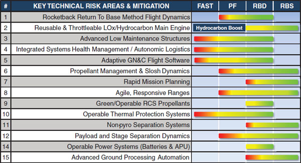
FIGURE 3.4 Sample risk mitigation strategy. SOURCE: Slater Voorhees, Lockheed Martin Corporation, “Reusable Booster System (RBS),” presentation to the committee, March 28, 2012. Approved for Public Release.
conditions above Mach 3 and subsequent return to the launch site, it was not clear what else the Pathfinder demonstration would achieve. Also, there was no description or discussion of the Pathfinder MPS design. For example, is it intended to use one ORSC engine, such as the existing NK-33? Or, would it just use an existing, off-the-shelf, available open-cycle engine such as Fastrac17 or a Falcon 1 Merlin? There was no discussion of which, if any, propulsion elements and associated information would be directly applicable to the RBS design.
The committee believes that developing a better definition of the goals and objectives of the Pathfinder program is important for two reasons. First, it is important to understand whether the cost is worth the investment. As stated above, there are important technical questions that can be answered in a Pathfinder program, but these questions will be answered only if the program is properly structured. Second, an understanding is needed of how the results of the Pathfinder program can be used to decide whether it is worthwhile to proceed to the next step, the RBD. So, decision gate criteria should be developed to enable a decision on what to do next after a successful Pathfinder demonstration.
The development of RBS capabilities will challenge many of the limits of state-of-the-art capabilities in such disciplines as propulsion, aerothermodynamics, controls, structures, health monitoring and sensing. The Air Force plans to develop the technologies needed to achieve the goals for the RBS program in phases. An example of a program that follows this approach is provided in Figure 3.4, taken from Lockheed Martin’s presentation18 to the committee. In the figure, the technology development is shown to occur under the following programs: the
_____________
17 Fastrac was a LO2/RP-1 60,000 lbf gas-generator cycle engine that delivers a vacuum Isp of approximately 280 s. It was developed by NASA Marshall Space Flight Center (MSFC) and intended for flight application on the X-34 program by Orbital Sciences, but the program was cancelled and the engine inventory was placed in storage at MSFC.
18 S. Voorhees, Lockheed Martin, “Reusable Booster System (RBS),” presentation to the Committee for the Reusable Booster System: Review and Assessment, February 28, 2012. Approved for Public Release.
Future Responsive Access to Space Technologies (FAST), Pathfinder, the RBD, and RBS full-scale development. (Note that the AFRL-funded FAST program has been completed.) This phased technology development suggests that the maturation of the HCB, Advanced Low Maintenance Structures, IVHM, adaptive AG&C flight software and operable thermal protection systems, which was initiated under the FAST program and will need to continue under subsequent programs (e.g., Pathfinder, RBD, and RBS). The Pathfinder program will also initiate development of capabilities for executing the rocketback RTLS maneuver and for handling propellants management and slosh dynamics, agile responsive ranges and payload separation dynamics. The RBD program will continue the development of the above listed technologies and initiate development of capabilities for rapid mission planning, green/operable RCS propellants, operable power systems for batteries and APU, non-pyro separation, and advanced ground processing automation. The cost benefits of these technologies will be quantified during testing of the full-scale RBS Y-vehicles.
Attaining the goals of the RBS program critically depends on successful demonstration of the relatively large number of widely varying technologies and capabilities. However, it is often difficult to assess the challenges associated with overcoming certain technical barriers until these are studied and characterized over a period of time. Having said this, it seems at the outset that executing the RTLS rocketback maneuver without damaging the booster and ORSC engines will be critical to the success of this program because such a maneuver has never been demonstrated at the scale of the RBS. Executing the RTLS rocketback maneuver will be challenging because it will depend on developing capabilities for considerable hydrocarbon rocket thrust throttling, handling the sloshing and dynamics of the propellants, controlling complex aerodynamics that may involve interactions of the rocket exhaust plume with the system’s aerodynamics, and providing adequate thermal protection.
Additionally, the attainment of “reusability,” which is critical to achieving the expected cost savings, will require development of a reliable IVHM system. Such an IVHM system has to be capable of monitoring the health of critical components of the reusable part of the system. To be effective, the development of the IVHM would logically be undertaken in concert with the development of other system components such as the structure and the propulsion system. However, it is not clear at this point how this will be accomplished if the RBS is to employ legacy propulsion systems such as proposed with the use of the AJ-26.
Finally, development of an adaptive guidance and control system will be critical to the operation of the unmanned, autonomous reusable booster that will need to operate in a complex environment with inherent uncertainties in vehicle performance.


