
At the Pueblo Chemical Agent Destruction Pilot Plant (PCAPP), after the munitions have been robotically opened, the mustard agent will be destroyed by chemical hydrolysis with hot water (194°F), followed by addition of caustic to raise the pH to between 10 and 13. These processes yield a waste called “hydrolysate.” The mustard agent’s complete destruction is verified by sampling and analyzing the hydrolysate after neutralization. The hydrolysate is no longer chemical warfare material; the process also ensures that the product is not flammable. The hydrolysate will then be mineralized to water, carbon dioxide, and salts in the subsequent biotreatment step, using biodegradation and water recovery. This chapter provides an overview of the basic processes that will be used at PCAPP to destroy the munitions and mustard agent and provides information on the composition and concentrations of the hydrolysate. This is followed by descriptions of the downstream processing units, including the immobilized cell bioreactors (ICBs) and the brine reduction system (BRS).
BRIEF DESCRIPTION OF THE PCAPP PROCESS
Details of the process planned for destruction of the mustard agent at the Pueblo Chemical Depot can be found in prior National Research Council (NRC) reports (NRC, 2008, 2013). Only a brief overview is provided here, because the process design is not the focus of this report. A block diagram of the PCAPP process is presented in Figure 2-1. The approach to mustard agent destruction is divided into two broad phases. The first phase involves munitions processing and agent neutralization, which generates a secondary wastewater stream, called hydrolysate, that requires subsequent treatment. The steps in this first phase, which comprise the box labeled Munitions Processing and Agent Neutralization in Figure 2-1, include the following:
- Remove munitions from the pallets.
- Separate the propellant from the projectile.
- Remove bursters at the linear projectile/mortar disassembly machine.
- Send uncontaminated bursters and propellant offsite for destruction.
- Wash out the mustard agent from the projectile bodies in the munition washout station (MWS) with a high-pressure water stream. The projectile bodies are then thermally decontaminated. The clean projectile bodies are shipped offsite for disposal.
- Send mustard and washout water to the agent hydrolysis reactors, where the agent is hydrolyzed with hot water at 194°F. Caustic is added to raise the pH above 10 to prevent any reversible reactions back to mustard agent. The resulting product is called the agent hydrolysate.
- Analyze the hydrolysate to verify that the mustard concentration is below 20 ppb and the distilled mustard (HT) concentration is below 200 ppb. The hydrolysate is then sent to one of three storage tanks. Each tank has a volume of 285,750 gal and provides up to 10 days of storage time, so the total storage period for hydrolysate is up to 30 days.
- If the munition is leaking or contaminated with agent, the whole munition is destroyed by detonation using explosive destruction technology at an onsite facility separate from PCAPP.
The main chemical in the hydrolysate resulting from the mustard agent neutralization process is thiodiglycol (TDG). The liquid hydrolysate containing TDG will be treated in the second phase of the process by using immobilized cell bioreactors (ICBs) in the biotreatment area (BTA). The steps in this second phase include the following:
- Transfer and treat the hydrolysate in the ICBs, where the main component, TDG, will be mineralized by the microorganisms under aerobic conditions. The hydrolysate is diluted and neutralized with H2SO4 in
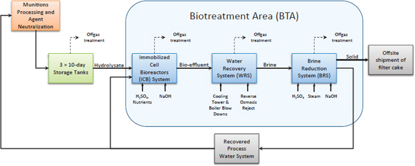
FIGURE 2-1 PCAPP biotreatment area process diagram. SOURCE: Adapted from Don Guzzetti, start-up field supervisor, PCAPP, and Dave DeLesdernier, support, Battelle, “Biotreatment Area Risk Reduction & Mitigation,” presentation to the committee on July 29, 2014.
- the ICB’s feed tanks prior to entering the ICBs. This step is represented by the box labeled Immobilized Cell Bioreactors System in Figure 2-1. A removal efficiency of at least 95 percent of the influent TDG is the treatment goal for the ICBs. There is flexibility in this value, because failure to attain this TDG removal efficiency does not automatically trigger offsite disposal, as described more fully in Chapter 7 (section Impacts If ICB Systems Underperform or Do Not Perform).
- The liquid effluent from the ICBs goes to the water recovery system (WRS), which is a storage and mixing tank, and is then processed by the BRS. This step is represented by the box labeled Water Recovery System in Figure 2-1.
- The BRS consists of an evaporator to yield a brine and biomass concentrate, which is sent to a crystallizer for further solids concentration. The water product from both the evaporator and crystallizer flows through a column of granular activated carbon for removal of trace organic constituents. The principal purpose of the BRS is to recover solids and generate a water stream that is of sufficient quality to become recycled process water. This step is represented by the box labeled Brine Reduction System in Figure 2-1.
- The salts and biomass solids recovered from the crystallizer are dewatered in a filter press and sent offsite for disposal.
- The recovered water is returned to a process water storage tank.
- The offgas from several of the treatment units can contain traces of toxic volatile substances and/or odorous compounds, as shown in Figure 2-1. For example, the volatile organic compounds (e.g., vinyl chloride) in the feed to the ICBs will be stripped from the bioreactor solution and appear in the offgas from the ICBs. These offgases are collected and passed through granular activated carbon adsorbers prior to release to the atmosphere.
PRODUCTION AND CHARACTERIZATION OF HYDROLYSATE
The hydrolysate will be generated in batches using two reactors, each having a working capacity of 3,600 gal. The maximum production rate of the liquid hydrolysate is expected to be 10,200 lb/hr.1 The peak liquid flow rate of hydrolysate to the three 10-day storage tanks is expected to be 19 gal/min, or 27,360 gal/day.
Through the Assembled Chemical Weapons Alternatives (ACWA) program, biodegradation testing of hydrolysate was conducted by Guelta and Fazekas-Carey in 2003. The test hydrolysate for the 2003 studies was generated from drained liquid agent and the solid heel material in 4.2-in. mortar rounds containing distilled mustard (HD) stored at the Pueblo Chemical Depot. The components and concentrations detected in the hydrolysate for these 2003 studies are given in Table 2-1. The Resource Conservaton and Recovery Act (RCRA) permit is another source for the composition of the PCAPP agent hydrolysate (third column in Table 2-1). The characterization information provided in Table 2-1 is considered representative of what will be encountered when the PCAPP facility begins processing munitions. The principal
________________
1 Bill Steedman, senior process engineer, PCAPP, “PCAPP Agent Treatment Process,” presentation to the committee on July 29, 2014.
TABLE 2-1 HD Hydrolysate Characterization from 2003 Biotreatment Testing and RCRA RD&D Permit Waste Analysis Plan (milligrams per liter unless otherwise noted)
| Component | Concentration from Guelta and Fazekas-Carey (2003) | Anticipated Agent Hydrolysate Composition |
| Thiodiglycol (TDG) | 17,537 | 52,250 |
| Dithiane | 2,093 |
1,370 |
| Thioxane |
47.9 |
N.R. |
| Chemical oxygen demand (COD) | 43,100 | N.R. |
| Total organic carbon (TOC) | 8,120 | N.R. |
| Percent TOC as TDG (%) |
84.9 |
N.R. |
| COD:TOC ratio |
5.31 |
N.R. |
| Sulfate | 84 | N.R. |
| Sulfur | 6,010 | N.R. |
| Total dissolved solids (TDS) | 28,000 | N.R. |
| Total suspended solids (TSS) | 1,000 |
8,676 |
| pH | 13 | 10 to 12 |
| Specific gravity | 1.03 g/mL | 1.066 g/mL |
| Aluminum |
1.99 |
N.R. |
| Ammonia | N.R. |
2.99 |
| Arsenic |
0.579 |
2.02 |
| Barium |
0.033 |
2.47 |
| Cadmium |
3.2 |
0.0 |
| Calcium |
10.9 |
N.R. |
| Chloride | 10,800 | N.R. |
| Chromium(VI) | N.R. |
0.90 |
| Chromium (total) | N.R. |
1.64 |
| Copper |
0.281 |
6.52 |
| Fluoride | N.R. |
0.54 |
| Iron | 520 | 2,160 |
| Lead |
3.69 |
1.43 |
| Magnesium |
5.74 |
N.R. |
| Mercury |
0.013 |
0.154 |
| Molybdenum |
0.065 |
N.R. |
| Nickel |
0.330 |
1.754 |
| Phosphorus |
0.456 |
N.R. |
| Potassium | 15.2 | N.R. |
| Silver |
5.73 |
N.R. |
| Sodium | 10,630 | N.R. |
| Zinc |
3.59 |
3.81 |
| 1,2,3-Trimethylbenzene | N.R. |
0.0 |
| 1,2,4-Trimethylbenzene | N.R. |
0.0 |
| 1,2-Dichloroethane | N.R. | 181 |
| 2-Butanone | N.R. |
2.56 |
| 2-Hexanone | N.R. |
6.20 |
| 4-Methyl-2-pentanone | N.R. |
7.30 |
| Acetone | N.R. |
6.29 |
| Acetonitrile | N.R. |
0.0 |
| Benzene | N.R. |
0.319 |
| Chloroform | N.R. |
0.319 |
| Diethyl ether | N.R. |
0.288 |
| Hexane | N.R. |
0.0 |
| Methylene chloride | N.R. |
1.31 |
| m- and p-Xylenes | N.R. |
0.07 |
| Naphthalene | N.R. |
0.038 |
| Tetrachloroethene | N.R. |
8.67 |
| Toluene | N.R. |
0.066 |
| Trichloroethene | N.R. |
1.52 |
| Vinyl chloride | N.R. | 11.9 |
| 2-Methylphenol | N.R. |
0.0 |
| 2-Nitrophenol | N.R. |
0.0 |
| 3- and 4-Methylphenol | N.R. |
0.0 |
| 1,4-Oxathiane | N.R. | 534 |
NOTE: N.R., Not reported.
SOURCE: PCAPP (2006), Table C-9. Concentrations in Table C-9 are based on the treatment of distilled mustard agent at the Aberdeen Chemical Agent Disposal Facility (ABCDF).
components of hydrolysate are TDG, other organic compounds (mainly dithiane and thioxane), suspended solids, and dissolved inorganic compounds (predominantly sodium chloride and iron salts). Many trace organic and inorganic compounds are also detected.
Another indicator for the character of the agent hydrolysate is obtained from the reported design parameters for the ICBs (Table 2-2). The plan calls for diluting the agent hydrolysate after it leaves one of the 10-day storage tanks, with the recycled process water in the ratio of one part hydrolysate to seven parts process water before it enters the feed tank to the ICBs. The dilution is required to maintain the influent TDG concentration at a level (7,000 mg/L) that results in nontoxic levels for the bacteria within the ICBs. The toxic threshold for TDG to the biomass is estimated to be 2,000 mg/L. This means that TDG concentrations must be maintained below 2,000 mg/L in the ICB units. The treatment goal (RCRA RD&D permit performance) is to remove at least 95 percent of the TDG in the ICBs,2 so that steady-state TDG biodegradation should keep the reactor contents below the toxic threshold concentration. Furthermore, the hydraulics within an ICB chamber approaches complete mix from the coarse bubble aeration system. This provides for significant dilution of the influent feed TDG concentration. It is expected that a feed TDG concentration of 7,000 mg/L or less can be supplied to the ICBs during steady-state operation to prevent toxicity to the bacteria from the TDG.
DESCRIPTION OF THE IMMOBILIZED CELL BIOREACTORS
The TDG and other compounds in the agent hydrolysate will be aerobically biodegraded in an ICB, where the biomass is attached to a carrier medium. The bioreactor system consists of 16 ICB units configured in four parallel modules with four units per module. Each ICB unit has a volume of about 42,000 gal and is divided into three chambers in series with volumes of 21,000 gal, 10,500 gal, and 10,500 gal, respectively. The hydrolysate feed to each ICB unit requires dilution (one part hydrolysate to seven parts process water) to achieve nontoxic levels of the TDG in the bioreactor. The expected hydraulic loading rates to each ICB unit are anticipated to vary between 4,800 and 9,700 gal/day (BPT, 2006), yielding an average hydraulic retention time of between 8.6 and 4.3 days, respectively. The ICBs are expected to remove at least 95 percent of the influent TDG.
Additional details of the physical layout and planned operation of the ICBs are provided in a recent NRC report (2013). The committee that prepared the 2013 report reviewed the bench and pilot-scale studies that evaluated biodegradation of TDG and the planned design and operating procedures for the ICBs. Several issues pertinent to the operation of the ICBs were identified that merit close attention, and the major ones are summarized in Table 2-3.
TABLE 2-2 Key Design Operating and Feed Characteristics for the Immobilized Cell Bioreactor Units
| Design Characteristic | Hydrolysate (total) | ICB Influent (per unit)a |
| Flow (gal/day) | 16,766 | 8,383 |
| Hydraulic retention time (days) | 4.98b | |
| Volume (gal) | 41,783 | |
| Concentration of TDG (mg/L) | 56,000 | 7,000 |
| Concentration of TSS (mg/L) | 8,000 | 1,000 |
| Concentration of COD (mg/L) | 120,000 | 15,000 |
| Concentration of TOC (mg/L) | 26,400 | 3,300 |
| Concentration of iron (mg/L) | 2,160 | 270 |
| Concentration of NaCl (mg/L) | 57,600 | 7,200 |
| pH | 10-13 | 7-8c |
a The ICB influent is diluted with process water (1:7), resulting in a total flow of 134,128 gal/day across 16 ICB units.
b This was calculated from the flow and volume shown.
c This will be maintained via acid production within the unit and caustic or acid addition as needed.
SOURCE: Paul Usinowicz, PCAPP technical advisor, and Yakup Nurdogan, PCAPP lead industrial wastewater treatment engineer, “Biotreatment Area (BTA) Cradle to Grave,” presentation to the committee on July 30, 2013, and NRC (2013).
DESCRIPTION OF THE BRINE REDUCTION SYSTEM
The BRS is designed to recover water from a number of sources within the PCAPP system, provide a recycle water stream for the process water needs of the facility, and allow the PCAPP system to achieve zero liquid discharge operation. The salts and biomass recovered from the crystallizer will be dewatered in a filter press and sent offsite for disposal as a solids residue. The feed for the BRS is sourced from the WRS, where a number of streams, including the effluent from the biotreatment system, are collected for feed to the BRS. For the purposes of this discussion the WRS, which is an aerated tank system, will be considered as part of the BRS. This section provides a simple description of the BRS. A more detailed description is available in previous reports (NRC, 2013; PCAPP, 2014).
The major equipment in the BRS consists of WRS tanks, an evaporator system, a crystallizer system, and a granular activated carbon system. The WRS tanks provide an equalized feed to the evaporator system, where the water stream is pretreated to remove carbon dioxide through acidification and aeration before concentrating the brine stream through water evaporation and distillation to recover water for recycle. The recovered water stream is processed through
________________
2 PCAPP, RCRA RD&D Stage III, Class 3, Permit Modification Request, Revision 0, November 2006, Appendix D, Waste Analysis Plan, C-2a(3) (d), p. C-11.
| Issue | Explanation |
| Toxicity | At elevated concentrations (>2,000 mg/L), TDG was observed to become inhibitory in a previous biodegradation test. Once the ICBs are in a steady state, the 1:8 dilution of the agent hydrolysate and treatment goal of at least 95 percent destruction of TDG should maintain TDG concentrations well below toxic concentrations in the ICBs. Toxic inhibition may be a concern during start-up and off-normal operation, especially if there is elevated loading of the TDG or periods with poor biodegradation of the TDG. |
| Inhibition by heavy metals | The hydrolysate contains some heavy metals that can exert antimicrobial properties, such as Ag and Cu. The levels of metals expected is not likely to be a major concern during steady-state biotreatment, but toxicity from heavy metals should be explored if performance of the ICBs is below expectations. |
| Inhibition by sulfide | The organic sulfur in TDG is converted to sulfate during the aerobic bio-oxidation of TDG. If the conditions in the bioreactor and biomass are not fully aerobic, anaerobic microniches may occur within the immobilized biomass and facilitate the reduction of sulfate to sulfide. Sulfide can be toxic to bacteria at concentrations >100 mg/L. Sulfide toxicity can be minimized with sufficient aeration and development of fully aerobic biofilms. |
| pH | The TDG biodegradation tests suggest an optimum pH range of 7 to 8 for the ICBs. The hydrolysate with high pH is first neutralized with H2SO4 in the feed tank prior to entering the ICBs. TDG bio-oxidation within the ICBs generates sulfuric acid. Therefore, pH control is essential, and it may be challenging to maintain the proper pH. |
| Temperature | The past biodegradation testing with TDG observed stable performance in the temperature range of 46°F to 95oF. Steam injection can be used to heat the ICBs, but there are no provisions for cooling the ICBs. It is not known if summertime heat and solar load can cause the temperatures in the ICBs to exceed the optimum range. |
| Solids buildup | The feed hydrolysate to the ICBs is likely to contain significant TSS. The feed also contains iron, and phosphate is added as a nutrient. These inorganics are likely to precipitate and produce inorganic solids. Biomass, a third important solid in the ICBs, may build up excessively and alter the hydraulic characteristics. Periodic sloughing of the biomass could contribute to intermittent releases of large quantities of biomass solids into the effluent from the ICBs, resulting in a higher solids loading to the BRS. |
| Oxygen demand and flux issues | Air will be supplied to the ICBs via coarse diffusers to provide oxygen for the biodegradation of TDG. The air supply is evenly distributed throughout the three chambers, with all of the TDG loading entering in the first chamber. Consequently, the demand for oxygen in the first chamber may exceed supply, resulting in lack of oxygen within the biomass/foam medium. |
| Start-up issues | Given the factors identified above with the unique and complex hydrolysate feed, the start-up of the ICBs is likely to be a critical period, especially considering the potential for toxic inhibition and solids buildup and challenges with the air supply and maintenance of the optimum pH. |
| Characterization and monitoring | Little is known about the composition and variability of the ICB effluent, especially in terms of residual nonbiodegradable compounds and soluble microbial products. Similarly, little is known about the residual volatile organic compounds in the offgas. During initial operation, the composition and characteristics of the ICB effluent and offgas should be monitored to anticipate potential long-term concerns for downstream processing. For example, the presence of uncharacterized compounds in the hydrolysate feed to the ICBs may build up in the recycled process water. |
SOURCE: NRC (2013).
TABLE 2-4 Issues Identified in a Review of the Brine Reduction System
| Issue | Explanation |
| Carbon adsorbers meeting permit requirements with acceptable pressure drop | There is uncertainty about the composition of the water leaving the carbon adsorbers and whether there will be plugging that leads to higher-than-anticipated pressure drop across the bed. It may be necessary to replace the carbon beds and backwash them more frequently than currently anticipated. |
| Quality of distillate from the crystallizer | There is uncertainty about the concentrations of the organic compounds in the distillate from the crystallizer. If they are too high, it may be necessary to improve de-entrainment in the crystallizer. |
| Too much water in filter cake | The presence of organic matter in the filter cake may make it very difficult to reach the desired solids content. Methods for additional dewatering or alternate disposal options would then be needed. |
| No prior full-scale testing data available | The amounts and identities of all of the components in the BRS feed stream are not known. PCAPP needs to monitor the BRS feed and effluent streams during hydrolysate treatment and be prepared for unanticipated components or concentrations. |
| Acid hydrolysis of biomass | If biomass components hydrolyze during acid treatment, there could be operational problems downstream. Installing a clarifier between the ICBs and the BRS is a potential solution. |
SOURCE: NRC (2013).
carbon beds and then forwarded to the process water system. The concentrated brine is further processed in the crystallizer system. As with the evaporator system, the distillate water is fed to carbon adsorption and then to the process water system. The concentrated brine slurry is sent to a belt filter system. The filtrate from the belt filter press is recycled to the front of the crystallizer. The filter cake from the filter system is packaged and sent offsite for disposal.
A number of risk reduction and minimization studies are planned prior to the start-up of munitions processing at PCAPP, to be conducted in tandem with systemization. The most significant of these tests is the operation of the units with feed from the TDG surrogate testing of the ICBs. This test will provide a feed that mimics the expected operation as closely as possible in that it will have a brine feed with a salt and biosolid content that will be similar to what is expected during operation. In that respect it is foreseen that it will be possible to get an early indication of the water quality, fouling characteristics, and other processing capabilities of the operating units.
Just as Table 2-3 identifies issues that may be of concern with the ICBs, Table 2-4 identifies such issues for the BRS. These items are taken from the 2013 NRC report.
BPT (Bechtel Pueblo Team). 2006. System Design Description (SDD) for Biotreatment System No. B09. Pueblo, Colo.: Bechtel.
Guelta, M.A., and L. Fazekas-Carey. 2003. Biodegradation of Hydrolyzed Mustard from an Assembled Chemical Weapons Assessment (ACWA) Projectile Washout Study. ECBC-TR-291. Aberdeen Proving Ground, Md.: Edgewood Chemical Biological Center.
NRC (National Research Council). 2008. Review of Secondary Waste Disposal Planning for the Blue Grass and Pueblo Chemical Agent Destruction Pilot Plants. Washington, D.C.: The National Academies Press.
NRC. 2013. Review of Biotreatment, Water Recovery, and Brine Reduction Systems for the Pueblo Chemical Agent Destruction Pilot Plant. Washington, D.C.: The National Academies Press.
PCAPP (Pueblo Chemical Agent Destruction Pilot Plant). 2006. PCAPP RCRA RD&D Stage III, Class 3, Permit Modification Request, Revision 0. Attachment D, Waste Analysis Plan. Pueblo, Colo.: Pueblo Chemical Agent Destruction Pilot Plant.
PCAPP. 2008. RCRA Permit Attachment D Waste Analysis Plan, Modification #6, Pueblo Chemical Agent Destruction Pilot Plant.
PCAPP. 2014. White Paper: Bio-Treatment Area Risk Reduction and Mitigation. 24852-30H-BTA-V0001. Pueblo, Colo.: Pueblo Chemical Agent Destruction Pilot Plant.


