3
Flow and Transport: Underlying Processes
Chapter 2 reviewed the physical and structural properties of fractured rock that are relevant to subsurface contaminant fate and transport. This chapter reviews processes that affect fate and transport over different relevant timescales, including hydrologic, thermal, chemical, biological, and mechanical processes. These properties and processes form the basis for the conceptual and computational models used in the analysis of fractured rock sites discussed in Chapter 4.
ADVECTION AND DISPERSION
Advection, dispersion, and diffusion in fractured rock are the key processes that control the fate and transport of contaminants in fracture networks and contaminant migration into and out of the rock matrix. The underlying physics of these processes are the same in both soils and fractured media; however, their relative impacts and the degree of control of the solid structure (granular versus cemented) are significantly different when considering fractured rock settings. Some important additional considerations unique to fractured rock are discussed in the following sections. For the most part, the following processes are invariant with depth below ground surface.
Impacts of Transmissivity and Flow Focusing on Advection
As discussed in Chapter 2, groundwater flow in individual fractures is controlled by the geometry and connectivity of those fractures. Advective transport relies on the bulk motion of a fluid (i.e., groundwater) driven by the total energy gradient. Contaminants (which can include dissolved species, suspended solids, bacteria or viruses, and colloids) are transported by advection in flowing groundwater. Fractures are generally the primary paths for advective flow (Birkholzer et al., 1993), although the rock matrix may play an important role in more permeable rocks such as some sandstones.
Transmissivity is defined as the volume of fluid per unit time (flow) per unit width for a hydraulic gradient equal to 1.0. It is a common descriptor of the hydraulic property of fractures and varies by many orders of magnitude among fractures. The analysis and discussion in Box 3.1 demonstrates that relatively few of the fracture population (i.e., less than 10 percent) transports more than 90 percent of the total advective flow in most situations.
The identification of flow-controlling fractures is crucial to the development of a reasonable conceptual model for fractured rock sites; hence, their identification is also a critical step in the decision-making process (see Chapter 7). In many fractured rock settings, advection is the predominant transport process, and thus a rigorous, quantitative discernment of highly transmissive pathways is required. In most fractured rock settings, averaged or effective media properties (the approach applied in sediments) do not represent the discrete nature of advection appropriately, and discrete fracture models are needed (see Chapter 4). Project objectives and fracture size characteristics relative to the physical dimensions of the phenomenon or site of interest may require, however, that effective media properties be used to represent fluid flow and contaminant transport in fractured rock (see Chapter 6).
Structural Controls on Hydrodynamic Dispersion
Dispersion due to mechanical effects in flow pathways results from mixing at fracture intersections, fracture tortuosity (the length of the actual flow path relative to the linear distance between two points), aperture variability in a single fracture, transmissivity variation between fractures and ensuing velocity changes, and fracture interconnectivity. The effects of mixing/dilution in fractured rock due to structural controls (e.g., intersections, aperture variability) are much stronger than those due to similar controls in soils. Although dispersion occurs primarily in two dimensions (within the fracture plane), the effects are often observed in three dimensions because of interconnectivity. Representation of dispersion using classical dispersion tensor approaches
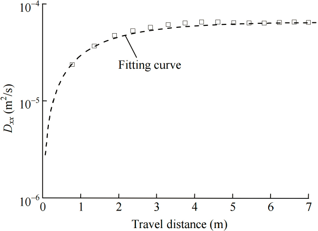
used in soils is not appropriate, but the concept of a three-dimensional assemblage of two-dimensional features should be considered. Hydrodynamic dispersion impacts residence times in fractured rock and is likely scale dependent (Berkowitz and Scher, 1995; Rubin and Buddemeier, 1996; Dagan and Neuman, 1997; Berkowitz, 2002; Neuman, 2005). Figure 3.1 shows that hydrodynamic dispersion is most pronounced near sources and plateaus quickly once the scale of observation approaches that of the scale of the fractures. This behavior contrasts the classical assumption of a continuous increase in dispersion with increasing travel length used in granular media. Recent work challenges the classic paradigm of advection in soils (Payne et al., 2008; Hadley and Newell, 2014) and is more in line with the mechanistic description of fractured rock.
The prevalence of flow focusing and structural controls on dispersion in fractured rocks (as compared to sediments) is an inherent and critical characteristic in fractured rock masses and has a pronounced effect on all flow-related problems, and equivalent continuum soil-derived approaches need to be used with caution and appropriate qualifications.
Dispersion and Transport in Cyclic Flow
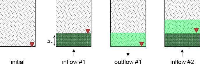
Another transport mechanism results from the combination of hydrodynamic dispersion and cyclic fluid flow whereby inflow-outflow cycles (with zero remnant invasion at the end of the cycle) combine with pore-scale mixing to render effective transport (see Figure 3.2): even though the cumulative fluid flow volume is null at the end of each inflow-outflow cycle, solute is effectively transported into the medium (Knothe Tate et al., 1998; Wang et al., 2000; Goldstein and Santamarina, 2004; Claria et al., 2012). The more dominant structural controls in fractured rock make this phenomenon potentially more important than in soils. Efficient transport in cyclic fluid flow can affect natural systems (such as nearshore saltwater intrusion due to tidal action) and can be used to engineer treatment strategies where monotonic advective regimes cannot be established but where inflow-outflow pumping cycles can be imposed.
HYDRO-MECHANICAL COUPLING
The fluid pressure field present in geologic systems affects the effective stress field, and changes in effective stress affect fracture apertures, which in turn modify the fluid pressure field. These processes are depth invariant. The greater the effective compressive stress, the smaller the aperture. For example, if a well is pumped, the water level in the well declines, the fluid pressure in the rock is reduced, the effective compressive stress increases, apertures close, and transmissivities decrease (Segura and Carol, 2008). The significance of this trend depends greatly on the compressibility of the fractured rock.
The reverse situation is of great importance: if a well is pressurized, hydro-mechanical coupling can lead to the localized opening of preexisting discontinuities in the fractured rock (Zoback et al., 1977; Warpinski and Teufel, 1987; Beugelsdijk et al., 2000; Chuprakov et al., 2011; Fisher and Warpinski, 2011). The ensuing distortion band dilation of the surrounding medium can explain the high-flow efficiencies observed in prestructured media, such as the recovery of gas from shales following hydraulic fracture enhancement (Dusseault, 2011). Hydro-mechanical coupling gains relevance under high pumping regimes, such as in engineered hydraulic fracturing.
CHEMICAL PROCESSES: DIFFUSION AND REACTION
Although fractures dominate advective transport in most fractured rock, the volume of void space in the rock matrix is, in most cases, orders of magnitude greater than the volume of void space in the fractures. This skewed volume ratio results in the matrix accounting for the majority of the contaminant storage in fractured rock settings. Under these circumstances, diffusive contaminant transport between the matrix and the fractures exerts considerable control on the spatial distribution of the contaminants, as well as timescales of transport.
Diffusive Matrix-Fracture Coupling
Chemical constituents dissolved in groundwater can diffuse between fluid-filled rock matrix and fractures as a result of random molecular motion, the direction of concentration gradients, and the tortuosity of the pore space. Diffusion is almost unaffected by pore size (first order approximation); hence, diffusion takes place within and between the matrix and fracture porosities (e.g., Neretnieks, 1980; Maloszewski and Zuber, 1993). The relative rates of advective and diffusive transport are dependent on fracture and matrix properties (see Box 3.2). In most cases, advection
is the main transport mechanisms along fractures, while diffusive transport prevails in the matrix and is orthogonal to the fracture plane. The relative timescales for matrix diffusion and advective transports along fractures have a critical role in the development of site conceptual models, in the design of site investigations and in the selection of remediation strategies for fractured rock systems.
Fracture-Matrix Diffusive Interaction During Contaminant Advection
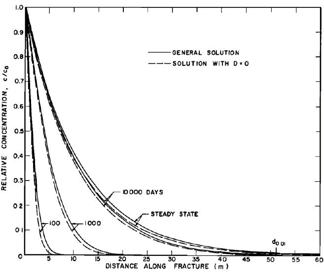
The diffusion of contaminant into the matrix during advection along fractures results in contaminant mass retardation as contaminant is “lost” from the advection-dominated fractures into the matrix (Golubev and Garibyants, 1971; Tang et al., 1981; Sudicky and Frind, 1982; VanderKwaak and Sudicky, 1996). Figure 3.3 demonstrates that actual contaminant velocities can be significantly lower than the advective velocity within the fracture.
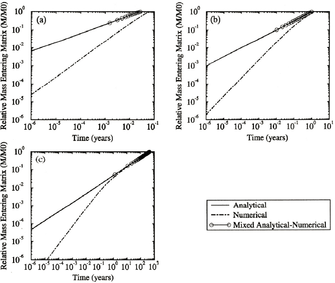
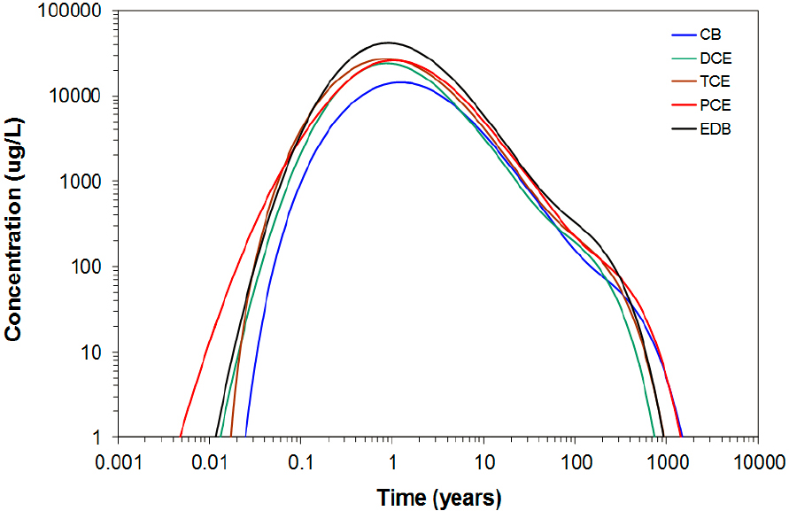
The end result of the rapid diffusion of contaminant into the rock matrix is that a significant amount of contaminant will reside within the matrix in a relatively short timeframe. The relative percentage of chemical contaminants in the matrix versus total contaminant for different fractured systems (where contaminant enters entirely as dissolved compounds in fractures) is shown in Figure 3.4 (VanderKwaak and Sudicky, 1996). In this example, most of the chemical mass is in the matrix within 1 year of it entering a fractured rock system. Understanding the importance of matrix diffusion and its timescales are critical for planning site investigations in fractured rock systems.
Matrix diffusion takes place at all depths. Given the geothermal gradient, analyses need to incorporate increasing diffusion rates and decreasing fluid viscosities with increasing temperatures. Both diffusive and advective processes are also affected by the tendency of deep aquifer rocks to have lower matrix porosities and narrower fracture apertures.
Delayed Release: Back Diffusion
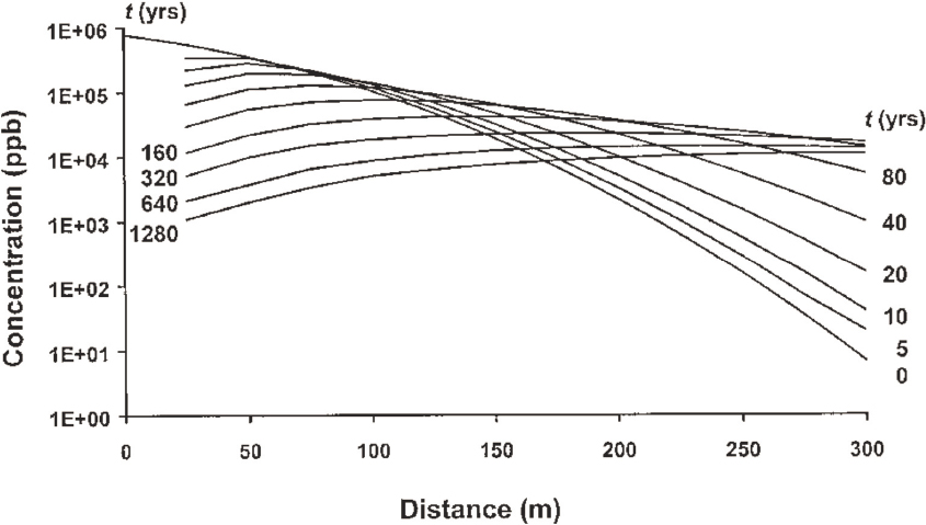
The rock matrix porosity acts as a reservoir that can sustain long-term release of contaminants back into fractures through reverse or back diffusion (Parker et al., 1994; Reynolds and Kueper, 2002; Lipson et al., 2005). This back diffusion reflects the same diffusive process that occurred during the original contaminant invasion of the matrix. High concentration gradients during advection lead to a fast increase in contaminant concentration and storage in the matrix (and the non-conductive fractures within the rock matrix). Gradually lower concentration gradients (which may occur during remediation activities) result in remediation times that can exceed hundreds or thousands of years (Reynolds and Kueper, 2002; Lipson et al., 2005; see Figure 3.5).
Time-dependent matrix back diffusion effects on plumes are not well characterized in complex fracture networks; yet, plume attenuation in fractured rock systems is critically important for decisions related to risks that plumes pose to human and ecological health (Sudicky and Frind, 1982; McKay et al., 1993; Lipson et al., 2005). The complexity of fracture networks greatly hinders the development of quantitative relationships that could estimate back diffusion contaminant mass loading to systems.
Reactive Fluid Transport
Geochemical reactions within fractures can exacerbate flow heterogeneity and may lead to the formation of pipes, channels, and caverns (Tsang and Tsang, 1989; Dagan and Cvetkovic, 1996; Cvetkovic et al., 1999). As described in Chapter 2, some dissolved contaminants may precipitate out of solution, plug flow paths, and force transport through different pore spaces. The opposite can also occur when dissolution of minerals by flowing groundwater opens up previously plugged pore spaces. In addition, biological processes can alter fluid transport by causing precipitation of chemicals or biomass growth and cause a reduction in the area available for fluid flow. Recent publications provide experimental evidence (Fredd and Fogler, 1998, 1999; Singurindy and Berkowitz, 2005; Yasuhara et al., 2006; Noiriel et al., 2007; Elkhoury et al., 2013; Ruiz-Agudo et al., 2014) and complementary numerical studies (Chen and Doolen, 1998; Chaudhuri et al., 2008; Szymczak and Ladd, 2009; Chaudhuri et al., 2012; Ameli et al., 2014) relevant to fractures and fracture networks.
Geochemical reactions, advective contaminant transport, and diffusive transport rates control the evolving topology of dissolution (Steefel and Lichtner, 1994; Szymczak and Ladd, 2013). Discerning the relationships between the reaction rates and advective and diffusive transport rates guides the selection of the scale at which reactions must be incorporated into a site conceptual model. The probability of localized dissolution increases in settings with high reaction rates in advection-dominant transport (see Box 3.3). The formation of a dissolution feature alters the flow
regime, and other dissolution features will not form nearby (i.e., an exclusion distance between dissolution channels emerges). Localized dissolution channels extend the zone of high fluid pressure from the fracture inlet into the rock mass and lower the effective stress in the fractured rock mass. Eventually, large-scale instabilities may follow.
Chemical re-precipitation within the rock mass often complements dissolution (Dobson et al., 2003). Precipitated species may be the same as those dissolved upstream (e.g., frequent examples in carbonates), or selective precipitation-leakage results in other mineral formation (e.g., clay minerals). Fracture-scale dissolution and re-precipitation reactions can have pronounced macro-scale
effects. The potential for reactive fluid transport, therefore, should be considered in conceptual model development.
The long-term, large-scale projects envisioned for carbon capture and storage emphasize the need to understand and model carbon dioxide (CO2) storage capacity and the behavior of CO2 as it migrates through the reservoir along various pathways. Critical issues regarding fluid flow in reservoirs deeper than 1 kilometer have been identified through work at long-term CO2 storage sites such as the Sleipner field offshore Norway. Eiken et al. (2011) suggest the need to understand and model combined diffusion-convective mechanisms and fluid movement and to understand the mechanisms (such as diffusion, dilution, buoyancy forces, and capillary trapping) occurring when supercritical CO2 is injected in the reservoir.
BIOLOGICAL PROCESSES
Microorganisms inhabit almost every environmental niche in the biosphere, including shallow and deep fractured rock environments. Within these environmental niches, they form complex communities that can act as catalysts for a wide range of chemical reactions, including nucleation of gas bubbles that change water saturation; precipitation of minerals that cement fractures; dissolution of minerals that widen fractures; degradation of toxic organic contaminants; and formation of biofilms that hinder fluid flow and lead to clogging (Baveye and Valocchi, 1989; Kindred and Celia, 1989; Taylor and Jaffe, 1990a,b; Taylor et al., 1990; Clement et al., 1996; Ehrlich, 1999; Ross et al., 2001; Wagner et al., 2013).
Biological Rock Mass Properties: Conditions for Life
Life requires sufficient space, water, nutrients, energy, and adequate environmental conditions to flourish in rock masses. The presence and health of microbes in the subsurface generally is constrained by pore diameter (e.g., Fredrickson et al., 1997; Rebata-Landa and Santamarina, 2006; Bartlett et al., 2010). The nominal size of microorganisms is about 1 micrometer (see histogram of identified bacterial and archaeal cells versus cell size in Figure 3.6). Consequently, microbial activity should be anticipated in most fractures, even at depths in excess of hundreds of meters. However, the presence of life in the pores within the rock matrix may be limited by the absence of pores greater than or equal to 1 micrometer (Phadnis and Santamarina, 2011). Rocks such as shales, carbonates, evaporites, and granites often have mean pore sizes less than the nominal 1 micrometer cutoff (see Table 3.1).
The activities of microbial communities in fractured rocks can exert significant effects on both physical and geochemical characteristics and can have a critical role in natural attenuation. The potential role and importance of microorganisms on natural attenuation in fractured rock environments remain poorly recognized, even at a theoretical level within the research community. Furthermore, although some techniques are used currently to quantify rates of natural attenuation via biological processes in porous media (e.g., Illman and Alvarez, 2009), there exists almost no practical guideline to estimate those rates at fractured rock sites.
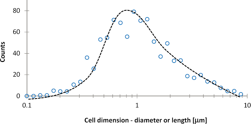
TABLE 3.1 Hydraulic Conductivity and Pore Diameters for Different Rock Types
| Rock | Hydraulic Conductivity (m/s)a | Pore Diameters (µm) | Reference | ||
|---|---|---|---|---|---|
| min. | med. | max. | |||
| Dolostone | 10–5.5 to 10–9 | − | 10.17 | − | Tanguay and Friedman, 2001 |
| Limestone | 10–5.5 to 10–9 | − | 31.5 | − | Laine et al., 2008 |
| Sandstone | 10–5.5 to 10–10 | 5 | − | 100 | Verges et al., 2011 |
| Shale | 10–9 to 10–13 | 0.005 | 0.1 | 0.75 | Loucks et al., 2009 |
| Unfractured Igneous Rocks | 10–9 to 10–14 | < 0.0038 | 0.413 | 80 | Mosquera et al., 2000b; Dultz_et al., 2013 |
a Hydraulic conductivity data from Freeze and Cherry (1979).
b Unfractured igneous rock pore diameter data are from granite rock samples.
Although biodegradation within the primary porosity of the rock matrix has been hypothesized as a natural attenuation mechanism that may reduce back diffusion loading to fractures, little is known about the presence, health, or activity of microbial communities in rock matrices.
Common Bio-Mediated Geochemical Cycles
Microbial communities can participate in the biogeochemical cycling of many elements, including carbon, nitrogen, sulfur, and numerous metals (Taylor and Jaffe, 1990a; Clement et al., 1996; Krumholz et al., 1997; Ehrlich, 1999; Geller et al., 2000; Ross et al., 2001; Wagner et al., 2013). For example,
- Solid phase ferric iron oxy-hydroxides can be mobilized to soluble ferrous iron form by iron reducing bacteria. This reaction generally requires the presence of an electron donor such as hydrogen or organic carbon.
- Microbial communities also can reduce soluble sulfate to sulfide that readily forms precipitates with cations; this important biogeochemical process affects flow through fractured media.
- Microbial archaea (methanogens) reduce CO2 to methane and bacterial acetogens reduce CO2 to organic acetate using hydrogen as an electron donor. High methane concentrations can result in the formation of bubbles that may also affect fluid flow.
Consequently, when groundwater transports compounds such as iron, manganese, sulfur, and CO2 from suboxic to oxic environments or vice versa, chemolithotrophic organisms1 can flourish, oxidizing or reducing dissolved forms to generate less soluble forms that can become clogging precipitates, dissolving insoluble forms to widen fractures, and generating gases that become bubbles. The geochemical environment within both fractures and matrix affects the potential for biological reactions. Analyses need to consider spatial and temporal variations in geochemistry, particularly at shallow depths where recharge and anthropogenic impacts are probable.
MIXED-FLUID CONDITIONS
Mixed-phase fluid conditions are common in fractured rock; examples range from vapor-water conditions in the vadose zone and deep geothermal reservoirs, to water-organics phases in contaminated sites and oil reservoirs, to vapor-liquid conditions that emerge during thermal and bio-mediated remediation strategies. In particular, many common organic contaminants exhibit very low miscibility in water (e.g., non-aqueous phase liquids [NAPLs]) and exist as a separate phase to water, as described in Chapter 1. Other contaminants that are lighter than water, such as light NAPLs (LNAPLs), released at or near land surface impact the water quality in fractured rock, particularly where there is little or no soil cover between the ground surface and the fractured rock. Because LNAPLs are lighter than groundwater, they infiltrate the vadose zone, driven by the fluid pressure in the LNAPL body and the effects of gravity. Furthermore, LNAPLs can be found up to several meters below the water table in systems subjected to water table fluctuations, or when a shallower LNAPL pool above the water table drives the localized LNAPL invasion into fractures and macropores (Adamski et al., 2005). On the other hand, when injected into water or brine-saturated formations at depth, LNAPLs will float and pool against seal layers, laterally restrained by geometric traps or by capillarity—the same behavior that occurs in the injection of CO2 for geologic storage.
Dense NAPLs (DNAPLs) such as trichloroethylene (TCE) have higher density and often lower viscosity than water. DNAPLs tend to migrate downward through the vadose zone, reach the water table, and displace water in the fractures (Kueper and McWhorter, 1991; Kueper et al., 1993). DNAPLs have the potential to migrate to great depths in fractured rock environments, and vertical migration is a critical part of understanding a fractured rock site impacted by DNAPLs.
Under these mixed fluid (or multi-phase) conditions, the interfacial tension at the contact between the two fluids will sustain a pressure difference between them (capillary pressure) that is inversely proportional to the curvature of the interface. When present in fractures, the curvature of the interface must be such that the interface can exist within the fracture; therefore, fracture aperture controls capillary pressure and the distribution and invasion potential of an immiscible phase.
NAPLs behave similarly to air in the subsurface: an air bubble can only invade a water-saturated porous material if the interface between water and air is forced into the porous material. Similarly, NAPL can only penetrate a fracture if the capillary pressure is great enough to deform the interface to the scale of the aperture. Once within the fracture, migration will occur along the
___________________
1 Chemolithotrophic organisms are those that use reduced inorganic compounds for energy.
path of least resistance (typically, the largest aperture pathway) and can stall if aperture sizes decrease to the point where the available capillary pressure cannot deform the interface to the required degree. Once within a fracture, NAPL will only penetrate the surrounding matrix pores if the pore size is large enough, as will be the case in many sandstones. Box 3.4 demonstrates the interplay between the physics of capillarity (determined by interacting fluids and the mineral substrate) and the geometric characteristics of fractures. It should be recognized, however, that NAPLs can dissolve in water to levels that are orders of magnitude above regulatory criteria. For example, TCE, one of the most ubiquitous organic contaminants found in the United States, has a solubility in water of approximately 1,000 mg/L (e.g., Russell et al., 1992) and a regulatory limit of approximately 0.005 mg/L. Thus, even if TCE is not found as a separate phase in the rock matrix, it may be present in the rock matrix at concentrations that are a risk to human and ecological health.
The relationships presented in Box 3.4 lead to the following general observations related to mixed fluid conditions in fractured rock masses:
- Capillary forces
- Affect contaminant invasion; variations in fracture aperture and matrix pore size result in a complex contaminant distribution in fractured rocks.
- Have a secondary role in the mechanical behavior of fractured rock masses unless the pore size, d, is sufficiently small so that capillary suction approaches the overburden stress σ; from Laplace’s equation (Equation a in Box 3.4), d ≤ 2, Ts/σ.
- Affect the displacement of fines in fractures subjected to mixed-fluid conditions, as fines are subjected to gravity (Archimedes buoyant weight), electrostatic forces (van der Waals and double layer repulsion as in DLVO theory), Stokes drag, and capillary forces (Sarkar and Sharma, 1990; Santamarina, 2002; Weisbrod et al., 2002).
- A non-wetting fluid (i.e., NAPL) will advance along fractures and will not likely penetrate into small pores in the rock matrix as a separate phase. Thus, NAPL storage will take place primarily in fracture porosity, although, as mentioned previously, the NAPL may have dissolved and is present in water contained in the rock matrix at concentrations not exceeding the solubility limit in water.
- Migration is not necessarily regular as a stable front; indeed, common field conditions lead to viscous fingering (high contrast in fluid viscosity) or capillary fingering, as shown in Figure B in Box 3.4.
- Under constant capillary pressure, an invading non-wetting fluid (i.e., fluid A in Box 3.4) will migrate along the wider interconnected regions of a fracture; hence, the rock matrix will retain a high saturation of the wetting fluid (i.e., fluid B in Box 3.4) even after the non-wetting fluid percolates across the entire rock mass (i.e., breakthrough).
- After invasion, buoyancy and capillarity define fluid distribution under equilibrium conditions.
- In smaller pores or narrower aperture fractures, viscous forces caused by advective flow (natural or pumping-induced) may not overcome capillary forces and contaminants will remain “capillary trapped” (this is termed “residual” NAPL).
Characterization and simulation of two-phase flow in fractured rock requires an understanding of the capillary pressure-saturation and relative permeability-saturation relationships in both the fractures and matrix. Unlike single-phase flow, the geometry of the phase boundary controls migration to a large extent. Nicholl et al. (1994) performed experiments in rough-walled fracture analogues and determined that the two-dimensional nature of the fracture (as opposed to the three-dimensional nature of the matrix and porous media) increased the importance of phase interference and trapping phenomena. The role of fracture-matrix interaction in an air-water system has been examined at a small scale (on the order of tens of centimeters) by many researchers, a summary of which can be found in Sakaki (2005). Gas-water flow in fracture networks was examined numerically by Glass et al. (2003), and the critical role of fracture intersections on the migration pathways was identified, as well as the capillary relationships. The scale of controlling phenomena in two-phase flow in fractured rock (cm) is such that explicit consideration is often not possible, and scaling or averaging approaches must be used. A mature body of work exists on scaling techniques, as well as quantification methods and parameterization approaches (e.g., Bear et al., 1993; Reynolds and Kueper, 2003).
Dissolution, Diffusion, and Migration
Constituents from an invading fluid, either LNAPL or DNAPL, dissolve into the groundwater, creating aqueous phase plumes that are then controlled by advection, dispersion, and diffusion. Dissolved constituents migrate with flowing groundwater even when the LNAPL or DNAPL source remains in place by capillary trapping (VanderKwaak and Sudicky, 1996; Yang and McCarty, 2000).
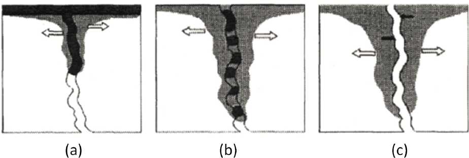
In addition to degradation reactions, contaminant mass loss to the matrix can reduce rapidly the mass of NAPLs in fractures following the cessation of migration (Parker et al., 1994, 1997; Ross and Lu, 1999; Slough et al., 1999; Reynolds and Kueper, 2002). Three snapshots during the lifespan of DNAPL in a single fracture are shown in Figure 3.7. During stage 1, continuous migration occurs while there is an active source of NAPL to feed the fracture (see Figure 3.7a). Once the source is removed, the NAPL becomes residual (stage 2) and dissolution and diffusion losses result in reduction in NAPL mass present in the fracture (see Figure 3.7b); contaminant concentrations in the matrix are near solubility levels adjacent to the fracture. During stage 3 (see Figure 3.7c) all NAPL mass has dissolved and diffused and is found in aqueous or sorbed phases in the fracture and the matrix; contaminant concentrations may decrease as clean water flows through the fracture, resulting in concentration gradients into (back) and away (forward) from the fracture. Figure 3.7 depicts contaminant concentrations migrating downward toward a higher permeability layer. Concentrations can remain above regulatory criteria for many years following the disappearance of the DNAPL phase (see Figure 3.8).
The rate of NAPL loss in the fracture depends on the solubility and diffusivity of the chemical components and the degree of sorption of the chemical(s) within the fracture and matrix. In fact, once stage 2 is reached (see Figure 3.7b), the lifespan of the contaminant as a separate phase can be on the order of days if solubility is high, fracture aperture is small, and there is an active groundwater flow regime (contaminants in NAPL form are most likely to remain in large aperture fractures with limited or no advection and low matrix porosity).
The dissolved phase storage capacity of the matrix most often exceeds greatly the NAPL-phase storage capacity of fractures. This marked difference in storage capacity could allow for the complete disappearance of the NAPL phase from fractures into the matrix. A complete change in
state as the contaminant originally introduced in the NAPL phase gradually transitions to dissolved and sorbed forms would result. The rate of mass loss from fractures is such that the lifespan of the NAPL phase in fractures can be as short as several days (Parker et al. 1994; see Figure 3.9).
The importance of diffusive mass loss to the matrix described here is directly proportional to the type of rock under consideration. The importance increases with increasing matrix porosity, increased fracture spacing, increased time since contaminant release to the subsurface, and decreased fracture aperture. For example, consideration of diffusive loss is critical in lightly to moderately fractured sandstones, but is likely to be less critical in highly fractured granite.
FINES MIGRATION AND ENTRAPMENT: EMERGENT TRANSPORT PROCESSES
Advective flow can mobilize and transport suspended fine mineral grains. Fines migration can lead to clogging at narrow throats along fractures and alter flow conditions. Furthermore, mobilized fines can be carriers for contaminants (e.g., colloidal transport of plutonium and water-NAPL Pickering emulsion transport).
Conditions for Fines Migration and Entrapment
Fine-grained sediments within fractures can rest on fracture surfaces or on larger grains until the balance between buoyant weight, drag forces, and electrical interactions prompt their mobilization. During migration, fines may also experience inertial forces. The relative balance between these forces is captured in dimensionless ratios such as those in Table 3.2.
TABLE 3.2 Governing Forces: Dimensionless Ratios
| Name | Definition | Physical Meaning |
|---|---|---|
| Archimedes number |
|
Ratio between viscous and gravitational forces |
| Froude number |
|
Ratio between inertial and gravitational forces |
| Particle Reynolds number |
|
Ratio between inertial and viscous forces |
| Maxwell number |
|
Ratio between van der Waals attraction and gravitational forces |

The ratios in Table 3.2 are written in terms of particle size dp, fluid velocity v, dynamic viscosity μ, gravity g, the Hamacker constant AH, interparticle separation s, and both particle and fluid mass densities ρp and ρf. Fines may migrate in the rock matrix; however, the high seepage velocity in fractures compared to that in the matrix sustains preferential fines migration along fractures. Fines migration will continue as long as the grain size is significantly smaller than pore constriction thresholds (e.g., when the grain size is less than one-tenth of the pore size). Note that the migrating grain can be significantly smaller than the constriction, yet multiple fine grains form bridges at pore constrictions and stop migrating.
Pore fluid chemistry and temperature determine the surface charge and zeta potential (i.e., electrokinetic potential) of fracture surfaces and fines, and the conditions conducive to chemically induced fines migration and clogging (Khilar and Fogler, 1984; Kia et al., 1987; You et al., 2013). In particular, fines agglomeration occurs when the fluid has a high ionic concentration or a pH near the isoelectric point (i.e., no net electrical charge). In this case, small colloidal particles (particles between 1–1,000 nm in solution) group into larger flocks or against the joint surfaces. Colloidal contaminants exhibit different transport behavior than conservative solute tracers; in fact colloids may travel faster than solutes because of high velocity preferential flow paths, lack of diffusion into the matrix, size exclusion (with respect to asperities on fracture surfaces), and charge effects (Vilks et al., 1997; Becker et al., 1999; Knapp et al., 2000; McCarthy et al., 2002).
The wettability characteristics of joint surfaces (i.e., the ability of the surface to maintain contact with a fluid) may favor the release of fines. Colloidal fines held by water-wet surfaces are most likely to be released in the presence of water; conversely, fines held onto oil-wet surfaces would be released under oil saturation. Reactive fluid flow, mixed-fluid flow, and fines release-migration-entrapment may be concurrent and coupled in fracture networks, such as the release of clay fines from carbonates during acid flow for oil recovery (e.g., Sakar and Sharma, 1990; Weisbrod et al., 2002; Zhang et al., 2012).
Entrapment and clogging develops when fines become trapped at fracture throats. Grain bridging extends the opening size, O, that may clog to up to 4-6 grain diameters, d—that is O/d < 4-to-6 (Valdes and Santamarina, 2006). In the case of fine grains, flock formation extends this range even further, and the fracture constriction size may exceed 10 grain diameters and still experience clogging. Fines clogging is exacerbated by biofilm growth.
Clogging Mode and Topology
Local clogging of fractures can alter the flow field, increase the flow velocity nearby, and prompt further accumulation. The hydraulic conductivity in a fracture being clogged may eventually decrease by two or more orders of magnitude (Shin et al., 1999; Ross et al., 2001; Arnon et al., 2005). In radial flow during extraction (uniform 360 degree flow toward a single point), clogging is a self-stabilizing process and results in a clogging ring around the extraction well, but not necessarily against it (Valdes and Santamarina, 2006). On the other hand, fines in the formation are flushed away near injection wells where the flow velocity is high, as long as fracture constrictions are large enough so that granular bridges are unstable. Flushing involves positive feedback: flow localizes along flushed paths and prompts further removal of fines away from the well, leaving behind fingers without fines (see Figure 3.10).
HEAT TRANSPORT AND THERMAL PROCESSES
The fate and transport of contaminants in fractured rock alters and is affected and can be controlled by thermo-hydro-chemo-bio-mechanical processes. Previous sections explored the role of hydro-mechanical, chemical, and biological effects. This section reviews thermal effects, which have special relevance in heat-generating sources (including radioactivity and geothermal) as well as for thermal remediation strategies.
Thermal Rock Mass Properties
Thermal properties relevant to processes in fractured rock include latent heat, specific heat, thermal conductivity, and thermal diffusivity. Nominal values for fractured rock components are summarized in Table 3.3. The values in the table suggest that (1) the energy required to vaporize water is equivalent to the energy required to heat the same mass of granite, shale, or carbonate by ΔT > 3,200°C; (2) the conductivity of rock-forming minerals is much greater than the conductivity of air and even water; and (3) the conductivity of dry fractured rock is much lower than the conductivity of the minerals the rock comprises. Thus, the local resistance to heat conduction (i.e., thermal contact impedance) hinders heat conduction in fractured rock.
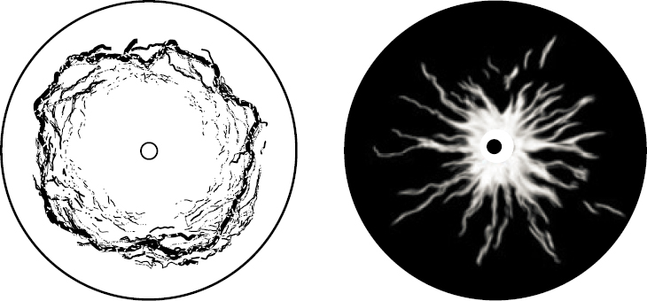
TABLE 3.3 Nominal Values of Latent Heat, Specific Heat, and Thermal Conductivity for Fractured Rock Components
| Component | Latent Heat J·g–1 | Specific Heat J·g–1·°C–1 | Conductivity W·m–1·°C–1 |
|---|---|---|---|
| Air | 1.01 | 0.02 | |
| Water | Freezing at 0°C: 334 Vaporization at 100°C: 2,260 |
water: 4.2 ice: 2.1 |
water: 0.58 ice: 2.1 |
| LNPL (benzene) | Vaporization at 80°C: 400 | 1.75 | 0.14 |
| Minerals and intact rock | quartz: 0.7 granite: 0.7 limestone: 0.8 shale: 0.6 |
quartz: 11 granite: 2–4 limestone: 1.3 shale: 1.6 |
NOTES: Thermal diffusivity is equal to the thermal conductivity divided by heat capacity. Conductivity and specific heat are temperature dependent. The specific heat, c, of dry and wet/saturated fractured rock masses can be readily computed as a mass-weighted combination of the specific heat of constituents. The thermal conductivity λ of dry and wet/saturated fractured rock depends on mass fractions, the thermal conductivity of individual constituents, and their spatial arrangement; in the absence of geometric characteristics, upper and lower bounds can be estimated using series and parallel configurations or the narrower Hashin-Shtrikman upper and lower bounds (Mayko et al., 2009).
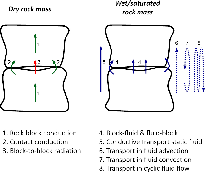
The analysis of thermal conduction paths in fractured rock masses provides valuable insight for the interpretation of thermal conductivity, its variation with rock mass structure, the effects of fluids, and state of stress (see Figure 3.11). Thermal conduction pathways include
- Heat conduction within a rock block, determined by mineral composition, in particular, the fraction of quartz.
- Heat radiation across fractures into the surrounding medium (dominant at high temperatures).
- Solid-to-solid conduction that may occur through the contacts between two rock blocks (this flow path is effective stress dependent).
- Solid-fluid and fluid-solid conduction that occurs between the fluid in fractures and the rock block. This transport path is responsible for heat storage in the matrix and release back into the fluid in fractures. The presence of water at contacts has a pronounced effect on solid-solid conduction.
- Conduction in fluid. Advective fluid flow is a major contributor to heat transport. In the absence of advective currents, convection may contribute to heat transport in fractured rocks when fracture apertures exceed the millimeter scale.
- Porosity and apertures decrease and effective stress increases with depth. Solid-to-solid conduction becomes increasingly more important in deep fractured rock masses.
Heat conduction by advective fluid flow can be estimated from the fluid flow velocity v [m/s], mass density ρ [g.m–3], heat capacity c [J.g–1.K–1], and its temperature difference with the rock mass ΔT [K]. Heat conduction through the rock matrix depends on its thermal conductivity kT [W.m–1.K–1], and the imposed thermal gradient iT [K.m–1]. If the cross-section of fractures relative to the total area is α, then the flow velocity when the heat transported by the moving fluid equals the heat flux along the rock matrix is
![]()
The required flow velocities computed for most field conditions are very small. Therefore, prevalent heat conduction by advective fluid flow (path 6 in Figure 3.11) is anticipated for most field situations.
Advective fluid flow along fractures combines with liquid-solid and solid-liquid conduction in and out of rock blocks to sustain effective heat transport during cyclic fluid flow with zero fluid mass flux at the end of the cycle (experimental evidence in Yun et al., 2011; path 8 in Figure 3.11). This process is analogous to chemical transport in cyclic fluid flow sketched in Figure 3.2. Extensive testing and analyses of this topic has been undertaken at the Yucca Mountain site including large-scale heat tests (e.g., Buscheck and Nitao, 1993) and modeling exercises (e.g., Birkholzer and Tsang, 2000).