
A variety of two-stage, or discrete, variable valve lift (DVVL) and continuously variable valve lift (CVVL) systems have recently been incorporated in production vehicles. Several systems that have been introduced with the objective of reducing fuel consumption are described in this Appendix.
DISCRETE VARIABLE VALVE LIFT (DVVL) SYSTEMS
Two-stage, or discrete, variable valve lift (DVVL) systems generally rely on the cam profile switching (CPS) concept. CPS provides a means of switching the actuation of the intake valves between a standard high lift cam for maximum power operation and a low lift cam for efficient light load operation. The low lift cam for light load operation reduces fuel consumption by transferring air flow control from the throttle to the intake valves which results in reduced pumping losses. The incorporation of the CPS concept in numerous production applications is described in the following sections.
Honda i-VTEC
The Honda i-VTEC (intelligent-Variable Valve Timing and Lift Electronic Control) system provides continuous cam phasing (VVT) and discrete variable valve lift (DVVL) control using the cam profile switching (CPS) concept. The VTEC system consists of a camshaft with a center high lift cam and outer low lift cams and associated rocker arms, as shown in Figure I.1. For light load operation, the valves are operated by the two outer, low lift cams and associated outer rocker arms. For higher power operation, hydraulic pressure is used to insert a pin to lock the middle rocker arm to the outer rocker arms for operation on the high lift cam. Cam phasing is accomplished with a hydraulic cam phaser.
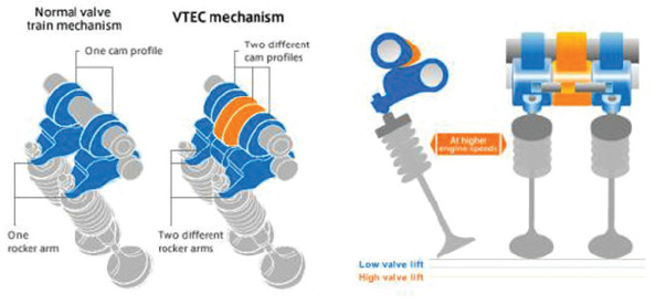
FIGURE I.1 Honda i-VTEC.
SOURCE: Courtesy of Honda (2013).
Audi Valvelift System (AVS)
The Audi Valvelift System (AVS) uses the cam profile switching concept (CPS) with a high lift cam lobe (11 mm)
and low lift cam lobes. Two different low lift cam lobes (5.7 mm and 2 mm) are used to create swirl for improved mixing at low speeds. The two sets of the low and high lift cams for each of the two intake valves of a cylinder are mounted on a single carrier piece so that the active cams depend on the longitudinal position of the carrier piece on the camshaft. Each cam carrier piece has two spiral grooves. A pin engages one of the spiral grooves to move the carrier axially from the low lift cam to the high lift cam position. Another reverse spiral groove and pin are used to return the carrier to the low lift cam position. The pins are electrically actuated. The Audi AVS system was first introduced in the 2006 1.8L TFSI engine in the Audi A3 and subsequently applied to the 2.8L and 3.2L V6 FSI engines. Audi has indicated that the AVS system provides up to a 7 percent reduction in fuel consumption.
Mercedes Camtronic
The Mercedes Camtronic system is similar to the Audi AVS system except that it uses fewer cam carrier pieces. In the Mercedes system, each cam carrier piece serves two adjacent cylinders, instead of only one cylinder as in the Audi AVS system. Mercedes introduced the Camtronic system on the new M270 series four-cylinder engine in 2012.
Chevrolet Intake Valve Lift Control
The Chevrolet intake valve lift control (IVLC) system also uses the cam profile switching concept with low and high lift cams. The system uses rocker arms consisting of two roller followers that are electro-hydraulically latched to the rocker arm for operation on either the low or high lift cams. Chevrolet introduced the IVLC system on their 2.5L EcoTec four-cylinder engine in the 2014 MY Chevrolet Impala (SAE 2012). General Motors indicates that the IVLC system will provide a fuel savings of up to 1 mpg (approximately 4 percent (Kelly Blue Book 2013).
CONTINUOUSLY VARIABLE VALVE LIFT (CVVL) SYSTEMS
Several different principles have been applied to develop continuously variable valve lift systems (CVVL) that range from mechanical systems to hydraulic systems. Several systems that have been introduced in production with the objective of reducing fuel consumption are described here.
BMW Valvetronic
The BMW Valvetronic system was the first continuously variable valve lift mechanism, which went into production in the BMW 316ti in 2001. The goal of Valvetronic was to reduce fuel consumption. Since air flow, and thus engine output, is controlled by valve lift with the Valvetronic system, the conventional throttle valve is disabled which reduces pumping losses. Overall, BMW claims that Valvetronic can provide a 10 percent reduction in fuel consumption (Autozine 2013). Valvetronic adds an intermediate rocker arm between the camshaft and the roller finger follower that actuates the valve. The pivot location of the intermediate rocker arm is varied with an eccentric shaft controlled by an electric motor through a worm gear set. Rotating the eccentric shaft to extend the pivot location of the intermediate rocker arm results in an increase in valve lift. Although Valvetronic reduces fuel consumption at part load, maximum power is not increased since the additional components result in additional friction and inertia. The Valvetronic system adds significant height above the cylinder head so that packaging the engine is more difficult.
Toyota Valvematic (Continuous VVL)
The Toyota Valvematic system, shown in Figure I.2, inserts an intermediate rocker shaft between the camshaft and the roller rocker arm that actuates the valve (U.S. Patent Application Publication 2014). The intermediate rocker shaft contains roller followers offset from the center of the intermediate rocker shaft and additional followers. The angle between the roller follower and additional follower is controlled by an electric motor. Increasing this angle increases the resultant valve lift. Toyota implemented the Valvematic system on their 1.6L, 1.8L and 2.0L engines and subsequently introduced the system on the 2014 MY 1.8L Corolla in the U.S. market. The Valvematic system was reported to improve fuel economy by 5 percent and increase power by 6 percent in the 2014 MY Corolla (Borge 2013).
Multiair Electro-Hydraulic Valve-Timing System
In the Fiat Chrysler Multiair system, shown in Figure I.3, a piston, operated by a mechanical intake cam, is connected to the intake valve through a hydraulic chamber. The hydraulic chamber includes a solenoid valve. When the solenoid valve is closed, the oil in the line acts as a solid body and transmits the intake cam motion directly to the intake valve. By opening the solenoid valve, the hydraulic pressure is relieved and the intake valve closes under the action of the valve spring. A dedicated hydraulic brake is used to provide a soft landing of the intake valve for all engine operating conditions. A wide range of intake valve actuation modes can be obtained by controlling the solenoid valve, as illustrated in Figure I.3.
- For maximum power at high speed, the solenoid valve is always closed so that full valve opening is obtained by following the intake cam.
- For low speed torque, the solenoid valve is opened near the end of the cam profile to provide early intake valve closing to eliminate backflow into the intake manifold to maximize the air mass trapped in the cylinders.
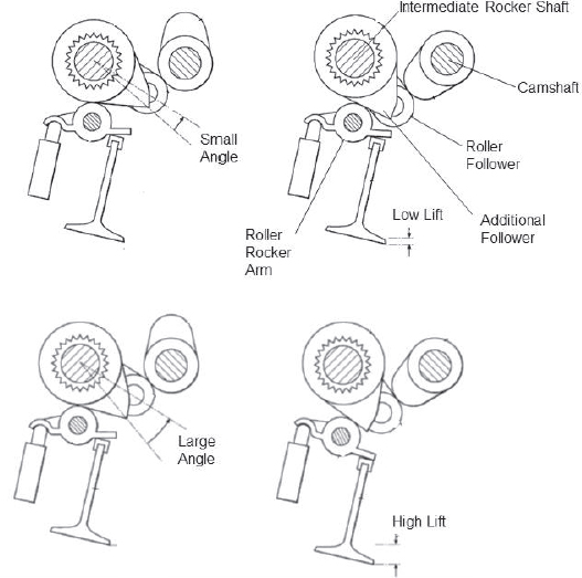
FIGURE I.2 Toyota Valvematic variable valve lift systems illustrating low and high lift configurations resulting from adjusting the angle between the intermediate roller follower and additional follower to obtain the desired valve lift.
SOURCE: Boutell (2014). Courtesy of Toyota Motor Engineering & Manufacturing North America, Inc.
- At part load conditions, the solenoid valve can be opened earlier resulting in shortened valve open times to control trapped air mass as a function of the required torque without throttling (partial valve opening).
- At idle, the solenoid valve can be closed after the mechanical cam has started and then opened early, resulting in partial valve opening so that air flows faster past the intake valve to enhance in-cylinder turbulence (late valve opening).
- The last two actuation modes can be combined to open the intake valve twice during each intake stroke to enhance turbulence and combustion rates at light loads.
Fiat Chrysler indicated that Multiair can provide a 10 percent reduction in fuel consumption with the elimination of pumping losses. Additionally, Multiair can provide up to a 10 percent increase in power when a power-oriented mechanical cam profile is used. Low speed torque can be improved by up to 15 percent (Murphy 2010). Multiair was first introduced in the 2010 MY 1.4L Chrysler Fiat 500. The next application was in the 2013 MY 2.4L Dodge Dart. Subsequent applications have included the 2014 MY Jeep Cherokee, and the 2015 MY Chrysler 200, Jeep Renegade, and Ram ProMaster City.
REFERENCES
Borge, J.L. 2013. Toyota engineers put a shine into the 2014 Corolla. SAE International, Automotive Engineering Magazine, September 9. http://articles.sae.org/12444/.
Boutell, B.T. 2014. Variable valve Operation Control Method and Apparatus. U.S. Patent Application Publication No. US 2014/0102385 A1, April 17.
Cam-changing + Cam-phasing VVT. Autozine Technical School. Accessed June 23, 2013. http://www.autozine.org/technical_school/engine/vvt_31.htm.
Continuous Variable Valve Lift (CVVL). Autozine Technical School. Accessed September 6, 2013. http://www.autozine.org/technical_school/engine/vvt_5.html.
Honda. 2013. The VTEC breakthrough: solving a century-old dilemma. http://world.honda.com/automobile-technology/VTEC/.
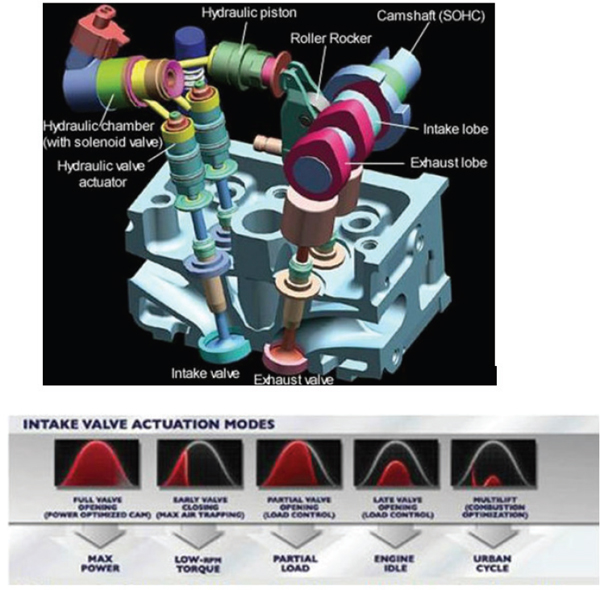
FIGURE I.3 Multiair electro-hydraulic valve-timing system.
SOURCE: Murphy (2010). Credited to FCA US LLC.
Kelly Blue Book. 2012. 2014 Chevy Impala Gets Variable Valve Lift on Ecotec 4-cylinder. Kelly Blue Book, September 17. Accessed August 6, 2013. http://www.kbb.com/car-news/all-the-latest/2014-chevy-impalagets-variable-valve-lift-on-ecotec-4_cylinder/2000008572/.
Murphy, T. 2010. Fiat Breathing Easy With MultiAir. WardAuto, March 26. http://wardsauto.com/ar/fiat_breathing_multiair_100326.
SAE. 2012. GM’s new modular Ecotec I4 architecture adds first variable intake-valve lift. October 9. http://articles.sae.org/11466/.


