
Technologies for Reducing Fuel Consumption in Spark-Ignition Engines
The spark-ignition (SI) engine, fueled with gasoline, has long been the dominant engine for the light-duty fleet in the United States. This dominance is expected to continue through the 2025 time frame and beyond. EPA and NHTSA, in their analysis for the MY 2017-2025 standards, have projected potential compliance paths for each company and for the industry fleet as a whole using the Environmental Protection Agency’s (EPA) OMEGA model and the National Highway Traffic Safety Administration’s (NHTSA) Corporate Average Fuel Economy (CAFE) model, also known as the Volpe model (EPA/NHTSA 2012a).1 The EPA/NHTSA projected compliance demonstration path for the industry fleet as a whole, shown in Table 2.1, indicates that SI engines are projected to be used in 98 percent of the 2025 MY fleet, with 2 percent projected to be battery electric vehicles. Of the 98 percent of gasoline engines, 15 percent are projected to be in stop-start (SS), 26 percent are projected to be used in mild hybrid electric drivetrains (MHEVs), and 5 percent will be used in hybrid electric drivetrains (HEVs). With this continuing dominance projected for spark-ignition gasoline engines, technologies for reducing the fuel consumption of these engines will be essential for achieving the future CAFE standards.
This chapter considers technologies and associated costs for reducing fuel consumption in SI gasoline engines. The fundamentals of SI engine efficiency will be reviewed first to provide a context for examining the potential of individual technologies. With this background, the individual technologies for reducing fuel consumption will be reviewed within the following categories:
- Technologies EPA/NHTSA included in the final CAFE rule analysis;
- Technologies EPA/NHTSA considered for but did not include in the final CAFE rule analysis;
- Technologies EPA/NHTSA neither considered for nor included in the final CAFE rule analysis;
- Control systems, models and simulation techniques; and
- Emission control systems for meeting future criteria pollutant emission standards.
Estimates of the potential effectiveness of each of the technologies are presented and expressed in terms of percent reduction in fuel consumption. The fundamental means by which each technology achieves the reduction in fuel consumption—such as through reductions in friction, reductions in pumping loss, or improvements in thermodynamic efficiency—are identified. Potential interactions with other technologies, whereby the effectiveness of an individual technology might be enhanced but more likely would be diminished, are discussed. For each technology that EPA/NHTSA considered applicable in complying with the final CAFE rule, EPA/NHTSA provided estimates of the technology’s effectiveness and cost. These estimates are reviewed in this chapter, and, where appropriate, modifications to the effectiveness and/or cost are suggested.
SI ENGINE EFFICIENCY FUNDAMENTALS
SI engines are often referred to as Otto cycle engines to describe the idealized thermodynamic processes of the engine. The idealized thermodynamic cycle for the Otto cycle engine is shown on a pressure versus volume (P-V) diagram in Appendix D, together with other thermodynamic cycles for several other engines discussed later. An energy balance for an SI gasoline engine operating at a condition representative of the Federal Test Procedure (FTP)2 cycle,
_____________
1 Although the final rule illustrates possible compliance paths, each company is expected to plot its own future course to compliance.
2 The FTP represents the city driving portion of the test cycles used to estimate fuel economy and compliance with the CAFE/GHG standards. Chapter 10 discusses these test cycles and issues associated with them.
| Mass Reductionb | Turbocharged / Downsized 18-27 BMEPc | 8-speed Automatic Transmission | 8-speed Dual Clutch Transmission | Mild Hybrid | Strong Hybrid | Electric Vehicle | Diesel | ||||||||||||
| Fleet | –7 | 93 | 35 | 56 | 26 | 5 | 2 | 0 | |||||||||||
aTechnology penetrations for Aston Martin, Lotus and Tesla are not included here but can be found in EPA’s Regulatory Impact Analysis (RIA).
bNegative values for mass reduction represent percentage of mass removed.
cBMEP, brake mean effective pressure.
SOURCE: EPA/NHTSA (2012a, Table III-29).
shown in Figure 2.1, is useful for identifying potential fuel consumption reduction opportunities. Technologies that improve thermodynamic efficiency or reduce losses and result in an increase in brake work as a percentage of the total fuel energy are effective in reducing fuel consumption. Factors affecting the various components of the energy balance are discussed in this section, while definitions and efficiency fundamentals are discussed in Appendix E.
The energy balance in Figure 2.1 illustrates current typical efficiencies and opportunities for reducing fuel consumption in SI gasoline engines. Energy input into a vehicle in the form of fuel produces energy output in the form of heat and work. Energy output goes into three areas: exhaust enthalpy, heat to coolants, and indicated work, where the indicated work is work done on the piston and exhaust enthalpy and heat to coolants are thermodynamic efficiency losses. A portion of the indicated work on the piston is further categorized as accessory work (required for the engine-driven pumps, cooling fan and alternator), rubbing friction work, and pumping work to move air into and exhaust out of the cylinders. The remaining portion of indicated work is the work that goes into the driveline (through the transmission, final drive, axles and tires) to propel the vehicle. That portion of the indicated work is termed brake work.3 The energy output from the input fuel energy is described further below:
- Approximately one-third of the fuel energy is lost as exhaust enthalpy and another one-third is lost as heat rejected to coolant. Friction losses are generally manifested as additional heat transferred to coolant or oil.
- Brake work is nearly 40 percent lower than indicated work on the FTP cycle due to pumping losses, rubbing friction losses and accessory drive requirements.
- Improvements in thermodynamic efficiency increase the fraction of fuel energy that goes into indicated work.
- Pumping losses comprise approximately 5 percent of the total fuel energy. If pumping losses could be reduced by 20 percent, or 1 percent of the fuel energy, fuel consumption could be reduced by 2.8 percent (applying an indicated thermal efficiency (ITE) of 36 percent).4
- By increasing indicated work (work done on the piston) through improvements to thermodynamic efficiency by 1 percentage point, from 36 percent to 37 percent, fuel consumption could be reduced by 2.7 percent.5
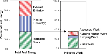
FIGURE 2.1 Energy balance for SI gasoline engine for an operating condition representative of the FTP cycle.
SOURCE: derived from data in Heywood (1988).
_____________
3 Engine torque is measured with the engine connected to a dynamometer. The power delivered by the engine, which is absorbed by the dynamometer, is the product of torque and speed (Ameri 2010). The value of engine power measured in this manner is called brake power. This power is the usable power delivered by the engine to the load, in this case a brake (Heywood 1988).
4 Indicated Thermal Efficiency (ITE) = Indicated work (energy)/fuel consumption (energy).
Reducing work by an amount equal to 1 percent of fuel energy would reduce fuel consumption by 2.8 percent, which is the fuel required to produce this work as governed by the cycle efficiency, so that fuel consumption (FC) = Indicated Work/ITE = 1.0/.36 = 2.8 percent.
5 The baseline case assumes 36 percent ITE, as shown in Figure 2.1. The indicated work is calculated as follows:
100 percent fuel energy × 36% ITE/100 = 36 percent indicated work. The amount of fuel energy required to produce the same indicated work of 36 percent (on the original fuel energy basis) is then calculated as follows:
fuel energy × 37% ITE/100 = 36 percent indicated work, or
fuel energy = 36/37 × 100 = 97.3 percent fuel energy.
With 37 percent ITE (a 1 percentage point increase), the fuel energy required is reduced by 2.7 percent relative to the baseline case.
- Rubbing friction losses are approximately 8 percent of the total fuel energy. If rubbing friction losses could be reduced by 25 percent, or 2 percent of the fuel energy, fuel consumption could be reduced by 5.6 percent (applying 36 percent ITE).
- Engine accessories (oil pump, water pump, fan and alternator) require work that consumes approximately 1 percent of the fuel energy. If engine accessory power requirements could be reduced by 50 percent, or 0.5 percent of the fuel energy, fuel consumption could be reduced by 1.4 percent (applying 36 percent ITE).
- Although a typical SI engine may have 22 percent brake thermal efficiency at representative FTP operating conditions (where brake work is shown as a percent of fuel energy input), brake thermal efficiencies significantly greater than 30 percent are typical at optimum operating conditions.
Approaches to increasing the brake work output are summarized below, following which specific technologies to implement these approaches are discussed in the remainder of this chapter.
Thermodynamic Factors
Thermodynamic factors affect indicated thermal efficiency. Thermodynamic factors include combustion timing and duration, compression and expansion ratios, working fluid properties, and heat transfer. Improvements in ITE can be achieved by modifying these thermodynamic factors as follows:
- Reduced combustion duration with optimum timing. Reducing the combustion duration while maintaining optimum timing releases more of the fuel energy closer to the optimum piston location (top dead center), thereby allowing a longer expansion to yield an increase in cycle work. Fast burn combustion systems that meet manufacturers’ combustion pressure rise rates for acceptable noise, vibration and harshness (NVH) have been developed over the past several decades and are generally incorporated in current vehicles (NRC 2011). The final CAFE rule does not specifically propose technologies that would further reduce combustion duration, probably because of concerns about NVH.
- Increased compression ratios. Increases in the mechanical compression ratio can provide an increase in cycle efficiency. Variable valve timing can also be used to modify the effective expansion ratio and compression ratio. Late exhaust valve opening increases the effective expansion ratio to increase cycle work. Early or late intake valve closing decreases the effective compression ratio, thereby reducing the compression work while maintaining the same expansion ratio, resulting in a further increase in cycle efficiency for a given compression ratio.
- High specific heat ratio of the working fluid. For an idealized Otto cycle, the thermodynamic efficiency increases with increased specific heat ratio (Heywood 1988).6 Air is preferred over exhaust gas as a diluent due to the higher specific heat ratio of air, but exhaust emission requirements using three-way catalysts (TWC) currently preclude the use of air as a diluent. Exhaust gas recirculation (EGR) is an option instead of air. However, some manufacturers are considering lean burn combustion systems using air as a diluent, if fuel changes are sufficient to reduce sulfur content in gasoline to facilitate the application of suitable emission control systems.
- Reduced heat transfer from the working fluid. Approximately one-third of the fuel energy is lost to the combustion chamber walls, which lowers the average combustion gas temperature and pressure, in turn reducing the work transferred to the piston. This heat transfer is generally required to protect engine materials, limit oil degradation, and preclude the onset of combustion knock.7 Although reduced cooling might be considered in engine locations beyond the combustion chamber, such as around the exhaust ports, thermodynamic efficiency will not be improved with such reductions. Split cooling systems are used by some manufacturers to independently optimize the cooling of the cylinder head and the block to achieve friction reductions and faster warm-up during cold starting.
- More efficient operating conditions. As noted earlier, the 22 percent brake thermal efficiency shown in Figure 2.1 at representative FTP operating conditions is significantly lower than the >30 percent brake thermal efficiency typically achieved at an optimum operating condition. The significant technologies that directly address this potential improvement include
_____________
6 The efficiency of the ideal Otto cycle is defined as follows:
η = 1 – 1/CRγ-1 where:
η = efficiency
CR = compression ratio
γ = cp/cv = ratio of specific heats
(= specific heat at constant pressure/specific heat at constant volume)
This equation indicates that larger values of γ result in higher values of efficiencies.
7 Knock is an abnormal combustion phenomenon characterized by noise resulting from the autoignition of a portion of the fuel-air mixture ahead of the advancing flame. As the flame propagates across the combustion chamber, the unburned mixture ahead of the flame, called the end gas, is compressed, causing its pressure, temperatures and density to increase. The end gas may autoignite, thereby spontaneously and rapidly releasing a large part of the chemical energy. This causes high-frequency pressure oscillations inside the cylinder that produce the sharp metallic noise called knock. The knock phenomena are governed by engine variables and the anti-knock quality of the fuel, defined by the fuel’s octane number (Heywood 1988, pp. 375 and 470).
turbocharging and downsizing, cylinder deactivation, and hybridization. Also addressing this opportunity are transmissions with a higher number of ratios.
Pumping Work
Reductions in pumping work can be achieved with systems such as variable valve timing and variable valve lift, turbocharged and downsized engines, and cylinder deactivation. Transmissions with a higher number of gears also provide the opportunity to reduce pumping work of the engine.
Friction Work
Approaches for reducing engine friction include low-friction lubricants, reduction of engine friction through design modifications, turbocharged and downsized engines, cylinder deactivation, and hybridization. Transmissions with a higher number of gears also provide the opportunity to reduce engine speed to reduce friction work.
Accessory Work
Electrically-driven water and oil pumps controlled to meet demands, rather than belt-driven pumps that operate at a fixed ratio of engine speed, also will reduce fuel consumption.
FUEL CONSUMPTION REDUCTION TECHNOLOGIES – IDENTIFIED IN FINAL CAFE RULE ANALYSIS
Specific technologies to implement the approaches previously identified for reducing fuel consumption are discussed in this section in the order presented in the final CAFE rule. Table 2.2 lists some of the fuel consumption reduction technologies directly applicable to SI gasoline engines from the Final Regulatory Impact Analysis (FRIA) (EPA 2012; NHTSA 2012). The table shows the specific categories of improvements in thermal efficiency or reduction in losses that are impacted by each technology. The fuel consumption reductions for each technology listed in the table are estimates by NHTSA (2012), and the distributions of the reductions in losses and improvements in ITE for each technology are from the EPA Lumped Parameter Model.
In the first part of this section, overviews of each technology are provided and the fuel consumption reduction principles are described. The committee’s estimates of fuel consumption reductions and 2025 costs (2010 dollars) are presented and compared to NHTSA’s estimates. The second part of this section discusses costs estimated by the committee that differed from those of NHTSA. Fuel consumption reduction effectiveness and costs are generally presented for a midsize car with an I4 engine for simplicity. However, a complete set of estimates for a midsize car with an I4 dual overhead cam (DOHC) engine, a large car with a V6 DOHC engine, and a large light truck with a V8 overhead valve (OHV) engine are provided in Table 2A.1 for effectiveness and Tables 2A.2a, b, and c for 2017, 2020, and 2025 direct manufacturing costs, respectively (Annex tables at end of chapter).
Rubbing Friction Reduction
Engine friction losses comprise approximately 8 percent of the fuel energy, as shown in Figure 2.1 and Table 2.2. As discussed earlier, if friction could be reduced by 25 percent, a 5.6 percent reduction in fuel consumption could be achieved. This section will describe technologies that can be applied to reduce engine friction.
Low Friction Lubricants - Level 1 (LUB1)
Lower viscosity engine lubricants are capable of reducing engine rubbing friction. The final CAFE/GHG TSD proposes that shifting to lower viscosity lubricants—in particular, changing from a 5W-30 motor oil to 5W-20 or 0W-20—would reduce friction through reductions in high and/or low and high temperature viscosities (EPA/NHTSA 2012b). The TSD recognizes that testing would be needed in order to ensure that durability is maintained. Since some manufacturers currently specify 5W-20 motor oil, the fuel consumption benefit is already incorporated in some current vehicles. However, 5W-30 may need to be retained for turbocharged engines. Low friction lubricants were projected in the TSD to provide a 0.5 to 0.8 percent reduction in fuel consumption at a cost of $4.02, which is consistent with the estimates provided in the Phase 1 study (NRC 2011).
Reducing the viscosity of motor oils to improve fuel economy can be accomplished with (1) better base stocks and/or (2) more friction modifiers in the additive package. The quality and service classifications of motor oil, as well as an indication of their fuel economy improvement potential, are provided or certified by the following organizations (Carley 2007):
- SAE provides a numerical code system for grading motor oils according to their viscosity characteristics. Taking 10W-30 motor oil as an example, the first number (10W) refers to the viscosity grade at low temperatures (W for winter) and the second number (30) refers to the viscosity grade at high temperatures. The relationship of SAE numerical codes and kinematic viscosity, which directly affect fuel economy, is shown for several examples in Table 2.3.
- The International Lubricant Standardization and Approval Committee (ILSAC) consolidates and coordinates standards for motor oil testing. ILSAC developed minimum performance standards for gasoline-powered passenger car and light truck oils, which became known as gasoline-fueled (GF) motor oil standards.
| Midsize Car Technologiesa,b | Overall % Reduction in FCc | Indicated Efficiency %d | Indicated Work as a % of Baseline Fuel | Friction Loss as a % of Baseline Fuel | Pumping Loss as a % of Baseline Fuel | Accessory Loss as a % of Baseline Fuel | Brake Work as a % of Baseline Fuele | ||||||||||||
| Baseline Engine - Initial Values | 36.00 | 36.00 | 8.00 | 5.00 | 1.00 | 22.0 | |||||||||||||
| Low Friction Lubricants - Level 1 | 0.70 | 36.00 | 35.75 | 7.75 | 5.00 | 1.00 | 22.0 | ||||||||||||
| Incremental Changes: | (0.25) | ||||||||||||||||||
| Engine Friction Reduction - Level 1 | 2.60 | 36.00 | 34.82 | 6.81 | 5.00 | 1.00 | 22.0 | ||||||||||||
| Incremental Changes: | (0.94) | ||||||||||||||||||
| Low Friction Lubricants and Engine Friction Reduction - Level 2 | 1.26 | 36.00 | 34.38 | 6.36 | 5.00 | 1.00 | 22.0 | ||||||||||||
| Incremental Changes: | (0.45) | ||||||||||||||||||
| Variable Valve Timing - Dual Cam Phasing - DOHC | 5.10 | 36.10 | 32.63 | 6.17 | 3.53 | 1.00 | 22.0 | ||||||||||||
| Incremental Changes: | (0.09) | (0.19) | (1.47) | ||||||||||||||||
| 32.71 | |||||||||||||||||||
| Continuously Variable Valve Life | 4.6 | 36.10 | 31.21 | 5.97 | 2.22 | 1.00 | 22.0 | ||||||||||||
| Incremental Changes: | (0.20) | (1.31) | |||||||||||||||||
| Cylinder Deactivation | 0.7 | 36.10 | 30.99 | 5.94 | 2.03 | 1.00 | 22.0 | ||||||||||||
| Incremental Changes: | (0.03) | (0.19) | |||||||||||||||||
| SGDI | 1.50 | 36.65 | 30.53 | 5.94 | 2.03 | 1.00 | 22.0 | ||||||||||||
| Incremental Changes: | 0.46 | ||||||||||||||||||
| 30.99 | |||||||||||||||||||
| 18 bar BMEP Turbocharging and Downsizing | 8.30 | 37.48 | 28.42 | 5.04 | 1.00 | 1.00 | 22.0 | ||||||||||||
| Incremental Changes: | 0.64 | (0.90) | (1.03) | ||||||||||||||||
| 29.06 | |||||||||||||||||||
| Cumulative (Multiplicative) Reduction in Fuel Consumption | -22.50 | -3.0 | -4.0 | ||||||||||||||||
| Remaining | 5.0 | 1.0 | |||||||||||||||||
| Percent Reductions in Losses/Improvements in Indicated Efficiency | 4.1 | -37.0 | -80.0 | ||||||||||||||||
a Reductions in fuel consumption (FC) for specific technologies are from NHTSA RIA, Table V-126 (2012).
b Distributions of reductions in losses for each technology are from EPA Lumped Parameter Model.
c Fuel consumption reductions for technologies listed are multiplicatively combined to provide overall reductions using the factor (100-%FC)/100.
d Indicated Thermal Efficiency = Indicated Work/Fuel Consumed (where fuel consumed is reduced by % reduction in fuel consumption for each technology).
e Brake Work = Indicated Work - Friction Loss - Pumping Loss - Accessory Loss.
-
These standards cover all aspects of oil performance in engines together with emission system durability and fuel economy. In 1997, ILSAC introduced an “Energy Conserving-EC” rating for motor oils that demonstrated improved fuel economy. Since that time, a number of GF oil ratings have been introduced, each one providing a target level improvement in fuel economy. However, ILSAC test procedures do not correspond to the EPA fuel economy test procedure. The latest rating, GF-5, introduced in late 2010, was expected to improve fuel economy by 0.5 percent over the previous GF-4 rated motor oil (Lubrizol 2010), which is in the range expected with the first level of low friction lubricants.
- The American Petroleum Institute (API) provides motor oil specifications. The latest API specification for gasoline engines is “SN” which matches the ILSAC GF-5 rating.
TABLE 2.3 Viscosity Grades of Engine Motor Oils
| Automotive Lubricant Viscosity Grades (Engine Oils – SAE J 300, Dec. 1999) | |||||||||||||||||||
| SAE | Low Temperature Viscosities | High-Temperature Viscosities | |||||||||||||||||
| ViscosityGrade | Cranking max at temp °C (mPa.s) | Pumping max at temp °C (mPa.s) | Kinematic at 100°C (mm2/s) | High Shear Rate at 150°C, 10/s (mPa.s) | |||||||||||||||
| min | max | min | |||||||||||||||||
| 0W | 6200 at –35 | 60 000 at –40 | 3.8 | — | — | ||||||||||||||
| 5W | 6600 at –30 | 60 000 at –35 | 3.8 | — | — | ||||||||||||||
| 10W | 7000 at –25 | 60 000 at –30 | 4.1 | — | — | ||||||||||||||
| 20 | — | — | 5.6 | <9.3 | 2.6 | ||||||||||||||
| 30 | — | — | 9.3 | <12.5 | 2.9 | ||||||||||||||
SOURCE: www.tribology-abc.com.
Lubricants are also important enablers of some technologies. A GF-6 oil rating is under development, with a target release in late 2016, to introduce a new, lower viscosity grade oil (Miller et al. 2012). The GF-6 rating will address several needs specific to turbocharged, downsized engines. The rating will ensure increased fuel economy throughout the oil drain interval. Perhaps more important, it will protect against engine-oil-caused, low-speed pre-ignition (LSPI), which has become a concern for turbocharged, downsized engines, as discussed later in this chapter. The GF-6 rating will also provide adequate wear protection for stop-start engines, which experience frequent starts and stops after extended periods of downtime.
As described in Appendix F, by changing from 5W-30 to 5W-20 oil, the committee estimated that low-friction lubricants – level 1 could provide approximately a 0.5 percent reduction in fuel consumption, which is within the range estimated by EPA/NHTSA in the final CAFE rule. EPA/NHTSA estimated that the incremental direct manufacturing cost of $3 for changing lubricants is due to the incremental cost of the oil. The overall cost, however, may be offset because fewer oil changes will be required. The amortized durability testing costs by the vehicle manufacturers would be reflected in the indirect cost.
The wide range of engine motor oils specified for 2013 MY vehicles certified by EPA are listed in Table 2.4. Not all of the vehicles certified by EPA specified 5W-20 or lower viscosity motor oil, suggesting that some vehicles may have the opportunity of using the lower friction lubricants after completing adequate testing. However, other vehicles may be limited in changing to lower viscosity oils due to operating loads and temperature concerns.
TABLE 2.4 Engine Motor Oils Specified for 2013 MY Light-Duty Vehicles (LDVs)
| 10W Low-Temperature Viscosity Oils | 5W Low-Temperature Viscosity Oils | 0W Low-Temperature Viscosity Oils |
| 10W-60 (Aston Martin) | 5W-40 | 0W-40 |
| 10W-40 | 5W-30 GF4 | 0W-30 |
| 5W-20 GF4 | 0W-20 (Toyota) | |
| 5W-20 GF5 | 0W-20 GF4 (Mazda, Kia) | |
| 0W-20 GF5 (Honda) | ||
SOURCE: EPA Fuel Economy Data MY 2013.
Low-Friction Lubricants - Level 2 (LUB2)
Several years ago, a 0W-20 synthetic motor oil with lower viscosity during cold-start and warm-up operation was introduced in some high-end cars. Recently, Japanese automakers approved the use of 0W-20 motor oils in some of their mainstream vehicles. The 0W-20 motor oil improves fuel economy during cold-start and warm-up operation and has been reported to improve fuel economy by 0.5 to 1.0 percent on the EPA test procedure.
In 2013, SAE released a new standard for SAE viscosity grade 16 that is likely to appear as 5W-16 and 0W-16 oils. SAE is currently working on a specification for 0W-12 motor oils. These lower viscosity oils at operating temperatures are intended to improve the fuel economy of engines specifically designed for these oils. Use of these oils in other engines could result in premature wear. One automaker is reported to be specifying 0W-16 oil in several vehicles, but these vehicles have not yet been certified by EPA in the United States, and the extent of the engine design modifications to ensure adequate durability is unknown (Swedberg 2013).
The combined effects of low-temperature viscosity reduction and 100°C viscosity reduction are estimated in Appendix F to provide an overall 1.0 percent reduction in fuel consumption for low friction lubricants - level 2, which is similar to the level of effectiveness estimated by EPA/NHTSA in the TSD.
Synthetic 0W-20 motor oil costs $7.17 to $8.79 per quart compared to $3.99 to $6.29 per quart for nonsynthetic 5W-20 motor oil. Therefore, oil changes for a car requiring 0W-20 motor oil would cost $4.40 to $24.00 more than a car using conventional oil. Since oil change intervals may be nearly twice as long compared to cars using conventional
motor oils, an owner would expect to have the same or even lower annual maintenance costs. However, the higher cost of the initial oil fill for the 0W-20 motor oil is assumed to be included under Low Friction Lubricants (LUB2). Engine design changes are expected to be required to provide compatibility with these low-viscosity oils. These changes may include changes in oil pressure, bearing materials, and clearances, and other changes in specifications for wear surfaces in the engine.
Engine Friction Reduction - Level 1 and Level 2 (EFR1 and LUB2_EFR2)
Engine design changes are capable of reducing engine rubbing friction. The design of engine components, including low-tension piston rings, piston skirt design, roller cam followers, crankshaft design and bearings, material coatings, material substitution, optimal thermal management, and piston and cylinder surface treatments are projected in the final TSD to provide reductions in fuel consumption (EPA/NHTSA 2012a). For engine friction reduction through design of engine components (EFR1), NHTSA projected a 2.0 to 2.7 percent reduction in fuel consumption.
In addition to the first level of engine friction reduction, the final CAFE TSD added a second level of incremental reductions in engine friction, which may be required when a second level of low-friction lubricants is applied. For this second level of reductions in engine friction and low-friction lubricants, referred to as LUB2_EFR2, NHTSA projected an incremental 1.04 to 1.37 percent reduction in fuel consumption.
Examples of the main engine components on which vehicle manufacturers and suppliers are working to reduce friction are smaller, low-friction bearings; pistons with smaller skirts with coatings and low tension piston rings; diamond-like coatings on valve lifters; low-friction crankshaft seals; and the elimination of balance shafts (Truett 2013). Further discussion of these opportunities is provided in Appendix F.
By applying the design changes described in Appendix F, consisting of 50 percent reduction in bearing losses, 50 percent reduction in piston ring pressure, 10 percent reduction in valvetrain losses, and 50 percent reduction in seal losses, to the baseline overall engine friction, a 10 percent reduction in overall friction would be expected (Ricardo Inc. 2012). A 10 percent reduction in friction could reduce fuel consumption by 2.2 percent, based on the relationship developed earlier in this chapter and in Appendix G. An engine with balance shafts having roller bearings instead of journal bearings could realize an additional 0.4 percent reduction in fuel consumption.
The application of these technologies to reduce engine mechanical friction is illustrated in Figure 2.2 for a Nissan 1.2L three-cylinder gasoline engine (Kobayashi et al. 2012). This engine has the first known application of diamond-like carbon (DLC) coated piston rings for reduced friction. A variable displacement oil pump is used to supply the additional oil pressure for this high-output engine without increasing the oil pump work at moderate loads. Mirror-finished bearing surfaces and bore circularity are applied to further reduce engine friction.
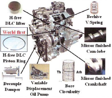
FIGURE 2.2 Low-friction technologies in a Nissan 1.2L three-cylinder gasoline engine.
SOURCE: Kobayashi (2012). Reprinted with permission from SAE paper 2012-01-0415. Copyright © 2012 SAE International.
To provide the same performance with a smaller displacement engine, higher brake mean effective pressure (BMEP)8 is required and can be achieved through turbocharging and downsizing. A high BMEP engine is likely to have higher friction than a naturally aspirated engine with the same displacement, even after applying the modifications described above to reduce engine friction (Truett 2013). This is because the higher cylinder pressures and temperatures exert greater loads on the rubbing surfaces. The directional impact of friction reduction on fuel consumption after engine downsizing is discussed in Appendix G. The friction reduction required in a 50 percent downsized engine would be approximately double that required in the baseline, naturally aspirated engine to achieve the same reduction in fuel consumption. However, the 50 percent downsizing of the engine would provide up to 50 percent reduction in friction, resulting in approximately an 11 percent reduction in fuel consumption at a typical FTP operating condition, which is a significant portion of the fuel consumption benefit of the turbocharged, downsized engine, as discussed in Appendix G.
Engine modifications required to accommodate the low-viscosity synthetic oils beginning with SAE0W-16 are assumed to be included in the EFR2 technology. Specific modifications that would be required have not been described by NHTSA or the original equipment manufacturers (OEMs).
Thermal Management
Thermal management offers an opportunity for additional engine friction reduction. Several thermal management methods being investigated are described in this section.
- Dual Cooling Circuit. A dual circuit cooling system with separate cooling circuits for the cylinder head and cylinder block, together with reduced coolant volumes, allows the block to warm up faster for reduced friction during cold-start and warm-up operation. Tests on thermal management systems using split cooling with an electric water pump revealed nearly a 3 percent reduction in fuel consumption (Lodi 2008). However, these experimental tests found that there was little change in oil sump temperatures, so only a portion of the reduction in fuel consumption could be attributed to friction, while the remainder would be attributed to a reduction in heat losses from the combustion process. Schaeffler has developed an advanced thermal management system to better control drivetrain temperatures and is claimed to improve fuel economy by as much as 4 percent through shortened warm-up times (Green Car Congress 2012).
- Waste Heat Utilization. Several studies of waste heat utilization to reduce engine friction are under way or have been recently completed, with mixed results. A joint team from Chrysler and the Center for Automotive Research at The Ohio State University recently investigated an approach to capture the waste heat energy and distribute it to the transmission and engine oils (Sniderman 2012a, 2012b). Since higher temperature oil is less viscous, less torque is required to overcome friction, allowing the transmission and engine to operate at higher mechanical efficiencies. Fuel economy improvements of almost 4 percent were projected. The largest efficiency gains were obtained while heating the oil during a cold start, and approximately half of the improvement came from the engine and half from the transmission.
Dana Holding Corporation is marketing an Active WarmUp (AWU) heat exchanger, which uses otherwise wasted thermal energy, such as heat lost through cooling systems or engine exhaust, to warm the engine and transmission oils (Dana n.d.).
Delphi, in a DOE research program, is investigating exhaust heat recovery as a technology for friction reduction (Confer et al. 2013). Delphi’s exhaust heat recovery system (EHRS) employs a heat exchanger in the exhaust downstream of the catalytic converter to provide captured waste exhaust heat to the engine lubricating oil. Delphi concluded that only a marginal benefit could be attributed to exhaust heat recovery.
The effectiveness and direct manufacturing cost estimates for engine friction reduction technologies in naturally aspirated engines are shown in Table 2.5. The committee concurred with NHTSA’s estimates of the overall fuel consumption reductions and direct manufacturing costs (DMC) for low-friction lubricants and engine friction reductions. An extensive number of modified engine components, including bearings, pistons and rings, cylinders, valve train components, timing chains, seals, and the oil pump and cooling system, are required to achieve the estimated fuel consumption reductions, and these actions can only be applied during a major engine redesign.
In addition to the technologies listed in Table 2.5, the potential fuel consumption reductions for engine friction reduction resulting from engine thermal management ranged from marginal to 4 percent. NHTSA included an unspecified friction reduction resulting from thermal management in the estimated reductions shown in Table 2.5. The committee assumed that thermal management was limited to a dual cooling circuit, while waste heat utilization technologies were considered under waste heat recovery technologies, as discussed later in this chapter. The estimated reductions in fuel consumption shown in Table 2.5 are valid for naturally aspirated engines only, as discussed previously and in Appendix G.
_____________
8 BMEP is the theoretical constant pressure exerted during each power stroke of the engine to produce power equal to brake power. Current naturally aspirated production engines typically average 10-12 bar BMEP, while turbocharged engines average 18-20 bar BMEP (Lawal and Garba 2013; NHTSA/EPA 2012b).
| Friction Reduction Technology | NRC Estimated Most Likely Fuel Consumption Reduction (%)a | NHTSA Estimated Fuel Consumption Reduction (%)a | NRC Estimated Most Likely 2025 MY DMC Costs (2010$)a | NHTSA Estimated 2025 MY DMC Costs (2010$)a | |||||||||||||||
| LUB1 | 0.5 - 0.8 | 0.5 - 0.8 | 3 | 3 | |||||||||||||||
| LUB2_EFR2 (Incremental) | 1.0 - 1.4 | 1.04 - 1.37 | 48 | 48 | |||||||||||||||
| EFR1 | |||||||||||||||||||
| Friction | 2.0 - 2.2 | 2.0 - 2.7 | 51 | 51 | |||||||||||||||
| Thermal Mgmt. | 0.0 - 0.5 | Incl. thermal mgmt. | |||||||||||||||||
| Total | 3.5 - 4.9 | 3.5 - 4.9 | 102 | 102 | |||||||||||||||
a Relative to baseline except as noted.
SOURCE: EPA/NHTSA (2012b); additional references cited in section on rubbing friction.
Variable Valve Timing
Variable valve timing (VVT) was discussed extensively in the Phase 1 study (NRC 2011), so highlights from the Phase 1 study are summarized in this section. Valve timing influences volumetric efficiency, and therefore torque and power, over the engine speed range. At moderate speeds and light loads, valve timing influences pumping losses, effective compression and expansion ratios, and residual exhaust gas retention. Valve overlap can be minimized at idle for good combustion stability. A summary of these effects is presented in Table 2.6.
Dual Overhead Cam Engines
Many current VVT systems employ a cam phaser that rotates the position of the camshaft relative to the timing chain sprocket driven by the crankshaft. Oil-pressure-activated systems (OPA) use engine oil pressure to rotate the camshaft relative to the timing chain. BorgWarner has a cam-torque-actuated (CTA) system, which differs from the OPA system. The CTA system does not require engine oil pressure for actuation but uses instead the reaction force from the valve springs. The operation of both systems is described in Appendix H.
Manufacturers use many different names to describe their implementation of the various types of VVT systems. Some of the dominant names include, besides VVT, variable cam timing (VCT), VANOS (BMW), variable cam phasing (VCP), intake cam phasing (ICP), dual cam phasing (DCP), twin independent variable camshaft timing (Ti-VCT) and variable valve timing and lift electronic control (VTEC). EPA reports that 97.5 percent of 2014 vehicles have some form of VVT (EPA 2014a).
Single Overhead Cam Engines
Single overhead cam engines (SOHCs) have the intake and exhaust cams on the same camshaft. Applying a camshaft phaser to the single overhead cam provide variable valve timing, but on SOHC engines, this feature is often referred to as coupled cam phasing (CCP) or VCT. Since the intake and exhaust cam lobes are on the same camshaft, a VVT mechanism advances or retards the entire camshaft (intake and exhaust) equally. The lobe centerlines change in relation to top dead center, but the lobe-separation angle (the distance
TABLE 2.6 Predominant Effects with VVT
| Operating Condition | Intake Valve Timing | Exhaust Valve Timing | Valve Overlap | ||||||||||||||||
| Wide-open throttle - low speed | Early closing | Late opening | Decreased | ||||||||||||||||
| • Maximize torque | |||||||||||||||||||
| Wide-open throttle - high speed | Late closing | Early opening | Increased | ||||||||||||||||
| • Maximize power | |||||||||||||||||||
| Light load | Late closing | Late opening | |||||||||||||||||
| • Reduced pumping losses | (compression ratio lower than expansion ratio), or early closing (intake valve throttling) | ||||||||||||||||||
| • Maximize expansion work | |||||||||||||||||||
| Light load | Late closing | Increased | |||||||||||||||||
| • Internal EGR gas retention for lean gas/fuel ratio | |||||||||||||||||||
| Idle stability | Minimized | ||||||||||||||||||
SOURCE: NRC (2011).
between the intake and exhaust lobe centerlines) stays the same. Generally, the camshaft would be advanced to improve low-speed torque and for better idle characteristics. Retarding the camshaft would improve high-speed power. A typical production cam optimized for a SOHC advance/retard VVT system is generally designed with less overlap.
Effectiveness and Cost
Fuel consumption reductions for a VVT system were estimated by analyzing the fundamental effects of VVT, which include (1) the thermodynamic advantage of a lower effective compression ratio relative to the expansion ratio and (2) the reduced pumping losses and heat losses resulting from the increased internal EGR. By estimating these effects on the Otto cycle efficiency, fuel consumption reductions comparable to EPA and NHTSA’s estimates were obtained, as shown in Table 2.7. NHTSA’s estimated fuel consumption reductions for CCP are also shown in Table 2.7. NHTSA has estimated that CCP for SOHC engines can provide reductions in fuel consumption nearly equal to DCP on DOHC engines, which appears to be overly optimistic.
The direct manufacturing costs for intake and exhaust VVT systems—ICP and DCP—applied to DOHC engines are shown in Table 2.7 for an I4 engine and discussed in detail in a later section of this chapter. The committee’s estimates of incremental direct manufacturing costs are approximately 15 percent higher than NHTSA’s estimates due to the inclusion of all system components, including the cam phaser, an up-sized oil pump, an oil control valve, drivers for engine control unit (ECU), oil drillings, position feedback sensor and trigger wheel, wiring, and connectors.
Variable Valve Lift (DVVL and CVVL)
A variety of both discrete variable valve lift (DVVL) and continuously variable valve lift (CVVL) mechanisms have recently been incorporated in production vehicles. VVL systems reduce pumping losses by transferring a significant portion of airflow control from the throttle to the engine valves. The resulting higher manifold pressures (reduced manifold vacuum levels) reduce the negative work done on the piston to reduce pumping losses. Appendix I reviews several systems that have been introduced with the objective of reducing fuel consumption. DVVL for SOHC engines is generally being implemented with one of the mechanisms described in Appendix I for DOHC engines, since both types of engines apply VVA only to the intake valves.
The committee’s estimates of fuel consumption reductions for DVVL and CVVL agree with NHTSA’s, as shown in Table 2.8. NHTSA’s estimated fuel consumption reductions for DVVL applied to SOHC engines are the same as for DVVL applied to DOHC engines since, as noted above, VVL is only applied to the intake valves. Although NHTSA identifies DVVL for OHV engines, the system mechanism was not described in the support documents for the final rulemaking. NHTSA’s fuel consumption reduction estimate for DVVL applied to OHV engines is shown in Table 2.8. NHTSA has applied coupled cam phasing (CCP) together with DVVL to OHV engines, which have only one camshaft, and labeled the combination variable valve actuation (VVA). NHTSA has estimated the fuel consumption savings for this combination in OHV engines to be slightly less than DVVL alone applied to SOHC and DOHC engines. NHTSA assumes that cylinder deactivation will be applied to OHV engines prior to applying VVT.
Estimates of direct manufacturing costs for DVVL and CVVL systems are shown in Table 2.8 for an I4 engine and discussed later in this chapter. Direct manufacturing costs are estimated to be approximately 15 percent higher than NHTSA’s estimates due to inclusion of the total system, including an additional intermediate shaft with additional cam lobes and roller elements for the CVVL systems, cylinder head modifications, hydraulic or electric actuation, drivers for the engine control unit (ECU), wiring, and connectors.
Multiair Electrohydraulic Valve-timing System
Multiair is an electrohydraulic valve-timing system developed by Fiat that provides both VVT and VVL. It provides dynamic and direct control of air and combustion, cylinder-by-cylinder and stroke-by-stroke. With Multiair, direct
| Variable Valve Timing Technology | NRC Estimated Most Likely Fuel Consumption Reduction (%)a | NHTSA Estimated Fuel Consumption Reduction (%)a | NRC Estimated Most Likely 2025 MY DMC Costs (2010$)a | NHTSA Estimated 2025 MY DMC Costs (2010$)a | |||||||||||||||
| DOHC | |||||||||||||||||||
| ICP | 2.6 | 2.6 | 31 – 36 | 31 | |||||||||||||||
| DCP (Relative to ICP) | 2.5 | 2.5 | 27 – 31 | 27 | |||||||||||||||
| DCP (Relative to base) | 5.0 | 5.0 | 58 – 67 | 58 | |||||||||||||||
| SOHC | 3.5 | 5.0 | 31 – 36 | 31 | |||||||||||||||
a Relative to baseline except as noted.
| Variable Valve Lift Technology | NRC Estimated Most Likely Fuel Consumption Reduction (%)a | NHTSA Estimated Fuel Consumption Reduction (%)a | NRC Estimated Most Likely 2025 MY DMC Costs (2010$)a | NHTSA Estimated 2025 MY DMC Costs (2010$)a | |||||||||||||||
| DOHC | |||||||||||||||||||
| DVVL | 3.6 | 3.6 | 99 - 114 | 99 | |||||||||||||||
| CVVL (Incremental) | 1.0 | 1.0 | 49 - 56 | 49 | |||||||||||||||
| SOHC - DVVL | 3.6 | 3.6 | 99 - 114 | 99 | |||||||||||||||
| OHV - V8 | |||||||||||||||||||
| VVA (CCP + DVVL) | 3.2 | 3.2 | 235 - 271 | 235b | |||||||||||||||
a Relative to baseline except as noted.
b $31 for CCP + $204 for DVVL.
control of the air is provided by the intake engine valves without using the throttle (Green Car Congress 2009c). The operation of the Multiair system is described in Appendix I. Through solenoid valve opening and closing time control, a wide range of optimum intake valve opening and closing schedules can be obtained to improve maximum power, low-speed torque, and partial valve opening to control trapped air mass in the cylinders. Although the Multiair system could theoretically provide fuel consumption reductions similar to a mechanical VVT and VVL system, its lower mechanical efficiency (since mechanical energy is not recovered as in a conventional cam follower and spring system), is expected to provide lower benefits than the mechanical systems. Multiair systems are in production on the 2014 MY Fiat 500 and the Dodge Dart in the United States.
Cylinder Deactivation
Cylinder deactivation, which shuts off multiple cylinders and results in higher loads on the remaining operating cylinders, can be utilized during part load operation to reduce pumping losses and friction losses. Pumping losses are reduced due to the higher loads of the operating cylinders, which require less throttling. Friction losses are reduced due to the lower piston loads of the deactivated cylinders, which have near-zero mean cylinder pressures. Cylinder deactivation has been applied to six- and eight-cylinder engines. Recently, Volkswagen introduced cylinder deactivation, known as active cylinder management, on a 1.4L four-cylinder engine in Europe.
In order to deactivate a cylinder, the intake and exhaust valves are held closed. This creates an “air spring” in the combustion chamber, in which the preceding cycle’s exhaust gases are trapped and compressed in the upstroke and expanded in the downstroke. This compression and expansion result in reduced engine friction losses for the deactivated cylinders. In cylinder deactivation systems, the engine management system stops fuel from being delivered to the deactivated cylinders. Ignition and cam timing, as well as throttle position, are adjusted to ensure that switching from full cylinder operation to cylinder deactivation is nearly imperceptible. Until recently, cylinder deactivation primarily has been employed in engines with high displacement, which have low efficiency at light loads.
There are two primary categories of cylinder deactivation. The first, used in pushrod engines, employs solenoids to spill the oil supplied to the hydraulic tappet. As a result, the lifters are collapsed and cannot activate their respective pushrods, thereby deactivating the valves.
The second category of cylinder deactivation is employed in overhead cam engines. In this type of cylinder deactivation, two interlocked rocker arms on the same fulcrum are used for each valve that can be deactivated. The first rocker arm follows the cam, and the second is used as a valve actuator. On cylinder deactivation, the oil pressure (controlled by a solenoid) causes a pin to be released between the rocker arms. The arm that has been unlocked by the release of the pin cannot activate the valve. A variation of this system achieves cylinder deactivation by adding a second lobe with zero lift to a sleeve on the camshaft, which is hydraulically shifted to position the normal lift lobe or the zero-lift cam lobe at the location of the cam follower.
After an early commercial failure with cylinder deactivation in the 1980s, Mercedes-Benz revived the idea of cylinder deactivation. In 1999, an Active Cylinder Control (ACC) system was included in full-size Mercedes-Benz models that were sold in Europe. For the V8 and V12 engines, the ACC system deactivated half of the engine’s cylinders (J.D. Power 2012). Cylinder deactivation now is being extensively applied to V8 and V6 engines with a variety of different names. Some examples include General Motors’ Active Fuel Management (AFM), used on many V8 and V6 engines; Chrysler’s Multi-Displacement System (MDS) on its V8 engines; and Honda’s Variable Cylinder Management (VCM) on its V6 engines. In addition, some of the VVL systems, discussed in the previous section, include the capability of cylinder deactivation.
The first OEM to implement a cylinder deactivation
system in order to reduce fuel usage in small four cylinder engines was Volkswagen. The system, which is called active cylinder management, has been implemented on a 1.4L turbocharged, gasoline-fueled engine in the Polo Blue GT in Europe. In this engine, two of the four cylinders are deactivated and fuel to these cylinders is shut off. By shutting down the second and third cylinders under low and medium loads, Volkswagen has reported an 8.5 percent reduction in fuel consumption on the EU driving cycle.
Tula Technology Inc. is developing a different approach for cylinder deactivation (Tula n.d.). Its system controls each cylinder individually and fires only enough of them at any moment to deliver the torque required. Tula claims its system can boost fuel efficiency of a V8 engine 18 percent, which is claimed to be more than twice the gain possible with a conventional deactivation system. No engineering details of the system, or engineering test data, are available to confirm the company’s claims. The company has said that it is working with several automakers to commercialize the technology.
The fuel consumption reductions and direct manufacturing costs for cylinder deactivation estimated by NHTSA are shown in Table 2.9 and compared to the committee’s estimates. NHTSA estimated, and the committee agrees, that cylinder deactivation for OHV engines can provide up to a 5.5 percent reduction in fuel consumption, assuming that it is applied before VVT and VVL. However, for SOHC and DOHC engines, NHTSA assumed that cylinder deactivation would be applied after DCP and VVL, resulting in a less than 1 percent reduction in fuel consumption. In contrast to NHTSA’s estimates of up to 5.5 percent reduction in fuel consumption, the Department of Energy has estimated cylinder deactivation can increase efficiency by 7.5 percent over VVT (DOE 2013).
The committee agrees with NHTSA’s estimated direct manufacturing costs.
Stoichiometric Gasoline Direct Injection
Stoichiometric, gasoline direct injection (SGDI) engines inject fuel directly into the combustion chamber instead of the intake port, as in many current engines with port fuel injection. Direct injection requires a new injector design; an engine-driven, high-pressure fuel pump; new fuel rails; and changes to the cylinder head and piston (Confer et al. 2013). Injecting the fuel directly into the cylinder cools the air/fuel charge within the cylinder due to fuel evaporation, which produces two beneficial results. First, since the cooler charge is less prone to detonation, compression ratios can be increased to achieve higher thermodynamic efficiency without combustion knock. Second, since the cooled mixture is denser, the engine will produce more power. With higher power density, direct injection is an enabler for higher BMEP engines.
The committee estimated that SGDI can provide a fuel consumption reduction of 1.5 percent, which is in agreement with NHTSA’s estimates. This reduction is achieved by the following means: The compression ratio can be increased due to the evaporative cooling of the air/fuel charge in the cylinder. As discussed later in the section High Compression Ratio with High Octane Gasoline, an increase of 1.0 compression ratio facilitated by direct injection would provide an estimated 1.5 percent reduction in fuel consumption A modest increase in power accompanies the application of SGDI. With this increased power, an engine with SGDI could be downsized to provide power equivalent to a port-fuel-injected (PFI) engine. This modest downsizing could provide a small additional reduction in fuel consumption.
The application of SGDI has increased significantly over the past few years, often in conjunction with turbocharging and downsizing. Most major light-duty vehicle manufacturers have SGDI in production in at least some MY 2014 vehicles. Automotive News recently published the percentage of light duty vehicles with gasoline direct injection, which is shown in Table 2.10.
As shown in Table 2.11, the committee agrees with NHTSA’s estimate that SDGI is expected to provide up to a 1.5 percent reduction in fuel consumption. It also concurs with NHTSA’s estimates of incremental direct manufacturing costs for SGDI.
Turbocharged, Downsized Engines and Cooled EGR
Turbocharging increases the engine airflow and specific power output, which allows engine size to be reduced while maintaining performance. As a result, friction and pump-
| Cylinder Deactivation Technology | NRC Estimated Most Likely Fuel Consumption Reduction (%)a | NHTSA Estimated Fuel Consumption Reduction (%)a | NRC Estimated Most Likely 2025 MY DMC Costs (2010$s)a | NHTSA Estimated 2025 MY DMC Costs (2010$s)a | |||||||||||||||
| DOHCa | 0.7 | 0.7 | 118 | 118 | |||||||||||||||
| SOHCa | 0.7 | 0.7 | 118 | 118 | |||||||||||||||
| OHVb | 5.5 | 5.5 | 133 | 133 | |||||||||||||||
a V6 – Applied after DCP and VVL.
b V8 – Applied before VVT and VVL.
TABLE 2.10 Percent of LDVs with Gasoline Direct Injection
| Year | Percent | |
| 2008 | 2.3 | |
| 2009 | 4.2 | |
| 2010 | 8.3 | |
| 2011 | 15.4 | |
| 2012 | 22.7 | |
| 2013 | 30.8 | |
SOURCE: Automotive News (2014).
ing losses are reduced at lighter loads relative to a larger, naturally aspirated engine. Downsizing facilitates operating closer to the minimum fuel consumption region of the engine map than is possible with a larger, naturally aspirated engine. Higher levels of brake mean effective pressure (BMEP) may require cooled, exhaust gas recirculation (CEGR) to reduce susceptibility to knocking at high loads and provide additional charge dilution at part loads for further reductions in fuel consumption.
The fuel consumption benefits of turbocharging and downsizing are illustrated in Figure 2.3. At low to moderate torque levels, the turbocharged, downsized engine provides significant reductions in brake specific fuel consumption (BSFC) relative to a naturally aspirated, port-fuel-injected, SI engine and allows the engine to operate closer to its minimum BSFC over a wider range of speeds and loads. These reductions result from reductions in friction, due to fewer or smaller cylinders and associated moving components, (although partially offset by the higher friction due to higher cylinder pressures and temperatures) and pumping losses, due to the reduction or elimination of throttling at light loads. An analysis of the friction reduction that results from downsizing an engine is provided in Appendix G.
The final TSD describes CEGR, also called the “boosted EGR combustion concept,” as a charge diluent for reducing combustion temperatures. At full load, the additional charge dilution provided by cooled EGR reduces the need for fuel enrichment by reducing the susceptibility to knocking combustion. The reduced susceptibility to knock facilitates higher boost pressure and/or compression ratio, which may enable further reductions in engine displacement with accompanying reductions in pumping and friction losses. High BMEP engines are anticipated by EPA/NHTSA to use gasoline direct injection, DCP, and discrete or continuously VVL. For the higher BMEP levels, the final CAFE rule suggests a dual-loop EGR system consisting of both high and low pressure EGR loops and dual EGR coolers. The final CAFE rule indicates that the 27 bar BMEP engine would require cooled EGR while the 24 bar BMEP engine could optionally use EGR for additional fuel consumption reduction.
The final CAFE rule considers four different levels of turbocharged, downsized, high BMEP engines. The terminology applied to these engines by NHTSA is shown in Table 2.12 together with the BMEP levels, percent downsizing, cooled EGR usage, boost pressure required, and the boost system that may be applied. Boost systems that NHTSA anticipates being applied for reaching 18, 24, 27 bar BMEP are described in Table 2.12. Each incremental increase in BMEP requires increasingly complex boost systems, which begin with turbochargers with wastegates for 18 bar BMEP and move up to variable geometry turbine turbochargers for 24 bar BMEP with absolute boost pressure of 2 bar, and two stage turbochargers for 27 bar BMEP. Ricardo has indicated that advanced boosting systems with 3 bar absolute boost pressure are required for BMEP levels exceeding 27 bar that may be applied in the 2020-2025 time frame (EPA/NHTSA 2012b).
Most vehicle manufacturers have introduced turbocharged, downsized engines as replacements or as options for larger displacement, naturally aspirated engines with the objective of reducing fuel consumption instead of improving the performance of the vehicle, as had been the practice previously. As an example, one vehicle manufacturer has planned and implemented turbocharged, downsized engines for most applications in its vehicle product lines, including replacements for V8 engines, V6 engines and I4 engines with smaller, turbocharged engines. In 2009, Ford introduced a 3.5L V6 turbocharged engine, called an EcoBoost engine, which had power output comparable to a V8 engine. This engine was applied in several vehicle lines. Ford subsequently applied a 3.5L turbocharged V6 engine to the F150 pickup truck, where V8 engines had been dominant. Recent sales data indicate that the 3.5L V6 EcoBoost engine had
| Stoichiometric Gasoline Direct Injection Technology | NRC Estimated Most Likely Fuel Consumption Reduction (%) | NHTSA Estimated Fuel Consumption Reduction (%) | NRC Estimated Most Likely 2025 MY DMC Costs (2010$) | NHTSA Estimated 2025 MY DMC Costs (2010$) | |||||||||||||||
| I4 | 1.5 | 1.5 | 164 | 164 | |||||||||||||||
| V6 | 1.5 | 1.5 | 246 | 246 | |||||||||||||||
| V8 | 1.5 | 1.5 | 296 | 296 | |||||||||||||||

FIGURE 2.3 Effect of turbocharging and downsizing on BSFC versus torque.
Graph developed by progressively scaling a generic brake specific fuel island map from Dick et al. (2013).
TABLE 2.12 Boost Systems for Turbocharged, Downsized Engines
| System | BMEP (bar) | Downsizing (%) | Cooled EGR | Absolute Boost Pressure (bar) | Boost System | ||||||||||||||
| Turbocharging and downsizing-Level 1 | 18 | 33 | No | ~1.7 | Single turbocharger for I engines with wastegate Dual turbocharger for V engines with wastegate | ||||||||||||||
| Turbocharging and downsizing-Level 2 | 24 | 50 | No | 2.0 | Variable geometry turbocharger | ||||||||||||||
| Cooled EGR-Level 1 | 24 | 50 | Yes | 2.0 | Variable geometry turbocharger | ||||||||||||||
| Cooled EGR-Level 2 | 27 | 56 | Yes | 2.3 | Two stage turbocharger | ||||||||||||||
SOURCE: EPA/NHTSA (2012b).
been installed in nearly half of the F150 vehicles sold. Ford’s next step was to develop four-cylinder turbocharged engines as replacements for V6 engines. A 2.0L turbocharged engine was recently applied to a number of vehicles as options or replacements for V6 engines. In addition, a 1.6L turbocharged engine was introduced for the 2013 MY as a replacement for V6 engines or larger I4 engines in several additional vehicle lines.
In the most extreme case of downsizing to date, Ford introduced a 1.0L three-cylinder turbocharged engine in the 2014 MY Fiesta. This engine has direct injection, turbocharging, and variable timing for the intake and exhaust camshafts and produces 123 hp, with a specific power output of 123 hp/L. The naturally aspirated, four-cylinder 1.6L engine in the Fiesta has the same power output. However, the 1.0L EcoBoost engine produces more torque (125 lb-ft) at lower rpm (1,400) and has an overboost feature (which allows increased boost for short periods of time) that increases torque to 148 lb-ft. The 45 mpg EPA highway rating for the Fiesta is the highest of any non-hybrid or non-diesel vehicle currently sold in the United States. Table 2.13 lists the three-cylinder turbocharged engines that are in production or under consideration for applications in the United States.
Ford recently announced another significant step in turbocharged, downsized engines. Following the announcement that the 2015 MY F150 pickup truck would have a body and cargo bed made of aluminum instead of steel for a weight savings of up to 700 lb, the company announced a new 2.7L V6 turbocharged engine for this vehicle (Truett 2014). This engine produces 315 hp resulting in a 15 percent increase in power to weight ratio over the 5.0L V8 engine in the 2014 MY F150 (Ford Media Center 2014). The 2.7L V6 engine, which would have 46 percent less displacement than the 5.0L V8 engine, will have a two-piece cylinder block. The upper section contains the cylinder bores and is made of compacted graphite iron (CGI) to enhance strength. To save weight, the lower section is die-cast aluminum (Truett 2014). The compacted graphite iron upper section also helps to reduce noise as combustion temperatures and pressures increase.
The implementation of turbocharged engines in production vehicles has been increasing since 2008. As shown in Table 2.14, the percentage of LDVs with turbocharged engines increased to 14.8 percent in the 2013 MY. This trend is
| Manufacturer | Engine | Power (hp) | Reference | ||||||||||||||||
| Current production | |||||||||||||||||||
| Ford (2014 MY Fiesta, 2015 MY Focus) | 1.0L 3 cylinder, TC | 123 hp | |||||||||||||||||
| Mercedes-Benz Smart for Two/Mitsubishi Engine (Since 2008 MY) | 1.0L 3 cylinder, NA | ||||||||||||||||||
| Under consideration | |||||||||||||||||||
| BMW (Mini, i8 Hybrid, 1 Series, 3 Series) | 1.5L 3 cylinder, TC | 120-222 hp | carscoops.com, Jan 4, 2014 | ||||||||||||||||
| VW | 1.0L 3 cylinder, TC | 110 hp | Automotive News, July 1, 2013 | ||||||||||||||||
| GM/Opel | 1.0L 3 cylinder, TC | 115 hp | greencarcongress.com, Jan 4, 2014 | ||||||||||||||||
| Mercedes/Renault (Smart for Two) | 3 cylinder, TC | N/A | Autonews.com, May 24, 2013 | ||||||||||||||||
| Honda | 1.0L 3 cylinder, TC | N/A | Honda.com, November 19, 2013 | ||||||||||||||||
| Kia (Currently in Europe) | 1.0L 3 cylinder, NA (MFI) | 69 PS | Kia-buzz.com, March 24, 2011 | ||||||||||||||||
NOTE: MFI, multiport fuel injection; NA, naturally aspirated; N/A, not applicable; TC, turbocharged.
TABLE 2.14 Percent of Light-Duty Vehicles with Turbochargers
| Year | Percent |
| 2008 | 3.0 |
| 2009 | 3.3 |
| 2010 | 3.3 |
| 2011 | 6.8 |
| 2012 | 8.4 |
| 2013 | 14.8 |
SOURCE: Automotive News (2014).
expected to continue. Honda announced in November 2013 that it is developing a new family of engines that includes a 1.0L three-cylinder and two four-cylinder engines with 1.5 and 2.0L displacements (Autoweek 2013). In March 2014, GM announced that it is developing a new family of small 1.0L to 1.5L gasoline engines that will include turbocharging (Saporito 2014). In May 2014, Chrysler announced that it will launch a new line of small gasoline engines that are turbocharged (Zoia 2014). In July 2014, Toyota announced that it is embarking on a “massive engine overhaul” that will include the development of turbocharged engines with EGR (Greimel 2014b).
Effectiveness of Turbocharged, Downsized Engines
The committee used several methods to estimate the fuel consumption reduction effectiveness of turbocharged, downsized engines. First, the committee reviewed the basis of NHTSA’s estimates. NHTSA’s estimate of the effectiveness of a 27 bar BMEP engine was based on an analytical study described in the Ricardo (2011) report. The results from this analytical study were subsequently used to estimate the effectiveness of the 18 bar and 24 bar BMEP engines. The starting point for the analytical study of the 27 bar BMEP engine was test data from an experimental 3.2L V6 ethanol boosted direct injection (EBDI) engine. Ricardo tested this engine using E85 and indolene (98 RON) fuels (Cruff et al. 2010). When tested with indolene, the engine produced 5 bar lower BMEP, indicating that significant spark retard was required with indolene to avoid knock, in contrast to the higher octane E85 fuel.
Starting with the BSFC map for the 3.2L V6 EBDI engine, Ricardo added the following features: cam profile switching (CPS); 2 stage boosting, replacing the single stage boosting system; and a compression ratio increase of 0.5 (from 10:1 to 10.5:1). A 3.5 percent improvement in friction was also added, but was not included in the BSFC map for the 27 bar BMEP engine. The method used for developing the resulting BSFC map for this engine with these added features was not described in the Ricardo (2011) report. The committee concluded that there is ambiguity concerning the fuel for the 27 bar BMEP engine. Specifically, the 3.2L V6 EBDI engine was knock-limited when tested with indolene (98 RON), and features were added that further increased, rather than decreased, the knock susceptibility of the engine (see Fuel Octane Issues section for a definition of RON).
The EPA “ground rules” stated that the engine should operate on 87 AKI (91 RON) fuel (see Fuel Octane Issues section for a definition of AKI). Although the engine may operate on 87 AKI fuel, the knock control system likely would retard the spark timing from the best efficiency timing under more conditions than was the case with the original EBDI engine. Even though the tendency to knock occurs at high loads, controlling knock at these conditions is essential for engine integrity. Controlling knock with spark retard in a turbocharged engine can be problematic due to the likelihood of exceeding the temperature capability of the turbocharger. Effective control of knock generally requires a reduction in compression ratio, which would also have a detrimental
effect on fuel consumption under the CAFE driving cycle conditions. Based on the foregoing considerations, the committee determined that reductions in compression ratio of turbocharged, downsized engines could be needed to provide satisfactory operation on 87 AKI fuel. The impact of reductions in compression ratio on effectiveness is discussed at the conclusion of this section.
The second method to estimate fuel consumption reduction effectiveness consisted of a review of EPA certification fuel economy test data for the 2014 and 2015 model years for similar vehicles equipped with a turbocharged, downsized engine or a naturally aspirated engine. To provide information at comparable performance levels, the EPA fuel economy data were adjusted to equal power-to-weight ratio for each set of comparable vehicles using the technique described in the TSD (EPA/NHTSA 2012b). The turbocharged, downsized engines, at equal power to the naturally aspirated engines, were found to have nearly comparable peak torque levels within less than +/- 8 percent so that further adjustments for torque differences were not applied to these comparisons.
The following empirical expression developed by NHTSA was used to adjust the fuel economy comparisons to equal power to weight ratio (NHTSA 2012):
![]()
where GPM (gal/mi) = CO2 (g/mi)/8,887 g CO2/gal gasoline,
hp/weight= the rated horsepower of the vehicle divided
by the curb weight,
Weight = the curb weight of the vehicle in pounds,
C, βhp/wt,,βweight = constants, and
i = individual vehicle.
Values for the constants in the above equation are listed in Table 2.15, as described in the NHTSA RIA (2012).
A further adjustment to equal performance, as measured by 0 to 60 mph acceleration time, would have required a full system simulation using complete torque curves for each engine in the vehicles listed in the table, but this was beyond the scope of the committee.
EPA certification test vehicles with different engines often have other powertrain and vehicle differences. The Lumped Parameter Model (LPM) was used to adjust the certification data to account for these features so that only the effectiveness of the turbocharged, downsized engine could be determined. These adjusted fuel consumption data were compared with the LPM predictions of the effectiveness of turbocharged, downsized engines after accounting for the other technologies on the certification vehicles. The LPM was chosen since EPA and NHTSA used it in the final rulemaking process and it is a reasonably accurate method for this purpose.
Annex Table 2A.5 (at end of this chapter) shows the adjusted fuel consumption data compared with the LPM predictions for turbocharged, downsized engines. Also shown in Table 2A.5 for reference are the EPA label fuel economy data, the CAFE unadjusted fuel economy data, and the fuel economy data adjusted for power to weight ratio.
TABLE 2.15 Values for Constants in the Empirical Equation of NHTSA
| Cars | Trucks | |
| βhp/wt = | 1.09 × 10³ | 1.13 × 10³ |
| βweight = | 3.29 × 10⁻² | 3.45 × 10⁻² |
| C = | –3.29 | 2.73 |
The comparisons of adjusted fuel consumption data with LPM predictions generally indicate the actual fuel consumption data show less of a reduction than the LPM predictions. The normalized certification vehicle fuel consumption reductions ranged from 1 to 13 percentage points below the fuel consumption reductions estimated by the LPM for turbocharged, downsized engines. Assuming some of the vehicles with large deficits relative to the LPM estimates were early implementations, the committee estimated that the representative fuel consumption reduction potential for turbocharged, downsized engines may be in the range of 1 to 2 percentage points lower than the EPA and NHTSA estimates, as embodied in the LPM. The normalized certification vehicle fuel consumption reduction for two vehicles exceeded the LPM estimated fuel consumption reduction for turbocharged, downsized engines.
The third method to estimate fuel consumption reduction effectiveness consisted of contracting with University of Michigan (U of M) to conduct a full system simulation of a midsize car starting with a baseline I4 engine. The details of that simulation are discussed in Chapter 8. Several of the technologies evaluated in the full systems simulation were turbocharging and downsizing to 33 percent and 50 percent with cooled EGR. These technologies were applied to the engine after applying reduced friction, dual cam phasing (variable valve timing), discrete variable valve lift, and stoichiometric gasoline direct injection. Table 2.16 compares the results from this modeling with the estimates contained in NHTSA’s Regulatory Impact Analysis (RIA) (2012) and modeling results from the EPA’s LPM. The LPM is described in EPA’s RIA (2012a) and the TSD (EPA/NHTSA 2012b). All of the estimates shown in the table are relative to the previous technologies already applied to the engine, as described in Chapter 8, and they are significantly less than the estimates relative to a baseline I4 engine, as shown in other tables in this chapter, due to negative synergies. The U of M full system simulation modeled the interactive effects of the engine technologies listed in Table 2.16. Likewise, negative synergies were included in the NHTSA RIA estimates for the engine technologies and in the LPM estimates.
The fuel consumption reduction result from the full system simulation for the turbocharged, 50 percent downsized, 24 bar BMEP engine with cooled EGR was within 2 percent-
| Technology | U of M Full System Simulation | NHTSA Estimates (based on RIA) | Estimates Based on EPA’s LPM | ||||||||||||||||
| 18 bar BMEP (33% downsizing) | 9.6 | 8.3 | 6.4 | ||||||||||||||||
| (rel. to NA baseline) | |||||||||||||||||||
| 24 bar BMEP (50% downsizing) with cooled EGR | 4.6 | 6.9 | 6.1 | ||||||||||||||||
| (incremental) | |||||||||||||||||||
| 24 bar BMEP (50% downsizing) with cooled EGR | 13.8 | 14.6 | 12.1 | ||||||||||||||||
| (rel. to NA baseline) | |||||||||||||||||||
Note: All estimates are relative to the previous technologies already applied to the engine (previous technologies include low friction lubricants, engine friction reduction, dual cam phasing, discrete variable valve lift, and direct injection), as described in Chapter 8. NA, naturally aspirated engine.
age points of EPA’s and NHTSA’s estimate, although the results for the two steps used to achieve the 24 bar BMEP engine showed some differences from EPA’s and NHTSA’s estimates. The results for the 18 bar BMEP engine showed a reduction in fuel consumption of 1 to 3 percentage points more than EPA’s and NHTSA’s estimates, while the incremental fuel consumption reduction result from the full system simulation for the 24 bar BMEP engine with cooled EGR (relative to 18 bar BMEP) was up to 1.5 percentage points lower than EPA’s and NHTSA’s estimates. As discussed in the cooled EGR section later in this chapter and shown in Figure 2.1, the pumping losses are already very low in the 18 bar BMEP engine, which included many fuel consumption reduction features before adding EGR, so the effectiveness of cooled EGR in further reducing pumping losses is significantly diminished.
The U of M full system simulations are within the range of the Agencies’ effectiveness estimates. The simulation study selected the optimum compression ratio for the CAFE test cycles but did not address the control of high load knock and drivability concerns. However, addressing these concerns could reduce the effectiveness of the turbocharged, downsized engine in a production vehicle. In the U of M modeling study, the trade-off between borderline knock and compression ratio was optimized within the CAFE test cycles, but controlling knock at full load without exceeding the turbocharger temperature limits might require the application of spark timing retard and/or air/fuel ratio enrichment. Likewise, driveability was not part of the full system simulation but likely would require changes to the torque converter and/or final drive ratio to ensure driveability comparable to the naturally aspirated engine. Similarly, the modeling that served to calibrate the LPM may not have fully addressed these issues.
Taking into account all three methods considered for estimating the fuel consumption effectiveness of turbocharging and downsizing technologies, and factoring in the knock and driveability concerns, the committee recommends expanding the range of effectiveness for these technologies, as shown in Table 2.17. In contrast to Table 2.16, the fuel consumption reductions shown in this table are relative to a baseline naturally aspirated engine with fixed valve timing and lift, except as noted.
Reduced Compression Ratio for 87 AKI (91 RON) Gasoline
The foregoing review of NHTSA’s analysis from the Ricardo (2011) report indicated that reductions in compression ratio of turbocharged, downsized engines are likely to be needed to provide satisfactory operation on 87 AKI fuel. In addition, other references in the TSD related to experimental, turbocharged, downsized engines (the Sabre engine from Lotus Engineering and the 30 bar BMEP engine from MAHLE Powertrain) were developed in Europe and used European “regular” 95-98 RON gasoline. If U.S. regular gasoline instead of European “regular” gasoline were used in the 24 bar BMEP turbocharged, downsized engine, then approximately a 1 ratio reduction in compression ratio may be required to avoid knocking at high load conditions, as described in Appendix J. This reduction in compression ratio would result in up to a 1.5 percent loss in fuel consumption reduction effectiveness.
| Technology | High Most Likely Range - NHTSA Estimate of Fuel Consumption Reductions (Relative to baseline NA Engine with Fixed Valve Timing and Lift) (%) | Low Most Likely Range - NRC Adjustment (Relative to baseline) |
| 18 bar BMEP | 12.1 – 14.9 | Reduce by 1 pct point |
| 24 bar BMEP | 16.4 – 20.1 | Reduce by 2 pct points |
| 24 bar BMEP with CEGR | 19.3 – 23.0 | Reduce by 3 pct points |
| 27 bar BMEP with CEGR | 17.6 – 24.6 | Reduce by 3 pct point |
Note: All estimates are relative to a baseline naturally aspirated engine with fixed valve timing and lift, except as noted.
Spark Retard at Some Higher Load Regions
The elevated intake pressures of a turbocharged, downsized engine increases the knock susceptibility of an engine. Intake pressures on the CAFE drive cycles could be 1.5 times the levels in naturally aspirated engines. With the likely onset of knock within the CAFE drive cycles for turbocharged, downsized engines, spark retard would be required to prevent knocking conditions. Spark retard to avoid knock was estimated to result in an increase in fuel consumption of approximately a 6 percent at the high load conditions susceptible to knock, as described in Appendix J.
Wider Ratio Transmissions and/or Modified Torque Converters to Compensate for Turbocharger Lag during Launch
Drivability was not characterized for the 27 bar BMEP engine in the Ricardo (2011) report, or for the MAHLE engine and other experimental turbocharged, downsized engines that were referenced by EPA and NHTSA. However, for a vehicle launch from an idle condition, a turbocharged, downsized engine cannot develop the torque of the comparable naturally aspirated engine due to turbocharger lag. A higher transmission ratio or a modified torque converter may be required to provide higher torque multiplication at launch. These changes would result in higher engine speeds, which could increase fuel consumption by up to 6 percent during launch conditions, as described in Appendix J. This condition is important since there are 18 launch conditions (idle periods followed by an acceleration mode) in the FTP75 cycle.
MAHLE Turbocharged, Downsized Engine
There are no production examples of light-duty SI engines at the upper end of turbocharging to 27 bar BMEP and downsizing to a 56 percent reduction in displacement. As noted later in this section, several vehicle manufacturers commented that they considered the limitations for turbocharging and downsizing to be about 50 percent downsizing and 25 bar BMEP. However, given the long time frame for this rule and the committee’s mandate to consider fuel economy technologies out to 2030, it is important to consider 27 bar BMEP engines. MAHLE Powertrain has explored the capability of achieving 30 bar BMEP in an experimental, downsized 1.2L 3 cylinder engine that would replace a 2.4L naturally aspirated engine (Blaxill 2012). MAHLE concluded that 50 percent downsizing is feasible, although driveability in launch modes due to turbocharger lag was acknowledged as an issue. As illustrated in Figure 2.4, MAHLE showed that 50 percent downsizing provided a 26 percent reduction in fuel consumption, which compares to EPA/NHTSA projections of 20.6 to 24.6 percent for a lower 27 bar BMEP engine with cooled EGR.
Although MAHLE has demonstrated the power and fuel consumption capability of an experimental, highly turbocharged and downsized engine, some aspects of MAHLE’s development require clarification. The fuel consumption reduction data shown in Figure 2.4 are for the New European Driving Circle (NEDC) rather than for the U.S. urban and highway cycles used for CAFE compliance. MAHLE’s engine requires 95 RON gasoline, whereas mainstream vehicles in the United States today use regular gasoline with 91 RON (87 AKI). Although the engine was not tested with 91 RON regular grade fuel, the achievement of 27 bar BMEP with this fuel may be an issue. Failure to achieve 27 bar BMEP would result in the need for a larger engine to maintain performance of the baseline vehicle, which would provide less than the expected reduction in fuel consumption. MAHLE has not evaluated turbocharger lag at altitudes much above sea level, although turbocharged engines typically experience exaggerated turbocharger lag at altitude because of the reduced exhaust mass flow available to accelerate the turbocharger.
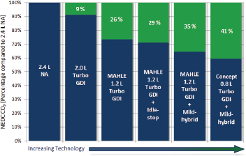
FIGURE 2.4 Fuel consumption reduction of MAHLE’s 30 bar BMEP, turbocharged and downsized engine.
SOURCE: MAHLE (2012). Used with permission of MAHLE Powertrain LLC.
MAHLE is also considering further improvements to the highly turbocharged and downsized engine: further reduction in displacement to 0.8L (67 percent downsizing), exhaust gas recirculation, lean combustion, variable valve trains, and friction reduction. The fuel consumption reductions estimated by MAHLE for these technologies, shown in Figure 2.4, are expected to be significantly less when applied in combination with an already highly downsized and boosted engine. MAHLE did not provide its plans for exploring the benefits of these additional technologies.
In addition to the research program conducted by the MAHLE Powertrain Group, which was directed toward reaching 30 bar BMEP, research programs have also been pursued by other organizations. One example is the experimental Sabre research engine developed by Lotus Engineering, which reached 20 bar BMEP with a 32 percent downsized engine (Coltman 2008). Another example is a General Motors experimental turbocharged engine, which reached
26.4 bar BMEP (Schmuck-Soldan 2011). The Ultraboost project, which had a target of 32.4 bar BMEP with 60 percent downsizing, is discussed separately in the next section.
Ultraboost
A recent paper entitled “Ultraboost: Investigations into the Limits of Extreme Engine Downsizing” provided insights into downsizing from a U.K collaborative project (Turner et al. 2014). In that project, a 60 percent downsized engine (from 5.0L V8 to 2.0L I4) provided a projected 15 percent reduction in NEDC fuel consumption based on steady-state mapping data. An analytical adjustment was made to reduce the measured “high friction” in the engine to match the friction of a “typical boosted engine,” but this adjustment is probably optimistic since this engine operates at much higher boost pressures than “typical boosted engines.” With this analytical adjustment, a 22.6 percent reduction in fuel consumption was estimated. Depreciating this “warm” value by approximately 2.5 percent for the CAFE drive cycle, this engine is estimated to provide approximately a 20 percent reduction in fuel consumption (Ricardo Inc. 2011). In contrast, NHTSA projects 20.6 to 24.6 percent reduction in fuel consumption for the 27 bar BMEP, 56 percent downsized engine.
Several characteristics of this engine are significant. The engine “required” 95 RON gasoline. The compression ratio was reduced from 11.5:1 for the naturally aspirated engine to 9:1 for the Ultraboost engine requiring 95 RON gasoline. The engine had variable cam phasing and cam profile switching. Cooled EGR was used. An engine-driven supercharger (to fill the gap in boost pressure at lower speeds) and a turbocharger were used to obtain the 3.5 bar absolute boost pressure (2.5:1 pressure ratio). Two charge air coolers were used.
Issues with Turbocharged, Downsized Engine
Several remaining technical issues for turbocharged and downsized engines are described below.
Turbocharger Lag
In a turbocharged engine when an increase in torque is commanded, due to the inertia of the turbocharger, the time required to increase boost pressure depends on the increase in rotational speed of turbocharger. Figure 2.5 illustrates the effect of turbocharger lag on the ability of an engine to respond to an increase in torque demand. The curve labeled “Ricardo-assumed” was used by Ricardo for its full system simulation study. Based on EPA’s concern with Ricardo’s assumption, EPA provided Ricardo with its proposed time constants for naturally aspirated and turbocharged engines based on test data. Ricardo subsequently recalculated the acceleration times using EPA’s time constants. As noted, a turbocharged engine may take between 2.5 and 5 seconds to generate the full value of the demanded torque, which can be a source of customer complaint. This issue is being addressed with increasingly smaller turbochargers with reduced rotational inertia.
Reducing turbocharger response times to achieve maxi-
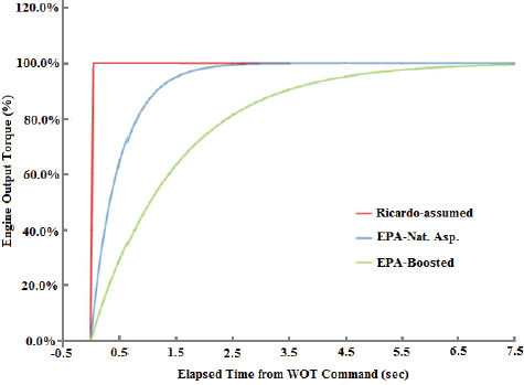
FIGURE 2.5 EPA-proposed time constants and resulting effect on torque rise time for turbocharging.
SOURCE: EPA/NHTSA (2012b).
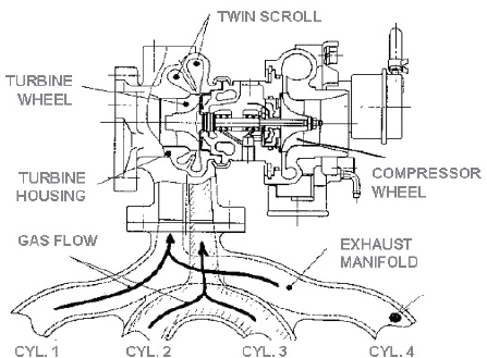
FIGURE 2.6 Twin-scroll turbocharger.
SOURCE: Bundy (2009).
mum torque is an enabler for achieving maximum feasible downsizing of a turbocharged engine while maintaining 0-60 mph acceleration times equal to those of a naturally aspirated engine. Control strategies can also affect transient performance of turbocharged engines. An analytical study of the trade-off between fuel economy and transient performance in turbocharged engines has shown that an engine control strategy optimized for best fuel economy could result in a loss in transient performance (Eriksson 2002). The fuel-optimized strategy keeps the wastegate open to maintain low pressures before and after the engine, whereas the transient performance strategy tries to keep the turbocharged speed as high as possible by closing the wastegate. The typical calibration in production turbocharged gasoline vehicles will strike a balance between the two extreme calibrations based on the analysis of the trade-off between fuel economy and transient response (Gorzelic 2012).
A twin scroll turbocharger has been introduced on some turbocharged, downsized engines to provide higher boost pressures and reduced turbocharger lag times during transients (Bundy 2009). A twin-scroll turbocharger separates the cylinders whose exhaust pulses interfere with each other. The result is superior scavenging of the engine’s cylinders and more efficient delivery of exhaust gas energy to the air charge entering each cylinder. The twin-scroll turbocharger includes not only the complex twin-scroll exhaust gas collectors from the turbine of the turbocharger but also a bifurcated exhaust manifold for the separation of exhaust flowing from the engine, as shown in Figure 2.6. With the increased complexity, the twin-scroll system increases the cost of the turbocharger.
Another approach to eliminating turbocharger lag is to use an engine-driven supercharger in place of the turbocharger. However, the power consumption of the supercharger will diminish the fuel consumption reduction obtained with downsizing unless measures are taken to reduce or eliminate the power consumption, such as with a bypass valve arrangement and/or a clutch mechanism to disengage the supercharger when it is not required at light loads. Several manufacturers have applied superchargers. Audi produces a 3.0L supercharged engine installed in the A6 Quattro, A8, and Q5 vehicles. However, these vehicles do not have larger displacement, naturally aspirated engine counterparts to provide a comparison of the potential of supercharging to reduce fuel consumption relative to turbocharging. Nissan has applied a supercharger with a bypass valve and electromagnetic clutch to a 1.2L three-cylinder gasoline engine with the objective of achieving the lowest fuel consumption in the European B segment market. This engine also benefited from a high compression ratio (13:1), direct injection, and low friction (Kobayashi 2012).
Another approach to eliminating turbocharger lag is to use an electrically assisted turbocharger or supercharger, which is discussed later in this chapter.
Limits of Downsizing - Octane Requirement
Fuel octane requirements for high BMEP engines remain a concern. EPA and NHTSA have proposed the use of cooled EGR to reduce the octane requirement of 24 and 27 bar BMEP engines. Limited results on the ability of cooled EGR to reduce the octane requirements of engines are available. Southwest Research Institute (SwRI) has found that in a modern GDI engine every 10 percent increase in EGR can
provide about 1 compression ratio increase in knock-limited BMEP (Alger et al. 2012). Instead of reducing compression ratio, EGR could be used to reduce the octane requirement, with estimates ranging from approximately 2.5 RON (Leone 2014) to 5 RON (Heywood). Unlike using higher octane fuel to control knock, using EGR to control knock slows the combustion process, resulting in less complete combustion and higher exhaust temperatures, which may present durability concerns.
Some vehicle manufacturers and suppliers are conducting research on the effectiveness of cooled EGR for reducing octane requirements in high BMEP engines. However, results from their research were not available to demonstrate that EGR could reduce the octane requirement to 91 RON in a high BMEP engine. Many manufacturers are members of the SwRI High-Efficiency, Dilute, Gasoline Engine (HEDGE) consortium, which is conducting research on cooled EGR. One manufacturer plans to specify premium fuel for its turbocharged, downsized engines, since it found that the use of cooled EGR is not adequate to facilitate operation on 91 RON fuel. Some European manufacturers also specify premium fuel for turbocharged engines. Specifying premium fuel for turbocharged downsized engines will raise the cost of operation for the consumer.
Several vehicle manufacturers commented on the limitations for turbocharging and downsizing. They said that 50 percent downsizing and 25 bar BMEP were the limits due to NVH and knock limits, assuming the use of regular grade gasoline. However, a few manufacturers indicated that higher BMEP levels would require 100 RON gasoline, which is not currently available in the United States. These manufacturers were doubtful that EGR was a sufficient enabler to reach higher BMEP levels. Another vehicle manufacturer indicated that further fuel consumption reductions could not be obtained with downsizing beyond approximately 50 percent.
Limits of Downsizing - Preignition
Preignition and detonation or knock are concerns with downsized, turbocharged engines. MAHLE illustrated these limits at high BMEP levels in Figure 2.7, which shows that the spark timing range for acceptable operation between preignition and detonation limits is significantly reduced at higher BMEP levels. SwRI has identified low-speed preignition (LSPI), which can seriously damage engine parts or cause complete engine failure, as a major impediment to aggressive engine downsizing and downspeeding to reduce fuel consumption (Alger 2013). SwRI has demonstrated that LSPI can be suppressed in turbocharged engines by using cooled EGR and advanced ignition timing. SwRI launched a Preignition Prevention Program (P3) consortium in 2010 that is looking at the root causes and at fuels and lubricants to discover ways to suppress LSPI.
LSPI is abnormal combustion at low engine speeds and high loads. It is characterized by preignition that leads to high cylinder pressure and heavy knock. LSPI often occurs in multiple cycles and usually oscillates between preignition and spark ignition. LSPI is typically measured in the range of fewer than six preignition events per 30,000 engine cycles. In the case of the SwRI engine, 15 percent cooled EGR was found to eliminate LSPI completely (Alger 2010). SwRI has hypothesized that low-speed preignition results from the oil and fuel mixture being ejected from the crevice volumes of the piston and igniting the main charge. To address this cause,
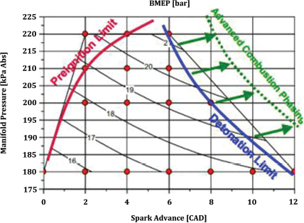
FIGURE 2.7 Preignition and detonation limits for a turbocharged, downsized engine.
SOURCE: Blaxill (2012). Used with permission of MAHLE Powertrain LLC.
the new GF-6 oil rating is being developed to protect against LSPI (see earlier section on Low Friction Lubricants).
Higher-Temperature Turbochargers
Turbochargers with a 950oC temperature limit, as assumed by EPA and NHTSA, may not be sufficient for achieving the full potential fuel consumption reductions or the largest amount of downsizing (NHTSA/EPA 2014). Engine exhaust temperatures increase with load and can easily exceed 950oC before full load is reached. To protect the turbocharger, fuel enrichment is often used, which can deteriorate the fuel consumption of the vehicle. To extend the load range at a stoichiometric air/fuel ratio, higher-temperature turbochargers with a capability of 1050oC are being applied (Merkelbach 2009; Bickerstaff 2012). Achieving this temperature capability requires expensive alloys (MAR M246 nickel-cobalt-tungsten superalloy) that significantly increase the cost of the turbocharged engine. As increased levels of downsizing are applied, increasing turbocharger temperature capabilities are expected to be required.
Transmissions
Torsional dampers are required between the engine and transmission to decouple the engine rotational irregularities and reduce vibration and noise levels in the transmission. The task and complexity, and therefore cost, increase as one downsizes from V8 to V6, V6 to I4, and I4 to I3 engines. I3 engines will require the most expensive damper. Increasingly complex damping systems could include single- or two-stage dampers, a dual-mass flywheel, and/or a torque converter damper.
Noise, Vibration, and Harshness
Vehicle modifications will be required to isolate downsized engines from the passenger compartments. These modifications may consist of complex engine mounting systems and engine and turbocharger noise isolation.
Cooled Exhaust Gas Recirculation
EGR can increase the efficiency of gasoline engines through several mechanisms:
- Reduced throttling losses with the increased flow of air and EGR into the cylinders;
- Reduced heat rejection due to the lowered peak combustion temperatures;
- Reduced chemical dissociation, with the lower peak temperatures resulting in more of the released energy near top dead-center; and
- Higher specific heat ratio (gamma), which increases the work done on the piston.
The potential fuel consumption reduction provided by cooled EGR was estimated for each of these mechanisms. The introduction of 20 percent EGR at a part load condition in a conventional engine would increase manifold pressure by 20 percent, which would reduce pumping losses by approximately 10 percent. However, by adding EGR to an engine with VVT, continuously variable valve lift, and turbocharging and downsizing, the pumping losses will already be very low, so adding EGR is not expected to provide significant additional reductions in pumping losses. Pumping losses could possibly increase due to the requirement for higher exhaust pressure to achieve the required EGR flow. EGR will increase the specific heat ratio, which is estimated to provide a 1.5 reduction in fuel consumption. Adding in benefits from reduced heat rejection, reduced dissociation losses and minor reductions in pumping losses would result in about 2.5 percent reduction in fuel consumption, which is 1 percentage point lower compared to the 3.5 percent effectiveness estimated by NHTSA, as shown previously in Table 2.17. MAHLE Behr recently reported that cooled EGR could provide about a 2 to 4 percent reduction in fuel consumption at light to moderate loads (Morey 2014).
A supplier confirmed that NHTSA’s estimate of $305 total cost, or $212 direct manufacturing costs, for the dual-loop, high- and low-pressure, cooled EGR system is in the appropriate range. Water condensation problems, which would require a sophisticated trap and drain system, would increase this cost. However, this supplier felt that single-loop EGR systems would likely be the preferred approach.
A supplier suggested that high dilution rates with EGR might require upgraded ignition systems to achieve acceptable combustion stability (low coefficient of variation of IMEP). Today’s ignition systems produce approximately 40 mJ of energy, but high rates of EGR may require more than double the energy, which would necessitate a new ignition system with an unknown incremental cost.
Summary of Fuel Consumption Reductions and Costs of Turbocharged, Downsized Engines
A summary of the estimated fuel consumption reductions and associated direct manufacturing costs for turbocharging and downsizing (TRBDS) is shown in Table 2.18. The committee’s high effectiveness estimates of turbocharged, downsized engines agree with NHTSA’s estimates, while the committee’s low effectiveness estimates are lower than NHTSA’s estimates by the amounts shown previously in Table 2.17, which were relative to the baseline engine. For the incremental estimates relative to the previously applied SI engine technologies, the ratio of NHTSA’s incremental to baseline effectiveness was applied to the committee’s baseline estimates to provide the committee’s incremental estimates shown in Table 2.18.
The committee’s most likely low estimate of incremental direct manufacturing cost (DMC) for turbocharged, down-
| Turbocharged, Downsized Engine Technology | NRC Estimated Most Likely Fuel Consumption Reduction (%)a,b | NHTSA Estimated Fuel Consumption Reduction (%)a | NRC Estimated Most Likely 2025 MY DMC Costs (2010$)a | NHTSA Estimated 2025 MY DMC Costs (2010$)a | |||||||||||||||
| 18 bar BMEPb | 11.1 - 14.9 | 12.1 - 14.9 | 245 - 282 | 245 | |||||||||||||||
| Incrementalc | 7.7 - 8.3 | 8.3 | 245 - 282 | 245 | |||||||||||||||
| 24 bar BMEPb | 14.4 - 20.1 | 16.4 - 20.1 | 400 - 437 | 400 | |||||||||||||||
| Incrementalc | 3.2 - 3.5 | 3.5 | 155 | 155 | |||||||||||||||
| 24 bar BMEP w/CEGRb | 16.3 - 23.0 | 19.3 - 23.0 | 580 - 617 | 580 | |||||||||||||||
| Incrementalc | 3.0 - 3.5 | 3.5 | 180 | 180 | |||||||||||||||
| 27 bar BMEP w/CEGRb | 17.6 - 24.6 | 20.6 - 24.6 | 890 - 927 | 890 | |||||||||||||||
| Incrementalc | 1.4 | 1.4 | 310 | 310 | |||||||||||||||
| Other Possible Costs | |||||||||||||||||||
| Turbocharger (Upgrade to 1050 °C) | 25 - 75 | ||||||||||||||||||
| Ignition Upgrade (for EGR) | 20 - 70 | ||||||||||||||||||
| Transmission (Upgrades for 3 cyl) | 0 - 50 | ||||||||||||||||||
| Vehicle Integration (NVH, Thermal Mgmt.) | 0 - 25 | ||||||||||||||||||
a Baseline is 12 bar BMEP natural aspirated engine.
b Relative to baseline with fixed valve timing and lift, PFI.
c Incremental to all previous SI technologies (LUB, EFR, DCP, CVVL, SGDI, TRBDS as applicable).
d Ranges are shown for all vehicle classifications.
SOURCE: EPA/NHTSA (2012b) and committee.
sized engines match NHTSA’s projections, while the committee’s most likely high costs are higher than NHTSA’s projections due to increased estimated costs for some of the system components, including the turbocharger and charge air cooler. Other possible costs are noted in Table 2.18, which do not appear to have been considered by NHTSA; they include upgrades for higher temperature capability turbochargers, ignition system upgrades to provide adequate ignition energy with cooled EGR, transmission upgrades, particularly with three-cylinder engines, and vehicle integration components for NVH reduction and thermal management.
DOE Research Projects on Turbocharged and Downsized Engines
DOE currently has programs with Ford, General Motors, and Chrysler to demonstrate a 25 percent improvement in fuel economy while achieving Tier 2 Bin 2 emissions requirements with downsized, boosted engines and a variety of other technologies, including lean combustion, cooled EGR, advanced ignition systems, and friction reduction technologies. These programs are described in Appendix K. Final results from these programs are not yet available.
Accessories
Approximately 2.8 percent of the fuel consumption (equal to 1 percent of the fuel energy) is required to drive the accessories, most of which are required by the engine when tested on the CAFE drive cycle. This estimate can be derived from Figure 2.1 by dividing the 1 percent of the fuel energy shown for accessory loads by the ITE of 36 percent. Additional discussion of vehicle accessories such as air conditioning is contained Chapter 6, “Non-Powertrain Technologies.” NHTSA accounts for engine-required accessories and vehicle accessories in the combined category of Improved Accessories, Levels 1 and 2 (IACC1 and IACC2). NHTSA has defined the improved accessories as follows:
- IACC1: electric water pump, electric cooling fan, high efficiency alternator and
- IACC2: mild alternator regenerative braking (specifically excluded are an electric oil pump and electrically driven air conditioner compressor).
NHTSA estimated the following fuel consumption reductions for the improved accessories (EPA/NHTSA 2012):
- IACC1: 0.91-1.61 percent (relative to EPS) and
- IACC2: 1.74-2.55 percent (relative to IACC1).
The estimated fuel consumption reductions with improved accessories for each category are shown in Table 2.19. The following steps are shown in the table to estimate the fuel consumption reduction for the improved accessories: (1) estimate the engine BMEP required for each accessory, (2) replace mechanically driven accessories with electrically driven accessories (which increases power requirements due to the electric motor and alternator inefficiencies relative to the mechanical drives), (3) apply on-demand operation of the electrically driven accessories, and (4) replace DC brush motors with brushless motors for improved efficiency. The alternator efficiency was improved from 65 percent to 70 percent as specified by NHTSA. The fuel consumption reduction for the improved accessories level 1 was estimated to be 1.1 percent, which is at the low end of the range of NHTSA’s estimates. For improved accessories level 2, the fuel consumption reduction was estimated to be 2.0 percent, which was also within the range of NHTSA’s estimates.
Water Pump
An electric water pump can be controlled to provide the flow of coolant through the engine to maintain required engine temperatures. An electric water pump will be more efficient than one that is belt driven at a fixed ratio of engine speed, which is independent of the coolant flow required. A turbocharged engine with an electrically-driven water pump can continue to run the water pump to cool the turbocharger even if the engine is shut off. As an example, BMW uses electrically-driven water pumps on most of its mainstream turbocharged engines. Concern about failure modes with an electric water pump was reported.
Cooling Fan
Most front-wheel-drive cars and many rear-wheel-drive vehicles currently use electrically driven cooling fans. Direct current (DC) motor-driven cooling fans have a wide range of maximum wattages in light-duty vehicles. For a 400 W cooling fan, assuming 70 percent alternator efficiency, a load of 571 W, or 0.75 horsepower, would be applied to the engine at maximum cooling conditions. Cooling fan loads can be reduced with two-speed or infinitely variable speed operation, in addition to shutting them off when not needed. Two speeds were often achieved by using a resistor to reduce voltage to the motor. Infinitely variable speeds are provided by a pulsewidth modulated controller, which reduces the amount of energy wasted.
Oil Pump
Fixed-displacement oil pumps are used on most vehicles today. Typically, these pumps are oversized in order to operate under harsh engine operating conditions. They typically consume more power and deliver significantly higher oil pressures and flow rates than needed. They contain pressure-relief valves to avert excessively high oil pressures. Since they consume significant amounts of energy at high oil flow rates, these designs are inefficient.
Variable-displacement oil pumps help keep these energy losses to a minimum. Active control matches the oil flow and pressure to the engine needs. It eliminates excess oil flow, substantially reduces the parasitic load on the engine, and ultimately saves fuel. In variable-displacement pumps, changing the displacement volume controls the flow rate. Vane-pump designs have hydraulic and electrical controls and actuators that move the pump housing and vary the eccentricity of the rotor. Electronic controls vary the pressure set points as dictated by operating conditions. Some vehicle manufacturers adopted these kinds of pumps starting in 2011, using them in engines for high-end vehicles in Europe. Recently, Chrysler introduced a variable-displacement oil pump on its 3.6L DOHC V6 engine, which is used in about a third of Chrysler products (Witzenburg 2013).
Although not considered by NHTSA, electrified engine oil pumps provide further opportunities to reduce fuel consumption.
Brushless Motors
Brushless motors are replacing brushed DC motors. Brushless motors are typically 85-90 percent efficient, whereas brushed DC motors are 75-80 percent efficient (Quantum Devices 2013). The higher efficiency of a brushless motor would result in a 12 percent reduction in electrical power required. However, brushless motors are more expensive than brushed motors, partly due to their control requirements. One vehicle manufacturer is planning to apply brushless motors to its entire product line.
Summary of Effectiveness of Spark Ignition Engine Technologies
EPA and NHTSA expended significant effort and resources in estimating the fuel consumption reductions for a range of SI engine technologies. To accomplish this task, they used full system simulations, response surface modeling, and the LPM together with literature reviews, data from vehicle manufacturers and suppliers, and expert opinions. From this input, EPA and NHTSA developed the estimates of fuel consumption reductions shown in the TSD. Since the committee did not have the resources to develop similar estimated fuel consumption reductions, the following approaches were used to examine the Agencies’ estimates and to develop the committee’s estimates of most likely effectiveness values: fundamental technical analysis, literature reviews, full system simulations, EPA certification data, expert input from vehicle manufacturers and others, and the committee’s expertise.
A summary of the committee’s low and high most likely
| Engine Required Accessories Included in IACC Category | Mechanical Load MEP (kPa)a | Electrical Load (watts) | Baseline percent of CAFE Load IMEP (%)b | Modified percent of CAFE Load IMEP (%)b | Percent of CAFE load IMEP with Electrification (%)f | Percent of CAFE Load IMEP with 25% On-Demand Operation (%) | Percent of CAFE Load IMEP with Brushless Motors (%)g | Modified percent of Total FCd | Reduction in FC (from baseline to modified) (%) | ||||||||||
| IACC 1 | |||||||||||||||||||
| Water Pump | Mechanical | 7.0 | 1.4 | ||||||||||||||||
| Electrical - 70% Alt/Motor Eff | 2.2 | 0.55 | 0.48 | 0.48 | 0.92 | ||||||||||||||
| Cooling Fanc | Electrical | 400 | |||||||||||||||||
| Mechanical - 65% Alt Eff, 25% Duty Cycle | 1.04 | 0.21 | 0.21 | ||||||||||||||||
| Mechanical - 70% Alt/Motor Eff, 25% Duty Cycle | 0.9 | 371 | 0.18 | 0.18 | 0.16 | 0.16 | 0.05 | ||||||||||||
| Alternatord | Mechanical | 10.0 | 2.0 | ||||||||||||||||
| Electrical Output - 65% Alt Eff | 1.3 | ||||||||||||||||||
| Mechanical - 70% Alt Eff | 1.9 | 0.14 | |||||||||||||||||
| Sub-Total | 3.6 | 1.1 | |||||||||||||||||
| IACC2 | |||||||||||||||||||
| Regen Braking | 80% of Remaining Electric Power from Regeneration | 2.5 | 0.5 | 2.0 | |||||||||||||||
| Total | 3.1 | ||||||||||||||||||
a Heywood (1988), pp. 739-740.
b Heywood (1988), p. 825. Full load IMEP = 1000 kPa or 14.5 bar, CAFE cycle IMEP = 500 kPa (7.25 bar).
c 400 watt electric fan, 25% on-demand, 0.4 kW/(150 kW engine × 1500 rpm/6000 rpm) × 500kPa × .25 =2.7 kPa.
d Alternator for engine electrical power (ignition, controls) only.
e Assuming 100% of fuel produces 100% of CAFE cycle IMEP.
f Assuming 70% motor efficiency, 70% alternator efficiency.
g Assuming 12% efficiency improvement for brushless motors.
NOTE: Grey color indicates input for the calculations in the table.
effectiveness estimates for SI engine technologies are compared to NHTSA’s estimates for an I4 engine in Table 2A.3 (Annex at end of this chapter). The committee’s estimated effectiveness values for I4 DOHC, V6 DOHC, and V8 OHV engines in midsize cars, large cars, and large light trucks, respectively, are provided in Table 2A.1 (Annex). The committee’s estimates of effectiveness agreed with many of NHTSA’s estimates. For several technologies, the committee’s high estimates agreed with NHTSA’s estimates, while the low estimate for the 18 bar BMEP engine was 1 percentage point lower than the high estimate of 14.9 percent; for the 24 bar BMEP engine, the low estimate was 2 percentage points lower than the high estimate of 20.1 percent; and, for cooled EGR, the low estimate was 1 percentage point lower than the high estimate of 3.5 percent. To achieve these estimates, some of the technologies will require new developments, such as a new low-friction lubricant meeting a new specification for 0W-12 oil, which is under development, and higher BMEP engines with cooled EGR.
Costs of Spark Ignition Engine Technologies
Teardown Cost Studies of Turbocharged, Downsized Engines
Of all the SI engine technologies identified by NHTSA, teardown cost studies by FEV were conducted only for turbocharging and downsizing (TRBDS), which included SGDI technologies. These teardown cost studies assessed the direct manufacturing costs of vehicle technologies. They were conducted by FEV for the following three turbocharging and downsizing cases:
- SGDI and turbocharging with engine downsizing from a DOHC four-cylinder engine to a small DOHC four-cylinder engine.
- SGDI and turbocharging with engine downsizing for a DOHC V6 engine to a DOHC four-cylinder engine.
- SGDI and turbocharging with engine downsizing from a SOHC three-valve/cylinder V8 engine to a DOHC V6 engine.
EPA extrapolated the results of these studies to several other downsizing scenarios.
Each of the FEV teardown cost studies developed incremental costs associated with 17 subsystems. These subsystem costs were assigned to three major technologies under consideration: SGDI, turbocharging, and engine downsizing. In some cases, a portion of the overall cost result was distributed over several technologies (Olechiw 2009). Table 2.20 summarizes the results of binning the costs.
Teardown costs of the three most costly subsystems provide insight into these overall costs. The three most costly subsystems are the following (FEV Inc. 2009):
- Induction air charging subsystem,
- Fuel induction subsystem, and
- Engine management, engine electronic and electrical subsystem.
A further breakdown of these subsystem costs in Table 2.21 illustrates the most costly components in these subsystems. Using the 2.4L I4 NA to 1.6L I4 TC as an example, these three subsystems comprise nearly 80 percent of the total cost of turbocharging and downsizing technology.
The vehicle manufacturers and suppliers that the NRC committee met with were asked to comment on all of the technology costs, with particular attention to the teardown costs. The following comments were received:
- The cost of a turbocharger assembly could be up to twice the cost shown in Table 2.21 depending on the materials required to achieve a specified temperature capability and the boost control system (wastegate, variable geometry turbine). EPA and NHTSA have indicated that they did not rely on any turbocharger system operating above 950°C (NHTSA/EPA 2014), although, as described earlier, many systems are currently in production with 1050°C capability.
- The charge air cooler and exhaust manifold could have significantly higher costs than shown in the cost teardown studies.
- The powertrain control module (PCM) costs could benefit from further refinement, as was noted in the peer review of the pilot EPA/FEV cost study.
- Indirect costs applied to the direct manufacturing costs from these studies warrant revision upward due to concerns with engineering research and development for the required pace of technology introductions, testing capacity constraints, sustainability of vehicle segments, cost of capital, and stranded investment.
Direct Manufacturing Costs
The direct manufacturing costs of technologies for SI engines were estimated using one of the following processes:
- EPA and NHTSA developed direct manufacturing costs of several technologies based on FEV teardown cost studies. These studies were critically reviewed. Updates or adjustments were applied, as required, to the teardown cost studies based on the committee’s expertise and judgment that incorporated a review of available information, including other cost data from published studies, input from vehicle manufacturers and suppliers, and a review of retail prices adjusted to reflect direct manufacturing costs.
- For technology costs that were not supported by teardown cost studies, the committee identified subsystem and major components of the technology similar to the
TABLE 2.20 Results of Binning Costs
| Engine | Incremental to | Total Incremental Costs ($) | SGDI ($) | Turbocharging ($) | Downsizing ($) | ||||||||||||||
| 1.6L I4 Turbo SGDI | 2.4L I4 MPFI DOHC | 532 | 213 | 404 | (85) | ||||||||||||||
| 2.0L I4 DOHC SGDI | 3.0L V6 MPFI V6 DOHC | 69 | 213 | 404 | (547) | ||||||||||||||
| 3.5L V6 DOHC Turbo SGDI | 5.4L V8 MPFI three-valve SOHC | 846 | 321 | 681 | (155) | ||||||||||||||
SOURCE: Olechiw (2009).
TABLE 2.21 High-Cost Components in High-Cost Subsystems for Turbocharged and Downsized Engines
| Subsystem | Net Cost Impact to OEM ($) | Net Cost Impact to OEM ($) | Net Cost Impact to OEM ($) | ||||||||||||||||
| Induction Air Charging Subsystem | 2.4L I4 NA to 1.6L I4 TC | 3.0L V6 NA to 2.0L I4 TC | 5.4L V8 SOHC to 3.5L V6 DOHC | ||||||||||||||||
| Turbocharger assembly | 151.85 | 169.89 | 329.82 | ||||||||||||||||
| Charge air cooler | 18.65 | 20.92 | 35.61 | ||||||||||||||||
| Tube assembly | 18.76 | 53.93 | 42.61 | ||||||||||||||||
| Engine and vehicle assembly of air induction components | 25.70 | 25.67 | 27.35 | ||||||||||||||||
| Multiple components (<$15 each) | |||||||||||||||||||
| Total Subsystem | 258.89 | 280.70 | 448.79 | ||||||||||||||||
| Fuel Induction Subsystem | Net Cost Impact to OEM ($) | Net Cost Impact to OEM ($) | Net Cost Impact to OEM ($) | ||||||||||||||||
| High pressure pump | 69.61 | 64.90 | 81.12 | ||||||||||||||||
| Fuel injectors Solenoid 7 hole | 17.42 | 5.10 | 15.15 | ||||||||||||||||
| Fuel Rails | 14.93 | 10.77 | 15.15 | ||||||||||||||||
| Multiple components (<$15 each) | |||||||||||||||||||
| Total Subsystem | 107.30 | 84.76 | 124.57 | ||||||||||||||||
| Engine Management, Engine Electronic and Electrical Subsystem | Net Cost Impact to OEM ($) | Net Cost Impact to OEM ($) | Net Cost Impact to OEM ($) | ||||||||||||||||
| Powertrain Control Module (PCM) - Hardware | 40.00 | 40.00 | 60.00 | ||||||||||||||||
| Multiple components (<$15 each) | |||||||||||||||||||
| Total Subsystem | 56.61 | 21.57 | 70.15 | ||||||||||||||||
SOURCE: FEV Inc. (2009).
process used in the teardown cost studies. Costs were estimated for these subsystems and components by applying the committee’s expertise, which incorporated a review of available information, including NHTSA’s estimates and associated references, other cost data from published studies (such as shown in Table 2.29), input from vehicle manufacturers and suppliers, and a review of retail prices adjusted to reflect direct manufacturing cost.
Examples of both of these processes are provided in this section.
An example of the process for estimating direct manufacturing costs for the intake cam phasing system is shown in Table 2.22. The subsystems and components required for this technology installed on an engine are listed, together with estimated costs and comments on the sources of these costs. Also shown for comparison is EPA’s and NHTSA’s cost estimate. Since the cost estimates were generated for the 2012 MY, learning factors, as specified by NHTSA, were applied to the direct manufacturing costs to provide 2017 MY estimates in 2010 dollars, as shown in the table and the 2025 MY costs shown in later tables (EPA/NHTSA 2012b). NHTSA’s learning factors include the effects of accumulated production volume and innovations in design and manufac-
TABLE 2.22 Example of Direct Manufacturing Cost (DMC) Estimates for Intake Cam Phasing (ICP) System
| I4 Engine | ||
| Technology | DMC ($) | Source of Costs |
| Intake Cam Phasing (ICP) | ||
| Cam phaser (1 per intake camshaft) | 21.90 | Committee’s expertise/judgement |
| Up-sized oil pump | 1.80 | FEV: Half of cost of turbo oil pump upgradea |
| Oil control valve - spool for filling and emptying | 12.00 | Committee’s expertise/judgement |
| PWM output from low side driver of ECM | 4.00 | Committee’s expertise/judgement |
| Oil drillings - inlet and return | 1.00 | Committee’s expertise/judgement |
| Position feedback sensor | 4.00 | Committee’s expertise/judgement |
| Cam phase trigger wheel - 4 pulses per revolution | 1.00 | Half of FEV cost of camshaft sprocketa |
| Revised cam driver cover | 2.00 | Committee’s expertise/judgement |
| Wiring and connectors | 1.79 | FEV: 40% of cost of wiringa |
| Total: 2012 MY cost in 2010$ | 49.49 | |
| DMC Learning Type 12, 2012 to 2017 Learning Factor - 0.86 | ||
| Total: 2017 MY direct manufacturing cost (2010$) | 42.56 | 15% increase |
| Reference: EPA/NHTSA direct manufacturing costs 2017 MY (2010$) | 37.00 | |
a FEV teardown cost study for turbocharged downsized engines.
SOURCE: NRC Committee; FEV (2009); EPA/NHTSA (2012b).
turing. Further discussion of learning factors is contained in Chapters 7 and 8. In the case of intake cam phasing shown in the table, the direct manufacturing cost was estimated to be 15 percent higher than EPA’s and NHTSA’s estimate (Martec 2008; EPA/NHTSA 2010). The committee took this computed cost to be the high most likely value and retained the Agencies’ cost as the low most likely value.
Another example of the process for estimating direct manufacturing costs for the continuously variable valve lift system is shown in Table 2.23. In this case, the direct manufacturing cost was also estimated to be 15 percent higher than EPA’s and NHTSA’s estimate (EPA/NHTSA 2010). The committee took this computed cost to be the high most likely value and retained the Agencies’ cost as the low most likely value.
An example of the process for assessing direct manufacturing costs for turbocharging and downsizing is shown in Table 2.24. In this case, direct manufacturing costs are based on the FEV teardown cost study so only selected subsystems and components were examined for possible updates and adjustments to costs. Two key components, the turbocharger assembly and the intercooler, were examined, and the resulting modifications to the costs, together with the sources of the revised costs, are shown in the table. For the case of turbocharging and downsizing, this approach leads to an estimate of direct manufacturing cost that is 15 percent higher than NHTSA estimates. The committee took this computed cost to be the high most likely value and retained the Agencies’ cost as the low most likely value.
Indirect Costs: Estimation of Components for ICP
EPA, RTI International, and the Transportation Institute of the University of Michigan developed the concept of Indirect Cost (IC) multipliers to support the evaluation of costs for regulatory actions (Rogozhin et al. 2009). Chapter 7 discusses indirect cost multipliers in greater detail. For medium-complexity technology, typical of many SI engine technologies, the research and development (product development) costs were shown in the foregoing reference to amount to 5 percent of the indirect costs. The committee examined the details of the product development costs to implement intake cam phasing (ICP) technology as an example and found that an upward adjustment of the indirect cost multipliers was appropriate.
NHTSA considered ICP as a low-complexity technology with an indirect cost multiplier of 1.24, which would be comparable in complexity to the application of low rolling resistance tires. The product development steps required for ICP would consist of the following: (1) installation of the new hardware in the engine, (2) software development, (3) engine mapping for initial calibration optimization, (4) calibration development in the vehicle at all environmental conditions, (5) durability development, and (6) certification from EPA and the California Air Resources Board (CARB).
| I4 Engine | ||
| Technology | DMC ($) | Source of Costs |
| Continuous Variable Valve Lift (CVVL Similar to Valvematic) | ||
| Intermediate shaft with finger follower | 35.85 | Committee’s expertise/judgement |
| Internal shaft for roller finger followers | 35.85 | Committee’s expertise/judgement |
| Roller finger followers - 8 required | 34.02 | Committee’s expertise/judgement |
| Cylinder head casing with boring and shaft bearing caps | 82.75 | FEV: Adjusted cost for SGDI cyl head modifa |
| Electric motor actuator | 29.84 | Committee’s expertise/judgement |
| PWM output from low side driver of ECM | 4.00 | Committee’s expertise/judgement |
| ECU input for angle sensor | 1.00 | Committee’s expertise/judgement |
| Angle position feedback sensor | 4.00 | Committee’s expertise/judgement |
| Revised valve cover | 3.00 | Committee’s expertise/judgement |
| Wiring and connectors | 1.79 | FEV: 40% of cost of wiringa |
| Total: 2012 MY cost in 2010$ | 232.10 | |
| DMC Learning Type 12, 2012 to 2017 Learning Factor = 0.86 | ||
| Total: 2017 MY direct manufacturing cost (2010$) | 199.61 | 15% increase |
| Reference: EPA/NHTSA direct manufacturing costs 2017 MY (2010$) | 174.00 | |
a FEV teardown cost study for turbocharged downsize engine.
SOURCE: NRC committee; FEV (2009); EPA/NHTSA (2012b).
| I4 Engine | |||||||||||||||||||
| Technology | EPA/NHTSA DMC ($) | Adjustment ($) | Revised DMC ($) | Source of Costs | |||||||||||||||
| Turbocharging and Downsizing (TRBDS1) 18 bar BMEP 33% Downsizing | |||||||||||||||||||
| Overall DMC | 335.00 | FEV teardown cost studya | |||||||||||||||||
| Selected Subsystems and Components | |||||||||||||||||||
| Induction Air Charging System | |||||||||||||||||||
| Turbocharger Assembly | 152.00 | 38.00 | 190.00 | Committee’s expertise/judgement | |||||||||||||||
| Charge air cooler | 19.00 | 11.00 | 30.00 | Committee’s expertise/judgement | |||||||||||||||
| Total: 2012 MY cost in 2010$ | 335.00 | 49.00 | 384.00 | DMC Learning Type 11, 2012 to 2017 Learning Factor = 0.86 | |||||||||||||||
| Total: 2017 MY direct manufacturing cost (2010$) | 288.10 | 330.24 | 15% increase | ||||||||||||||||
| Reference: EPA/NHTSA direct manufacturing costs 2017 MY (2010$) | 288.00 | ||||||||||||||||||
a FEV teardown cost study for turbocharged, downsized engine.
SOURCE: NRC committee; FEV (2009); EPA/NHTSA (2012b).
This is considerably more complex and more labor- and time-intensive than the addition of low resistance tires and would require confirmation of performance and durability. Consequently, the assignment of medium complexity to the ICP was considered to be more appropriate as a starting point in the analysis of indirect costs for this technology. NHTSA assigned medium-complexity indirect cost multipliers (ICMs) to most other SI engine technologies requiring the product development process described above.
A detailed review of indirect costs for the development and application of powertrain technologies was undertaken by the committee, using ICP as an example. The product development costs for the ICP technology, based on the above steps, were estimated in Table 2.25 to be $8.60 by amortizing the total product development cost over a 5-year period for an annual production volume of 50,000 units, which was assumed to be typical of a specific vehicle/engine combination application. The costs shown in Table 2.25 relate only to the application of the ICP technology to a specific vehicle/engine configuration and do not include engine design and development costs, which would be included in direct manufacturing costs. However, with more rapid introduction of technologies, the 5-year period can often be reduced significantly, which would increase the indirect cost per vehicle, since the indirect cost would be be amortized over a shorter time period.
The following adjustments to the IC multiplier resulting from the product development costs for the ICP technology found in Table 2.25 are shown in Table 2.26 and described below.
- NHTSA’s indirect cost multiplier for the medium-complexity ICP technology is 1.39, which yields an indirect cost of $22.54 (0.39 × $57.79) for the case of ICP.
- The indirect cost multiplier for medium-complexity technology would allocate an amount equal to 5 percent of the indirect cost to product development, which equals $1.13 (0.05 × $22.54).
- An estimated product development cost of $8.60 is shown in Table 2.26. Therefore, an increased indirect cost of $7.47 ($8.60 − 1.13) would be incurred for the ICP technology.
- Adding the incremental indirect cost of $7.47 to the indirect cost of $22.54 yields a revised indirect cost of $30.01, which is equal to 52 percent of the direct manufacturing cost ($30.01/$57.79).
An example of applying ICP to a V6 engine is shown in Table 2.27. ICP applied to a V6 engine has double the direct manufacturing cost of applying ICP to an I4 engine. However, the moderate increases in the product development costs for the V6 application in the areas of engine design (for interfacing with each specific vehicle) and prototype hardware costs result in an increase in the ICM to 1.46 from NHTSA’s estimated value of 1.39.
There are several reasons the committee determined that these indirect costs were appropriately associated with technologies providing fuel consumption reductions. These indirect costs are associated with the addition of an individual technology providing fuel consumption reductions. These technologies would be applied not in the reference case defined by EPA and NHTSA but instead only in the control case. And these technologies have been applied individually only after a technology has been developed and proven in research and advanced development. For example, DCP might be rolled out in a new model year with VVL being rolled out separately in a subsequent model year after the technology has been developed. Under this deployment scenario, assigning these costs to an individual technology is generally
TABLE 2.25 Product Development Cost Estimates for Intake Cam Phasing Technology Example
| Indirect Costs for ICP Example | |
| Hardware and Labor | Cost ($) |
| Engine design for ICP - 1 person-year | 150,000 |
| Software development - 1 person-year | 150,000 |
| Calibration development - 2 person-years | 300,000 |
| Dynamometer operation (engineer, technicians) | 250,000 |
| Chassis dynamometer operation (engineer, technicians) | 250,000 |
| Prototype engines and control hardware | 150,000 |
| Prototype vehicles (2 calibration, 2 durability) | 400,000 |
| Technician - 2 person-years | 200,000 |
| Durability testing - 1 person-year | 150,000 |
| Certification - 1 person-year (engineer, technicians) | 150,000 |
| Total | 2,150,000 |
| Total IC costs 2012MY in 2010$ (amortized over 50,000 units for 5 years) | 8.60 |
| Reference EPA/NHTSA Indirect Cost Process | Revised Product Development Cost ($) | Incremental Cost ($) | Revised IC | ||||||||||||||||
| Direct Manufacturing Cost (DMC) | $57.79 | ||||||||||||||||||
| Indirect Cost Multiplier (ICM) = DMC+IC)/DMC | 1.39 | 1.52 | |||||||||||||||||
| Indirect Cost (IC) | $22.54 | $7.47 | $30.01 | ||||||||||||||||
| Product Development Cost Percent of IC | 5% | ||||||||||||||||||
| Product Development Cost | $1.13 | $8.60 | $7.47 | ||||||||||||||||
appropriate, although there are some opportunities for combining the application of technologies, such as combining SGDI with turbocharging and downsizing. In such a case, many of the unique elements of the indirect costs for SGDI, particularly prototype hardware, software, and calibration, would be included in a consolidated program. And the committee understands that, with the increasing stringency of the CAFE/GHG standards and with further development of new technologies to a production-feasible level, there may be more instances of multiple technologies being introduced with a consolidation of development software and calibration processes.
This analysis used ICP as an example, and there are other insights resulting from the empirical examination of other SI engine technologies and multiple technologies that require the powertrain product development process involving experimental hardware and vehicles, software, calibration, durability testing, and EPA and CARB certification. Due to the uncertainties surrounding the ICMs, the committee generally assessed only the direct manufacturing costs for each technology. Chapter 7 discusses the committee’s concern that an empirical basis for EPA/NHTSA’s indirect cost multipliers is lacking. EPA presented evidence to the committee that, on average, the ICM method resulted in the ratio of total costs to direct manufacturing costs of approximately 1.50, which is consistent with feedback that the committee obtained from several vehicle manufacturers, with the NRC Phase I study, and with NHTSA studies supporting rulemaking prior to the 2012 rulemaking (EPA 2014e).
The committee also is recommending several modifications to the complexity levels assigned by NHTSA to the SI engine technologies, as shown in Table 2.28. The committee recommends that both intake cam phasing and cylinder deactivation be modified to a medium complexity level, rather than the low complexity level assigned by NHTSA, since each of these technologies involves similar product development steps associated with the costs shown in Table 2.25.
TABLE 2.27 Calculation of Revised ICM for Intake Cam Phasing-V6 Engine Technology Example
| Example for ICP for a V6 Engine | |||||||||||||||||||
| Product Development Cost ($) | |||||||||||||||||||
| ICP | $2,150,000 | ||||||||||||||||||
| Incremental Cost for ICP for V6 | |||||||||||||||||||
| Engine Design | $150,000 | ||||||||||||||||||
| Prototype engines and control hardware | $150,000 | ||||||||||||||||||
| Total = | $2,450,000 | ||||||||||||||||||
| Total IC cost per unit in 2010$ | $9.80 | ||||||||||||||||||
| Reference: EPA/NHTSA Indirect Cost Process | Revised Product Development Cost | Incremental Cost (IC) | Revised IC | ||||||||||||||||
| Direct Manufacturing Cost (DMC) | $115.58 | ||||||||||||||||||
| Indirect Cost Multiplier (ICM) = (DMC+IC)/DMC | 1.39 | 1.46 | |||||||||||||||||
| Indirect Cost (IC) | $45.08 | $7.55 | $52.62 | ||||||||||||||||
| Product Development Cost | |||||||||||||||||||
| Percent of IC | 5% | ||||||||||||||||||
| Product Development Cost | $2.25 | $9.80 | $7.55 | ||||||||||||||||
TABLE 2.28 Complexity Levels for SI Engine Technologies
| Technology | NHTSA Complexity Level | Recommended Complexity Level |
| Low friction lubricants | Low | Low |
| Engine friction reduction | Low | Low |
| Intake cam phasing | Low | Medium |
| Dual cam phasing | Medium | Medium |
| Variable valve lift | Medium | Medium |
| Cylinder deactivation | Low | Medium |
| Gasoline direct injection | Medium | Medium |
| Turbocharging and downsizing | Medium | Medium |
| Cooled EGR | Medium | Medium |
Other Available Cost Data
The committee based the cost estimates discussed in this chapter on the latest available information provided by the FEV studies conducted for the final CAFE rulemaking, as well as input received from vehicle manufacturers and suppliers. Since turbocharged, downsized engines account for a significant part of the overall incremental costs for SI engines, the committee reviewed past studies that estimated the costs of these engines. A summary from the Northeast States Center for a Clean Air Future study (NESCCAF 2004) through the Phase 1 NRC study in 2011 to the International Council on Clean Transportation (ICCT)/FEV studies for GHG reductions in Europe in 2012 and the 2013 NRC study Transitions to Alternative Vehicles and Fuels are listed in Table 2.29. With a few exceptions, these previous studies are within +/- 15 percent of the NHTSA estimates contained in the TSD (EPA/NHTSA 2012b). Many of the previous studies evaluated mild forms of turbocharging without downsizing and did not envision the extent of turbocharged and downsized engines evaluated in the TSD for the final CAFE rule.
Summary of Costs of Spark-Ignition Engine Technologies
The direct manufacturing costs of technologies for reducing fuel consumption were estimated using one of the processes described earlier in the Direct Manufacturing Costs section of this chapter. A summary of the committee’s low and high most likely direct manufacturing cost estimates for spark-ignition engine technologies are compared to NHTSA’s estimates for an I4 engine in Table 2A.4 (Annex at end of this chapter). The committee’s estimated direct manufacturing costs for I4, V6, and V8 engines are provided in Table 2A.2a, b, and c (Annex) for 2017, 2020, and 2025, respectively. The committee’s most likely low estimates agreed with NHTSA’s estimates, as did many of the most likely high estimates. However, the most likely high estimates were approximately 15 percent higher than NHTSA’s costs for cam phasing, VVL, and 18 bar BMEP turbocharged, downsized engines.
Overall Summary of Spark-Ignition Engine Effectiveness and Costs
An overall summary of the committee’s most likely estimates for I4 SI engine fuel consumption reduction effectiveness and cost for 2017, 2020, and 2025 MYs is shown in Tables 2.30a and b. These estimates are shown as technology pathways using only SI engine technologies to illustrate the combined, overall effectiveness and cumulative cost resulting from applying the technologies discussed earlier in the chapter. These SI engine technologies are listed in the order that they are discussed in this chapter and presented by NHTSA/EPA in the TSD. These tables show the committee’s low and high most likely estimates, respectively. Figure 2.8 shows 2025 MY cumulative cost (2010 dollars) estimates plotted as a function of percent fuel consumption reduction. Several of the significant technologies are labeled on the plot. The first level of turbocharging and downsizing to 18 bar BMEP (TRBDS1) provides the largest individual reduction in fuel consumption. The addition of cooled EGR (CEGR1), together with the second level of turbocharging and downsizing to 24 bar BMEP (TRBDS2), provides the second largest reduction in fuel consumption. The next largest reduction in fuel consumption is provided by discrete variable valve lift (DVVL). Moving to the final level of turbocharging and downsizing, to 27 bar BMEP (CEGR2), was significantly more expensive but less effective than the previous technologies.
As discussed in Chapter 8, an important factor in developing a pathway is the order of applying the technologies, which is primarily done on the basis of cost effectiveness (cost per percent fuel consumption reduction). Some of the SI engine technologies defined by NHTSA and analyzed by the committee are being applied prior to the beginning of the 2017 MY to 2025 MY time frame to meet the 2016 MY CAFE targets. The committee developed an example pathway for a midsize passenger car in Chapter 8 (Tables 8.4a and b). Using this pathway, the SI engine technologies that
TABLE 2.29 Other Available Cost Data for Turbocharged, Downsized Engines
| Other Available Cost Data | |||||||||||||||||||
| Turbocharged Downsized Engines | |||||||||||||||||||
| Incremental Mfg Costa (2016 Euros) | Euros to Dollars ($)b | Estimated Total Cost ($)c | NHTSA 2017 Total Costs ($) | Other Costs Relative to NHTSA | |||||||||||||||
| FEV Study for ICCT - GHG Reduction for Europe - Brussels 01.02.2012 | |||||||||||||||||||
| Engine 3 | Turbocharging | 473.00 | 639 | 888 | 525 | ||||||||||||||
| 2.4L I4-1.6L I4 | Downsizing | -43 | |||||||||||||||||
| GDI | 277 | ||||||||||||||||||
| Total = | 888 | 759 | 1.17 | ||||||||||||||||
| Engine 5 | Turbocharging | 854.00 | 1,153 | 1,603 | 885 | ||||||||||||||
| 5.4L V8 3V to | Downsizing | 62 | |||||||||||||||||
| 3.5L 4V DOHC | GDI | 501 | |||||||||||||||||
| Total = | 1,603 | 1,448 | 1.11 | ||||||||||||||||
| FEV Light-Duty Vehicle Cost Analysis - European Vehicle Market (Phase 2) September 27, 2012 | |||||||||||||||||||
| Cooled EGR | LP Cooled EGR | 127 | |||||||||||||||||
| HP Cooled EGR | 127 | ||||||||||||||||||
| Total = | 254 | 249 | 1.02 | ||||||||||||||||
| NRC 2013, Transitions to Alternative Vehicles and Fuels (2050) | |||||||||||||||||||
| ICE | 1,652 | 1,830 | 0.9 | ||||||||||||||||
| (Assume ICE only technologies) | |||||||||||||||||||
| NRC 2011, Phase 1 Report | |||||||||||||||||||
| I4 Engine | Turbocharging and Downsizing | 490 | 482 | 1.02 | |||||||||||||||
| V8 Engine | Turbocharging and Downsizing | 790 | 806 | 0.98 | |||||||||||||||
| NESCCAF 2004 | |||||||||||||||||||
| Variable Geometry | 400 | 525 | 0.76 | ||||||||||||||||
| Turbocharging | |||||||||||||||||||
| (I4, V6, V8) | |||||||||||||||||||
| Expert Input | |||||||||||||||||||
| I4 Engine | Turbocharging and Downsizing | 750 | 525 | 1.43 | |||||||||||||||
| Approximately +/-15%, except for NESCCAF and OEM | |||||||||||||||||||
a European labor costs estimated to be 20% higher than in the U.S.
b Euros to Dollars = $1.35.
c ICM = 1.39 (same as applied by NHTSA.
might be applied to bring the null vehicle9 up to the content of a typical 2008 MY vehicle consisted of intake cam phasing and dual cam phasing together with other non-SI engine technologies discussed in Chapter 8. Additional technologies that might be applied by the 2016 MY, based on selecting the technologies with the lowest cost per percent fuel consumption reduction, included low friction lubricants – level 1 and engine friction reduction – level 1 together with other non-SI engine technologies. The SI engine technologies that might be applied during the 2017 to 2025 MY time frame were subsequently identified, together with other non-SI engine technologies. The effectiveness and cost of these technologies are shown in Tables 2.30a and b and summarized in Table 2.31. Approximately an 8 percent reduction in fuel consumption may be achieved by SI engines from the null vehicle to the 2016 MY. For the 2017 to 2025 MYs, the SI engine may achieve approxi-
_____________
9 The null vehicle concept was developed by EPA and NHTSA as a reference point against which effectiveness and cost can be consistently measured (Olechiw 2014). It is defined as a vehicle having the lowest level of technology in the 2008 MY. Technologies are first added to bring the null vehicle into compliance with the 2016 standards, followed by compliance with the 2021 and 2025 standards. The concept is particularly important because, even though NHTSA and EPA use different compliance models, the effectiveness values determined by both Agencies are relative to the same null package; each compliance model uses the same base data. This committee applied the null vehicle concept to illustrate effectiveness and cost in an example pathway.
| SI Engine Only Pathway - Low Most Likely Direct Manufacturing Costs | |||||||||||||||||||
| Low Most Likely Cost Estimates Paired with High Most Likely Effectiveness Estimates | |||||||||||||||||||
| Possible Technologiesa | % FC Reduction | Reduction Multiplier | 2017 Cost Estimates | 2020 Cost Estimates | 2025 Cost Estimates | 2017 Cost/Percent FC ($/%) | |||||||||||||
| Low Friction Lubricants - 1 | 0.7% | 0.993 | $3 | $3 | $3 | $4.29 | |||||||||||||
| LUB1 | |||||||||||||||||||
| Engine Friction Reduction - 1 | 2.6% | 0.974 | $48 | $48 | $48 | $18.46 | |||||||||||||
| EFR1 | |||||||||||||||||||
| Low Friction Lub - 2 & Engine Friction Red - 2 | 1.3% | 0.987 | $51 | $51 | $51 | $39.23 | |||||||||||||
| LUB2_EFR2 | |||||||||||||||||||
| Intake Cam Phasing | 2.6% | 0.974 | $37 | $35 | $31 | $14.23 | |||||||||||||
| ICP | |||||||||||||||||||
| Dual Cam Phasing | 2.5% | 0.975 | $31 | $29 | $27 | $12.40 | |||||||||||||
| DCP (vs. ICP) | |||||||||||||||||||
| Discrete Variable Valve Lift | 3.6% | 0.964 | $116 | $109 | $99 | $32.22 | |||||||||||||
| DVVL | |||||||||||||||||||
| Continuously Variable Valve Lift | 1.0% | 0.990 | $58 | $55 | $49 | $58.00 | |||||||||||||
| CVVL (vs. DVVL) | |||||||||||||||||||
| Cylinder Deactivation - NA for I4 | 0.0% | 1.000 | |||||||||||||||||
| DEACD | |||||||||||||||||||
| Stoichiometric Gasoline Direct Injection | 1.5% | 0.985 | $192 | $181 | $164 | $128.00 | |||||||||||||
| SGDI (Required for TRBDS) | |||||||||||||||||||
| Turbocharging & Downsizing - 1 | 8.3% | 0.917 | $288 | $271 | $245 | $34.70 | |||||||||||||
| TRBDS1 33% DS 18 bar BMEP | |||||||||||||||||||
| Turbocharging & Downsizing - 2 | 3.5% | 0.965 | -$92 | -$89 | -$82 | -$26.29 | |||||||||||||
| TRBDS2 50% DS 24 bar BMEP | |||||||||||||||||||
| Cooled EGR - 1 | 3.5% | 0.965 | $212 | $199 | $180 | $60.57 | |||||||||||||
| CEGR1 50% DS 24 bar BMEP | |||||||||||||||||||
| Cooled EGR - 2 | 1.4% | 0.986 | $364 | $343 | $310 | $260.00 | |||||||||||||
| CEGR2 56% DS 27 bar BMEP | |||||||||||||||||||
| SI Engine Only (incl LUB & EFR) | 28.2% | 0.718 | $1,308 | $1,235 | $1,125 | $46.31 | |||||||||||||
| Null Vehicle - 2016 MY | 8.2% | 0.918 | $119 | $115 | $109 | $14.60 | |||||||||||||
| SI Engine 2017 - 2025 MY | 17.9% | 0.821 | $613 | $578 | $526 | $34.25 | |||||||||||||
| SI Engine After 2025 | 4.9% | 0.951 | $576 | $542 | $490 | $118.74 | |||||||||||||
a Null vehicle: I4, DOHC, naturally aspirated, 4 valves/cylinder PFI fixed valve timing and 4 speed AT.
mately a 17 to 18 percent reduction in fuel consumption at an estimated direct manufacturing cost in the range of $526 to $705. The high most likely estimated cost is the result of increased costs for several of the technologies and the lower effectiveness of some of the technologies together with the replacement of continuously variable valve lift (CVVL) with the higher cost cooled EGR (CEGR1) to provide the additional reduction in fuel consumption to achieve the 2025 MY CAFE target, as can be seen by comparing the pathways in Tables 8.4a and b.
Fuel Economy and Performance Trade-offs
From 1980 to 2009, there were significant gains in automotive technology, but those gains have applied to improved performance and safety rather than fuel economy, as shown in Figure 2.9. Horsepower more than doubled and 0 to 60 mph times decreased by 35 percent from 14.3 seconds to 9.5 seconds. Average vehicle weight increased 27 percent during the same period, primarily due to increased vehicle size as well as reinforced structures and added equipment such as airbags for improved safety. Fuel economy remained relatively unchanged in the period, with only a 2.9 percent
| SI Engine Only Pathway - High Most Likely Direct Manufacturing Costs | |||||||||||||||||||
| High Most Likely Cost Estimates Paired with Low Most Likely Effectiveness Estimates | |||||||||||||||||||
| Possible Technologiesa | % FC Reduction | Reduction Multiplier | 2017 Cost Estimates | 2020 Cost Estimates | 2025 Cost Estimates | 2017 Cost/Percent FC ($/%) | |||||||||||||
| Low Friction Lubricants - 1 | 0.7% | 0.993 | $3 | $3 | $3 | $4.29 | |||||||||||||
| LUB1 | |||||||||||||||||||
| Engine Friction Reduction - 1 | 2.6% | 0.974 | $48 | $48 | $48 | $18.46 | |||||||||||||
| EFR1 | |||||||||||||||||||
| Low Friction Lub - 2 & Engine Friction Red - 2 | 1.3% | 0.987 | $51 | $51 | $51 | $39.23 | |||||||||||||
| LUB2_EFR2 | |||||||||||||||||||
| Intake Cam Phasing | 2.6% | 0.974 | $43 | $41 | $36 | $16.54 | |||||||||||||
| ICP | |||||||||||||||||||
| Dual Cam Phasing | 2.5% | 0.975 | $35 | $33 | $31 | $14.00 | |||||||||||||
| DCP (vs. ICP) | |||||||||||||||||||
| Discrete Variable Valve Lift | 3.6% | 0.964 | $133 | $125 | $114 | $36.94 | |||||||||||||
| DVVL | |||||||||||||||||||
| Continuously Variable Valve Lift | 1.0% | 0.990 | $67 | $63 | $56 | $67.00 | |||||||||||||
| CVVL (vs. DVVL) | |||||||||||||||||||
| Cylinder Deactivation - NA for I4 | 0.0% | 1.000 | |||||||||||||||||
| DEACD | |||||||||||||||||||
| Stoichiometric Gasoline Direct Injection | 1.5% | 0.985 | $192 | $181 | $164 | $128.00 | |||||||||||||
| SGDI (Required for TRBDS) | |||||||||||||||||||
| Turbocharging & Downsizing - 1 | 7.7% | 0.923 | $331 | $312 | $282 | $42.99 | |||||||||||||
| TRBDS1 33% DS 18 bar BMEP | |||||||||||||||||||
| Turbocharging & Downsizing - 2 | 3.2% | 0.968 | -$96 | -$92 | -$86 | -$30.00 | |||||||||||||
| TRBDS2 50% DS 24 bar BMEP | |||||||||||||||||||
| Cooled EGR - 1 | 3.0% | 0.970 | $212 | $199 | $180 | $70.67 | |||||||||||||
| CEGR1 50% DS 24 bar BMEP | |||||||||||||||||||
| Cooled EGR - 2 | 1.4% | 0.986 | $364 | $343 | $310 | $260.00 | |||||||||||||
| CEGR2 56% DS 27 bar BMEP | |||||||||||||||||||
| SI Engine Only (incl LUB & EFR) | 27.2% | 0.728 | $1,383 | $1,307 | $1,189 | $50.89 | |||||||||||||
| Null Vehicle - 2016 MY | 8.2% | 0.918 | $129 | $125 | $118 | $15.83 | |||||||||||||
| SI Engine 2017 - 2025 MY | 17.1% | 0.829 | $678 | $640 | $705 | $39.64 | |||||||||||||
| SI Engine After 2025 | 4.4% | 0.956 | $576 | $542 | $366 | $132.17 | |||||||||||||
a Null vehicle: I4, DOHC, naturally aspirated, 4 valves/cylinder PFI fixed valve timing and 4 speed AT.
increase in average light-vehicle fuel economy between 1981 and 2009. The rise in fuel economy that began in 2005 was due to the increase in the standards for light trucks.
Performance and horsepower have marketing appeal, and this appeal may continue even as the CAFE standards are increased. In this environment, vehicle manufacturers will need to consider the trade-offs between continuing to increase performance and reducing fuel consumption. The magnitude of this trade-off was evaluated using available published information. In a recent study, the relationship between performance as measured by 0 to 60 mph acceleration time and power to weight ratio was determined from multiple data sources; the results are shown in Figure 2.10 (Berry 2010). From this graph, it can be seen that a 10 percent decrease in 0 to 60 mph time from a typical value of 8 seconds requires approximately a 10 percent increase in power/weight ratio, although this relationship is dependent on the initial value of the 0 to 60 mph time. This relationship was also derived from fundamental principles in Appendix L.
The effect of power-to-weight ratio on fuel consumption was determined from the empirical expression developed by NHTSA, which is shown earlier in this chapter in the section Effectiveness of Turbocharged, Downsized Engines. For a 3,500 lb vehicle, a 10 percent increase in power-to-weight
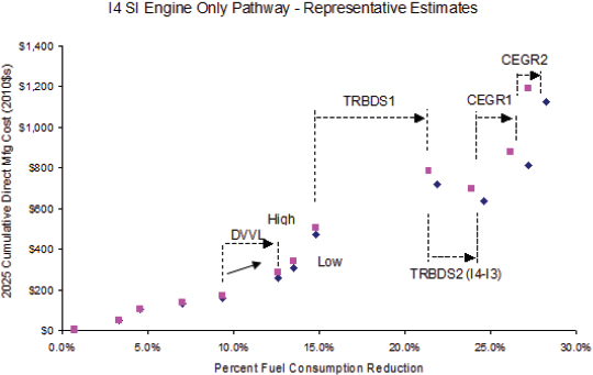
| Time Frame | Fuel Consumption Reduction (%) | 2025 MY Direct Manufacturing Cost (2010$) |
| Null vehicle to 2016 MY | 8.2 | 109 - 118 |
| 2017 MY to 2025 MY | 17.1 - 17.9 | 526 - 705 |
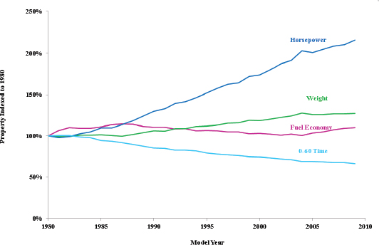
FIGURE 2.9 Changes in horsepower, 0 to 60 time, weight, and fuel economy, 1980 to 2009.
SOURCE: DOE (2010).
ratio was calculated to result in a 2.6 percent increase in fuel consumption. Consistent with this calculated result, Knittel (2011) estimated that reducing horsepower and torque by 1 percent increases fuel economy by roughly 0.3 percent, and a similar result was found by Michalek et al. (2004) in a study that used vehicle models to determine the effect of changes in engine power on fuel economy. Combining this result with the previous relationship indicates that a 10 percent decrease in 0 to 60 mph time will result in a 2.6 percent increase in fuel consumption. These results will vary depending on the initial value of 0 to 60 mph acceleration time and the weight of the vehicle, but the directional trend will remain.
In contrast to increasing performance, decreasing performance can provide significant reductions in fuel consumption. For a 3,500 lb vehicle, a 10 percent increase in 0 to 60 mph time from a typical average value of 8 seconds can result from approximately a 10 percent decrease in power/weight ratio. A 10 percent decrease in power-to-weight ratio was calculated from the NHTSA empirical expression to result in a 3.2 percent reduction in fuel consumption. In contrast to this method for reducing fuel consumption, a similar reduction in fuel consumption can be obtained by applying technologies that may have cost effectiveness values in the range of $25 to over $50 per percent reduction in fuel consumption.
The final CAFE rule states that the CAFE standards “should not . . . affect vehicles’ performance attributes” and the “technology cost and effectiveness estimates . . . reflect this constraint” (EPA/NHTSA 2012a). Although constant performance attributes were assumed in the technology effectiveness estimates, several manufacturers told the committee that vehicle performance would continue to be increased, as it was over the time period shown in Figure 2.10, due to competitive pressures.
SI Technologies and Off-Cycle Fuel Economy
There exists a gap between the fuel economy experienced on-road and that evaluated in the mandated test cycles. Deviation of real-world fuel economy from EPA window sticker value, as well as from the CAFE compliance values, is expected to increase as some additional SI fuel economy technologies are applied to vehicles. When a vehicle is driven more aggressively, such as at higher speeds and higher acceleration rates than specified by the FTP75 and the Highway Fuel Economy Test (HWFET) drive cycles used for CAFE compliance, more fuel is consumed. If the vehicle has a conventional, naturally aspirated engine, the fuel consumption outside the CAFE drive cycles differ from on-cycle fuel consumption due to the gradual changes in BSFC values on the fuel consumption map of the engine and the increased power requirements at higher speeds or accelerations rates.
For a turbocharged, downsized engine, changes in the BSFC values on the fuel consumption map outside the CAFE drive cycles can be greater than with a naturally aspirated engine. For example, with a highly turbocharged and downsized engine, higher speeds may require enrichment to limit exhaust temperature to protect the turbocharger and catalyst. This enrichment would result in a greater increase in fuel consumption than would be experienced with a naturally aspired engine. A similar effect would occur during higher acceleration rates. This growing gap is not unique to SI technologies and may increase with use of technologies optimized for the test cycles. The possibly growing discrepancy between compliance and on-road fuel economy is discussed further in Chapter 10.
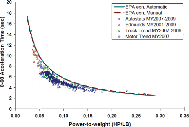
FIGURE 2.10 Performance as indicated by 0 to 60 mph acceleration time versus power-to-weight ratio.
SOURCE: Berry (2010). © 2010 Massachusetts Institute of Technology. Used with permission.
FUEL CONSUMPTION REDUCTION TECHNOLOGIES – NOT INCLUDED IN FINAL CAFE RULE ANALYSIS
This section discusses technologies reviewed but not included in the Agencies’ quantitative analysis, such as ethanol flex-fuel vehicles, vehicles fueled with compressed natural gas, lean burn engines, and homogeneous charge, compression ignition (HCCI) engines. The fuel consumption reductions for technologies using alternative fuels are shown in gasoline gallons equivalent (gge) in Table 2A.1 (Annex tables at the end of the chapter). Shown in parentheses after the gasoline gallons equivalent are the actual reductions in CAFE fuel economy resulting from the application of the utility factor in the case of flexible or bi-fuel vehicles and the petroleum equivalency factor (PEF) where applicable.
Ethanol Flexible Fuel Vehicles
Flexible-fuel vehicles (FFVs) allow more than one fuel to be used in a single tank. In the United States, these are ethanol FFVs that, in the case of LDVs, can be fueled with any mix of gasoline and ethanol from 0 percent to 85 percent ethanol. The primary technologies are a corrosion-resistant fuel system, including the fuel injectors, fuel lines, and fuel pump together with the control system for sensing and maintaining stoichiometry in the engine with the prevailing fuel mixture in the tank. The incremental direct manufacturing cost for an ethanol FFV is estimated to be $100 for a large car with a V6 engine, while the cost is lower for an I4 engine and higher for a V8 engine, since the incremental cost is partially dependent on the number of corrosion-resistant injectors (Woodall 2010).
For several manufacturers, FFVs account for a large percentage of total production, in part because FFVs generate credits toward CAFE compliance. In MY 2012, 17 percent of sales overall were FFVs, with some manufacturers at much higher percentages: GM’s sales were 44 percent FFVs, Chrysler’s, 35 percent, and Ford’s, 28 percent (EPA 2014c). An FFV achieves significantly lower miles per gallon operating on 85 percent ethanol (E85) than it does operating on gasoline, because the energy density (Btu/gal) of E85 is 27-37 percent lower than that of gasoline. On an energy-equivalent basis, however, an FFV’s ethanol and gasoline fuel economies are very similar. E85 supply is limited in most of the U.S., and NREL data indicate that less than 1 percent of the fuel used by the nation’s more than 11 million FFVs is ethanol (Graves 2014; Moriarty 2013).
Ethanol has an RON of 109, with an AKI of 99.5. Although this high octane rating has the potential to provide for an increase in fuel economy by increasing the compression ratio, such optimization for ethanol is not possible since the compression ratio of an FFV is limited by operation on gasoline, typically with an RON of 91.
For CAFE compliance purposes, the fuel economy of an FFV is measured on gasoline and on E85, the fuel economy on E85 is adjusted to reflect its petroleum content, and the gasoline and adjusted-E85 fuel economy values are weighed using a utility factor to reflect use of E85. As noted above, fuel economy on a per volume basis (mpg) is lower when operating on E85 than when operating on gasoline, typically about 68% of the gasoline mpg. The E85 fuel economy is adjusted by dividing by the Petroleum Equivalency Factor (PEF) of 0.15 to reflect that E85 is considered to consist of only 15 percent petroleum-derived fuel. An FFV is currently considered to use E85 for 50 percent of the time, resulting in a utilization factor of 0.5. This results in an overall certification fuel economy for an FFV calculated using the following equation:
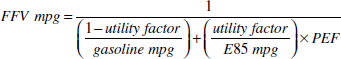
For an FFV with measured fuel economy of 25 mpg on gasoline and 17 mpg on E85, for example, this results in a certification fuel economy of 41 mpg, or 1.64 times the fuel economy on gasoline. This 64 percent increase under CAFE standards in certification fuel economy for FFVs illustrates why many manufacturers currently make FFVs a large percentage of their total production fleet. The 64 percent increase is equivalent to a 40 percent reduction in fuel consumption. However, there is a cap (1.2 mpg for 2014 MY cars and 2014 MY trucks, separately) on the amount a manufacturer may increase its fleet average fuel economy under the CAFE program using this calculation of fuel economy for FFVs. The cap will be phased out beginning in MY 2016 and will reach zero by 2020.
For MY 2017 and 2018, manufacturers will continue to calculate the CAFE fuel economy using a 50/50 harmonic average of the fuel economy for the alternative fuel and the conventional fuel. The fuel economy for the alternative fuel continues to be increased by dividing it by 0.15, the PEF. After 2019, the CAFE fuel economy will weight the FFV fuel economy of the two values using the same real-world weighting factor that is used under the EPA program. In contrast to the CAFE program, EPA is implementing changes to the GHG program after 2015; these changes include establishment of the E85 weighting factor and elimination of the 0.15 multiplier for E85 GHG emissions. Recently, EPA finalized an E85 weighting factor of 0.1410 for MY 2016-2018, which manufacturers may use for weighting CO2 emissions for purposes of FFV certification (EPA 2013a; EPA 2014d). EPA will take action to establish weighting factors for MY 2019 and beyond after a full review of updated information.
_____________
10 0.14 is the weighting of CO2 emissions for E85 fuel and 1 – 0.14 is the weighting of CO2 emissions for conventional fuel. Through 2015 MY, the weighting factors are 0.5 for CO2 emissions for E85 fuel multiplied by 0.15 and 1 – 0.5 for CO2 emissions for conventional fuel.
Although this weighting factor is not applicable to the CAFE program in this time frame, a common factor will apply after the 2019 MY. Upon transitioning to the real-world weighting factors, the CAFE and GHG programs will no longer cap the amount by which FFVs can raise manufacturers’ average fuel economy. The crediting of alternative fueled vehicles in the CAFE and GHG programs is discussed further in Chapter 10.
Compressed Natural Gas Vehicles
Natural gas has various properties that make it appealing as a vehicle fuel, including its abundance, relatively low cost at present in the United States, and high octane rating (120+ AKI compared to 87 AKI for regular gasoline) (AFDC n.d.). With regard to efficiency, however, commercialized compressed natural gas (CNG) vehicles have not demonstrated an advantage over gasoline vehicles. Table 2.32 compares key attributes of Honda’s Civic Natural Gas vehicle with a similar gasoline model. For the past several years, the Civic CNG vehicle has been the only OEM-dedicated natural gas vehicle in the light-duty market.
Since natural gas has a substantially higher octane rating than gasoline, allowing a higher compression ratio, this capability is applied to the Civic Natural Gas vehicle to partially offset the lower peak power of the engine, which comes from the displacement of air for combustion in the cylinders by natural gas. Other consumer considerations are the natural gas vehicle’s reduced range and trunk space, both due to the low energy density of CNG, and an incremental retail price of over $9,500 relative to the gasoline model. Annual sales have been less than 1,500 units, mostly to corporate and government fleets. The $9,500 incremental price of the Honda Civic CNG vehicle was used as the basis for estimating an incremental direct manufacturing cost of $6,000 for a CNG vehicle by using an ICM of 1.5. Since this cost is based on a very low production volume, reductions in this cost are expected if higher volumes were to develop.
The final CAFE rule provides an incentive for producing CNG vehicles. The CAFE fuel economy of a CNG vehicle is determined by dividing its fuel economy in equivalent miles per gallon of gasoline by the PEF of 0.15 (EPA/NHTSA 2012a). Therefore, a CNG vehicle with a combined CAFE fuel economy of 30 mpgge would have a 200 mpg CAFE fuel economy rating.
Although CNG has the potential to reduce operating costs and CO2 emissions, consumer acceptance issues, including lack of refueling stations, slow and noisy refueling process, fewer model choices, and perceived danger of CNG, must be successfully addressed. Several European manufacturers are currently marketing CNG vehicles in Europe and Asia, which could be brought to the United States if adequate infrastructure existed. Some interest was expressed by the natural gas industry and some automakers in extending the CNG multipliers beyond 2021.
Bi-fuel CNG/Gasoline Vehicles
Bi-fuel CNG/gasoline vehicles are equipped with a natural gas tank and a gasoline tank and can switch operation from one fuel to the other. Bi-fuel vehicles may attract more customer interest than dedicated CNG vehicles. Low natural gas prices generated considerable interest in natural gas for heavy-duty applications that has extended to bi-fuel versions of the 2013 Chevrolet Silverado, GMC Sierra, Ford Super Duty, and Ram heavy-duty pickups trucks and the Ford E Series van (autonet.ca 2013).
Ford recently announced that the 2014 MY F-150 light-duty pickup with the 3.7L V6 engine can be ordered with a “prep” option from the factory for natural gas, which can then be sent to an outfitter for conversion to CNG operation. The “prep” option includes hardened valves, valve seats, and pistons and piston rings and has a retail cost of $315 (Ford News Center 2013). The F-150 will be able to operate on either natural gas or gasoline through separate fuel systems. The CNG conversion, which includes fuel tanks, fuel lines, and unique fuel injectors, will cost $6,000 to $9,500 depend-
TABLE 2.32 Comparison of 2012 MY Gasoline and Natural Gas Honda Civic
| Gasoline | Natural Gas | ||||||||||||||||||
| Displacement | 1.8L | 1.8L | |||||||||||||||||
| Compression Ratio | 10.6:1 | 12.7:1 | |||||||||||||||||
| Power | 140 hp | 110 hp | |||||||||||||||||
| EPA Fuel Economy - MPG (City/Hwy/Combined) | 28 / 39 / 32 | 27 / 38 / 31a | |||||||||||||||||
| Fuel Capacity | 13.2 gal | 8.03 GGE a | (3600 psi CNG tank) | ||||||||||||||||
| Range (Using Combined MPG) | 422 miles | 249 miles | |||||||||||||||||
| Cargo Volume | 12.5 cu. ft. | 6.1 cu. ft. | |||||||||||||||||
| Retail Price | $17,545 | $27,095 | |||||||||||||||||
a GGE (Gasoline Gallons Equivalent).
SOURCE: Honda.com and Edmunds.com (2013).
ing on fuel tank capacity. General Motors announced that the 2015 MY Chevrolet Impala will include a powertrain that switches from compressed natural gas to gasoline, with a total driving range of up to 500 miles (Krasny 2013). Costs were not available at the time of the announcement.
These bi-fuel LDVs can switch operation from one fuel to the other, which minimizes the range anxiety resulting from the dearth of CNG refueling stations. This flexibility comes at the cost of having a sub-optimal engine design and combustion as well as two separate tanks and fuel lines for both the gasoline and the natural gas.
In the CAFE program for MYs 2017–2019, the fuel economy of dual fuel vehicles will be determined in the same manner as specified in the MY 2012–2016 rule. Beginning in MY 2020, in order to use the utility factor based on estimated usage of CNG, dual fuel CNG vehicles must have a minimum CNG range-to-gasoline range ratio of 2.0, and gasoline can only be used when the CNG tank is empty. Any dual fuel CNG vehicle that does not meet this requirement would use a utility factor of 0.50, the value that has been used in the past for dual fuel vehicles under the CAFE program. For a dual fuel CNG vehicle with a fuel economy of 25 mpg using gasoline and 95 percent of the gasoline fuel economy on a mpgge basis using natural gas, the overall CAFE fuel economy would be 43.2 mpg (1/mpg = 0.5/25 + 0.5/(0.95 × 25)/0.15), or 1.73 times the fuel economy on gasoline, which is equivalent to a 42 percent reduction in fuel consumption. EPA provides multipliers for both dedicated and dual fuel CNG vehicles for MYs 2017-2021 that are equivalent to the multipliers for PHEVs.
Lean Burn Gasoline Direct Injection
Lean burn, spray-guided fuel injection systems operating at higher injection pressures than conventional direct injection engines have a potential for a 5 to 15 percent reduction in fuel consumption, resulting in a thermal efficiency approaching that of a diesel engine (NHTSA 2009). NHTSA has stated that when combined with advanced NOx aftertreatment systems, lean-burn GDI engines may be a possibility in North America.
Tier 3 ultra low sulfur gasoline (less than 15 ppm S) may stimulate renewed interest in lean-burn GDI engines. NOx aftertreatment systems for lean burn engines consist of lean NOx traps (LNTs), which preferentially store sulfate compounds from the fuel, thereby reducing NOx storage capacity over time. As a consequence, the system must undergo periodic desulfurization by operating at a net-fuel-rich condition at high temperatures in order to retain NOx trapping efficiency (EPA/NHTSA 2012b). Previous experience in Europe with production lean burn engines indicated that they did not provide the expected reductions in fuel consumption, partially due to frequent desulfurization of the lean NOx trap that required periodic rich operation of the engine. The reduction in sulfur content may permit the use of a lean NOx trap (LNT) without requiring frequent desulfurization, though at high cost (MARTEC 2010).
EPA Tier 3 motor vehicle emission and fuel standards (EPA 2014b) will reduce gasoline sulfur content to 10 ppm on an annual average basis, starting on January 1, 2017. This level is similar to levels already being achieved in California, Europe and Japan. EPA will continue to cap sulfur levels at 80 ppm and 95 ppm at the refinery gate and at the pump, respectively. Concerns remain with this requirement for the elevated sulfur levels at the retail pump, with the cap remaining at 95 ppm. Whether an average fuel sulfur requirement, rather than a sulfur cap on all fuel, would be sufficient to accommodate a technology such as lean burn in the real world remains a subject of discussion. Several vehicle manufacturers provided comments to EPA that lean burn engines may require 20 ppm and 25 ppm limits at the refinery gate and downstream, respectively, which are significantly lower than the limits specified by EPA.
Only a few vehicle manufacturers mentioned consideration of lean burn engines in their future CAFE compliance plans. Mercedes claims that lean burn can provide a 7 percent reduction in fuel consumption. In 2014, Mercedes had lean burn in seven of their vehicles in Europe, although uncertainty remains regarding whether the Tier 3 fuel requirements for fuel sulfur content are low enough for lean burn technologies to be introduced into the United States. The committee estimated an $800 direct manufacturing cost for a lean burn system for an I4 engine by accounting for a lean NOx trap, direct injection, and an ignition system upgrade for the dilute combustion.
Electric Assist Turbocharging
An electric motor can be added to assist a turbocharger at low engine speeds to mitigate unwanted performance characteristics such as turbocharger lag and low boost pressure. Connecting a motor to the turbocharger shaft can provide the extra boost needed to overcome the torque deficit at low engine speeds (Uchida 2006). Both electric turbochargers and superchargers are being developed. Honeywell, Valeo, and BorgWarner have been reported to be developing electrically assisted turbochargers.
BMW has been reported to be working on a hybrid turbocharger, in which the compressor and turbine can be coupled to an electric motor-generator with clutches. The turbine and compressor rotate on different shafts, and clutches can be used to couple them to the motor-generator. Between the turbine and compressor is an electric motor. In full throttle acceleration, the compressor is driven by the motor. In this process, the time that would have been required for exhaust gases to spin up a traditional turbine to its operating speed is almost eliminated. When the turbine has reached its operating speed, a clutch couples it to the motor-generator. At this condition, the electric motor-generator functions in the generator mode. The resultant current flows to the battery,
| Test Results for Vehicle with Eaton EAVS Supercharger System | |||||||||||||||||||
| FTP-75 (mpg) | HWY (mpg) | Combined (mpg) | Fuel consumption (gal/100 mi) | ||||||||||||||||
| 2.8L Naturally Aspirated Engine | 22.00 | 35.60 | 26.57 | 3.764 | |||||||||||||||
| 1.4L with Eaton EAVS Supercharger | 30.44 | 52.04 | 37.43 | 2.672 | |||||||||||||||
| Fuel Consumption Reduction = | 29% | ||||||||||||||||||
| Comparison of Fuel Consumption Reductions Using NHTSA Estimates for Each Function/Technology | |||||||||||||||||||
| Functions | Eaton EAVS-SC (% FC reduction) | Turbocharged Downsized Engine with Added Technologie s (% FC Reduction) | |||||||||||||||||
| 50% downsizing | 20.1 | 20.1 | |||||||||||||||||
| Stop-start | 2.1 | 2.1 | |||||||||||||||||
| Mild Hybrid (Reduced effectiveness for EAVS-SC) | 2.2 | 6.55 | |||||||||||||||||
| Improved Accessories 1 | 1.22 | 1.22 | |||||||||||||||||
| Improved Accessories 2 | 2.36 | 2.36 | |||||||||||||||||
| Multiplicative Total = | 26% | 29% | |||||||||||||||||
and the surplus load from the generator is used to control the turbine’s speed (Spinelli 2011).
A variation of the electrically assisted turbocharger is BorgWarner Turbo Systems’ eBooster. This system employs an electric motor to drive a compressor and may be positioned either ahead of or behind the turbocharger. Unlike conventional electrically assisted turbochargers, the eBooster concept has two stages, similar to a series of two turbo-machines. As a result, the two units’ pressure ratios are multiplied. This system is currently under development in close cooperation with various customers (BorgWarner n.d.). Audi has been reported to be working on a similar system called an “electric biturbo.” This system employs an electric compressor to rapidly provide a low-rpm performance improvement. It is combined with a traditional turbocharger, which is used to achieve greater power at the top end. Volvo recently announced a triple-boost engine with two parallel turbochargers linked to an electrically powered compressor to eliminate the lag in boost pressure at the lower engine speeds (Birch 2014).
Another variation is Eaton’s Electrically Assisted Variable Speed (EAVS) supercharger, which includes the following additional features: stop-start, mild hybrid, and improved accessories (Tsourapas et al. 2014). The system combines a variable speed supercharger with engine stop-start functions together with regenerative (mild hybrid) capabilities using a planetary gear set to couple the engine, supercharger and motor. The supercharger is combined with a small electric motor having approximately one-third the power of traditional mild hybrids and a battery to provide engine boost at any speed without lag. Eaton reported that a 50 percent downsized engine with the EAVS supercharger system provided a 29 percent reduction in fuel consumption, as shown in Table 2.33. Also shown in Table 2.33 is a comparison of the fuel consumption reduction that could be achieved by combining the features in the Eaton vehicle by using NHTSA’s estimates for each technology. This analysis yielded a 26 percent reduction in fuel consumption, which was in the range of Eaton’s measured data from its experimental test vehicle. In September 2014, DOE awarded a $1.75M cost-sharing project to Eaton to demonstrate an electrically assisted supercharger operating with the energy from a waste heat recovery system.
The committee’s estimated incremental direct manufacturing costs for the EAVS supercharger system when applied to a midsize car with an I4 engine was approximately $1,300 and when applied to a large car with a V6 engine was approximately $1,000, as shown in Table 2.34. These estimated costs are within the range estimated by using NHTSA’s costs for a turbocharged, downsized engine together with the costs for the additional functions provided by the EAVS supercharger system listed in Table 2.33. Applying the EAVS supercharger system to a V6 engine results in a lower cost than applying it to an I4 engine because of the larger savings in downsizing the V6 engine to an I4 engine as compared to downsizing an I4 engine to an I3 engine.
HCCI for Gasoline Fueled Engines
Concept of Operation and Expected Benefits
In homogeneous charge, compression ignition (HCCI) engines, also known as low-temperature combustion engines, a premixed charge of fuel and air is compressed until
TABLE 2.34 Estimated Direct Manufacturing Cost for the Eaton EAVS Supercharger System
| EAVS Supercharger with 50% SI Engine Downsizing | |||||||||||||||||||
| EAVS SC - I4 to I3 Midsize Car | EAVS SC - V6 to I4 Large Car | ||||||||||||||||||
| Components | 2020 MY NRC Estimate | Components | 2020 MY NRC Estimate | Comments | |||||||||||||||
| I4 to I3 | V6 to I4 | ||||||||||||||||||
| IC Engine Size | 2.4L to 1.2L | 2.8L to 1.4L | |||||||||||||||||
| EAVS SC | $1,050 | EAVS SC | $1,050 | Expert estimate | |||||||||||||||
| Battery | $505 | Battery | $505 | NHTSA RIA p. 330 | |||||||||||||||
| System Cost to OEM | Total = | $1,555 | Total = | $1,555 | |||||||||||||||
| Downsizing I4 - I3 | -$161 | Downsizing V6 - I4 | -$465 | TSD Table 3-32 | |||||||||||||||
| Alternatora | -$52 | Alternatora | -$52 | ||||||||||||||||
| 12 V Batterya | -$15 | 12 V Batterya | -$15 | ||||||||||||||||
| Starter motora | -$26 | Starter motora | -$26 | ||||||||||||||||
| Cost Reductions | Total = | -$254 | Total = | -$558 | |||||||||||||||
| Vehicle Net Impact | $1,302 | $998 | |||||||||||||||||
| Service partsa | Retail Price ($) | Estimated Direct Mfg Cost ($) | |||||||||||||||||
| Alternator | 348 | 52 | |||||||||||||||||
| Battery | 100 | 15 | |||||||||||||||||
| Starter motor | 170 | 26 | |||||||||||||||||
a DMC~15% of retail price.
it auto-ignites, with heat release occurring throughout the cylinder volume rather than in a flame front (Najt and Foster 1983; Thring 1989). This combustion concept is particularly challenging at high loads since the high levels of dilution necessary to limit the pressure rise rate to ensure acceptable NVH levels may not be achievable. At lighter loads, the dilution, which increases thermodynamic efficiency and lowers pumping losses and peak combustion temperatures, results in reduced fuel consumption, NOx and particulate emissions. As a result, the HCCI engine created high expectations for overcoming some of the disadvantages of the SI engine and the compression ignition (CI) engine and has, for many years, attracted significant interest and research investment (Epping et al. 2002; Kulzer et al. 2006).
The factors that contribute to the improved efficiency of an HCCI engine include the following:
- Higher compression ratio than conventional SI engines;
- Lean or dilute operation with air and/or residuals providing a higher specific heat ratio for improved thermodynamic efficiency;
- Low temperatures and rapid heat release that reduce heat losses; and
- Low pumping losses due to dilute operation relative to a throttled SI engine.
Progress to Date
Many challenges in applying the HCCI concept to light-duty vehicles continue to be addressed in a range of research programs. Control of auto-ignition phasing has been achieved with a variety of methods that affect the thermodynamic state and the chemical composition of the charge. VVT to control HCCI combustion phasing with high amounts of residuals, sometimes called controlled auto ignition (CAI), appears to be the most promising method. CAI relies on increasing cylinder residuals with exhaust valve re-breathing or a negative valve overlap (NVO) time period during which the intake and exhaust valves are closed for the first part of each piston’s intake stroke, creating a high vacuum in the associated cylinder. As the intake valve opens, the high pressure differential elevates turbulent mixing intensity, which contributes to a leaner air/fuel ratio and reduced exhaust-gas emissions (Willand et al. 1998; Filipe and Stein 2002).
To achieve unthrottled operation with high residuals, HCCI engines generally rely on low valve lifts at low loads. Consequently, a VVL mechanism with at least two lift settings is expected to be necessary for high load operation and transition to SI operation. Internal dilution can be controlled with the NVO strategy, since it offers fast cycle-to-cycle control of the initial cylinder conditions necessary to achieve autoignition. Successful HCCI operation relies on combustion feedback, so in-cylinder pressure sensing in
every cylinder is expected to be necessary. The speed range of HCCI is also limited due to the chemically driven combustion process, which includes a delay prior to initiation. At high loads the heat release becomes increasingly violent and eventually could lead to damaging knock or even thermal run away (Chiang et al. 2007a; Olsson et al. 2002; Thring 1989). At high loads, the combustion phasing must be retarded to avoid knocking. Late phasing, however, involves incomplete combustion, where unburned fuel from one cycle adds to the injected fuel of the next cycle, causing significant cycle-to-cycle variability (Thring 1989; Koopmans 2001; Hellstrom 2012). Although start of injection (SOI) control based on combustion feedback was shown to reduce this cyclic variability, the overall fuel consumption and NOx emissions began to deteriorate (Gerdes 2012; Hellstrom 2012).
As a result of these issues, a gasoline engine must return to the SI mode at high loads (Kulzer et al. 2007). In 2009 General Motors demonstrated a vehicle with HCCI operation from idle to speeds up to 60 mph by using multiple injections and multiple ignitions (Green Car Congress 2009b; Yun et al. 2009). Combustion-induced noise was identified as an issue that needed to be resolved. No drive cycle emissions or fuel consumption results have been reported from this project.
Current Projects
Current efforts focus on (1) managing the HCCI-SI combustion mode switches for covering the entire speed-load range and (2) extending the gasoline HCCI range to avoid the need for mode switches. Due to the limited load range for successful HCCI operation, recently shown to be below 3 bar BMEP, mode switching from HCCI combustion to conventional SI combustion and back is required for covering the full speed and load range of an engine (Nuesch 2014).
The mode switch control problem is difficult due to the different nature of each combustion mode (Koopmans 2001). Switching into the HCCI mode is particularly demanding, with only indirect control of the combustion. The modes operate under significantly different conditions, with HCCI often operating unthrottled and lean while the SI mode is throttled and stoichiometric (Cairns and Blaxill 2005a, 2005b; Nier et al. 2012). Because of the dynamics in the air path, the transitions require several engine cycles, during which neither mode operates under normal conditions, and they incur fuel penalties. The combustion is generally less efficient during the transitions than in either stabilized mode.
Another issue for HCCI engines is the coordination of the engine modes with the exhaust aftertreatment system. Although reduction catalysts may not be necessary with the low NOx emissions in the lean HCCI mode, the three-way catalyst (TWC) needs to be fully warmed up and ready to convert engine-out emissions when the engine switches to the SI mode. HCCI has low exhaust temperatures and might not maintain the catalyst light-off temperature after prolonged operation (Nier and Karrelmeyer 2011). Moreover, during an HCCI to SI mode switch, the engine might need to run rich to deplete the TWC oxygen storage to expedite the NOx conversion in the SI mode. During these rich periods the fuel penalty of mode switching increases and can be detrimental to the overall fuel economy. The ACCESS project, discussed later in this section, found that maintaining tailpipe emissions levels equivalent to those of a super ultra-low emission vehicle during mode switching eliminated the fuel consumption benefits of HCCI.
Mode switching could be avoided if the load range for HCCI combustion mode could be extended to the full operating range of the engine. Investigations of the combination of ignition, multiple injections, positive valve overlap (PVO), and boosting or supercharging are under way for extending HCCI operation, and these investigations are discussed in Appendix M. Some of the projects that are investigating HCCI-SI mode switching and extending the gasoline HCCI load range are summarized below, with additional details provided in Appendix M.
Advanced Combustion Control Enabling Systems and Solutions (ACCESS) (AVL, Bosch, Emitech, Stanford, University of Michigan)
The Advanced Combustion, Controls, Enabling Systems and Solutions (ACCESS) project, partially funded by a DOE grant, is focused on coordinating multi-mode combustion events over the engine drive cycle operating conditions. The project goal is to improve fuel economy by 25 percent by implementing part-load HCCI operation in a turbocharged, downsized engine meeting the California tailpipe emission standards for super ultra-low emission vehicles (SULEVs). A turbocharged, downsized 2.0L I4 engine is being used to replace the naturally aspirated 3.6L V6 engine. A 5 percent fuel economy improvement relative to a turbocharged, downsized engine was projected for the HCCI combustion mode on the FTP75 cycle, based on multicylinder engine data. However, this potential fuel consumption benefit of lean HCCI was eliminated under the SULEV emission constraints due to the need to switch to a fuel-rich mode after lean operation to deplete the oxygen storage and restore the three-way catalyst (TWC) NOx conversion efficiency. Stoichiometric HCCI and spark-assisted HCCI (SACI) are now the emphasis of this project, with a vehicle demonstration planned at the end of the DOE contract in December 2014.
The committee estimated that HCCI, applied to an I4 engine, would have an incremental direct manufacturing cost of $450. This estimate includes the costs for a cooled EGR system, four combustion pressure sensors, and an electronic control system with appropriate signal processing, and input/output capabilities, together with the necessary wiring and connectors.
Homogeneous Charge Compression Ignition (HCCI) (ORNL and Delphi HCCI)
Oak Ridge National Laboratory (ORNL) and Delphi are investigating ways to expand the load where gasoline HCCI can be achieved (Szybist et al. 2012, 2013) on a single-cylinder version of a 2.0L four-cylinder engine with the compression ratio increased to 11.85:1. Recent results have shown that the load for HCCI operation in a naturally aspirated engine can be increased from 3.5 bar IMEP to 6.5 bar IMEP, with high levels of boost pressure up to 1.9 bar to provide additional air dilution as well as with the use of external EGR. Under boosted conditions, NOx emissions remained low (<0.01 g/kWh).11
Gasoline Direct Injection Compression Ignition (GDICI) (University of Wisconsin and General Motors)
The University of Wisconsin and General Motors have investigated the use of 87 AKI regular-grade gasoline in a high-speed, direct-injection, light-duty compression ignition engine to extend the low-temperature combustion (LTC) regime to high loads (Ra et al. 2011). This system is called gasoline direct injection compression ignition (GDICI). The investigation found that GDICI operation of a light-duty engine was feasible under full load conditions of 16 bar indicated mean effective pressure (IMEP), thereby significantly extending the low-emission combustion concept (Ra et al. 2012). The engine had a compression ratio of approximately 16.5:1 and operated with multiple injections, specifically double- and triple-pulse injections. Both particulate matter (PM) and NOx emissions were reduced to levels of about 0.1 g/kg-f while achieving an indicated specific fuel consumption (ISFC) as low as 173 g/kW-hr with a triple pulse fuel injection strategy (Ra et al. 2012).
Gasoline Direct Injection Compression Ignition (GDCI) (Delphi, Hyundai, Wayne State University, University of Wisconsin, Wisconsin Engine Research Center)
Similar to the University of Wisconsin and General Motors GDICI engine, Delphi and Hyundai are developing, under a DOE contract, a Gasoline Direct Injection Compression Ignition (GDCI) engine with the goal of achieving full-time, low-temperature combustion using multiple late injections over the entire engine speed-load map from idle to full load (Sellnau et al. 2012). Complete mixing of all the fuel in a homogeneous charge is averted with late injections, as this would cause rapid burning of the whole mixture. Regular unleaded gasoline (90.6 RON) and unleaded gasoline with 10 percent ethanol (91.7 RON) fuels are being used in this engine. Compression ratios between 14:1 and 16.2:1 were evaluated. Low-temperature combustion was demonstrated from 2 to 18 bar IMEP by maintaining 40 percent EGR at high loads and using inlet air heating at low loads (Confer et al. 2012). A minimum ISFC of 181 g/kW-hr was obtained with NOx emissions less than 0.2 g/kW-hr, although this NOx level would exceed the 2025 Tier 3 standards for a midsized car (see footnote 11). A multi-cylinder engine with the GDCI combustion system has been built, and testing was under way as of May 2013 (Confer et al. 2013). Demonstration of this engine in a vehicle, including cold starting and transient operation, was scheduled to be completed by the end of the DOE contract in 2014. In September 2014, DOE awarded a $10 million cost-sharing project to Delphi to accelerate the development of the GDCI low-temperature combustion technology. The committee estimated that the GDCI engine could have an incremental direct manufacturing cost approximately equal to that of an advanced diesel engine, which is estimated in Chapter 3 at $2,572 (2010 dollars) in 2025 for a midsize car relative to a baseline engine.
HCCI Engines Using Other Fuels
The previous section focused on the application of HCCI combustion to gasoline-fueled engines. However, research is under way to apply HCCI combustion across the spectrum of fuels and fuel injection processes. This spectrum of HCCI combustion research is depicted graphically in Figure 2.11. In addition to gasoline at one end of the spectrum and diesel fuel at the other end, multiple fuels in combination with port-injection and direct-injection scenarios with a mixture of low- and high-reactivity fuels are also being investigated within this spectrum. Alternative and low-carbon fuels are also considered within this spectrum. The combustion technologies for improving the classical diesel engine shown on the right-hand side of Figure 2.11 are discussed in Chapter 3.
The committee has made the following assessments of HCCI for gasoline-fueled engines:
- HCCI has been projected to provide up to 5 percent reduction in fuel consumption relative to a turbocharged, downsized engine.
- Maintaining SULEV (equivalent to Tier 3 or Tier 2 Bin 2) emissions during mode switching between lean HCCI and stoichiometric SI combustion modes can eliminate the HCCI fuel consumption reduction benefit if a TWC is used.
- Lean HCCI with its currently limited operating range requiring mode switching to SI combustion with TWC aftertreatment alone is not a suitable low-emission,
_____________
11 NOx emissions reported in g/kg-f and g/kW-h can be approximately related to each other and to the standard in g/mi as follows (using on-road energy from Table 3-62, TSD, for a 3500 lb midsize car):
(NOx g/kg-f) × (ISFC g-f/kW-hr)/(1,000 g/kg) = NOx g/kW-hr
(0.1 g/kg-f) × (180 g-f/kW-hr)/1,000 =0.018 g/kW-hr
(NOx g/kW-hr) × (.277 kW-hr/mi) = NOx g/mi
(0.018 g/kW-hr × (.277 kW-hr/mi) = 0.005 g/mi
Reference: Tier 3 Standard: 0.030 g/mi NMOG + NOx (EPA 2014b) (approximately 0.020 g/mi for NOx).
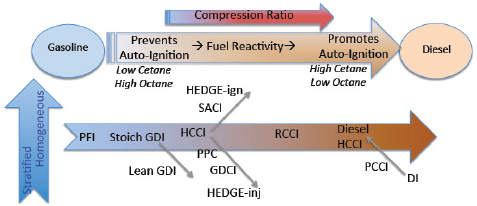
FIGURE 2.11 Advanced combustion concept spanning the range from gasoline SI to diesel CI engines. NOTE: SI, spark ignition; GCI, gasoline compression ignition; RCCI, reactivity controlled compression ignition (dual-fuel); and CDC, conventional diesel combustion.
SOURCE: Daw (2013). Oak Ridge National Laboratory.
-
high-efficiency concept. Lean exhaust aftertreatment may be required to realize efficiency improvements.
- Further research and development is needed in advanced turbocharging and multiple-lift valvetrains for maintaining high dilution and low pumping losses to support widening the LTC combustion range.
- The benefits of HCCI relative to conventional engines might not be substantial as new technologies, including EGR dilution and unthrottled operation facilitated by VVL, are added to conventional combustion engines.
The committee forecasts that, although HCCI is not likely to have an impact on CAFE by the 2025 MY since the technology is still in the laboratory, it might have a role by the 2030 timeframe if the potential fuel consumption benefits can be demonstrated at Tier 3 emission standards.
FUEL CONSUMPTION REDUCTION TECHNOLOGIES – NOT CONSIDERED IN FINAL CAFE RULE ANALYSIS
In contrast to the previous section, which discusses technologies reviewed but not included in the Agencies’ quantitative analysis, this section discusses fuel economy technologies not considered at all in the Agencies’ analysis, including high compression ratio engines, ethanol-boosted engines, dedicated EGR technologies, variable compression ratio and displacement engines, camless valvetrains, and waste heat recovery.
High Compression Ratio with High Octane Gasoline
Fuel Consumption Reduction Potential
Increasing the octane rating of gasoline raises resistance to knock and therefore allows higher compression ratios in the engine. Higher compression ratios, in turn, can lead to higher brake thermal efficiency, although the incremental improvement in efficiency diminishes as the compression ratio increases. The effects of compression ratio on brake thermal efficiency, together with ITE and mechanical efficiency, are shown in Figures 2.12a for full load conditions and Figure 2.12b for part load conditions. The derivation of these figures is described in Appendix N. These figures illustrate the following effects of compression ratio on brake thermal efficiency:
- At full load, brake thermal efficiency increases, but at a decreasing rate, with increasing compression ratio, similar to ITE.
- At part load, up to 3 percent reduction in fuel consumption for naturally aspirated engines might be realized if compression ratio is increased from today’s typical level of 10:1 to approximately 12:1, which is approximately a 1.5 percent reduction in fuel consumption per 1.0 compression ratio increase. Possibly greater reductions in fuel consumption might be realized for turbocharged engines capable of operating at higher boost pressures without knock so that further downsizing could be realized. Increasing gasoline octane from 91 RON of regular grade gasoline to 95 RON has been estimated to facilitate operation at a 12:1 compression ratio.
- At part load, nearly insignificant improvements in brake thermal efficiency on the CAFE test cycles are expected to be obtained by increasing compression ratio beyond approximately 12:1 due to the increasingly lower mechanical efficiency.
Current production vehicles use a range of compression ratios. The EPA Fuel Economy Guide (EPA 2012b) identifies vehicles that specify the use of premium gasoline. The Wards-MAHLE Engine Specification Chart was used to provide the compression ratio for the vehicles listed by EPA. Analyzing this information for 2012 MY intermediate
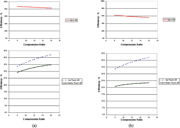
FIGURE 2.12 Effects of compression ratio on brake thermal efficiency, indicated thermal efficiency, and mechanical efficiency for (a) full load and (b) part load conditions representative of CAFE test cycles.
SOURCE: Developed from data in Heywood (1988).
and large cars (excluding turbocharged and direct injected engines) provided the following results:
| Compression Ratio | |
| Gasoline AKI Rating | (Avg +/- Std Dev) |
| Regular gasoline (87 AKI) | 10.3 +/- 0.2 |
| Premium gasoline (91 AKI) | 10.7 +/- 0.9 |
These results indicate that specifying premium gasoline facilitated an average 0.4 compression ratio increase, but the reasons why the full potential of a 1.0 to 2.0 compression ratio increase was not realized with the 4 AKI increase with premium gasoline in these comparisons are not known (Chow 2013).
Significant increases in compression ratio to approximately 11.5:1 have appeared in recent production vehicles while regular grade AKI 87 gasoline is still specified. This increase of approximately two compression ratios is projected to provide approximately a 3 percent reduction in fuel consumption. The control of knock at full load may be problematic; spark retard and cooling the mixture through enrichment are the usual methods for controlling knock at these conditions. These methods, however, will result in greater deterioration of customer fuel economy at high load conditions beyond the EPA test cycle. The committee estimated an incremental direct manufacturing cost for an increase in compression ratio would be approximately $50 for strengthened pistons and reduced tolerances to maintain the higher nominal compression ratio.
Fuel Octane Issues
Two octane numbers are associated with a fuel: a research octane number (RON), which is determined with a Cooperative Fuels Research (CFR) test engine running at a low speed of 600 rpm to represent engines at part throttle conditions, and a motor octane number (MON), which is determined with the CFR test engine running at a higher
speed of 900 rpm to represent severe high-load and high-throttle conditions. The octane rating for gasoline posted on pumps in the United States is the “anti-knock index,” which is the average of the RON and MON.
Gasolines commonly available in the United States have the following ratings:
| Grade | MON | RON | AKI | ||||||||||||||||
| Regular | 83 | 91 | 87 | ||||||||||||||||
| Premium | 87 | 95 | 91 | ||||||||||||||||
The heads of powertrain engineering for Chrysler, Ford and GM recently expressed support for an increase in octane for regular fuel from 91 RON to 95 RON, citing fuel efficiency benefits of 2-5 percent (Winter 2014). A recent MIT analytical study found that adopting 98 RON fuel as the new standard grade fuel could provide a 3 to 4.5 percent reduction in fuel consumption for naturally aspirated engines and a 3 to 7.3 percent reduction in fuel consumption for turbocharged engines (Chow et al. 2014). An alternative to refining high-octane gasoline is to increase octane through blending with higher octane components such as ethanol, which has an octane rating of about 113 (RFA 2013). To increase the use of biofuels in the United States, the EPA has issued waivers that allow gasoline to be sold with ethanol levels up to 15 percent by volume (increased from the previous limit of 10 percent) for MY 2001 and later vehicles (EPA 2011). A 15 percent ethanol blend could increase octane rating by 2-4 RON relative to current E10 regular grade gasoline (API 2010). With a higher minimum octane level, fuel consumption could be reduced by up to 5 percent, and the incremental direct manufacturing cost would be approximately $75 for an I4 engine resulting from strengthened pistons and reduced tolerances to maintain the nominal compression ratio.
Gasoline used in the United States today contains 10 percent ethanol on average (EIA 2013). Despite ethanol’s high octane content, the E10 currently sold in the U.S. has a 91 RON (AKI 87), which is the same as regular unleaded gasoline (E0). This has resulted from the petroleum industry’s reduction of the octane level in the gasoline blend stock used for E10. A vehicle manufacturer has suggested that, if the octane of the current gasoline blend stock were to be retained at current levels by refiners, the increased ethanol content may provide the necessary increase in octane level to 95 RON to facilitate higher compression ratio engines. Regular grade gasoline with a higher minimum octane level would need to be widely available before manufacturers might broadly offer engines with significantly increased compression ratios. EPA’s Tier 3 program, which changes the certification test fuel to E10 with octane representative of today’s level of 91 RON (87 AKI), does not contemplate the above scenario.
If a manufacturer were to design vehicles requiring higher octane fuel, such as E30 (30 percent ethanol by volume blend with gasoline), EPA’s Tier 3 program would allow manufacturers to petition the EPA Administrator for approval of the use of a higher octane fuel (EPA 2014d). If a petition is pursued, the manufacturer must demonstrate that the operator would use such a fuel. EPA stated that “this could help manufacturers that wish to raise compression ratio to improve vehicle efficiency, as a step toward complying with the 2017 and later light-duty CAFE standards” (EPA 2014d). Due to the relatively low energy content of ethanol, a vehicle tested on E30 would experience a loss in volumetric fuel economy. For CAFE compliance, EPA protocols call for an adjustment to the certification fuel economy based on the certification fuel energy content (see Tier 3 discussion in the section “Future Emission Standards for Criteria Pollutant Emissions”).
It should be noted that raising octane levels in gasoline would have impacts on the amount of energy used to produce the fuel and thus on the well-to-wheels GHG emissions. Raising octane rating through the refining process may involve the use of petroleum products more refined than gasoline, which increases the energy requirements. This raises the concern that the fuel efficiency benefits of using high-octane gasoline could be offset by an increase in full-fuel cycle greenhouse gas emissions (Green Car Congress 2013c). Work of the Japan Clean Air Program showed that increasing RON from 90 to 95 increased well-to-wheels GHG by about 1.5 percent (Szybist 2013). Where ethanol is used to increase octane, its source will determine well-to-wheels GHG emissions relative to gasoline. This remains a controversial topic.
High Compression Ratio, Exhaust Scavenging and Direct Injection
Several manufacturers are developing or producing engines with exceptionally high compression ratios while operating on regular grade (87 AKI) gasoline. The technologies being applied to these engines are described in this section.
Mazda Skyactiv Engine
Mazda has developed the Skyactiv technology, which it first introduced in the 2012 Mazda3. The 2.0L 155-hp four-cylinder Skyactiv engine in the Mazda3 was reported to consume 15 percent less fuel than its predecessor of the same displacement. Other improvements include 15 percent more torque, especially in the low-to-mid rpm range, a 10 percent weight reduction, and 30 percent less internal friction. The 12:1 compression ratio for this engine, which was increased to 13:1 in subsequent applications, uses 87 AKI octane regular gasoline in the United States. The key technologies applied in the Skyactiv engine include a high compression ratio, exhaust scavenging, and direct injection. A 4 into 2 into 1 exhaust manifold, dual variable valve timing, and direct
multi-hole gasoline injection are used to prevent preignition and knock at the high compression ratios. Additional technologies include a new design of pistons, shorter combustion duration, and delayed ignition during start-up. A fundamental characteristic of the engine is its higher compression ratio, which improves brake thermal efficiency.
Several enablers led to the use of high compression ratios. Dual VVT allows the use of more aggressive cam timing profiles to fully purge hot exhaust gases from the cylinders. The 4 into 2 into 1 exhaust manifold allows the exhaust gas to be expelled from each cylinder without interference from a pressure pulse from another cylinder. A disadvantage is that the long exhaust manifold moves the catalyst farther away, making rapid light-off to reduce emissions during start-up difficult. Direct injection with fine fuel atomization provides evaporative cooling in the combustion chamber to further facilitate operation at the high compression ratio.
The fuel consumption reductions achieved by the Mazda Skyactiv technology were examined based on the EPA fuel economy data shown in Table 2.35. The compact Mazda3 with Skyactiv technology provides a 9-10 percent reduction in fuel consumption relative to the Ford Focus with a 2.0L naturally aspirated engine and the Toyota Corolla with a 1.8L naturally aspirated engine. The midsize Mazda6 with Skyactiv technology provides a 12-14 percent reduction in fuel consumption relative to the Hyundai Sonata with a naturally aspirated engine or the Ford Fusion with a turbocharged, downsized engine. Figure 2.12 shows that an increase in compression ratio from 9:1 to 13:1 can increase brake thermal efficiency at moderate loads by 7 percent, which appears to account for a significant portion of the reduction in fuel consumption shown in Table 2.35. The committee obtained an independent estimate of 10 percent reduction in fuel consumption for Skyactiv technology (Duleep 2014). The cost of the Mazda Skyactive engine is not known, but is expected to be considerably lower than the cost for a downsized, turbocharged engine. An independent cost estimate in the range of $250 was obtained for the current Skyactiv engine (Duleep 2014).
Recently, Mazda announced plans for its next generation Skyactiv2 engine, which was claimed to be 30 percent more efficient than the current Skyactiv engine by using a compression ratio of 18:1 and lean HCCI combustion. However, these two features alone are estimated to provide less than a 10 percent reduction in fuel consumption. No test results are available to confirm the feasibility or benefits of Mazda’s announced features of the Skyactiv2 engine (Griemel 2014). The future path for the Skyactive approach beyond the present status is not clear, since the compatibility of turbocharging and downsizing with the exhaust scavenging system of the Skyactiv approach is unknown.
Atkinson Cycle Engines (for Non-Hybrid Vehicles)
Atkinson cycle engines have been used by Toyota in its hybrid vehicles since 1997. The Atkinson cycle engine with a high compression ratio enhances thermal efficiency but reduces torque. The Atkinson thermodynamic cycle is shown on a P-V diagram in Appendix D. In hybrid applications, the motor torque compensates for this reduction in engine torque. Hybrid applications of Atkinson cycle engines are discussed further in Chapter 4. Recently, Toyota announced that the issue with low torque has been overcome, and this development is expected to facilitate the application of
TABLE 2.35 Comparisons of EPA Fuel Economy for Mazda Vehicles with Skyactiv Technology
| Vehicle | Engine/Transmission | 2014 MY EPA Combined FE (mpg) | 2014 MY EPA Uncorrected Combined FE (mpg) | Power (Hp)a | Curb Weight (lb)b | Power/Weight | Adjusted to Comparable Power/Wt c (EPA Combined FC in gal/100 mi) | ||||||||||||
| Compact Cars | |||||||||||||||||||
| Mazda 3 Skyactiv | 2.0L, A-S6 | 33 | 45.1 | 155 | 2781 | 0.056 | 2.22 | ||||||||||||
| Ford Focus SFE | 2.0L, AM-6 | 33 | 43.6 | 160 | 2960 | 0.054 | 2.32 | ||||||||||||
| Ford Focus | 2.0L, AM-6 | 30 | 41.3 | 160 | 2960 | 0.054 | 2.45 | ||||||||||||
| Toyota Corolla | 1.8L, AV-S7 | 32 | 43.5 | 140 | 2875 | 0.049 | 2.42 | ||||||||||||
| Midsize Cars | |||||||||||||||||||
| Mazda 6 Skyactiv | 2.5L, A-S6 | 30 | 40.7 | 184 | 3183 | 0.058 | 2.46 | ||||||||||||
| (w/o e-iloop) | |||||||||||||||||||
| Hyundai Sonata | 2.4L, A-6 | 28 | 36.6 | 182 | 3245 | 0.056 | 2.76 | ||||||||||||
| Ford Fusion | 1.5L TC, A-S6 | 28 | 36.4 | 178 | 3427 | 0.052 | 2.85 | ||||||||||||
a 2014 Wards Mahle Light-Duty Engine Specifications.
b Cars.com.
c Using equation shown earlier in Chapter 2 from EPA/NHTSA Technical Support Document, 2012.
SOURCE: EPA Fuel Economy Guide (2014).
Atkinson cycle engines in conventional vehicles (Yamada 2014). Toyota has called this Atkinson cycle engine ESTEC (Economy with Superior Thermal Efficient Combustion).
The ESTEC engine features a geometric compression ratio of 13.5:1, water-cooled EGR, and electrically actuated VVT. To compensate for the increase in gas temperature resulting from the compression ratio increase, Toyota has applied a 4 into 2 into 1 exhaust manifold to enhance purging exhaust gas from the combustion chamber. An intake port that provides high tumble enables rapid combustion to reduce the tendency for knocking at the high compression ratio. In addition, the temperature of the cylinder surface is optimized with new water jackets. Internal EGR is used at low loads, while cooled external EGR is phased in as the load is increased. Even with these features, retarded ignition timing is required at high loads to avoid knocking. ESTEC was reported to reduce fuel consumption by 11 percent at low loads and by 5 percent at higher loads near the maximum thermal efficiency operating condition. The ESTEC engine has many similarities to Mazda’s previously discussed Skyactiv engine.
Ethanol-Boosted Direct Injection
The direct injection, ethanol-boosted, turbocharged SI engine concept was originated at the Massachusetts Institute of Technology (MIT), with commercialization being pursued by Ethanol Boosting Systems, LLC (EBS) (Bromberg et al. 2012a, 2012b). The ethanol-boosted, direct injection engine uses conventional port-injection of gasoline. Ethanol (E85) is then directly injected into the combustion chamber to eliminate knock by cooling the air/fuel mixture. Ethanol is added only under high-load conditions; otherwise, the engine operates like a conventional gasoline engine. Injecting ethanol raises the fuel octane rating, allowing for high compression ratios approaching 14:1 in a turbocharged engine with a manifold pressure of 3 bar. EBS said that it expects the ethanol usage of this engine would range from 2.5 to 5 percent or less but would be dependent on the driving cycle.
In a DOE cost-share project, Ford, in collaboration with AVL, demonstrated that a turbocharged 5.0L engine with this system provided a 75 percent increase in BMEP relative to a direct-injection, naturally aspirated gasoline engine operated at a stoichiometric air/fuel ratio. These results were used to estimate 25 to 30 percent better fuel economy than a conventional gasoline engine, if 43 percent downsizing were applied. These results would be comparable to diesel brake thermal efficiency levels.12 EBS estimated that for a light-duty truck, the incremental cost of an ethanol boosted engine plus exhaust aftertreatment system would be approximately $1,500, which the committee converted to an estimated direct manufacturing cost of $1,000 for a V8 engine using an ICM of 1.5. EBS has suggested that the ethanol-boosted engine would be significantly less costly than a diesel engine with the required exhaust emission control systems. The disadvantage of this system is that two fuel tanks are required, both of which would need to be filled separately. The requirement for fueling the vehicle with two different fuels is a drawback for adoption of this technology, especially since E85 is not widely available throughout the United States.
Dedicated Exhaust Gas Recirculation
Dedicated EGR (D-EGR) is a concept developed by Southwest Research Institute (SwRI) in which an individual cylinder is dedicated to EGR production to mitigate issues associated with EGR control and tolerance (Alger and Mangold 2009). SwRI has tested a four-cylinder, turbocharged engine with one cylinder exhausting directly to the intake manifold in order to provide a constant EGR level of 25 percent. A schematic of the D-EGR engine concept is shown in Figure 2.13. In addition to the D-EGR system, the engine includes a belt-driven supercharger with a bypass valve, a turbocharger with a wastegate, an intercooler, and an EGR cooler. To ensure reliable ignition of the dilute mixtures, SwRI developed an advanced ignition system called dual-coil offset (DCO). This system provides high-energy, continuous discharge by using two inductive coils connected by a diode to a standard spark plug. SwRI’s cost objective for the D-EGR system was less than $1,000. Assuming SwRI’s objective was for total cost, the committee estimated a direct manufacturing cost objective of $667 for the D-EGR technology.
The dedicated cylinder that provides the EGR is operated with up to 40 percent excess fuel, provided by an extra port fuel injector, and creates hydrogen and carbon monoxide. SwRI found that reintroducing the hydrogen into the engine enhances dilution tolerance and provides improved combustion stability. SwRI also found that the hydrogen and carbon monoxide can increase the knock resistance of the engine, which facilitated the increase in compression ratio from 9.2:1 to 11.7:1. SwRI estimated that the resulting 1 percent hydrogen (RON ~ 130) and carbon monoxide (RON ~ 106) in the intake increased the effective octane from 90 to 93 RON, and adding 20 percent EGR further increased the effective octane to 103 RON. The rich combustion in the dedicated cylinder used for EGR production is likely to increase carbon formation, which could affect cylinder sealing integrity (rings and valves). Peak pressure and burn rate variations from the rich cylinder to the other cylinders may result in undesirable engine vibration and torque fluctuations.
SwRI has demonstrated the D-EGR concept in several experimental engines and in a vehicle. The D-EGR engine tested on a dynamometer reduced BSFC by approximately 10 percent at conditions encountered in the CAFE test cycles (Chadwell et al. 2014). The vehicle demonstration likewise showed that D-EGR could improve fuel economy
_____________
12 If both the ethanol-boosted engine and the diesel had the same thermal efficiencies, then the diesel engine would have 11.5 percent better volumetric mpg (the ratio of heating values for diesel fuel (129,488 Btu/gal) to gasoline (116,090 Btu/gal).
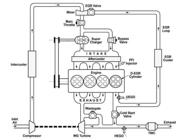
FIGURE 2.13 Schematic of SwRI D-EGR engine system.
SOURCE: Alger (2014). Reprinted with permission, Southwest Research Institute ©2013. All Rights Reserved.
by approximately 10 percent (Alger 2014), as shown in Table 2.36. These improvements do not involve engine downsizing; instead, significant portions of the improvements are attributable to the increase in compression ratio by 2.5 ratios and the addition of high rates of EGR as a diluent for combustion.
PSA Peugeot Citroën recently disclosed that it will commercialize high-efficiency gasoline engines with D-EGR, derived from the SwRI program (Green Car Congress 2013a). The new engines, expected to be available in Europe by 2018, will consume 10 percent less fuel than their predecessors, according to PSA. The estimated cost of $67 per percent fuel consumption reduction for the D-EGR system is higher than that of a turbocharged, downsized engine-level 2 with cooled EGR-level 1, but D-EGR has shown greater fuel consumption reduction effectiveness values in limited tests with experimental hardware. Some technical features of the D-EGR system may serve as enablers for increasing the effectiveness of other SI engine technologies, such as compression ratio increase and downsized, turbocharged engines.
Variable Compression Ratio
Variable compression ratio (VCR) is a technology that adjusts the compression ratio of an engine during operation to increase thermal efficiency while operating under varying loads. Lighter loads benefit from higher ratios to be more efficient while lower compression ratios are required at higher loads to prevent knock. Variable compression ratio engines change the volume above the piston at top dead center. The change is done dynamically in response to the load and driving demands. As turbochargers are used to increase the specific output of downsized engines, VCR becomes more desirable as an enabler for even higher boost pressures. Since some changes in effective compression ratio can be achieved with VVT, the improvements that might be obtained with VCR may be diminished. Nevertheless, several VCR concepts have recently been investigated. Some of these are shown in Figure 2.14 and are described in further detail in Appendix O. Several OEMs indicated that they are conducting research on VCR engines, but no technical details, future plans, or preferred approaches were provided.
TABLE 2.36 D-EGR Vehicle Demonstration
| 2012 Buick Regal | Engine Disp | Compression Ratio | Boost System | Trans | FTP (mpg) | HWFET (mpg) | |||||||||||||
| Production EPA Certification Dataa | 2.0L | 9.2:1 | TC | MT | 23.5 | 37.4 | |||||||||||||
| D-EGR System SwRI Data | 2.0L | 11.7:1 | TC + SC | MT | 25.7 | 40.2 (Est)b | |||||||||||||
| Change (%) | 9.5% | 10.7% | |||||||||||||||||
a 2012 MY.
b Based on % change provided by SwRI.
SOURCE: Alger (2014).
The MCE5 Development (S.A.) Company was established in 2000 in Lyon, France, with the objective of developing VCR engine technology. MCE-5 has developed a multicylinder engine, which has been installed in demonstration vehicles. The compression ratio can be varied continuously from 6:1 to 15:1. A schematic of the MCE-5 technology is shown in Figure 2.14. The MCE-5 technology was also used in the Peugeot (PSA) system, and MCE-5 is reported to be working with many of the other European OEMs (MCE-5 2013). MCE-5 reported that the VCR engine provided a 5 percent reduction in fuel consumption on the NEDC test cycle. MCE-5 indicated that its technology would result in an additional cost of approximately $896 for a four-cylinder engine, which translates into a 2025 direct manufacturing cost of $597 (2010 dollars) by applying an ICM of 1.5.
Variable Displacement Engine
An ideal variable displacement engine would be able to adapt its displacement depending on the power demand, thereby minimizing pumping and friction losses incurred with light load operation of conventional engines. One approach for achieving a variable displacement engine is cylinder deactivation, previously discussed in this chapter. However, cylinder deactivation does not eliminate all of the pumping and friction losses associated with the larger displacement engine. Several concepts have been proposed for a fully variable displacement engine.
Numerous organizations have recently explored concepts for truly variable displacement engines. Evaluations of their potential are often based on theoretical analyses. Two recent examples of such concepts are discussed in this
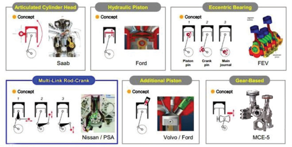
FIGURE 2.14 Variable compression ratio concepts.
SOURCE: Lee et al. (2011); MCE-5.
section, but the literature contains many other concepts for variable displacement engines, some of which have been evaluated by others and rejected as not feasible for a variety of technical reasons. Many challenges and technical hurdles exist that must be resolved before the fuel economy potential of an experimental variable displacement engine can be demonstrated.
Scalzo Automotive Research Pty Ltd is developing a concept called a Piston Deactivation Engine (PDE). This concept has been incorporated in an experimental 1.7L three-cylinder PDE that can operate with one, two, or three cylinders. This concept allows the piston of the deactivated cylinder to be stopped, or “parked,” when not required, unlike the cylinder deactivation engines, where the pistons continue to operate through their full stroke. Figure 2.15.1 shows the engine in the active position, with a conventional crankshaft connected to the piston through an oscillator, which is a rocking, adjustable four-bar mechanism located on the opposite side of the cylinder relative to the crankshaft. Figure 2.15.2 shows the piston in the “parked” position. By rotating the adjustor relative to the oscillator, the lower pin of the piston connecting rod is positioned to be concentric with the rotational axis of the oscillator so that the piston motion is reduced to zero. Scalzo has estimated a reduction in fuel consumption in excess of 30 percent (Boretti and Scalzo 2011). Moreover, Scalzo has estimated an additional 5 to 10 percent fuel consumption reduction with the addition of VCR and a 10 to 15 percent fuel consumption reduction with the addition of both VCR and turbocharging. However, test data are not available to confirm these estimates by Scalzo. Future development plans for this engine concept have not been disclosed.
Another concept for a variable displacement engine has been proposed by Engine Systems Innovation, Inc. (ESI). This engine concept, which is configured in the form of a barrel or axial engine, is shown in Figure 2.16. Variable displacement is achieved by axially moving the carrier along the crankshaft. Moving the carrier axially to the left decreases the displacement of the engine and, at the same time, decreases the angle of oscillation of the nutator so that compression ratio can be maintained or appropriately modified at the reduced displacement. ESI has used the GT-Power engine simulation model to estimate that the VDE engine could provide a 23 percent reduction in fuel consumption relative to a baseline naturally aspirated engine. Hardware development plans for this engine concept have not been disclosed. However, since prototype engines demonstrating the estimated reductions in fuel consumption are not available, VDE technology is unlikely to have an impact on CAFE by 2025 or 2030.
Camless Valvetrain
Improvements in fuel consumption, torque, and emissions are projected to be achieved with flexible control of the valve timing, duration and lift. Camless valvetrains have long been investigated by numerous vehicle manufacturers, suppliers, and consulting engineering companies, and their studies have been extensively documented in technical publications. Some of these researchers have suggested that a camless valvetrain could provide 10 to 20 percent reduction in fuel consumption relative to a conventional cam and valve system with fixed timing. However, measured test results have not confirmed these early projections.
There are two concepts that have been considered for a camless valvetrain. One concept uses electrohydraulic valve actuation, under development by Sturman Industries, and the other uses electromagnetic valve actuation, under development by Valeo (Green Car Congress 2011a). None
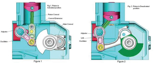
FIGURE 2.15 Scalzo variable displacement engine (VDE).
SOURCE: Scalzo (2014).
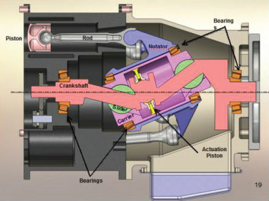
FIGURE 2.16 ESI variable displacement engine in a barrel or axial configuration.
SOURCE: Arnold (2014). Courtesy of Engine Systems Innovation, Inc. Continuously Variable Displacement Engine, US Patent 8,511,625.
of the investigated systems have progressed to a production status. This may be due to several factors. First, VVT and continuously variable valve lift systems can achieve many of the functional capabilities of a camless valvetrain. Second, many problems have been identified during the research and development of camless engines. These problems include high power consumption, accuracy at high speed, temperature sensitivity, weight and packaging issues, high noise, high cost, and undesirable engine failure modes in case of electrical problems.
Another approach to a camless valvetrain is under development by U.K.-based Camcon (Birch 2013). This system, called Intelligent Valve Actuation (IVA), is being designed to allow valve events (lift, timing, and period) to be optimized for every speed and load condition. This system uses a desmodromic valve gear for each valve. Since each valve is actuated by a cam, it is not a “camless” system, although conventional camshafts are eliminated. For full valve lift, an actuator rotates the cam to maximum lift and continues down the other side of the cam lobe and back to the valve closed position. For partial lift, the cam is partially rotated to achieve the target lift and then is returned to its base position. Camcon uses its proprietary Binary Actuation Technology (BAT) to provide the required multidirectional rotation and position control of the cam. Camcon has claimed a 15 percent improvement in fuel economy, which is considerably more than NHTSA’s 3.6-4.9 percent estimate for VVL and 4.1-5.5 percent for dual (intake and exhaust) cam phasing. Fuel consumption results or estimated costs for the system applied to an engine are not available. Camcon is reported to be seeking a supplier to commercialize the system.
Waste Heat Recovery
Approximately one-third of the fuel energy supplied to an SI gasoline engine is lost as exhaust enthalpy, and another one-third is lost as heat rejected to coolant. Therefore, recovering a portion of this energy continues to receive attention in research efforts to improve the efficiency of passenger cars. Turbocharged engines already employ a form of exhaust energy recovery by extracting exhaust energy to drive the compressor to provide more airflow to the engine for increased power. Beyond turbocharging, current research on waste heat recovery is focusing on thermoelectric generators (TEG) and organic Rankine cycle (ORC) systems (Saidur et al. 2012). It should be noted that all waste heat recovery systems rely on a low-grade heat source, meaning that the temperature differentials are not very large and thus tend to have low efficiency potential.
A thermoelectric generator (TEG) converts thermal energy from different temperature gradients between the hot and cold ends of a semiconductor into electric energy. The primary challenge in using a TEG is its low thermal efficiency, which is typically less than 4 percent (Saidur et al.
2012), but future thermoelectric materials have the potential to reach higher efficiencies and power densities (Karri et al. 2011). Materials to improve the conversion efficiency of TEGS, like BiTe (bismuth telluride), CeFeSb (skutterudite), ZnBe (zinc–beryllium), SiGe (silicon–germanium), SnTe (tin telluride) and new nanocrystalline or nanowire thermoelectric materials, are currently in the development stage.
DOE has had continuing research programs on the use of TEGs for waste heat recovery from internal combustion engines. In 2011, DOE completed the installation of TEG systems in BMW (X6) and Ford (Lincoln MKT) vehicles (LaGrandeur 2011). At 65 mph, the Ford vehicle generated approximately 450 W of electrical power at an exhaust temperature of approximately 250°C. Over 700 W of electrical power were generated at an exhaust temperature of approximately 500°C. Assuming the Ford vehicle requires approximately 15 kW of engine power at 65 mph, and assuming that the 450 W of power output from the TEG could be converted to 360 W of mechanical power (assuming 80 percent conversion efficiency), then the fuel consumption of the Ford vehicle could potentially be reduced by approximately 2.5 percent. In October 2011, DOE initiated a follow-on to the TEG program for passenger vehicles with the objective of achieving a 5 percent improvement in fuel economy over the US06 drive cycle and determining the economic feasibility of manufacturing TEG systems in quantities of 100,000 per year. Honda has reported that a TEG containing the appropriate combination of elements with different temperature properties could provide about a 3 percent improvement in fuel economy (Mori et al. 2011). At an estimated cost of $1.00/W, a TEG capable of 700 W would have an estimated direct manufacturing cost of $700 (Green Car Congress 2014a).
Another waste heat recovery system is the organic Rankine bottoming cycle. Because of the low-grade heat sources, the efficiency of the cycle depends on the selected working fluids and operating conditions of the system. Over the last 10 years, interest in the Rankine bottoming cycle has prompted some automotive manufacturers to investigate its potential. Researchers have reported that Honda and BMW (Turbosteamer) have achieved a decrease in fuel consumption of approximately 10 percent for passenger cars (Endo et al. 2007; Freymann et al. 2008). However, little information on ORCs has been available in the past 5 years, suggesting that further development of ORCs has slowed, making it unlikely that they could reach production status for light-duty vehicles by 2025 (even though development continues for heavy-duty applications).
Exhaust heat recovery systems have been reported to provide reductions in fuel consumption ranging from marginal to 4 percent (assumed to be on the FTP75 drive cycle). Issues associated with TEG are that the TEG unit in the exhaust increases back pressure (which lowers output and reduces efficiency), the energy output during the test cycles will be much less than 450 W, and the materials costs are high. Another use of waste heat recovery is to use exhaust heat for rapid warm-up of the engine and transmission oil to reduce friction, as discussed earlier in this chapter in the section “Engine Friction Reduction.”
CONTROL SYSTEMS, MODELS, AND SIMULATION TECHNIQUES
Control systems, models, and simulation techniques are enablers for many of the fuel consumption reduction technologies considered by NHTSA and EPA in their analysis. Current and future engines have a large number of control variables, which must be optimized to realize the maximum reduction in fuel consumption consistent with other vehicle requirements, including the control of emissions and acceptable driveability. Powertrain control systems are expected to be interfaced in the near future with traffic information, navigation systems, and vehicle-to-vehicle communications for more efficient and safe vehicle operation. Controls are important to consider since they are central to the implementation of so many of the technologies considered to improve fuel economy. Though these are discussed here with the SI technologies, they are also important when considering compression ignition diesel engine technologies, electrified powertrains, and improved transmission, which are discussed in Chapters 3-5. As discussed at the conclusion of this section, a shortage of human resources in this area might impact launches of fuel reduction technologies that require sophisticated controls.
Traditional SI engine control systems used classical single-input, single-output (SISO) controllers, which could be optimized independently using proportional-integral-derivative (PID) controllers and were tuned for fast and robust regulation to specified setpoints. Examples of setpoints include (1) idle speed controlled by the throttle actuator, (2) air-to-fuel ratio controlled by the pulsewidth of the fuel injectors, and (3) knock control managed by the spark timing. The control typically consists of constant values of the setpoints, the gains for the PID controllers, and the feedforward map of the actuator to provide fast response during changes in speed and load conditions. The addition of new technologies with new degrees of freedom for engine optimization has led to the significant growth of control variables. Some of the primary control variables in current engines may include the following:
- Air fuel ratio,
- Direct fuel injection timing and duration for multiple injections,
- Spark timing with multiple ignition strikes,
- Intake cam phasing and duration,
- Exhaust cam phasing and duration,
- Intake valve lift,
- Boost pressure with turbocharger wastegate or variable turbine nozzles (VTN),
- Cooled EGR rate,
- Cylinder deactivation, and
- Interface with transmission and vehicle controls.
Each of these variables influences fuel consumption and emissions and consequently must be precisely controlled over the engine’s operating range. Developing the control strategy for these variables requires the use of automated optimization techniques. Applying optimization techniques requires the development of a multidimensional map of the engine, which provides the steady-state fuel consumption and emissions as functions of the above variables. From this map, an analytical model is developed in which fuel consumption and emissions are expressed as functions of the above variables as well as engine speed and load. Using this model, optimization techniques are applied to minimize fuel consumption while complying with other constraints for emissions and driveability. Commercially produced techniques, such as Matlab’s Model-Based Calibration Toolbox, are available for the entire process from mapping the engine through final optimization. Extremum seeking (ES) techniques have also been developed to locate optimum operating points in minimum time without having detailed maps or response surfaces (Popovic et al. 2006). Final chassis dynamometer and on-road testing are required to calibrate and modify the models if necessary.
In addition to defining the setpoint maps for scheduling the control variables at steady state, the transition from one setpoint to the next must be designed using dynamic models and model-based control. Controlling the transition from one setpoint to another for many air path and combustion states is critical for achieving good drivability as well as meeting increasingly stringent emission levels with optimized fuel economy. The complexity associated with dynamic subsystem interaction needs to be accounted for early in the control design process. In some cases, hierarchical controllers impose master-slave sequences of actions depending on the control authority and the bandwidth of the actuators. Nonlinear phenomena in the air path, the combustion process, and the exhaust aftertreatment system are intensified by actuator and sensor saturation and require advanced gain-scheduling approaches.
Architectures, components, and sensors are being optimized to handle the increase in control system complexity. Virtual sensors, also known as estimators, are being developed to replace hardware sensors for cost reductions and improved reliability by eliminating sensors that are often located in hostile environments. A potential candidate for a virtual sensor, which is facilitated by advanced processors, is exhaust temperature, which can be calculated from real-time transient heat transfer analyses. Alternatively, real sensors may be augmented with model-based estimators for increasing the measurement speed of response, filtering sensor noise, or, possibly, providing redundancy for on-board diagnostic functions.
Simulation techniques permit the design of control systems before prototype hardware is available. Engine simulation models, such as GT-Power, have been modified to run in real time so that transient control systems can be developed in parallel with the development of prototype engine hardware (Gamma Technologies n.d.). Real-time models, applied to hardware in the loop systems, have facilitated the development of control systems where the “hardware” may progress from the microprocessor or engine control unit (ECU) to the actual engine on a dynamometer for final optimization.
System partitioning is being altered to reduce cost and packaging. Use of the Controller Area Network (CAN) to transfer control signals from non-powertrain modules to the engine control unit has resulted in the elimination of some sensors. Faster microprocessors have saved space with the consolidation of previously distributed microprocessors and the application of virtual sensors. As modern automotive control approached 20 million lines of software code in single microprocessors, formal verification methods are necessary to confirm the functionality of control systems.
As illustrated in this section, the complexity of powertrain control systems has been intensifying due to the added features described in this chapter and the need for overall systems optimization. Other vehicle systems are also experiencing similar growth. As a result, North American vehicle manufacturers and suppliers have a critical need to find and hire many types of engineers, including mechanical, software, electrical, and manufacturing (Sedgwick 2013). Software engineers are in particularly high demand. This high demand is putting strain on the engineering resources of vehicle manufacturers and suppliers and might impact new vehicle launches containing fuel consumption reduction technologies. The manufacturers and suppliers are competing with Silicon Valley for the software, electrical, and control engineering talent.
FUTURE EMISSION STANDARDS FOR CRITERIA POLLUTANT EMISSIONS
EPA finalized the Tier 3 emission and fuel rules in April 2014. These standards are designed to reduce air pollution from passenger cars and trucks (EPA 2014b) and are important to consider since they may make a possible fuel economy technology more difficult or more expensive to implement, or they may enable other technologies. Though these standards are discussed here with the SI engine technologies, they are also important when considering compression ignition (CI) diesel engine technologies discussed in Chapter 3.
Starting in 2017, the Tier 3 rule sets new vehicle emission standards and lowers the sulfur content of gasoline. EPA established new tailpipe emission standards for the sum of non-methane organic gases (NMOG) and nitrogen oxides (NOx), presented as NMOG + NOx, and for PM that would apply to all light-duty vehicles, as shown in Table 2.37. The proposed NMOG and NOx tailpipe standards for light-duty
| Model year | Table I-1 Tier 3 LDV, LDT, and MDPV Fleet Average FTP NMOG+NOx Standards (mg/mi) | ||||||||||||||||||
| 2017a | 2018 | 2019 | 2020 | 2021 | 2022 | 2023 | 2024 | 2025 and later | |||||||||||
| LDV/LDT1b | 86 | 79 | 72 | 65 | 58 | 51 | 44 | 37 | 30 | ||||||||||
| LDT2,3,4 and MDPV | 101 | 92 | 83 | 74 | 65 | 56 | 47 | 38 | 30 | ||||||||||
a For LDV and LDTs above 6,000 lbs GVWR and MDPVs, the fleet average standards apply beginning in MY 2018.
b These standards apply for a 150,000 mile useful life. Manufacturers can choose to certify some or all of their LDVs and LDT1s to a useful life of 120,000 miles. If a vehicle model is certified to the shorter useful life, a proportionally lower numerical fleet-average standard applies, calculated by multiplying the respective 150,000 mile standard by 0.85 and rounding to the nearest mg.
| Model year | Table I-3 Phase-in for Tier 3 FTP PM Standards (mg/mi) | ||||||||||||||||||
| 2017a | 2018 | 2019 | 2020 | 2021 | 2022 and later | ||||||||||||||
| Phase-in (percent of U.S. sales) | 20b | 20 | 40 | 70 | 100 | 100 | |||||||||||||
| Certification Standard (mg/mi) | 3 | 3 | 3 | 3 | 3 | 3 | |||||||||||||
| In-Use Standard (mg/mi) | 6 | 6 | 6 | 6 | 6 | 3 | |||||||||||||
a For LDV and LDTs above 6,000 lbs GVWR and MDPVs, the fleet average standards apply beginning in MY 2018.
b Manufacturers comply in MY 2017 with 20 percent of their LDV and LDT fleet under 6,000 lbs GVWR, or alternatively with 10 percent of their total LDV, LDT, and MDPV fleet.
SOURCE: EPA (2014b).
vehicles represent approximately an 80 percent reduction from today’s fleet average and a 70 percent reduction in per-vehicle PM standards. EPA is extending the regulatory useful life period during which the standards apply from 120,000 miles to 150,000 miles. EPA is also implementing more stringent evaporative emission standards, which represent about a 50 percent reduction from current standards.
NMOG + NOx Standards
Fleet-average NMOG + NOx emissions are calculated by the manufacturer, using weighted average emissions of each model year’s vehicles. This, in turn, is compared with the pertinent standard for the given model year. Proposed NMOG + NOx standards for light-duty vehicles and trucks, defined as vehicles below 8,500 lb Gross Vehicle Weight Rating (GVWR), and medium-duty passenger vehicles, defined as vehicles between 8,500 and 10,000 lb GVWR, are as follows:
- 30 mg/mi, as determined using the US06 (high-speed, high-acceleration) component of the Federal Test Procedure (FTP), by 2025. Today’s fleet average is 160 mg/mi.
- 50 mg/mi, as determined using the Supplemental Federal Test Procedure (SFTP), by 2025. The current fleet average is roughly 200 mg/mi.
PM Standards
The PM standards are applied to individual vehicles separately, on a per-vehicle basis, rather than applied as a fleet average. PM standards for LDVs, LDTs, and MDPVs are as follows:
- As determined on the FTP, the standard is 3 mg/mi for all vehicles and model years beginning with 20 percent of the fleet in 2017 and rising to 100 percent of the fleet in 2021. For reference, the current standard is 10 mg/mi.
- As determined using the US06 component of the SPTP, the PM standard through 2018 is 10 mg/mi and 6 mg/mi for 2019 and later model years.
Fuel Standards
Gasoline sulfur reductions finalized by EPA will make emission control systems more effective and assist manufacturers in complying across the fleet. In addition, the gasoline sulfur standards would bring substantial immediate benefits because they would result in reduced emissions for existing vehicles. In order to meet federal standards, EPA will require an annual average standard of 10 ppm of sulfur by January 1, 2017. Also, the present 80 ppm refinery gate and 95 ppm downstream cap are to be maintained by EPA. The Tier 3 gasoline sulfur standards are consistent with levels already reached in California, Europe, Japan, and South Korea, among others.
Changes to Emissions Test Fuel
The test fuel used in the federal emissions tests is being updated by EPA in order to more realistically match cur-
rent in-use gasoline. This also allows for adjustments that may account for anticipated sulfur and ethanol content. The updated test fuel will be 10 percent ethanol by volume (the present test fuel is 0 percent ethanol) and will also have reduced octane and sulfur (to bring it in line with the Tier 3 specifications). Octane will be lowered to around 87 AKI (R+M)/2 to be representative of in-use fuel. In addition, EPA is specifying the first test fuel requirements for E85.
Because ethanol has a lower heating value than gasoline (76,330 Btu/gal vs. 116,090 Btu/gal) and the CAFE fuel economy is defined in terms of miles per gallon of fuel, the same vehicles tested with gasoline having 10 percent ethanol will yield approximately 3.4 percent lower fuel economy than those tested with gasoline having zero ethanol content. For CAFE purposes, an existing fuel economy equation for gasoline, which has been used since 1988, includes modification to the value of the test fuel energy content. This modification is applied in order to determine what the fuel economy would be if the 1975 baseline test fuel was used (Memorandum to Tier 3 Docket 2013). This equation contains an “R-factor,” which is employed because the fuel economy difference is not linearly proportional to the difference in the test fuel’s heating value. Since 1988, an R-factor of 0.6 has been employed. However, EPA is currently investigating the suitability of this value.
The proposed Tier 3 emission standards are similar to the California LEV III emission standards that were approved in January 2012. Therefore, the impact of the Tier 3 standards on vehicle technologies would apply equally to the California LEV III standards discussed in the next section. The proposed fuel standard, which would reduce sulfur to 10 ppm, was considered more of an enabler for higher mileage durability than an enabler for the introduction of lean burn. Only one manufacturer specifically cited the proposal as a possible enabler for lean burn, strongly dependent on the downstream fuel sulfur levels at the pump.
Technologies
Tier 3 emission control technologies identified by EPA for large light-duty truck applications are shown in Figure 2.17. Large LDTs will face greater difficulty than other LDVs in meeting the Tier 3 NMOG + NOx standards at the 30 mg/mi level. For this vehicle segment, the technologies identified by EPA to provide the 77 percent reduction in emissions, taking into account compliance margins, are these: addition of a hydrocarbon adsorber, reduced thermal mass, increased catalyst active materials, secondary air injection, and calibration changes. Catalyst efficiencies for NOx and NMOG when going from Tier 2 to Tier 3 levels reflect the beneficial effects of reducing gasoline sulfur levels to 10 ppm (from a level of 30 ppm). Compliance margins were reduced from 60 to 50 percent in going from Tier 2 to Tier 3 standards to account for anticipated improvement for in-use deterioration and variability.
The Tier 3 final rule states that EPA does not expect the Tier 3 emission standards to result in “any discernible changes in vehicle fuel economy” (EPA 2014b). However, applying the following three emission control technologies suggested in the final rule could result in less than a 0.5 percent increase in fuel consumption, as described in Appendix P. Secondary air injection for oxidation of unburned HC emissions may be implemented using an electrically driven air pump requiring approximately 100 W for the first 60 seconds of the FTP test cycle, resulting in approximately a 0.015 percent increase in fuel consumption. The addition of a hydrocarbon adsorber for controlling cold start HC emissions will increase back pressure, which could result in approximately a 0.06 percent increase in fuel consumption. Calibration changes consisting of spark retard and increased idle speed for 30 seconds for faster catalyst warm-up could result in approximately a 0.24 percent increase in fuel consumption. Although the combined magnitude of these increases in fuel consumption is expected to be small, they will nevertheless increase the task of complying with the CAFE standards. Tier 3 gasoline sulfur standards may be an enabler for lean burn technology to provide a reduction in fuel consumption, although few vehicle manufacturers revealed lean burn in their future CAFE plans.
California LEV III Standards
“Advanced Clean Car Rules,” a set of car and light-duty truck emissions rules through 2025, was approved by the California Air Resources Board in January 2012. The rules will be gradually phased in, and they will include
- LEV III amendments to California Low Emission Vehicle regulations. Two regulations are bundled together under the LEV III cover:
- — LEV III emission standards for criteria emissions for vehicle MY 2015-2025 and
- — GHG emission standards for vehicle MY 2017-2025.
- ZEV (zero emission vehicle) regulation.
- Clean fuel outlets regulation.
California’s LEV III emission standards, shown in Table 2.38, are very similar to the Tier 3 standards, with the exception of the PM standard, which is reduced to 1 mg/mi by 2028. The committee found that some manufacturers thought that the 3 mg/mi PM standard could be met without a gasoline particulate filter (GPF). However, there may be a possibility, particularly with gasoline direct injection engines, that the 1 mg/mi PM standard would require a GPF, with an associated increase in fuel consumption due to additional exhaust back pressure on the engine and the possible need for periodic regeneration of the collected particulate matter.
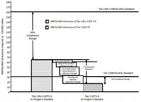
FIGURE 2.17 Tier 3 emission technologies for large, light-duty truck compliance.
SOURCE: EPA (2013).
TABLE 2.38 California LEV III Emission Standards
| LEV III Emission Standards, Durability 150,000 miles, FTP-75 | |||||||||||||||||||
| Vehicle Types | Emission Category | NMOG+NOx (g/mi) | CO (g/mi) | HCHO (mg/mi) | PMa (g/mi) | ||||||||||||||
| All PCs, | LEV160 | 0.160 | 4.2 | 4 | 0.01 | ||||||||||||||
| LDTs ≤ 8500 lbs GVW, and All MDPVs | ULEV125 | 0.125 | 2.1 | 4 | 0.01 | ||||||||||||||
| ULEV70 | 0.070 | 1.7 | 4 | 0.01 | |||||||||||||||
| ULEV50 | 0.050 | 1.7 | 4 | 0.01 | |||||||||||||||
| SULEV30 | 0.030 | 1.0 | 4 | 0.01 | |||||||||||||||
| SULEV20 | 0.020 | 1.0 | 4 | 0.01 | |||||||||||||||
SOURCE: DieselNet (2013).
Wide Range of Fuels Makes It Harder to Calibrate for Fuel Economy
Gasolines are defined by regulations in which properties and test methods are clearly specified. Several government and state bodies are responsible for defining U.S. gasoline standards. Standards have been developed by the American Society for Testing Materials (ASTM), the Society of Automotive Engineers (SAE), the U.S. Environmental Protection Agency (EPA), and the California Air Resources Board (CARB) (Hamilton 1996). These standards are used to directly reduce emissions or enable technologies that reduce emissions. Several examples of EPA’s standards for gasoline are listed in Appendix Q.
The recommended gasoline for most cars is regular 87 AKI. A fuel’s octane rating is representative of the unburned end gases’ ability to resist spontaneous autoignition. The driver of a vehicle has the responsibility to fuel the vehicle with the AKI rating recommended in the owner’s manual for the given engine. The AKI rating must be displayed on a yellow sticker on the gas pump. If fuel with suboptimal octane rating is used, combustion may be less efficient than it would be with the optimal octane level. If this occurs, power and fuel economy will be adversely affected.
Engines are usually calibrated using the fuel that will be recommended in the owners’ manual. Calibrations generally use fixed values for control parameters, such as spark timing, based on engine mapping test results that provide optimum fuel economy. The exception to this is the use of a sensor to detect knock at high loads so that the spark timing can be retarded to protect the engine from catastrophic damage. This calibration process generally results in approaching the optimum fuel economy for the specific engine, transmission, and vehicle hardware.
Impact of Low Carbon Fuels on Achieving Reductions in GHG Emissions (California LCFS 2007—Alternative Fuels and Cleaner Fossil Fuels CNG, LPG)
The low-carbon fuel standard (LCFS) is a rule that was enacted by California in 2007 and is the first low-carbon fuel standard mandate in the world. The LCFS directive requires that, by 2020, California’s transportation fuels will decrease in carbon intensity by 10 percent. Decreased emissions from the tailpipe, as well as all other production and distribution emissions and any other emissions associated with the use of transport fuels in California, will contribute to the 10 percent reduction. As such, the entire life cycle of the fuel is affected by the California LCFS, making the standard a “well-to-wheels” or “seed-to-wheels” emission standard. Details of the LCFS and the approaches being considered for achieving LCFS compliance are discussed in Appendix R.
Importance of Alternative Fuels Infrastructure
As noted in this and later chapters, there are several vehicle technologies that are dependent on alternative fuels. The success of these technologies will be dependent on the infrastructure for these fuels.
There has been noteworthy industry investment in infrastructure for refueling with natural gas in transportation applications. There were 1,242 CNG and 74 LNG fueling stations in the United States as of September 2013 (AFDC n.d.). Clean Energy Fuels and Pilot Flying J truck stops are building America’s Natural Gas Highway, a national network of natural gas refueling stations. Seventy of the planned 150+ stations had been constructed by February of 2013. Clean Energy also constructed 127 stations in 2012. These stations have varied uses, including applications associated with transportation, waste, and aviation. Shell and Travel Centers for America have reached an agreement for Shell to construct natural gas filling stations at up to 100 travel centers. The California Energy Commission (CEC), through the Alternative and Renewable Fuel and Vehicle Technology Program, has contributed more than $16 million to infrastructure for natural gas refueling.
Advanced vehicle technologies may also consume the alternative fuels electricity and hydrogen. Plug-in electric vehicles (PEVs) and fuel-cell vehicles (FCVs) employ, respectively, electricity and hydrogen, which promise to be important components of LCFS compliance, especially as the program reaches maturity.
Importance of Treating Vehicle Technology and Fuels as a System
It has long been recognized that vehicle technology and fuels are a system. In the earliest days of the automotive industry, achieving compatibility of engines and available fuels resulted in compression ratios as low as 4.5:1 in the 1908 Ford Model T. Through the ongoing development of fuels and engines, compression ratios have increased to the range of 9:1 to 11:1 with 87 AKI fuels, resulting in significant improvements in engine thermal efficiencies.
The efforts to achieve compatibility of engines and fuels have been fostered by the OEMs as well as several organizations, including the Society of Automotive Engineers (SAE) and the Coordinating Research Council (CRC). SAE fosters the exchange of information through their Fuels and Lubricants, Engines, Alternative Powertrains and other vehicle-related organizations and associated journals. The CRC aims to encourage cooperative science research in order to advance the improved blends of fuels, lubricants, and associated equipment. Also, the CRC promotes cooperation with the government on issues that are relevant on a national or international scale. The Sustaining Members of CRC are the American Petroleum Institute (API) and a group of automobile manufacturers (Chrysler, Ford, General Motors, Honda,
Mitsubishi, Nissan, Toyota, and Volkswagen). The Alliance of Automotive Manufacturers (AAM) reiterated that the EPA Tier 3 emission standards must continue to treat vehicles and fuels as a system (AAM 2013).
The 2017-2025 CAFE standards will lead to further efforts to ensure compatibility of engines and fuels. Some examples where engines and fuels will need to continue to be treated as systems include the following:
- Any high BMEP engines will need to be developed as a system with available and future anticipated fuels.
- The further reduction of sulfur may enable the application of lean burn engines with suitable lean NOx aftertreatment.
- The possibility of E30 as a commercial fuel, as suggested by the option to use E30 as a certification fuel in the Tier 3 standards, or the availability of higher octane gasolines, may facilitate the development of higher compression ratio engines.
- The continuing research into low-temperature combustion (LTC) processes, such as HCCI or SACI processes, will rely on the autoignition characteristics of available fuels.
The OEMs that the committee met with were focused on treating vehicles and fuels as a system.
Finding 2.1 (Overall Fuel Consumption Reduction Effectiveness and Costs) Spark ignition engines are dominant in light-duty vehicles today and are expected to remain dominant, with further reductions in fuel consumption beyond 2025. Spark ignition engine technologies combined (improved lubricants, lower engine friction, variable valve timing and lift, direct injection, cooled exhaust gas recirculation and downsizing/turbocharging) were estimated to provide an overall reduction in fuel consumption of 27 to 28 percent from the null vehicle, which is within the range of NHTSA’s estimates. For an example midsize car, the spark ignition engine technologies that might be applied in the 2017 to 2025 time frame were estimated to provide approximately a 17 to 18 percent reduction in fuel consumption and these technologies had a cumulative direct manufacturing cost of approximately $526 to $705. These results will vary with vehicle type, engine type, and the vehicle manufacturer’s overall CAFE compliance plan.
Finding 2.2 (Fuel Consumption Reduction Effectiveness Compared to EPA and NHTSA) EPA and NHTSA defined the fuel consumption reduction effectiveness of technologies relative to a spark ignition engine in a null vehicle. NHTSA also defined effectiveness relative to previous technologies that had already been applied according to decision tree paths, and these effectiveness values were generally lower due to negative synergies. The committee developed low and high most likely effectiveness estimates relative to the baseline engine of the null vehicle. The committee’s estimates of effectiveness agreed with many of NHTSA’s estimates. For several technologies, the committee’s high estimates agreed with NHTSA’s estimates, while the low estimate for the 18 bar BMEP engine was 1 percentage point lower than the high estimate of 14.9 percent, was 2 percentage points lower than the high estimate of 20.1 percent for the 24 bar BMEP engine, and was 1 percentage point lower than the high estimate of 3.5 percent for cooled exhaust gas recirculation. The low estimates resulted from the following factors: (1) reduced compression ratio for 87 AKI (91 RON) gasoline in the United States, (2) spark retard to preclude knock at elevated boost pressure levels, (3) wider ratio transmissions and/or modified torque converters to compensate for turbocharger lag, (4) reduced effectiveness of EGR, and (5) EPA certification test results.
Recommendation 2.1 (Fuel Consumption Reduction Effectiveness) Full system simulation is acknowledged to be the most reliable method for estimating fuel consumption reductions for technologies before prototype or production hardware becomes available for testing. The committee compliments EPA and NHTSA on initiating their full system simulation programs. For spark ignition engines, these simulations should be directed toward the most effective technologies that could be applied by the 2025 MY to support the midterm review of the CAFE standards. The simulations should use either engine maps based on measured test data or an engine-model-generated map derived from a validated baseline map in which all parameters except the new technology of interest are held constant. Full system simulations for spark ignition engine technologies should be confirmed whenever possible using vehicle results to ensure that fuel octane and drivability requirements have been included.
Finding 2.3 (Cost) The committee developed low and high most likely direct manufacturing cost estimates for the spark ignition engine technologies. The committee’s low estimates agreed with NHTSA’s estimates as did many of the high estimates, while the high estimates were approximately 15 percent higher than NHTSA’s estimated direct manufacturing costs for cam phasing, variable valve lift, and 18 bar BMEP turbocharged, downsized engine. Additional costs of up to nearly $200 may result from turbocharger upgrades for higher temperature operation, ignition upgrades for reliable ignition with cooled exhaust gas recirculation, the addition of torsional vibration dampers to transmissions for smaller displacement engines, and vehicle integration components for noise, vibration, and harshness control and thermal management.
Recommendation 2.2 (Updated Cost Teardown Studies) Since teardown cost studies are acknowledged to be the most reliable cost estimating methodology, and recognizing the
uncertainties in some of the cost studies performed 5 years ago that supported the final CAFE rulemaking, NHTSA and EPA should consider updated teardown cost studies of the latest spark ignition engine technologies identified in the final CAFE rule, as well as cost studies for spark ignition engine technologies anticipated but not currently in production, to support the midterm review of the CAFE standards. Enhanced validation through market testing, in which quotes are obtained from suppliers, should be included in these studies. Vehicle integration costs, including noise, vibration, and harshness control measures, ignition systems upgrades, transmission upgrades with torsional damping, and installation components for engine mounts, heat protection, cooling, wiring and connectors, and other installation requirements should be included in these studies.
Finding 2.4 (Other Technologies by 2025 Not Considered by EPA/NHTSA) Several technologies beyond those considered by EPA and NHTSA might provide additional fuel consumption reductions for spark ignition engines or provide alternative approaches at possibly lower costs for achieving reductions in fuel consumption by 2025. These technologies include (1) higher compression ratio with current regular grade gasoline with an estimated effectiveness of up to 3 percent and a 2025 MY direct manufacturing cost of $50 to $100; (2) higher compression ratio with higher octane regular grade gasoline, if it were to become widely available, with estimated effectiveness of up to 5 percent and a direct manufacturing cost of $75 to $150; (3) high compression ratio with exhaust scavenging and direct injection (also known as Skyactiv, Atkinson cycle) with effectiveness ranging up to 10 percent and a direct manufacturing cost of approximately $250 to $500; (4) electrically assisted, variable-speed supercharger with an effectiveness of approximately 26 percent and a direct manufacturing cost of approximately $1,000 to $1,300; and (5) lean burn facilitated by low-sulfur fuel with an effectiveness of up to 5 percent and direct manufacturing costs of up to $800 to $1,000, although significantly less advantage is expected when compared to an engine with cooled exhaust gas recirculation. Although EPA and NHTSA estimated minimum effectiveness for cylinder deactivation in four-cylinder engines, recent introductions in Europe merit continued investigation of this technology.
Finding 2.5 (Alternative Fuel Technologies) Although alternative fuel technologies have little or even negative effects on miles per gallon gasoline equivalent (mpgge) used to compare energy consumption, several of these technologies may impact CAFE by 2025 by benefiting from application of the Petroleum Equivalency Factor (PEF). Compressed natural gas-gasoline bi-fuel vehicles are already being introduced with the potential to reduce petroleum consumption in these vehicles by up to 43 percent, but at an estimated direct manufacturing cost of up to $6,000 or $7,800, although potentially lower costs could be realized with learning and if higher volumes develop. After 2019, when real-world weighting factors must be applied, the effectiveness of flexible-fuel vehicles for achieving CAFE benefits will likely be significantly reduced. Ethanol-boosted, direct injection engines that are turbocharged and downsized have shown the potential for 20 percent fuel savings relative to baseline engines with a direct manufacturing cost of approximately $750 to $1,000, although the requirement for two fuels significantly diminishes the attractiveness of this concept.
Finding 2.6 (Other Technologies after 2025 Not Considered by EPA/NHTSA) After 2025, several other technologies beyond those considered by EPA and NHTSA might provide additional fuel consumption reductions or alternative approaches for spark ignition engines. These technologies include: (1) variable compression ratio with the potential for 5 percent reduction in fuel consumption and an estimated direct manufacturing cost of $600 to $900; (2) dedicated EGR (D-EGR) with the potential for 10 percent reduction in fuel consumption and an estimated cost of $667; (3) spark assisted, homogeneous charge compression ignition (SI-HCCI) combustion process with a potential for up to 5 percent reduction in fuel consumption relative to a turbocharged, downsized engine and an estimated direct manufacturing cost of approximately $450 to $550 assuming three way catalyst (TWC) aftertreatment; (4) gasoline direct injection compression ignition (GDCI) with up to 5 percent reduction in fuel consumption when applied to a turbocharged, downsized engine and an estimated direct manufacturing cost of approximately $2,500 to $3,750 relative to a baseline engine; and (5) waste heat recovery with the potential for up to 3 percent reduction in fuel consumption and an estimated direct manufacturing cost of approximately $700 to $1,050. Since approximately 60 to 70 percent of fuel energy is lost as heat to coolant or exhaust enthalpy, albeit low quality heat, additional research on waste heat recovery technologies may be called for to determine the estimated benefit of this technology.
Finding 2.7 (HCCI) Homogeneous charge compression ignition (HCCI) for gasoline engines, also known as low-temperature combustion, is estimated to provide up to 5 percent reduction in fuel consumption. HCCI issues include limited range of loads for successful operation and the difficulty of controlling switching between HCCI and SI combustion modes. Recent results from a DOE-sponsored project found that the potential fuel consumption benefit of lean HCCI was eliminated under SULEV (Tier 3 or Tier 2 Bin 2) emission constraints because of the need to switch to a fuel-rich mode after lean operation to deplete the stored oxygen in order to restore the three-way catalyst (TWC) NOx conversion efficiency. Recent research with stoichiometric HCCI and other efforts with multiple direct injections of gasoline to provide partially premixed combustion have extended the range of HCCI to full load on a single-cylinder laboratory engine, and confirmation is under way on a multicylinder engine.
Although HCCI is not likely to have an impact on CAFE by 2025 MY since the technology is still in the laboratory, it might have a role by the 2030 time frame after the full benefits of turbocharged and downsized engines have been realized.
Finding 2.8 (Mazda Skyactiv Technology) Mazda introduced a gasoline engine in 2012 with Skyactiv technology, which consists of enablers that primarily facilitate operation at a high 13:1 compression ratio while using 87 AKI (91 RON) regular gasoline. The enablers of the high compression ratio are enhanced exhaust scavenging and direct injection. Fuel consumption reduction effectiveness is estimated to be up to 10 percent with a direct manufacturing cost of approximately $250. Mazda recently announced plans for its next-generation Skyactiv2 engine, which was claimed to be 30 percent more efficient than the current Skyactiv engine by using a compression ratio of 18:1 and lean HCCI combustion. However, these two features alone are estimated to provide up to 5 to 10 percent additional reduction in fuel consumption. No test results are available to confirm the feasibility or benefits of Mazda’s announced features of the Skyactiv2 engine. Additionally, the compatibility of turbocharging and downsizing with the exhaust scavenging system of the Skyactiv approach is unknown.
Finding 2.9 (High Octane Gasoline) Increasing octane from 87 AKI (91 RON) of regular grade gasoline to 91 AKI (95 RON) has the potential to provide 3 to 5 percent reduction in fuel consumption for naturally aspirated engines if compression ratio is increased by 2 ratios from today’s typical level, and possibly even greater reductions in fuel consumption for turbocharged engines by allowing operation at higher boost pressures for further downsizing. Future availability of ethanol in the United States may raise the ethanol content of gasoline from the current E10 to E15. If the octane of the current gasoline blend stock were to be retained at current levels by the refiners, the increased ethanol content might provide the increase in octane level needed to facilitate higher compression ratio engines. However, regular grade gasoline with a higher minimum octane level would need to be widely available before manufacturers could broadly offer engines with significantly increased compression ratios. EPA’s Tier 3 program, which changes the certification test fuel to E10 with octane representative of today’s level of 91 RON (87 AKI), does not contemplate the above scenario. However, EPA’s Tier 3 program does allow manufacturers to use high-octane gasoline for testing vehicles that require premium if they can demonstrate that such a fuel would be used by the operator.
Recommendation 2.3 (High Octane Gasoline) EPA and NHTSA should investigate the overall well-to-wheels CAFE and GHG effectiveness of increasing the minimum octane level and, if it is effective, determine how to implement an increase in the minimum octane level so that manufacturers would broadly offer engines with significantly increased compression ratios for further reductions in fuel consumption.
Finding 2.10 (Tier 3 Emission Standards) EPA’s Tier 3 emission standards will require approximately an 80 percent reduction in NMOG + NOx emissions and a 70 percent reduction in particulate matter (PM). These standards may result in less than a 0.5 percent increase in fuel consumption due to (1) the possible use of an electrically driven secondary air injection pump; (2) the addition of a hydrocarbon adsorber which would increase back pressure; and (3) calibration changes. Tier 3 gasoline sulfur standards may be an enabler for lean burn technology although few vehicle manufacturers revealed lean burn in their future CAFE plans. Some manufacturers are concerned that California’s LEV III requirement of 1 mg/mi PM by 2028 may require gasoline particulate filters on gasoline direct injection engines.
Finding 2.11 (Off-Cycle Fuel Economy) The relative deviation of real-world fuel economy from CAFE compliance values is expected to increase as more advanced fuel economy technologies defined by EPA and NHTSA are applied to achieve the 2017-2025 MY CAFE targets. Turbocharged, downsized engines may use fuel enrichment at high loads to manage temperatures and spark retard to control knock, both of which will deteriorate fuel economy more than in a larger naturally aspirated engine in on-road conditions.
Finding 2.12 (Critical Need for Engineering Skills) The complexity of powertrains, control systems, and vehicles is accelerating with the addition of multiple fuel consumption reduction technologies and the need for overall systems optimization. New vehicle launches nearly doubled in 2014 over the preceding year. North American vehicle manufacturers and suppliers have a critical need for many types of engineers, including mechanical, electrical, and manufacturing. This high demand is straining the engineering resources and might impact new vehicle launches containing fuel consumption reduction technologies. Vehicle manufacturers and suppliers are competing with other sectors, especially the IT sector, for software, electrical, and control engineering talent.
AAM (Alliance of Automotive Manufacturers). 2013. U.S. EPA Tier 3 Rulemaking and Market Gasoline Standards. Auto Industry Perspective Presentation to OMB, March 22. http://www.whitehouse.gov/sites/default/files/omb/assets/oira_2060/2060_03222013b-1.pdf.
Abuelsamid, S. 2009. Hyundai’s New 2.4l Gdi Four Cylinder Hits up to 200hp in Sonata, 10% More Mpg. Autobloggreen, November 23. http://www.autoblog.com/2009/11/23/hyundais-new-2-4l-gdi-four-cylinder-hits-up-to-200hp-in-sonata/.
AFDC (Alternative Fuels Data Center). n.d. http://www.afdc.energy.gov/data_download/. Accessed September 28, 2013.
Alger, T. 2010. SwRI’s HEDGE Technology for High Efficiency, Low Emissions Gasoline Engines. DEER Conference, September 29.
Alger, T.F. 2014. High Efficiency Engines of the Future. Presentation to the National Research Council Committee on Assessment of Technologies for Improving Light-Duty Vehicle Fuel Economy, Phase 2. Washington, DC, February 13.
Alger, T.F., and B.W. Mangold. 2009. Dedicated EGR: A new concept in high efficiency engines. Presented at the Society of Automotive Engineers Congress, SAE International Technical Paper 2009-01-0694.
Alger, T., B. Mangold, C. Roberts, and J. Gingrich. 2012. The Interaction of fuel anti-knock index and cooled EGR on engine performance and efficiency. SAE Int. J. Engines 5(3):1229-1241. doi:10.4271/2012-01-1149.
Ameri, M. 2010. Energy and exergy analyses of a spark-ignition engine. Int. Journal of Exergy (IJEX) 7(5).
American Petroleum Institute (API). 2010. Determination of the Potential Property Ranges of Mid-Level Ethanol Blends. Washington, D.C.
Arnold, S. 2014. Continuously Variable Displacement Engine. Engine Systems Innovation, Inc. Provided to the National Research Council Committee on Assessment of Technologies for Improving Light-Duty Vehicle Fuel Economy, Phase 2. February 21.
Autoweek. 2013. Honda Goes Turbo with New Engine Family. November 18. http://autoweek.com/article/car-news/honda-goes-turbo-new-engine-family.
Berry, I. 2010. The Effects of Driving Style and Vehicles Performance on the Real-World Fuel Consumption of the U.S. Light–Duty Vehicles. MIT MS Thesis, February.
Bickerstaffe, S. 2012. Ford 1.0 EcoBoost. Automotive Engineer, February 1.
Birch, S. 2013. ‘Valve-by-wire’ gives a lift to combustion technology. SAE Automotive Engineering Magazine, June 17. http://articles.sae.org/12246/.
Birch, S. 2014. Volvo “triple boost” engine uses twin turbos plus e-compressor. Automotive Engineering Magazine, October 23. http://articles.sae.org/13626.
Blaxill, H. 2012. MAHLE Downsizing Demonstrator. Presentation to the National Research Council Committee on Assessment of Technologies for Improving Light-Duty Vehicle Fuel Economy, Phase 2. Dearborn, Michigan, September 27.
Boretti, A., and J. Scalzo. 2011. Piston and valve deactivation for improved part load performances of internal combustion engines. SAE International, Technical Paper 2011-01-0368.
BorgWarner. n.d. eBoost by BorgWarner. http://www.3k-warner.de/products/eBooster.aspx. Accessed August 20, 2013.
Bromberg, L., D.R. Cohn, and J.B. Heywood. 2012a. Alcohol boosted turbo gasoline engines. White Paper for National Petroleum Council Study, MIT and Ethanol Boosting Systems, LLC (EBS).
Bromberg, L., D.R. Cohn, and J.B. Heywood. 2012b. Impact of ethanol blends in SI engines: ‘Increasing the impact of ethanol.’ MIT Plasma Science and Fusion Center and Ethanol Boosting Systems, LLC (EBS). International Workshop on Ethanol Combustion Engines, Sao Paolo, Brazil, October 4.
Brooke, L. 2013. Chrysler Sees the ICE Future. SAE Automotive Engineering International, October 1.
Brown, S.F. 2000. Closing In On the Camless Engine: It Would Save Fuel, Run Cleaner, and Respond Better to the Driver’s Right Foot. Fortune Magazine, May 29.
Cairns, A., and H. Blaxill. 2005a. The effects of combined internal and external exhaust gas recirculation on gasoline controlled authoignition. SAE Technical Paper 2005-01-0133.
Cairns, A., and H. Blaxill. 2005b. Lean boost and exhaust recirculation for high load controlled autoignition. SAE Technical Paper 2005-01-3744.
CARB (California Air Resources Board). 2009. Staff Report: Initial Statement of Reasons: Proposed Regulation to Implement the Low Carbon Fuel Standard. Public Hearing to Consider the Proposed Regulation to Implement the Low Carbon Fuel Standard. Sacramento, California, March 5.
CARB. 2012. California 2015 and Subsequent Model Criteria Pollutant Exhaust Emission Standards and Test Procedures and 2017 and Subsequent Model Greenhouse Gas Exhaust Emission Standards and Test Procedures for Passenger Cars, Light-Duty Trucks, and Medium-Duty Vehicles. Adopted March 22.
Carley, L. 2007. Are You Ready for GF-5 Oils? Underhood Service, January 1. http://www.underhoodservice.com/are-you-ready-for-gf-5-oils/.
Caswell, D.A. 1984. Controlled Variable Compression Ratio Piston for an Internal Combustion Engine. U.S. Patent No. 4,469,055 A, Sept 4.
Chadwell, C., T. Alger, J. Zuehl, and R. Gukelberger. 2014. A Demonstration of Dedicated-EGR on a 2.0 L GDI Engine. SAE Int. J. Engines 7(1): 434-447. doi: 10.4271/2014-01-1190.
Cheah, L., C. Evans, A. Bandivadekar, and J. Heywood. 2007. Factor of Two: Halving the Fuel Consumption of New U.S. Automobiles by 2035. Publication No. LFEE 2007-04 RP.
Chiang, C.J., A.G. Stefanopoulou, and M. Jankovic. 2007. Nonlinear Observer-based Control of Load Transitions in Homogeneous Charge Compression Ignition Engines. IEEE Trans. Control Syst. Technol. 15(3):438-448.
Chow, E. 2013. Exploring the Use of Higher Octane Gasoline for the U.S. Light-Duty Vehicle Fleet, MS Thesis, MIT, June.
Chow, E., J. Heywood, and R. Speth. 2014. Benefits of Higher Octane Standard Gasoline for the U.S. Light-Duty Vehicle Fleet. SAE Technical Paper 2014-01-1961. doi:10.4271/2014-01-1961.
Chrysler. 2013. Written comment regarding the EPA Proposed rule Entitled Control of Air Pollution From Motor Vehicles: Tier 3 Motor Vehicle Emissions and Fuel Standards, published in the Federal Register on May 21, 2013. Docket ID No. EPA-HQ-OAR-2011-0135-4326, July 1. http://www.regulations.gov/#!documentDetail;D=EPA-HQ-OAR-2011-0135-4326.
Coltman, D., J.W.G. Turner, R. Curtis, D. Blake, B. Holland, R.J. Pearson, A. Arden, and H. Nuglisch. 2008. Project Sabre: A Close-Spaced Direct Injection 3-Cylinder Engine with Synergistic Technologies to achieve Low CO2 Output. SAE Paper 2008-01-0138.
Colucci, J. 2012. Improving Auto Fuel Economy via Fuel Changes. Presentation to the National Research Council Committee on Assessment of Technologies for Improving Light-Duty Vehicle Fuel Economy. Dearborn, Michigan, December 3.
Colucci, J. 2013. Higher Octane: Opportunities, Challenges, and Pathways towards Market Introduction. Presentation to SAE International High Octane Fuels Symposium. Washington, D.C., January 29.
Confer, K. 2014. 2013 DOE Vehicle Technologies Review – Gasoline Ultra Fuel Efficient Vehicle. DOE Merit Review ACE064, May 17.
Confer, K., J. Kirwan, M. Sellnau, J. Juriga, and N. Engineer. 2012. Gasoline Ultra Fuel Efficient Vehicle Program Update. DOE DEER Conference, October 16.
Confer, K.A., J. Kirwan, and N. Engineer. 2013. Development and Vehicle Demonstration of a Systems-Level Approach to Fuel Economy Improvement Technologies. SAE 2013-01-0280. doi:10.4271/2013-01-0280.
Cruff, L., M. Kaiser, S. Krause, H. Roderick et al. 2010. EBDI® - Application of a Fully Flexible High BMEP Downsized Spark Ignited Engine. SAE Technical Paper 2010-01-0587. doi:10.4271/2010-01-0587.
Dana. n.d. Active Warm-Up. http://www.dana.com/wps/wcm/connect/dext2/dana/markets/light+vehicle/thermal+management/active+warmup/active+warm-up. Accessed July 22, 2013.
Daw, S., Z. Gao, V. Prikhodko, S. Curran, and R. Wagner. 2013. Modeling Emissions Controls for RCCI Engines. Engine Research Center Symposium, June.
Dick, A., J. Greiner, A. Locher, and F. Jauch. 2013. Optimization Potential for a State of the Art 8-Speed AT. SAE 2013-01-1272.
DieselNet. 2013. Cars and Light-Duty Trucks – California. Emission Standards. http://www.dieselnet.com/standards/us/ld_ca.php. Accessed July 12, 2013.
Diesel Fuel News. 2012. Toyota/Shell Study: 12% Fuel-Economy Boost with FT Diesel in Optimized Engine. Diesel Fuel News 6(33).
DOE (Department of Energy). n.d. Energy Efficient Technologies. www.fueleconomy.gov. http://www.fueleconomy.gov/feg/tech_adv.shtml. Accessed July 24, 2013.
DOE. 2010. Vehicle Technologies Fact Sheet #630, July 5.
DOE. 2012a. www.fueleconomy.gov.
DOE. 2012b. FY 2012 Progress Report for Advanced Combustion Engine Research and Development. Ford, DOE-ACE-2012AR, December.
DOE. 2012c. FY 2012 Progress Report for Advanced Combustion Engine Research and Development. General Motors, DOE-ACE-2012AR, December.
Drake, M., and D. Haworth. 1990. Advanced Gasoline Engine Development using Optical Diagnostics and Numerical Modeling. http://www.combustioninstitute.org/documents/Drake_Haworth_Talk_with_videos.pdf. Accessed September 29, 2013.
Duleep, G. 2014. New Technologies to Meet 2025 CAFE Standards. Presentation to the National Research Council Committee on Assessment of Technologies for Improving Light-Duty Vehicle Fuel Economy, Phase 2. Washington, D.C., June 24.
EIA (Energy Information Administration). 2013. Frequently Asked Questions. http://www.eia.gov/tools/faqs/faq.cfm?id=27&t=4. Accessed September 10, 2013.
Endo, T., S. Kawajiri, Y. Kojima, K. Takahashi, T. Baba, S. Ibaraki et al. 2007. Study on Maximizing Energy in Automotive Engines. SAE 2007-01-0257, Presented at SAE World Congress & Exhibition, April, Detroit, Michigan.
EPA (Environmental Protection Agency). n.d. Gasoline. Last updated March 3, 2014. http://www.epa.gov/otaq/fuels/gasolinefuels/index.htm. Accessed August 21, 2013.
EPA. 2012. Fuel Economy Guide. Available at http://www.fueleconomy.gov/feg/pdfs/guides/FEG2012.pdf.
EPA. 2012. Regulatory Impact Analysis: Final Rulemaking for 2017-2025 Light-Duty Vehicle Greenhouse Gas Emission Standards and Corporate Average Fuel Economy Standards. PA-420-R-12-016.
EPA. 2013a. Control of Air Pollution from Motor Vehicles: Tier 3 Motor Vehicle Emission and Fuel Standards. Proposed Rule, Federal Register, Vol. 78, No. 98.
EPA. 2013b. EPA Proposes Tier 3 Tailpipe and Evaporative Emission and Vehicle Fuel Standards. EPA-420-F-13-018a.
EPA. 2014a. Light-Duty Automotive Technology, Carbon Dioxide Emissions, and Fuel Economy Trends: 1975 Through 2014. EPA-420-R -14-023.
EPA. 2014b. Control of Air Pollution from Motor Vehicles: Tier 3 Motor Vehicle Emission and Fuel Standards; Final Rule. Federal Register, Vol. 79, No. 81.
EPA. 2014c. Greenhouse Gas Emission Standards for Light-Duty Vehicles, Manufacturer Performance Report for the 2012 Model Year. http://www.epa.gov/otaq/climate/documents/420r14011.pdf.
EPA. 2014d. E85 Flexible Fuel Vehicle Weighting Factor for Model Year 2016-2018 Vehicles. November 12.
EPA. 2014e. Mid-Term Evaluation Technologies and Costs – 2022-2025 GHG Emissions Standards. Briefing to the National Research Council Committee on Fuel Economy of Light-Duty Vehicles, Phase 2, Ann Arbor, Michigan, July 31.
EPA/NHTSA (National Highway Traffic Safety Administration). 2010. Joint Technical Support Document Rulemaking to Establish Light-Duty Vehicle Greenhouse Gas Emission Standards and Corporate Average Fuel Economy Standards. EPA-420-R-10-901.
EPA/NHTSA. 2012a. 2017 and Later Model Year Light-Duty Vehicle Greenhouse Gas Emissions and Corporate Average Fuel Economy Standards. EPA 40 CFR 85, 86, 600; NHTSA 49 CFR 523, 531, 533, 536, 537 (August 28, 2012): 74854.
EPA/NHTSA. 2012b. Joint Technical Support Document, Final Rulemaking 2017-2025 Light-Duty Greenhouse Gas Emission Standards and Corporate Average Fuel Economy Standards. EPA-420-R-12-901.
Epping, K., S. Aceves, R. Bechtold, and J. Dec. 2002. The Potential of HCCI Combustion for High Efficiency and Low Emissions. SAE Technical Paper 2002-01-1923. doi:10.4271/2002-01-1923.
Eriksson, L., S. Frei, C. Onder, and L. Guzzella. 2002. Control and Optimization of Turbocharged Spark Ignited Engines. IFAC 15th Triennial World Congress, Barcelona, Spain.
Ernst, K. 2012. Audi Developing Its Own Electrically-Assisted Turbocharging. Motor Authority, September 19. http://www.motorauthority.com/news/1079270_audi-developing-its-own-electrically-assisted-turbocharging.
Ethanol Turbo Boost for Gasoline Engines: Diesel and Hybrid Equivalent Efficiency at an Affordable Cost. Ethanol Boosting Systems, LLC. Excerpt from a presentation made on November 27, 2007 to the NRC Committee charged with the evaluation of Fuel Economy of Light-duty Vehicles. http://www.ethanolboost.com/EBS_Overview.pdf.
FEV, Inc. 2009. Light-Duty Technology Cost Analysis Pilot Study. U.S. Environmental Protection Agency, EPA-420-R-09-020.
FEV, Inc. 2013. Light-Duty Technology Cost Analysis, Report on Additional Case Studies. U.S. Environmental Protection Agency, EPA-420-R-13-008.
Filipe, D., and R.A. Stein. 2002. Spark ignition engine with negative valve-overlap. US Patent 6394051 B1. Ford Global Technologies, Inc. http://www.google.com/patents/US6394051.
Ford Media Center. 2014. All-New Ford F150 2.7-Liter EcoBoost V6 Engine Delivers V8 Capability and Performance, https://media.ford.com/content/fordmedia/fna/us/en/news/2014/07/22/all-new-ford-f-150-2-7liter-ecoboost-v6-engine-delivers.html.
Ford News Center. 2013. First CNG-Capable 2014 Ford F-150 Rolls Off the Line in Kansas City. November 21, 2013. http://corporate.ford.com/news-center/press-releases-detail/first-cng-capable-2014-ford-f-150-rolls-off-the-line-in-kansas.
Freymann R., W. Strobl, and A. Obieglo. 2008. The Turbosteamer: A system introducing the principle of cogeneration in automotive applications. MTZ 69:20-27.
Fuel Economy Race Brings Expensive Oil to Inexpensive Cars. Consumer Reports News, September 19, 2012. http://news.consumerreports.org/cars/2012/09/fuel-economy-race-brings-expensive-0w-20-synthetic-oil-to-inexpensive-cars.html.
Gorzelic, P., E. Hellström, A. Stefanopoulou, L. Jiang, and S. Gopinath. 2012. A Coordinated Approach for Throttle and Wastegate Control in Turbocharged Spark Ignition Engines. 24th Chinese Control and Decision Conference. Taiyuan, CN, 1524-1529.
Graves, R. 2014. Opening Comments, Presentation to SAE 2014 High Octane Fuels Symposium. Washington, D.C., January 21.
Green Car Congress. 2007. FEV Displays Turbocharged, Direct-Injected, E85 Variable Compression Ratio Engine. Green Car Congress, April 16. http://www.greencarcongress.com/2007/04/fev_displays_tu.html.
Green Car Congress. 2009a. Fiat Introduces Multiair Electro-Hydraulic Valve-Timing System. Green Car Congress, March 4. http://www.greencarcongress.com/2009/03/fiat-introduces.html.
Green Car Congress. 2009b. GM’s HCCI Demonstrator Combines a Set of Enabling Technologies and Strategies for Extending Operating Range. Green Car Congress, May 28. http://www.greencarcongress.com/2009/05/gm-hcci-20090528.html.
Green Car Congress. 2009c. Fiat Launches MultiAir Combined with Start/Stop on the MiTo. Green Car Congress, June 15. http://www.greencarcongress.com/2009/06/mito-20090615.html.
Green Car Congress. 2011a. Sturman Industries Electro-hydraulic Valvetrain Enables Peak Efficiencies Exceeding 40 Percent in Natural Gas Engine with Fuel Consumption Reduction of up to 18 Percent. Green Car Congress, June 25.
Green Car Congress. 2011b. U. of Wisconsin RCCI Combustion Work Progressing; Modeled 53% Gross Indicated Efficiency in a Light-Duty Engine Could Result in 2x Fuel Savings Compared to SI Gasoline. Green Car Congress, May 31. http://www.greencarcongress.com/2011/05/u-.
of-wisconsin-rcci-combustion-work-progressing-modeled-53-gross-indicated-efficiency-in-a-light-dut.html
Green Car Congress. 2012. New Volkswagen Polo BlueGT With Cylinder Deactivation Offers Gasoline Engine Fuel Economy Of Up To 52 Mpg US. Green Car Congress, March 6, 2012. http://www.greencarcongress.com/2012/03/new-volkswagen-polo-bluegt-with-cylinder-deactivation-offers-gasoline-engine-fuel-economy-of-up-to-5.html.
Green Car Congress. 2013a. PSA to Commercialize SwRI-developed Dedicated EGR Technology in High-efficiency Gasoline Engines by 2018. Green Car Congress, February 4.
Green Car Congress. 2013b. Schaeffler Bringing Thermal Management Module to North American Market; Up to 4% Improvement in Fuel Economy. Green Car Congress, July 12. http://www.greencarcongress.com/2012/07/schaeffler-20120712.html.
Green Car Congress. 2013c. 2013 SAE International High Octane Fuels Symposium: The potential for high octane fuels (Part 1). Green Car Congress, January 31. http://www.greencarcongress.com/2013/01/hofs-20130131.html.
Green Car Congress. 2014a. Mercedes Brings Lean-burn, Stratified BlueDirect to CLA-Class for 7% Boost in Fuel Economy. Green Car Congress, February 7. http://www.greencarcongress.com/2014/02/20140207-mb.html.
Green Car Congress. 2014b. GMZ Energy Announces New, High-Power Thermoelectric Module: TG16-1.0. Green Car Congress, October 1.
Greimel, H. 2014a. Mazda Pins Improved MPG on Skyactiv 2. Automotive News, January 6.
Greimel, H. 2014b. Toyota’s Massive Engine Overhaul. Automotive News, July 14.
Grundy, J., L. Kiley, and E. Brevick. 1976. AVCR 1360-2 High Specific Output-Variable Compression Ratio Diesel Engine. SAE International Paper No. 760051.
Gamma Technologies. n.d. GT-POWER Engine Simulation Software: Engine Performance Analysis Modeling. http://www.gtisoft.com/upload/Power.pdf.
Hamilton, B. 1996. “Gasoline FAQ.” http://www.faqs.org/faqs/autos/gasoline-faq/part1/.
Haraldsson, G., P. Tunestal, B. Johansson, and J. Hyvonen. 2004. HCCI Closed-Loop Combustion Control Using Fast Thermal Management. SAE 2004-01-0943.
Hellstrom, E., A.G. Stefanopoulou, J. Vavra, A. Babajimopoulos, D. Assanis, L. Jiang, and H. Yilmaz. 2012. Understanding the dynamic evolution of cyclic variability at the operating limits of HCCI engines with negative valve overlap. SAE Int. J. Engines 5(3): 995-1008.
Heywood, J.B. 1988. Internal Combustion Engine Fundamentals. New York: McGraw-Hill.
Hitomi, M. 2013. Mazda’s Technology Pathway to Meet New Fuel Economy/GHG Standards. Presentation to the National Research Council Committee on Assessment of Technologies for Improving Light-Duty Vehicle Fuel Economy, Phase 2. Washington, D.C., September 27.
Impact of Low Carbon Fuels to Achieve Reductions inn GHG Emissions (California LCFS 2007 – Alternative Fuels and Cleaner Fossil Fuels CNG, LPG).
Ingram, A. 2013. Chevy, GMC Bi-Fuel Natural Gas Pickup Trucks Now in Production. Green Car Reports, November 9. http://www.greencarreports.com/news/1080377_chevy-gmc-bi-fuel-natural-gas-pickup-trucks-now-in-production.
Ishibashi, Y., and H. Morikawa. 2010. A Macroscopic Understanding of the Controlled Auto-Ignition for Vehicle Engines. SAE 2010-32-0086.
J.D. Power. 2012. Engine-Cylinder Deactivation Saves Fuel. McGraw Hill Financial, February 24. http://autos.jdpower.com/content/consumer-interest/gnHI9wQ/engine-cylinder-deactivation-saves-fuel.htm.
Karri, M.A., E.F. Thacher, and B.T. Helenbrook. 2011. Exhaust energy conversion by thermoelectric generator: Two case studies. Energy Conversion and Management 52(3): 1596-611.
Knittel, C. 2011. Automobiles on steroids: Product attribute tradeoffs and technological progress in the automobile sector. American Economic Review 101(7):3368-99. http://www.aeaweb.org/articles.php?doi=10.1257/aer.101.7.3368.
Kobayashi, A., T. Satou, H. Isaji, S. Takahashi, and T. Miyamoto. 2012. Development of New I3 1.2L Supercharged Gasoline Engine. SAE Technical Paper 2012-01-0415. doi:10.4271/2012-01-0415.
Koopmans, L., and I. Denbratt. 2001. A Four Stroke Camless Engine, Operated in Homogeneous Charge Compression Ignition Mode with Commercial Gasoline. SAE 2001-01-3610.
Krasny, R. 2013. GM to Sell Car Next Year Powered by Gasoline or Natural Gas. Reuters, October 16. http://www.reuters.com/article/2013/10/16/autos-gm-naturalgas-idUSL1N0I510I20131016. Accessed January 25, 2014.
Kulzer, A., A. Christ, M. Rauscher, C. Sauer, G. Würfel, and T. Blank. 2006. Thermodynamic Analysis and Benchmark of Various Gasoline Combustion Concepts. SAE 2006-01-0231.
Kulzer, A., J-P. Hathout, C. Sauer, R. Karrelmeyer, W. Fischer, and A. Christ. 2007. Multi-Mode Combustion Strategies with CAI for a GDI Engine. SAE Technical Paper 2007-01-0214. doi:10.4271/2007-01-0214.
LaGrandeur, J.W. (Douglas T. Crane, PI). 2012. Thermoelectric Waste Heat Recovery Program for Passenger Vehicles. DOE Vehicle Technologies Program Annual Merit Review, May 18.
Land, K. 2013. Daimler’s Technology Pathway to Meet New Fuel Economy/GHG Standards. Presentation to the National Research Council Committee on Assessment of Technologies for Improving Light-Duty Vehicle Fuel Economy, Phase 2. Washington, D.C., September 27.
Lavoie, G., E. Ortiz-Soto, A. Babajimopoulos, J. Martz, and D. Assanis. 2012. Thermodynamic sweet spot for high-efficiency, dilute, boosted gasoline engines. Int. J. Engine Res. 14(3): 260-278.
Lawal, B., and I. Garba. 2013. Evaluation of parameters affecting the performance of spark-efficient engine. Int. Journal of Eng. Research and Technology 2(4). www.ijert.org.
Lee, H-W., W.G. Kin, M-R. Cho, J-W. Cho, and S. H. Lee. 2011. Concept Development of a Variable Compression Ratio Engine Using TRIZ. Japan TRIZ Symposium 2010 Paper. Presented at the Sixth TRIZ Symposium in Japan, Atsugi, Kanagawa, Japan, September 9-11.
Leone, T. 2014. Overview of Efficiency Advantages of High-Octane Fuels. Presentation to SAE High Octane Fuels Symposium. Washington, D.C., January 21.
Lodi, F.S. 2008. Reducing Cold Start Fuel Consumption through Improved Thermal Management. Masters Thesis, University of Melbourne.
Longer, Lower, Wider, More Aero, and Stylish Corolla Unveiled. Automotive Engineering Magazine, SAE International Online, June 10, 2013. http://www.sae.org/mags/sve/desgn/12234.
Lubrizol. 2010. GF-5 Performance Requirements. http://www.gf-5.com/the_story/performance/.
Manofsky, L., J. Vavra, D. Assanis, and A. Babajimopoulos. 2011. Bridging the Gap between HCCI and SI: Spark Assisted Compression Ignition. SAE 2011-01-1179.
Martec Group. 2008. Variable Costs of Fuel Economy Technologies. Prepared for Alliance of Automobile Manufacturers.
MARTEC. 2010. Technology Cost and Adoption Analysis Impact of Ultra-Low Sulfur Gasoline Standards. Prepared for the American Petroleum Institute.
MCE-5. www.mce-5.com. Accessed July 9, 2013.
Mercedes-Benz. 2013. Written comment regarding the EPA Notice of Proposed Rulemaking published in the Federal Register on May 21, 2013. Docket ID No. EPA-HQ-OAR-2011-0135-4676, July 9. http://www.regulations.gov/#!documentDetail;D=EPA-HQ-OAR-2011-0135-4676.
Merkelbach, B. 2009. Continental Introduces First Turbocharger for Gasoline Engines. ATZ Online, March 4. http://www.atzonline.com/index.php;do=show/id=9303/alloc=1.
Michalek, J.J., P.Y. Panos, and S.J. Skerlos. 2004. A Study of Fuel Efficiency and Emissions Policy Impact on Optimal Vehicles Design Decisions. Transactions of the ASME, Vol. 126, November.
Miller, T., W. Van Dam, and G. Parsons. 2012. Recent Developments in GF-6, the New North American Gasoline Engine Oil Performance
Category: Part 1: The New J300 Viscosity Grade; Implications and Formulation Trade-offs. SAE Technical Paper 2012-01-1707. doi:10.4271/2012-01-1707.
Morey, B. 2014. Cooled EGR Shows Benefits for Gasoline Engines. Automotive Engineering Magazine, September 17. http://articles.sae.org/13530/.
Mori, M., T. Yamagami, M. Sorazawa, T. Miyabe et al. 2011. Simulation of fuel economy effectiveness of exhaust heat recovery system using thermoelectric generator in a series hybrid. SAE Int. J. Mater. Manuf. 4(1):1268-1276. doi:10.4271/2011-01-1335.
Moriarty, K. 2013. E85 Deployment. National Renewable Energy Laboratory (NREL), EIA Biofuels Workshop, March 20. http://www.eia.gov/biofuels/workshop/presentations/2013/pdf/presentation-05-032013.pdf.
Murphy, T. 2011. Mercedes Says Dirty Fuel Problematic in U.S. WardsAuto, March 16. http://wardsauto.com/ar/mercedes_dirty_fuel_110315.
Najt, P.M., and D.E. Foster. 1983. Compression-Ignited Homogeneous Charge Combustion. SAE Int. Congress and Exposition. SAE 830264.
NESCCAF (Northeast States Center for a Clean Air Future). 2004. Reducing Greenhouse Gas Emissions from Light-DutyMotor Vehicles. http://www.nesccaf.org/documents/rpt040923ghglightduty.pdf.
NHTSA (National Highway Traffic Safety Administration). 2009. Final Regulatory Impact Analysis: Corporate Average Fuel Economy Standards for MY 2011 Passenger Cars and Light Trucks. U.S. Department of Transportation Office of Regulatory Analysis and Evaluation, National Center for Statistics and Analysis.
NHTSA. 2012. Final Regulatory Impact Analysis: Corporate Average Fuel Economy for MY 2017-MY2025 Passenger Cars and Light Trucks. Office of Regulatory Analysis and Evaluation, National Center for Statistics and Analysis.
NHTSA/EPA. 2014. NHTSA and EPA Responses to NRC Committee on Technologies for Improving the Fuel Economy of Light Duty Vehicles, Phase 2 Questions Received March 10, 2014. May 2.
Nier, T., A. Kulzer, and R. Karrelmeyer. 2012. Analysis of the Combustion Mode Switch Between SI and Gasoline HCCI. SAE Technical Paper 2012-01-1105. doi:10.4271/2012-01-1105.
NRC (National Research Council). 2011. Assessment of Fuel Economy Technologies for Light-Duty Vehicles. Washington, D.C.: The National Academies Press.
Nüesch, S., E. Hellström, L. Jiang, and A.G. Stefanopoulou. 2014. Mode Switches among SI, SACI, and HCCI Combustion and their Influence on Drive Cycle Fuel Economy. 2014 American Control Conference (ACC).
Olechiw, M. 2009. Binning of FEV Cost to GDI, Turbo-charging, and Engine Downsizing. Docket EPA-HQ-OAR-2009-0472, March 25.
Olechiw, M. 2014. Baseline Vehicles. Email communication to the committee, June 27.
Olsson, J.O., P. Tunestal, B. Johansson, S. Fiveland, R. Agama, M. Willi, and D. Assanis. 2002. Compression Ratio Influence on Maximum Load of a Natural Gas Fueled HCCI Engine. SAE 2002-01-0111.
Owen, K., T.R. Coley and C.S. Weaver. 2005. Automotive Fuels Reference Book. 3rd ed., SAE International, Warrendale, Pa.
Polovina, D., D. Mckenna, J. Wheeler, J. Sterniak, O. Miersch-Wiemers, A. Mond, and H. Yilmaz. 2013. Steady State Combustion Development of a Downsized Multi-Cylinder Engine with Range Extended HCCI/SACI Capability. SAE 2013-01-1655.
Popovic, D., M. Jankovic, S. Magner, and A. R. Teel. 2006. Extremum seeking methods for optimization of variable cam timing engine operation. IEEE Transactions on Control Systems Technology 14(3). doi: 10.1109/TCST.2005.863660.
Quantum Devices, Inc. 2010. Brushless Motors vs. Brush Motors, What’s the Difference? August 27. http://quantumdevices.word-press.com/2010/08/27/brushless-motors-vs-brush-motors-whats-the-difference/.
Ra, Y., P. Loeper, M. Andrie, R. Krieger, D. Foster, R. Reitz, and R. Durrett. 2012. Gasoline DICI Engine Operation in the Ltc Regime Using Triple Pulse Injection. SAE Technical Paper 2012-01-1131, April.
Ra, Y., P. Loeper, R. Reitz, M. Andrie, R. Krieger, D. Foster, R. Durrett, V. Gopalakrishnan, A. Plazas, R. Peterson, and P. Szymkowicz. 2011. Study of High Speed Gasoline Direct Injection Compression Ignition (GDICI) Engine Operation in the LTC Regime. SAE Technical Paper 2011-01-1182, April.
Reese, R. 2013. A MultiAir/MultiFuel Approach to Enhancing Engine System Efficiency. DOE Vehicle Technologies Program Annual Merit Review and Peer Evaluation. Presented May 17, Arlington, Virginia.
RFA (Renewable Fuels Association). 2013. Ethanol Facts: Engine Performance. http://www.ethanolrfa.org/pages/ethanol-facts-engine-performance. Accessed August 26, 2013.
Ricardo, Inc. 2011. Computer Simulation of Light-Duty Vehicle Technologies for Greenhouse Gas Emission Reduction in the 2020-2025 Timeframe. U.S. Environmental Protection Agency, EPA-420-R-11-020.
Ricardo, Inc. 2012. Calculation of Friction in High Performance Engines. Presented at Ricardo Software European User Conference, April 20.
Rogozhin, A., M. Gallaher, and W. McManus. 2009. Automobile Industry Retail Price Equivalent and Indirect Cost Multipliers. Prepared for EPA by RTI International and University of Michigan Transportation Research Institute. RTI Project Number 0211577.002.004.
Russ, S. 1996. A Review of the Effect of Engine Operating Conditions on Borderline Knock. SAE Technical Paper 960497. doi:10.4271/960497.
SAE International. Automotive Engineering International, July 2, 2013, Vol. 121, No. 5.
Saidur, R., M. Rezaei, W.K. Muzammil, M.H. Hassana, S. Pariaa, and M. Hasanuzzaman. 2012. Technologies to recover exhaust heat from internal combustion engines. Renewable and Sustainable Energy Reviews 16 (2012): 5649-5659.
Saporito, N. 2014. The Technicalities behind GM’s New Engine Family. GM Inside News, March 19.
Scalzo Automotive Research Pty, Ltd. 2012. The Piston Deactivation Engine. http://www.scalzoautomotiveresearch.com/technology.
Schechter, M., and M. Levin. 1996. Camless Engine. SAE International Technical Paper 960581. doi:10.4271/960581.
Schmuck-Soldan, S., A. Königstein, and F. Westin. 2011. Two-Stage Boosting of Spark Ignition Engines. Internationales Wiener Motorensymposium Europe S.r.l., Torino.
Scott, D. 2003. Camless Valvetrain Ready for Production. WardsAuto, January 31. http://wardsauto.com/news-amp-analysis/camless-valvetrain-ready-production.
Sedgwick, D. 2013. Suppliers Race to Hire Engineers. Automotive News, December 16.
Sellnau, M., J. Sinnamon, K. Hoyer, and H. Husted. 2012. Full time Gasoline Direct-Injection Compression Ignition (GDICI) for high efficiency and low NOx and PM.” SAE Paper 2012-01-0384, April.
Sierra Research, Inc. 2008. Basic Analysis of the Cost and Long-Term Impact of the Energy Independence and Security Act Fuel Economy Standards. Report No. SR2008-04-01, April 24.
Sjoberg, M. 2012. Advanced Lean-Burn DI Spark Ignition Fuels Research. DOE Annual Merit Review. Presented May 15, Washington, D.C. http://energy.gov/sites/prod/files/2014/03/f10/ft006_sjoberg_2012_o.pdf.
Sniderman, D. 2012a. Better Fuel Efficiency Through a Better Oil Pump. ASME.org, May. https://www.asme.org/engineering-topics/articles/automotive/better-fuel-efficiency-through-a-better-oil-pump.
Sniderman, D. 2012b. Using Waste Engine Heat in Automobile Engines. ASME.org, June. https://www.asme.org/engineering-topics/articles/automotive/using-waste-engine-heat-in-automobile-engines.
Spinelli, M. 2011. Will BMW’s Electric Turbocharger Eliminate Turbo Lag? Jalopnik, November 2. http://jalopnik.com/5855317/will-bmws-electric-turbocharger-end-turbo-lag.
Swedberg, S. 2013. Thumbs Up for SAE 16 Vis Grade. Lube Report, January 3. http://www.imakenews.com/lng/e_article002579890.cfm. Accessed June 10, 2013.
SwRI to Launch Preignition Prevention Program (P3) Consortium. Southwest Research Institute News, San Antonio, Texas, October 6, 2010.
Szybist, J., K. Edwards, M. Foster, K. Confer, and W. Moore. 2013. Characterization of Engine Control Authority on HCCI Combustion as the High Load Limit Is Approached. SAE International 2013-01-1665, April.
Thring, R. H. 1989. Homogeneous charge compression ignition (HCCI) engines. SAE Int. Fall Fuels and Lubricants Meeting and Exhibition. SAE 892068.
Truett, R. 2013. GM’s Cruze Diesel Ghostbuster. Automotive News, May 20.
Truett, R. 2014. Feel Free to Salute the Redesigned Ford F-150. Automotive News, January 27.
Tsourapas, V., et al. 2014. Eaton’s electrically assisted TVSR supercharger with variable speed, mild-hybrid and engine start/stop functionalities. JSAE, May 2014.
Tula Technology. n.d. http://www.tulatech.com. Accessed July 26, 2013.
Turner, J.W.G., A. Popplewell, R. Patel, T. R. Johnson et al. 2014. Ultra boost for economy: Extending the limits of extreme engine downsizing. SAE Int. J. Engines 7(1): 387-417. doi:10.4271/2014-01-1185.
Uchida, H. 2006. Trend of turbocharger technologies. R&D Review of Toyota CRDL 41(3): 1-8.
Vis, P.J. 2013. Ford Fusion 2013 Uses NASA Space Tech: EcoBoost Turbo is Built to Last with Space Shuttle Superalloy. Vis Labs.
Volkswagen. 2013. Set up for EPA Tier-3 Control of Air Pollution from Motor Vehicles: Tier 3 Motor Vehicle Emission and Fuel Standards. Written comment regarding the EPA Notice of Proposed Rulemaking published in the Federal Register on May 21, 2013. Docket ID No. EPA-HQ-OAR-2011-0135, July 1. http://www.regulations.gov/#!documentDetail;D=EPA-HQ-OAR-2011-0135-4299.
Wade, W.R., J. White, C. Jones, C. Hunter, et al. 1984. Combustion, Friction and Fuel Tolerance Improvements for the IDI Diesel Engine. SAE Technical Paper 840515. doi:10.4271/840515.
Weall, A., K. Edwards, M. Foster, K. Confer, and W. Moore. 2012. HCCI Load Expansion Opportunities Using a Fully Variable HVA Research Engine to Guide Development of a Production Intent Cam-Based VVA Engine: The Low Load Limit. SAE Paper No. 2012-01-1134, April 2012.
Wheeler, J., D. Polovina, V. Frasinel, O. Miersch-Wiemers, A. Moond, J. Sterniak, and H. Yilmaz. 2012. Design of a 4-Cylinder GTDI Engine with Part-Load HCCI Capability. SAE Paper 2012-01-0287, April.
Willand, J., R-G. Nieberding, G. Vent, and C. Enderle. 1998. The Knocking Syndrome: Its Cure and Its Potential. SAE Int. Fall Fuels and Lubricants Meeting and Exhibition. SAE 982483.
Winter, D. 2014. SAE Powertrain Panel: Higher-Octane Gas Could Improve Fuel Economy. WardsAuto, April 9. http://wardsauto.com/vehicles-technology/sae-powertrain-panel-higher-octane-gas-could-improve-fuel-economy?NL=WAW-08&Issue=WAW-08_20140414.
Witzenburg, G. 2013. Chrysler V-6 Shines in Both Cars and Trucks. WardsAuto, August 20. http://wardsauto.com/vehicles-amp-technology/chrysler-v-6-shines-both-cars-and-trucks.
Woodall, B. 2010. GM seeks more U.S. ethanol refueling stations. Reuters, February 16.
Yang, J. 2005. Potential applications of thermoelectric waste heat recovery in the automotive industry. Pp. 155-159 in International Conference on Thermoelectrics.
Yun, H., N. Wermuth, and P. Najt. 2009. Development of Robust Gasoline HCCI Idle Operation Using Multiple Injection and Multiple Ignition (MIMI) Strategy. SAE Technical Paper 2009-01-0499. doi:10.4271/2009-01-0499.
Zareei, J., and A.H. Kakaee. 2013. Study of the effects of ignition timing on gasoline engine performance and emissions. Eur. Transp. Res. Rev. 5:109-116.
Zoia, D.E. 2014. New Small Engines, 48V Mild Hybrids on Way From Fiat Chrysler. WardsAuto, May 6. http://wardsauto.com/vehicles-technology/new-small-engines-48v-mild-hybrids-way-fiat-chrysler.
| Percent Incremental Fuel Consumption Reductions: NRC Estimates | |||||||||||||||||||
| Technologies | Midsize Car I4 DOHC | Large Car V6 DOHC | Large Light Truck V8 OHV | ||||||||||||||||
| Spark Ignition Engine Technologies | Abbreviation | Most Likely | Most Likely | Most Likely | Relative To | ||||||||||||||
| NHTSA Technologies | |||||||||||||||||||
| Low Friction Lubricants - Level 1 | LUB1 | 0.7 | 0.8 | 0.7 | Baseline | ||||||||||||||
| Engine Friction Reduction - Level 1 | EFR1 | 2.6 | 2.7 | 2.4 | Baseline | ||||||||||||||
| Low Friction Lubricants and Engine Friction Reduction - Level 2 | LUB2_EFR2 | 1.3 | 1.4 | 1.2 | Previous Tech | ||||||||||||||
| VVT- Intake Cam Phasing (CCP - Coupled Cam Phasing - OHV) | ICP | 2.6 | 2.7 | 2.5 | Baseline for DOHC | ||||||||||||||
| VVT- Dual Cam Phasing | DCP | 2.5 | 2.7 | 2.4 | Previous Tech | ||||||||||||||
| Discrete Variable Valve Lift | DVVL | 3.6 | 3.9 | 3.4 | Previous Tech | ||||||||||||||
| Continuously Variable Valve Lift | CVVL | 1.0 | 1.0 | 0.9 | Previous Tech | ||||||||||||||
| Cylinder Deactivation | DEACD | N/A | 0.7 | 5.5 | Previous Tech | ||||||||||||||
| Variable Valve Actuation (CCP + DVVL) | VVA | N/A | N/A | 3.2 | Baseline for OHV | ||||||||||||||
| Stoichiometric Gasoline Direct Injection | SGDI | 1.5 | 1.5 | 1.5 | Previous Tech | ||||||||||||||
| Turbocharging and Downsizing Level 1 - 18 bar BMEP 33%DS | TRBDS1 | 7.7 - 8.3 | 7.3 - 7.8 | 6.8 - 7.3 | Previous Tech | ||||||||||||||
| Turbocharging and Downsizing Level 2 - 24 bar BMEP 50%DS | TRBDS2 | 3.2 - 3.5 | 3.3 - 3.7 | 3.1 - 3.4 | Previous Tech | ||||||||||||||
| Cooled EGR Level 1 - 24 bar BMEP, 50% DS | CEGR1 | 3.0 - 3.5 | 3.1 - 3.5 | 3.1 - 3.6 | Previous Tech | ||||||||||||||
| Cooled EGR Level 2 - 27 bar BMEP, 56% DS | CEGR2 | 1.4 | 1.4 | 1.2 | Previous Tech | ||||||||||||||
| Other Technologies | |||||||||||||||||||
| By 2025: | |||||||||||||||||||
| Compression Ratio Increase (with regular fuel) | CRI-REG | 3.0 | 3.0 | 3.0 | Baseline | ||||||||||||||
| Compression Ratio Increase (with higher octane regular fuel) | CRI-HO | 5.0 | 5.0 | 5.0 | Baseline | ||||||||||||||
| Compression Ratio Increase (CR~13:1, exh. scavenging, DI (aka Skyactiv, Atkinson Cycle)) | CRI-EXS | 10.0 | 10.0 | 10.0 | Baseline | ||||||||||||||
| Electrically Assisted Variable Speed Superchargera | EAVS-SC | 26.0 | 26.0 | 26.0 | Baseline | ||||||||||||||
| Lean Burn (with low sulfur fuel) | LBRN | 5.0 | 5.0 | 5.0 | Baseline | ||||||||||||||
| After 2025: | |||||||||||||||||||
| Variable Compression Ratio | VCR | Up to 5.0 | Up to 5.0 | Up to 5.0 | Baseline | ||||||||||||||
| D-EGR | DEGR | 10.0 | 10.0 | 10.0 | TRBDS1 | ||||||||||||||
| Homogeneous Charge Compression Ignition (HCCI) + Spark Assisted CIb | SA-HCCI | Up to 5.0 | Up to 5.0 | Up to 5.0 | TRBDS1 | ||||||||||||||
| Gasoline Direct Injection Compression Ignition (GDCI | GDCI | Up to 5.0 | Up to 5.0 | Up to 5.0 | TRBDS1 | ||||||||||||||
| Waste Heat Recovery | WHR | Up to 3.0 | Up to 3.0 | Up to 3.0 | Baseline | ||||||||||||||
| Alternative Fuelsc: | |||||||||||||||||||
| CNG-Gasoline Bi-Fuel Vehicle (default UF = 0.5) | BCNG | Up to 5 Incr [42 | Up to 5 Incr [ | 2] Up to 5 Incr [42] | Baseline | ||||||||||||||
| Flexible Fuel Vehicle (UF dependent, UF = 0.5 thru 2019) | FFV | 0 [40 thru 2019, then UF TBD] | 0 [40 thru 201 then UF TBD] | 9, 0 [40 thru 2019, then UF TBD] | Baseline | ||||||||||||||
| Ethanol Boosted Direct Injection (CR = 14:1, 43% downsizing) (UF~0.05) | EBDI | 20 [24] | 20 [24] | 20 [24] | Baseline | ||||||||||||||
a Comparable to TRBDS1, TRBDS2, SS, MHEV, IACC1, IACC2.
b With TWC aftertreatment. Costs will increase with lean NOx aftertreatment.
c Fuel consumption reduction in gge (gasoline gallons equivalent) [CAFE fuel consumption reduction].
TABLE 2A.2a NRC Committee’s Estimated 2017 MY Direct Manufacturing Costs of SI Engine Technologies
| 2017 MY Incremental Direct Manufacturing Costs (2010$): NRC Estimates | |||||||||||||||||||
| Technologies | Midsize Car I4 DOHC | Large Car V6 DOHC | Large Light Truck V8 OHV | ||||||||||||||||
| Spark Ignition Engine Technologies | Abbreviation | Most Likely | Most Likely | Most Likely | Relative To | ||||||||||||||
| NHTSA Technologies | |||||||||||||||||||
| Low Friction Lubricants - Level 1 | LUB1 | 3 | 3 | 3 | Baseline | ||||||||||||||
| Engine Friction Reduction - Level 1 | EFR1 | 48 | 71 | 95 | Baseline | ||||||||||||||
| Low Friction Lubricants and Engine Friction Reduction - Level 2 | LUB2_EFR2 | 51 | 75 | 99 | Previous Tech | ||||||||||||||
| VVT- Intake Cam Phasing (CCP - Coupled Cam Phasing - OHV) | ICP | 37 - 43 | 74 - 86 | 37 | Baseline for DOHC | ||||||||||||||
| VVT- Dual Cam Phasing | DCP | 31 - 35 | 72 - 82 | 37 - 43 | Previous Tech | ||||||||||||||
| Discrete Variable Valve Lift | DVVL | 116 - 133 | 168 - 193 | 37 - 43 | Previous Tech | ||||||||||||||
| Continuously Variable Valve Lift | CVVL | 58 - 67 | 151 - 174 | N/A | Previous Tech | ||||||||||||||
| Cylinder Deactivation | DEACD | N/A | 139 | N/A | Previous Tech | ||||||||||||||
| Variable Valve Actuation (CCP + DVVL) | VVA | N/A | N/A | 157 | Baseline for OHV | ||||||||||||||
| Stoichiometric Gasoline Direct Injection | SGDI | 192 | 290 | 277 - 320 | Previous Tech | ||||||||||||||
| Turbocharging and Downsizing Level 1 - 18 bar BMEP 33%DS | TRBDS1 | 288 - 331 | -129 to -86 | 942 - 1,028 | Previous Tech | ||||||||||||||
| V6 to I4 and V8 to V6 | -455* to -369* | 841* to 962* | |||||||||||||||||
| Turbocharging and Downsizing Level 2 - 24 bar BMEP 50%DS | TRBDS2 | 182 | 182 | 308 | Previous Tech | ||||||||||||||
| I4 to I3 | -92* to -96* | ||||||||||||||||||
| Cooled EGR Level 1 - 24 bar BMEP, 50% DS | CEGR1 | 212 | 212 | 212 | Previous Tech | ||||||||||||||
| Cooled EGR Level 2 - 27 bar BMEP, 56% DS | CEGR2 | 364 | 364 | 614 | Previous Tech | ||||||||||||||
| V6 to I4 | -524* to -545* | ||||||||||||||||||
| Other Technologies | |||||||||||||||||||
| By 2025: | |||||||||||||||||||
| Compression Ratio Increase (with regular fuel) | CRI-REG | 50 | 75 | 100 | Baseline | ||||||||||||||
| Compression Ratio Increase (with higher octane regular fuel) | CRI-HO | 75 | 113 | 150 | Baseline | ||||||||||||||
| Compression Ratio Increase (CR~13:1, exh. scavenging, DI (aka Skyactiv, Atkinson Cycle)) | CRI-EXS | 250 | 375 | 500 | Baseline | ||||||||||||||
| Electrically Assisted Variable Speed Supercharger | EAVS-SC | 1,302 | 998 | N/A | Baseline | ||||||||||||||
| Lean Burn (with low sulfur fuel) | LBRN | 800 | 920 | 1,040 | Baseline | ||||||||||||||
| After 2025: | |||||||||||||||||||
| Variable Compression Ratio | VCR | Baseline | |||||||||||||||||
| D-EGR | DEGR | TRBDS1 | |||||||||||||||||
| Homogeneous Charge Compression Ignition (HCCI) + Spark Assisted CIa | SA-HCCI | TRBDS1 | |||||||||||||||||
| Gasoline Direct Injection Compression Ignition | GDCI | Baseline | |||||||||||||||||
| Waste Heat Recovery | WHR | Baseline | |||||||||||||||||
| Alternative Fuels: | |||||||||||||||||||
| CNG-Gasoline Bi-Fuel Vehicle | BCNG | 6,000 | 6,900 | 7,800 | Baseline | ||||||||||||||
| Flexible Fuel Vehicle | FFV | 75 | 100 | 125 | Baseline | ||||||||||||||
| Ethanol Boosted Direct Injection (incr CR to 14:1, 43% downsizing) | EBDI | 740 | 870 | 1,000 | Baseline | ||||||||||||||
*Costs with reduced number of cylinders, adjusted for previously added technologies. See Appendix T for the derivation of turbocharged, downsized engine costs.
a With TWC aftertreatment. Costs will increase with lean NOx aftertreatment.
TABLE 2A.2b NRC Committee’s Estimated 2020 MY Direct Manufacturing Costs of SI Engine Technologies
| 2020 MY Incremental Direct Manufacturing Costs (2010$): NRC Estimates | |||||||||||||||||||
| Technologies | Midsize Car I DOHC | Large Car V6 DOHC | Large Light Truck V8 OHV | ||||||||||||||||
| Spark Ignition Engine Technologies | Abbreviation | Most Likely | Most Likely | Most Likely | Relative To | ||||||||||||||
| NHTSA Technologies | |||||||||||||||||||
| Low Friction Lubricants - Level 1 | LUB1 | 3 | 3 | 3 | Baseline | ||||||||||||||
| Engine Friction Reduction - Level 1 | EFR1 | 48 | 71 | 95 | Baseline | ||||||||||||||
| Low Friction Lubricants and Engine Friction Reduction - Level 2 | LUB2_EFR2 | 51 | 75 | 99 | Previous Tech | ||||||||||||||
| VVT- Intake Cam Phasing (CCP - Coupled Cam Phasing - OHV) | ICP | 35 - 41 | 70 - 81 | 35- 41 | Baseline for DOHC | ||||||||||||||
| VVT- Dual Cam Phasing | DCP | 29 - 33 | 67 - 76 | 35 - 41 | Previous Tech | ||||||||||||||
| Discrete Variable Valve Lift | DVVL | 109 - 125 | 158 - 182 | N/A | Previous Tech | ||||||||||||||
| Continuously Variable Valve Lift | CVVL | 55 - 63 | 142 - 163 | N/A | Previous Tech | ||||||||||||||
| Cylinder Deactivation | DEACD | N/A | 131 | 147 | Previous Tech | ||||||||||||||
| Variable Valve Actuation (CCP + DVVL) | VVA | N/A | N/A | 261 - 301 | Baseline for OHV | ||||||||||||||
| Stoichiometric Gasoline Direct Injection | SGDI | 181 | 273 | 328 | Previous Tech | ||||||||||||||
| Turbocharging and Downsizing Level 1 - 18 bar BMEP 33%DS | TRBDS1 | 271 - 312 | -122 to -81 | 877 - 958 | Previous Tech | ||||||||||||||
| V6 to I4 and V8 to V6 | -432* to -349* | 779* - 891* | |||||||||||||||||
| Turbocharging and Downsizing Level 2 - 24 bar BMEP 50%DS | TRBDS2 | 172 | 172 | 289 | Previous Tech | ||||||||||||||
| I4 to I3 | -89* to -92* | ||||||||||||||||||
| Cooled EGR Level 1 - 24 bar BMEP, 50% DS | CEGR1 | 199 | 199 | 199 | Previous Tech | ||||||||||||||
| Cooled EGR Level 2 - 27 bar BMEP, 56% DS | CEGR2 | 343 | 343 | 579 | Previous Tech | ||||||||||||||
| V6 to I4 | -522* to -514* | ||||||||||||||||||
| Other Technologies | |||||||||||||||||||
| By 2025: | |||||||||||||||||||
| Compression Ratio Increase (with regular fuel) | CRI-REG | 50 | 75 | 100 | Baseline | ||||||||||||||
| Compression Ratio Increase (with higher octane regular fuel) | CRI-HO | 75 | 113 | 150 | Baseline | ||||||||||||||
| Compression Ratio Increase (CR~13:1, exh. scavenging, DI (aka Skyactiv, Atkinson cycle)) | CRI-EXS | 250 | 375 | 500 | Baseline | ||||||||||||||
| Electrically Assisted Variable Speed Supercharger | EAVS-SC | 1,302 | 998 | N/A | Baseline | ||||||||||||||
| Lean Burn (with low sulfur fuel) | LBRN | 800 | 920 | 1,040 | Baseline | ||||||||||||||
| After 2025: | |||||||||||||||||||
| Variable Compression Ratio | VCR | Baseline | |||||||||||||||||
| D-EGR | DEGR | TRBDS1 | |||||||||||||||||
| Homogeneous Charge Compression Ignition (HCCI) + Spark Assisted CIa | SA-HCCI | TRBDS1 | |||||||||||||||||
| Gasoline Direct Injection Compression Ignition | GDCI | Baseline | |||||||||||||||||
| Waste Heat Recovery | WHR | Baseline | |||||||||||||||||
| Alternative Fuels: | |||||||||||||||||||
| CNG-Gasoline Bi-Fuel Vehicle | BCNG | 6,000 | 6,900 | 7,800 | Baseline | ||||||||||||||
| Flexible Fuel Vehicle | FFV | 75 | 100 | 125 | Baseline | ||||||||||||||
| Ethanol Boosted Direct Injection (incr CR to 14:1, 43% downsizing) | EBDI | 740 | 870 | 1,000 | Baseline | ||||||||||||||
* Costs with reduced number of cylinders, adjusted for previously added technologies. See Appendix T for the derivation of turbocharged, downsized engine costs.
a With TWC aftertreatment. Costs will increase with lean NOx aftertreatment.
TABLE 2A.2c NRC Committee’s Estimated 2025 MY Direct Manufacturing Costs of SI Engine Technologies
| 2017 MY Incremental Direct Manufacturing Costs (2010$): NRC Estimates | |||||||||||||||||||
| Technologies | Midsize Car I4 DOHC | Large Car V6 DOHC | Large Light Truck V8 OHV | ||||||||||||||||
| Spark Ignition Engine Technologies | Abbreviation | Most Likely | Most Likely | Most Likely | Relative To | ||||||||||||||
| NHTSA Technologies | |||||||||||||||||||
| Low Friction Lubricants - Level 1 | LUB1 | 3 | 3 | 3 | Baseline | ||||||||||||||
| Engine Friction Reduction - Level 1 | EFR1 | 48 | 71 | 95 | Baseline | ||||||||||||||
| Low Friction Lubricants and Engine Friction Reduction - Level 2 | LUB2_EFR2 | 51 | 75 | 99 | Previous Tech | ||||||||||||||
| VVT- Intake Cam Phasing (CCP - Coupled Cam Phasing - OHV) | ICP | 31 - 36 | 63 - 73 | 31 - 36 | Baseline for DOHC | ||||||||||||||
| VVT- Dual Cam Phasing | DCP | 27 - 31 | 61 - 69 | 31 - 36 | Previous Tech | ||||||||||||||
| Discrete Variable Valve Lift | DVVL | 99 - 114 | 143 - 164 | N/A | Previous Tech | ||||||||||||||
| Continuously Variable Valve Lift | CVVL | 49 - 56 | 128 - 147 | N/A | Previous Tech | ||||||||||||||
| Cylinder Deactivation | DEACD | N/A | 118 | 133 | Previous Tech | ||||||||||||||
| Variable Valve Actuation (CCP + DVVL) | VVA | N/A | N/A | 235 - 271 | Baseline for OHV | ||||||||||||||
| Stoichiometric Gasoline Direct Injection | SGDI | 164 | 246 | 296 | Previous Tech | ||||||||||||||
| Turbocharging and Downsizing Level 1 - 18 bar BMEP 33%DS | TRBDS1 | 245 - 282 | -110 to -73 | 788 - 862 | Previous Tech | ||||||||||||||
| V6 to I4 and V8 to V6 | -396* to -316* | 700* - 800* | |||||||||||||||||
| Turbocharging and Downsizing Level 2 - 24 bar BMEP 50%DS | TRBDS2 | 155 | 155 | 261 | Previous Tech | ||||||||||||||
| I4 to I3 | -82* to -86* | ||||||||||||||||||
| Cooled EGR Level 1 - 24 bar BMEP, 50% DS | CEGR1 | 180 | 180 | 180 | Previous Tech | ||||||||||||||
| Cooled EGR Level 2 - 27 bar BMEP, 56% DS | CEGR2 | 310 | 310 | 523 | Previous Tech | ||||||||||||||
| V6 to I4 | -453* to -469* | ||||||||||||||||||
| Other Technologies | |||||||||||||||||||
| By 2025: | |||||||||||||||||||
| Compression Ratio Increase (with regular fuel) | CRI-REG | 50 | 75 | 100 | Baseline | ||||||||||||||
| Compression Ratio Increase (with higher octane regular fuel) | CRI-HO | 75 | 113 | 150 | Baseline | ||||||||||||||
| Compression Ratio Increase (CR~13:1, exh. scavenging, DI (aka Skyactiv, Atkinson Cycle)) | CRI-EXS | 250 | 375 | 500 | Baseline | ||||||||||||||
| Electrically Assisted Variable Speed Supercharger | EAVS-SC | 1,302 | 998 | N/A | Baseline | ||||||||||||||
| Lean Burn (with low sulfur fuel) | LBRN | 800 | 920 | 1,040 | Baseline | ||||||||||||||
| After 2025: | |||||||||||||||||||
| Variable Compression Ratio | VCR | 597 | 687 | 896 | Baseline | ||||||||||||||
| D-EGR | DEGR | 667 | 667 | 667 | TRBDS1 | ||||||||||||||
| Homogeneous Charge Compression Ignition (HCCI) + Spark Assisted CIa | SA-HCCI | 450 | 500 | 550 | TRBDS1 | ||||||||||||||
| Gasoline Direct Injection Compression Ignition | GDCI | 2,500 | 2,875 | 3,750 | Baseline | ||||||||||||||
| Waste Heat Recovery | WHR | 700 | 805 | 1,050 | Baseline | ||||||||||||||
| Alternative Fuels: | |||||||||||||||||||
| CNG-Gasoline Bi-Fuel Vehicle | BCNG | 6,000 | 6,900 | 7,800 | Baseline | ||||||||||||||
| Flexible Fuel Vehicle | FFV | 75 | 100 | 125 | Baseline | ||||||||||||||
| Ethanol Boosted Direct Injection (incr CR to 14:1, 43% downsizing) | EBDI | 740 | 870 | 1,000 | Baseline | ||||||||||||||
* Costs with reduced number of cylinders, adjusted for previously added technologies. See Appendix T for the derivation of turbocharged, downsized engine costs.
a With TWC aftertreatment. Costs will increase with lean NOx aftertreatment.
| Technology | Abbrev. | Low and High Effectiveness Estimates Compared to NHTSA Estimates | Rationale and Analysis | Concerns | |||||||||||||||
| Low Friction Lubricants – Level 1 | LUB1 | 0.5% - 0.8% Agree with NHTSA | Change in oil viscosity estimated to provide 0.5 % FC reduction. | All engines, such as high output, turbocharged engines may not be able to use low friction lubricants. | |||||||||||||||
| Engine Friction Reduction – Level 1 | EFR1 | 2.0% - 2.7% Agree with NHTSA | Need to include dual cooling circuit for early warm-up for full benefit. | No manufacturer divulged comprehensive plans for incorporating low friction technologies. | |||||||||||||||
| Low Friction Lubricants and Engine Friction Reduction Level 2 | LUB2_EFR2 | 1.04% - 1.37% Agree with NHTSA | Change in viscosity estimated to provide the FC reduction, but engine design changes are required. | Requires 0W-16, currently being introduced and 0W-12, which has not yet been defined by SAE. Engine design changes not defined. | |||||||||||||||
| Variable Valve Timing – Intake Cam Phasing | ICP | 2.1% - 2.7% Agree with NHTSA | Feasible based on lower pumping losses and higher thermodynamic efficiency. | ||||||||||||||||
| Variable Valve Timing – Dual Cam Phasing (over ICP) | DCP | 2.0% - 2.7% Agree with NHTSA | Feasible based on lower pumping losses and higher thermodynamic efficiency. | Up to 4.5% FC reduction reported by vehicle manufacturer for combined DCP benefit. | |||||||||||||||
| Continuous Variable Valve Lift | CVVL | 3.6% - 4.9% Agree with NHTSA | Feasible based on lower pumping losses. | A manufacturer reported up to 5% FC reduction with CVVL. | |||||||||||||||
| Cylinder Deactivation on | DEACD | 0.44% - 0.66% | Additional reductions in pumping | ||||||||||||||||
| DOHC | Agree with NHTSA | and friction are small. | |||||||||||||||||
| Stoichiometric Gasoline | SGDI | 1.5% | Evaporative cooling allows | An enabler for high BMEP engines, but | |||||||||||||||
| Direct Injection | Agree with NHTSA | higher CR and increased power | manufacturers are concerned about cost | ||||||||||||||||
| for downsizing. | and particulate emissions. | ||||||||||||||||||
| Turbocharging and | TRBDS1 | Low: 11.1% - 13.9% | FC reductions in production | NHTSA estimates reflect a range of | |||||||||||||||
| Downsizing – | High: 12.1% - 14.9% | vehicles generally lower. CR | applications. | ||||||||||||||||
| Level 1 (18 bar BMEP) | Agree with NHTSA | reduction and spark retard | Assume 87 AKI (91 RON) fuel and | ||||||||||||||||
| for knock control. Drivability | good drivability with higher driveline | ||||||||||||||||||
| enhancements. | ratios or modified torque converters. | ||||||||||||||||||
| Turbocharging and | TRBDS2 | Low: 14.4% - 18.1% | FC reductions in production | NHTSA estimates reflect a range of | |||||||||||||||
| Downsizing – | High: 16.4 - 20.1% | vehicles generally lower. CR | applications. | ||||||||||||||||
| Level 2 (24 bar BMEP) | Agree with NHTSA | reduction and spark retard | Assume 87 AKI (91 RON) fuel and | ||||||||||||||||
| for knock control. Drivability | good drivability with higher driveline | ||||||||||||||||||
| enhancements. | ratios or modified torque converters. | ||||||||||||||||||
| Cooler Exhaust Gas | CEGR1 | Low: 2.5% - 2.6% | Reduction of additional pumping | Effectiveness of EGR for knock control | |||||||||||||||
| Recirculation (EGR) – Level | High: 3.5% - 3.6% | losses limited after applying | needs to be demonstrated. Reduced | ||||||||||||||||
| 1 (24 bar BMEP) | Agree with NHTSA | previous technologies | combustion speeds remain an issue at | ||||||||||||||||
| (Incremental) | full load. | ||||||||||||||||||
| Cooled Exhaust Gas | CEGR2 | 1.0% - 1.4% | FC reductions are theoretically | Many manufacturers indicated 25 bar | |||||||||||||||
| Recirculation (EGR) – Level | Incremental | possible, but increased friction | BMEP is the limit for turbocharging. | ||||||||||||||||
| 2 (27 bar BMEP) | Agree with NHTSA | and pumping losses may | |||||||||||||||||
| (Incremental) | dominate. | ||||||||||||||||||
| Technology | Abbrev. | 2025 Direct Manufacturing Cost | |||||||||||||||||
| NRC Estimates ($) | NHTSA Estimates ($) | Rationale | |||||||||||||||||
| Low | High | ||||||||||||||||||
| Low Friction Lubricants – Level 1 | LUB1 | 3 | 3 | 3 | Relative difference in cost of 0W-20 oil compared to 5W-30 oil. | ||||||||||||||
| Engine Friction Reduction – Level 1 | EFR1 | 48 | 48 | 48 | Greater risk for cost to increase for partially defined friction reductions actions. | ||||||||||||||
| Low Friction Lubricants and Engine Friction Reduction Level 2 | LUB2-EFR2 | 51 | 51 | 51 | Costs of 0W-12 oil without final specifications and associated engine changes are unknown | ||||||||||||||
| Variable Valve Timing – Intake Cam Phasing | ICP | 31 | 42 | 31 | Cost increase with inclusion of all components for VVT system. | ||||||||||||||
| Variable Valve Timing – Dual Cam Phasing (over ICP) | DCP | 27 | 36 | 27 | Cost increase with inclusion of all components for VVT system. | ||||||||||||||
| Discrete Variable Valve Lift | DVVL | 99 | 114 | 99 | Cost increase with inclusion of all components for CVVL system. | ||||||||||||||
| Continuous Variable Valve Lift | CVVL | 49 | 56 | 49 | Cost increase with inclusion of all components for CVVL system. | ||||||||||||||
| Cylinder Deactivation on DOHC | DEACD | 118 (for V6) | 118 (for V6) | 118 (for V6) | Greater risk for higher cost. (Needs further study) | ||||||||||||||
| Stoichiometric Gasoline Direct Injection | SGDI | 164 | 164 | 164 | Based on cost teardown study, which is generally accepted. | ||||||||||||||
| Turbocharging and Downsizing – Level 1 (18 bar BMEP) | TRBDS1 | 248 | 282 | 248 | Cost increase due to increased turbocharger and intercooler cost. | ||||||||||||||
| Turbocharging and Downsizing – Level 2 (24 bar BMEP) | TRBDS2 | 155 (incremental) | 155 (incremental) | 155 (incremental) | Turbocharging cost estimated to be 1.5 times cost for 18 bar BMEP engine. | ||||||||||||||
| Cooler Exhaust Gas Recirculation (EGR) – Level 1 (24 bar BMEP) | CEGR1 | 180 (incremental) | 180 (incremental) | 180 (incremental) | In range estimated by manufacturers and suppliers | ||||||||||||||
| Cooled Exhaust Gas Recirculation (EGR) – Level 2 (27 bar BMEP) | CEGR2 | 310 (incremental) | 310 (incremental) | 310 (incremental) | Turbocharging cost estimated to be 2.5 times cost for 18 bar BMEP engine. | ||||||||||||||
TABLE 2A.5 EPA Fuel Economy Data Examples of Downsizing and Turbocharging
Table 1. EPA Fuel Economy Data Examples of Downsizing and Turbocharging
Automatic Transmission Unless Noted
| Model Year | Vehicle | Engine | Percent Downsizing | EPA Label | CAFE Unadjusted | Comparable Power to Weight Ratio CAFE Unadjusted | Adjusted % FC Reduction using LPM | |||||||||||
| Comb FE MPG | % FE Imdrovement | % FC Reduction | Comb FE MPG | % FE Imdrovement | % FC Reduction | Comb FE MPG | % FE Imdrovement | % FC Reduction | Engine Features | Adjusted EPA Data for TRBDS | LPM Estimate for TRBDS | |||||||
| 2014 | Cadillac CTS | 3.6L Nat. Asp. | 22 | 28.4 | 30.2 | ICP, GDI | ||||||||||||
| 2.0L Turbo | 44% | 23 | 4.5% | -4.3% | 30.5 | 7.4% | -6.9% | 1.1% | -1.0% | ICP, GDI, 21 bar BMEP | -1.0% | -14.1% | ||||||
| 2015 | Chev. Cruze | 1.8L Nat. Asp. | 27 | 35.1 | 35.2 | DCP, MFI | ||||||||||||
| 1.4L Turbo | 22% | 30 | 11.1% | -10.0% | 40.1 | 14.2% | -12.5% | 14.0% | -12.3% | DCP, MFI, 18 bar BMEP | -12.3% | -10.4% | ||||||
| 2015 | Chev. Sonic | 1.8L Nat. Asp. | 28 | 37.8 | 38.4 | DCP, MFI | ||||||||||||
| 1.4L Turbo | 22% | 31 | 10.7% | -9.7% | 41.4 | 9.5% | -8.7% | 7.7% | -7.2% | DCP, MFI, 18 bar BMEP | -7.2% | -9.0% | ||||||
| 2014 | Dodge Dart | 2.4L Nat. Asp | 27 | 36.2 | 37.6 | DCP, DWL, MFI | ||||||||||||
| (Prem. Fuel) | 1.4L Turbo | 42% | 31 | 14.8% | -12.9% | 41.1 | 13.5% | -11.9% | 9.3% | -8.5% | DCP, DWL, MFI, 21 bar BMEP | -8.5% | -10.2% | |||||
| 2014 | Ford Edge | 3.5L Nat. Asp. | 22 | 28.5 | 30.5 | LUB1, DCP, MFI. | ||||||||||||
| 2.0L Turbo | 43% | 24 | 9.1% | -8.3% | 31.8 | 11.2% | -10.1% | 4.4% | 4.2% | DCP, GDI, 21 bar BMEP | -3.3% | -10.8% | ||||||
| 2014 | Ford Escape | 2.5L Nat. Asp. | 25 | 32.9 | 32.5 | LUB1, ICP, MFI | ||||||||||||
| 1.6L Turbo | 36% | 26 | 4.0% | -3.85% | 34.6 | 5.2% | -4.9% | 6.6% | -6.1% | LUB1, DCP, GDI, 18 bar BMEP | -2.7% | -8.7% | ||||||
| 2015 | Ford Explorer | 3.5L Nat. Asp. | 20 | 25.5 | 27.1 | LUB1, DCP, MFI. | ||||||||||||
| 2.0L Turbo | 43% | 23 | 15.0% | -13.0% | 29.8 | 16.4% | -14.1% | 10.0% | -9.1% | DCP, GDI, 21 bar BMEP | -8.3% | -13.2% | ||||||
| 2014 | Ford F150 | 5.0L Nat. Asp | 17 | 22.1 | 22.0 | LUB1, DCP, MFI | ||||||||||||
| 3.5L Turbo | 30% | 18 | 5.9% | -5.6% | 23.8 | 7.7% | -7.1% | 8.1% | -7.5% | DCP, GDI, 18 bar BMEP | -6.7% | -10.0% | ||||||
| 2014 | Ford Fiesta MT | 1.6L Nat. Asp. | 31 | 41.4 | 41.0 | LUB1. DCP, MFI | ||||||||||||
| SFE | 1.0L Turbo | 38% | 36 | 16.1% | -13.9% | 48.4 | 16.9% | -14.5% | 18.0% | -15.3% | LUB1, EFR1.DCP, GDI, 18 bar BMEP, AERO, LLR | -10.4% | -8.8% | |||||
| 2015 | Ford Fusion | 2.5L Nat. Asp. | 26 | 34.6 | 34.4 | LUB1, ICP, MFI | ||||||||||||
| 1.5L Turbo | 36% | 28 | 7.7% | -7.1% | 36.4 | 5.2% | -4.9% | 5.8% | -5.5% | LUB1, DCP, GDI, 18 bar BMEP | -1.4% | -10.4% | ||||||
| 2015 | Ford Taurus | 3.5L Nat. Asp. | 23 | 29.5 | 31.5 | LUB1, DCP, MFI. | ||||||||||||
| 2.0L Turbo | 43% | 26 | 13.0% | -11.5% | 33.8 | 14.6% | -12.7% | 7.1% | -6.7% | DCP, GDI, 21 bar BMEP | -6.0% | -13.3% | ||||||
| 2014 | Hyundai Sonata | 2.4L Nat Asp. | 28 | 36.6 | 32.6 | LUB1, DCP, GDI | ||||||||||||
| 2.0L Turbo | 17% | 25 | -10.7% | 12.0% | 32.2 | -12.0% | 13.7% | -1.2% | 1.2% | DCP, GDI, 18 bar BMEP | 0.4% | -11.0% | ||||||
| 2015 | Kia Forte 5 | 2.0L Nat. Asp. | 28 | 37.4 | 35.1 | ICP, GDI | ||||||||||||
| 1.6L Turbo | 20% | 24 | -14.3% | 16.7% | 31.9 | -14.7% | 17.2% | -9.0% | 9.9% | DCP, GDI, 18 bar BMEP | 13.2% | -11.0% | ||||||
| 2014 | VW Passat | 2.5L Nat. Asp. | 25 | 31.9 | 31.9 | ICP, MFI | ||||||||||||
| 1.8L Turbo | 28% | 28 | 12.0% | -10.7% | 36.2 | 13.5% | -11.9% | 13.5% | -11.9% | ICP, GDI, 18 bar BMEP | -10.5% | -11.6% | ||||||


