
2
Fukushima Daiichi Nuclear Accident: Lessons Learned for Spent Fuel Storage
The focus of this chapter is on the impacts of the March 11, 2011, Great East Japan Earthquake and tsunami on spent fuel storage at the Fukushima Daiichi plant and lessons learned for the United States. This chapter is intended to address Study Charges 3 and 4 (Sidebar 1.2 in Chapter 1) on lessons learned for improving the safety and security of spent fuel storage.
Readers who are not familiar with the Fukushima Daiichi accident may wish to review Chapters 3 and 4 of the committee’s phase 1 report (NRC, 2014). See especially Sidebar 3.1 (pp. 90-91) and Table 4.1 (pp. 103-104) in NRC (2014) for a chronology of key accident events. The information presented in this chapter is based primarily on the accident reconstructions by Tokyo Electric Power Company (TEPCO, 2012a) and the Fukushima Daiichi Accident Investigation Committee (Investigation Committee, 2012). Other key sources of information are referenced where used in the chapter.
2.1 SPENT FUEL STORAGE AT THE FUKUSHIMA DAIICHI PLANT
Spent fuel was being stored in eight locations at the Fukushima Daiichi plant on March 11, 2011 (Figure 2.1):
- In pools in each of the six reactor units (Units 1-6),
- In a common pool, and
- In a dry cask storage facility.
Table 2.1 provides information about the quantities of fuel being stored at the plant and the decay heat in the spent fuel pools. The focus of this
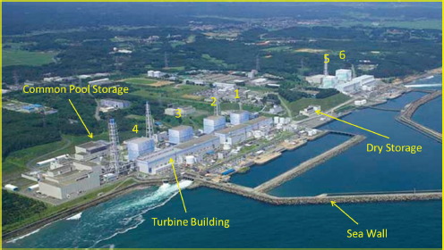
chapter is on the Unit 1-4 spent fuel pools because these units sustained severe damage as a result of the earthquake and tsunami (see NRC, 2014, Chapter 4). Summary information about spent fuel storage in Units 5 and 6, the common pool, and dry cask storage is provided in Appendix 2A.
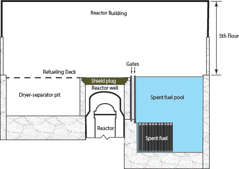
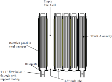
Units 1-4 at the Fukushima Daiichi plant are boiling water reactors (BWRs) with Mark I containments. Their spent fuel pools are located on the fifth-floor refueling decks in the upper portions of the reactor buildings (Figure 2.2). Each pool (right-hand side of Figure 2.2) is constructed of about 1.5-m (5-ft) thick reinforced concrete with a 5-mm (0.2-inch) thick steel liner. The pools are rectangular in horizontal dimension1 and almost 12 m deep. Fuel assemblies are stored vertically in metal racks at the bottoms of the pools (Figure 2.3). The racks are covered by about 7 m (23 ft) of water when pool water is at nominal levels. The tops of the spent fuel racks are designed to be slightly taller than the top of the active fuel. The racks in the spent fuel pools at the Fukushima Daiichi plant are about 40 cm taller than the top of the active fuel. In U.S. designs the racks are slightly taller than the top of the active fuel but the exact difference can vary by plant design. The pools contain regions without racking that are used for loading fuel transfer casks.
___________________
1 The Unit 1 pool is 12 m × 7.2 m in area; the Unit 2-4 pools are 12.2 m × 9.9 m in area.
TABLE 2.1 Spent Fuel Storage at the Fukushima Daiichi Plant on March 11, 2011
| Unit | Decay Heat (MW) | Water Volumea (m3) | Total Number of Fuel Assemblies in Poolb | Fuel Rack Occupancyc (%) | Total Radionuclide Activity of Fuel (MCi) | Cs-137 Radionuclide Activity of Fueld (MCi) |
|---|---|---|---|---|---|---|
| 1 | 0.18 | 990 | 292 (100) | 44 | 43.2 | 4.43 |
| 2 | 0.62 | 1,390 | 587 (28) | 50 | 149 | 12.1 |
| 3 | 0.54 | 1,390 | 514e (52) | 46 | 130 | 10.6 |
| 4 | 2.26 | 1,390 | 1,331 (204) | 97 | 568 | 23.9 |
| 5 | 1.01 | 1,390 | 946 (48) | 63 | 249 | — |
| 6 | 0.87 | 1,460 | 876 (64) | 53 | 73.0 | — |
| Common Pool | 1.13 | 3,828 | 6,375 | 93 | 378 | — |
| Dry Cask | N/A | 408 | N/A | |||
NOTES: MW = megawatts (106 watts); MCi = megacuries (106 curies).
a Actual pool volumes are slightly larger than the volumes reported here because of the displacement of the fuel and racks and the control of water levels below the top of the pool.
b Amounts in parentheses are new fuel assemblies that are in addition to the spent fuel amounts shown.
c Including new (unirradiated) fuel.
d For comparison, the reactor cores in Units 1, 2, and 3 had Cs-137 activities of 6.5, 6.9, and 6.5 MCi, respectively.
e There were mixed oxide fuel assemblies in the Unit 3 reactor but none in the pool.
SOURCES: Activity data from Table 2.1.1-5 of NAIIC (2012) and from estimates by Nishihara et al. (2012) as reported by Povinec et al. (2013); decay heat, water capacity, and assembly data from Attachment 9-1 of TEPCO (2012a).
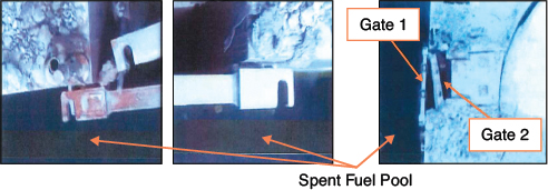
The pools are located adjacent to the reactor well, a large cavity located above the reactor pressure vessel (Figure 2.2). The well and pool are connected by a short canal that contains two gates.2 When the gates are closed, the pool and reactor well are hydraulically separated.
The reactor well is located adjacent to the dryer-separator pit (Figure 2.2). That pit is used to store reactor components (i.e., the steam separator, steam dryer, and reactor shroud) when the reactor is undergoing refueling or heavy maintenance. These radioactive components are removed
___________________
2 These gates are approximately 0.9 m (3 ft) wide and 6.4 m (20 ft) tall and have polymeric seals to prevent water leakage. The gate adjacent to the pool is sealed by the pool’s water pressure—about 17 tonnes of force when pool water is at nominal levels. See Appendix 2C, especially Figure 2C.1, for details.
from the reactor and transferred into the pit using an overhead crane that moves along steel rails on the walls of the reactor building.
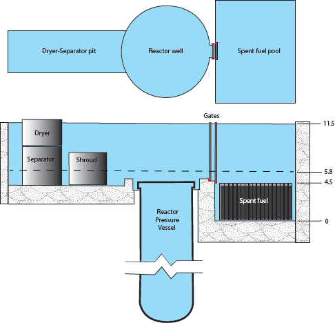
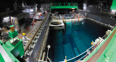
The reactor well and dryer-separator pit are flooded with water, and the gates are opened for reactor refueling and some maintenance operations (Figure 2.4). Fuel is moved underwater between the reactor and pool using a fuel handling machine that runs on rails located on the refueling floor
(Figure 2.5). Spent fuel may be moved from the pool racks into casks for transfer to the common pool prior to reactor refueling to make room in the pool for newly offloaded fuel. These casks are moved in and out of the pool using the overhead crane.
The Unit 1-3 reactors at the Fukushima Daiichi plant were in normal operation prior to the March 11, 2011, earthquake and tsunami. Their refueling decks were configured as shown in Figure 2.2. The gates separating the spent fuel pools from the reactor wells were closed, and their reactor wells and dryer-separator pits were dry.
The Unit 4 reactor was undergoing heavy maintenance on March 11, 2011. Its refueling deck was configured as shown in Figure 2.4. The shield plug and barriers shown in Figure 2.2 between the reactor well and the dryer-separator pit were removed once the reactor well was flooded, the containment vessel and reactor pressure vessel upper heads were removed to access the reactor core, and the gates between the spent fuel pool and reactor well were closed. All of the fuel in the reactor core had been offloaded to the pool. The fuel from the core had high decay heat because the reactor had been shut down only 102 days earlier (Government of Japan, 2011).
The spent fuel pools at Fukushima Daiichi Units 1-4 contained many fewer assemblies than are typically stored in spent fuel pools at U.S. nuclear plants. The storage capacity of U.S. spent fuel pools ranges from fewer than 2,000 assemblies to nearly 5,000 assemblies, with an average storage capacity of approximately 3,000 spent fuel assemblies. U.S. spent fuel pools are typically filled with spent fuel assemblies up to approximately three-quarters of their capacity (USNRC NTTF, 2011, p. 43).
The Unit 1-4 spent fuel pools are equipped with active cooling systems; in particular the Spent Fuel Pool Cooling and Cleanup (FPC) systems, which are located within the reactor buildings below the refueling decks and in a nearby radwaste building. This system is designed to maintain pool temperatures in the range 25°C to 35°C (77°F to 95°F) by pumping the pool water through heat exchangers. The system also filters the pool water and adds makeup water as necessary to maintain pool water levels. All of these features require electrical power.
The pools and refueling levels contain instruments to monitor water levels, temperatures, and air radiation levels. These measurements are displayed in the main control rooms. The temperature and water-level indicators are limited to a few locations3 near the tops of the pools for the purpose of maintaining appropriate water levels during normal operations:
- Pool water level is monitored by two level switches installed 30 mm (~0.1 ft) above and 160 mm (~0.5 ft) below the normal water level in the pool.
- Pool water temperature is monitored by a sensor 300 mm (~1 ft) below the normal water level of the pool.
This instrumentation also requires electrical power to operate and has no backup power supply.
2.2 IMPACTS OF EARTHQUAKE AND TSUNAMI ON THE UNIT 1-4 SPENT FUEL POOLS
NRC (2014) provides a discussion of key events at the Fukushima Daiichi plant following the March 11, 2011, earthquake and tsunami. To
___________________
3 The description of the instrumentation is what was available in normal operation before March 11, 2011, and is what is nominally provided in typical U.S. BWR Mark I plants. After the tsunami and explosions in Units 1, 3, and 4, the standard equipment was inoperable. In some cases, improvised instrumentation was lowered into the pools, and in other cases the water level was observed indirectly through the overflow to the surge tank and temperature was monitored at selected locations in the FPC systems. The temperature sensor in the pool of Unit 2 was operational once instrument power was restored.
summarize, Units 1-4 lost external power as a result of earthquake-related shaking. Units 1-4 also lost all internal AC power and almost all DC power for reactor cooling functions as a result of tsunami-related flooding. Efforts by plant operators to restore cooling and vent containments in time to avert core damage were unsuccessful. As a result, the Unit 1, 2, and 3 reactors sustained severe core damage and the Unit 1, 3, and 4 reactor buildings were damaged by explosions of combustible gas, primarily hydrogen generated by steam oxidation of zirconium and steel in the reactor core and, secondarily, by hydrogen and carbon monoxide generated by the interaction of the molten core with concrete.
The loss of AC and DC power and cooling functions also affected the Unit 1-4 spent fuel pools: The pools’ FPC systems, secondary cooling systems, and pool water-level and temperature instrumentation became inoperable. High radiation levels and explosion hazards prevented plant personnel from accessing the Unit 1-4 refueling decks. Consequently, no data on pool water levels or temperatures were available for almost 2 weeks after the earthquake and tsunami. Moreover, even after pool instrumentation was restored, it was of limited value because of the large swings in pool water levels that occurred during the accident.4
Improvised instrumentation and aerial observations were used to monitor pool conditions. Aerial and satellite photography were particularly important sources of information in the early stages of the accident although the images were not always interpreted correctly.
The earthquake caused the reactor buildings to sway, which likely caused water to slosh from the pools.5 No observational data on sloshing-related water losses are available, however. Analyses performed by the plant owner, TEPCO, suggest that sloshing reduced pool water levels by about 0.5 m (TEPCO, 2012a, Attachment 9-1). The sloshed water spilled onto the refueling decks and likely flowed into the reactor buildings through deck openings such as floor drains.
The explosions in the Unit 1, 3, and 4 reactor buildings likely caused additional water to be sloshed from the pools in those units. Again, no observational data on explosion-related water losses are available. Sloshing due to building motion resulting from the explosions is unlikely to be significant. But sloshing will occur if there is a spatially nonuniform pressure distribution created on the pool surface by an explosion in the region above the pool. This is particularly likely for high-speed explosions that
___________________
4 As noted previously, all of the water-level and temperature instrumentation was installed within 300 mm (~1 ft) of the top of the pools.
5 Sloshing was directly observed in the Kashiwazaki-Kariwa nuclear plant during a 2007 earthquake (NAIIC, 2012, p. 97) and reportedly resulted in a large loss of water from the spent fuel pools.
create shock or detonation waves.6 TEPCO estimates that an additional 1 m of water was sloshed from each of the pools as a result of the explosions (TEPCO, 2012a, Attachment 9-1, p. 3/9).
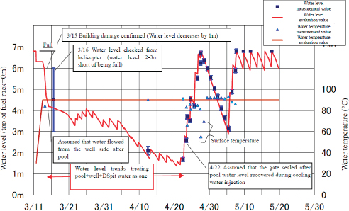
Personnel in the plant’s Emergency Response Center (see NRC, 2014, Appendix D) were focused on cooling the Unit 1-3 reactors and managing their containment pressures during the first 48 hours of the accident. They knew that restoring cooling in the spent fuel pools was less urgent and prioritized accordingly. Beginning on March 13, 2011, operators became increasingly concerned about water levels in the pools; their concerns increased following the explosions in the Unit 3 and 4 reactor buildings on March 14 and 15, respectively (Sidebar 2.1).
By the morning of March 15, 2011, it was apparent that the Unit 1-3 reactors had been damaged and were releasing radioactive material. TEPCO evacuated all but about 70 personnel from the plant because of safety concerns (personnel began returning a few hours later). That same day, TEPCO initiated a comprehensive review of efforts to cool the spent fuel pools and made it a priority to determine the status of the Unit 4 pool. TEPCO added the Unit 3 pool to its priority list on the morning of March 16 after steam7 was observed billowing from the top of the Unit 3 reactor building.
Details about key events in the Unit 1-4 spent fuel pools and operator responses are described in the following sections.
2.2.1 Unit 1 Pool
The explosion in the Unit 1 reactor building on March 12, 2011, blew out the wall panels on the fifth floor, but the steel girders that supported the panels remained intact. The roof collapsed onto the refueling deck and became draped around the crane and refueling machinery8 (Figure 2.6). This wreckage prevented visual observations of and direct access to the pool.
TEPCO estimated that the pool lost about 129 tonnes of water from the earthquake- and explosion-related sloshing. This lowered the water level in the pool to about 5.5 m above the top of the racks. Because of the very low decay heat in Unit 19 (Table 2.1), this pool was of least concern
___________________
6 For example, sloshing has been observed in laboratory experiments with shock wave loading (Teodorcyzk and Shepherd, 2012).
7 Some descriptions of the accident by TEPCO and others refer to steam emissions from the reactor buildings as “white smoke” emissions.
8 The refueling floor has been inspected visually (Figure 2.6). Although there is a great deal of rubble, the refueling machine and overhead crane appear to be intact. Rubble removal and demolition will be needed in preparation for installing fuel and cask handling equipment to transfer fuel out of the pool.
9 All of the spent fuel in the pool was at least 1 year old.
to plant operators, and in fact water was not added to the pool until the end of March 2011.
Operators initially considered several approaches for adding water to the Unit 1 pool: sending personnel into the reactor building to connect fire hoses to an FPC line, dropping ice or water from helicopters into the pool, and spraying water into the pool using a fire truck equipped with a ladder. All of these approaches were deemed to be impractical or pose unacceptable risks to plant personnel.
Operators used a concrete pump truck to add fresh water to the pool starting on March 31, 2011. Water was pumped onto the collapsed roof structure and some of it ran off into the pool. The amount of water that reached the pool was uncertain because the pool could not be observed visually.
A subsequent survey of the Unit 1 reactor building indicated that radiation levels were relatively low at the southwest corner of the third floor where the FPC pump and heat exchanger were located. Operators gained access to that area and were able to remove a check valve in the FPC piping and attach a temporary adapter for a fire hose. The fire hose was run outside the building to a temporary motor-driven pump connected to fresh-water storage tanks. Water was injected into the pool by this method after May 28, 2011.
An alternate cooling system was installed and put into operation on August 10, 2011. This system used the spent fuel pool heat exchanger and pump and a temporary air-cooled heat exchanger and closed-loop circulation system outside the building.
TEPCO estimated that the water level in the Unit 1 pool decreased by 3 m (to about 4 m above the top of the racks) by May 21, 2011: 1.5 m of this water loss was due to sloshing and another 2.2 m of water loss was
due to evaporation; credit is taken for 0.7 m (63 tonnes) of water added on March 31.
The committee estimated the evaporative water loss in the Unit 1 pool using the steady-state energy-balance model described in Appendix 2B. The main contribution of the committee’s model was to examine in detail the role of leakage through the gates between the reactor well and the spent fuel pool in Unit 4, a key issue that was identified during the course of the committee’s deliberations. The evaporative loss from Units 1, 2, and 3 was also examined but in much less detail.
The committee estimates that evaporative water losses from the Unit 1 pool between March 11 and May 21, 2011, totaled about 2.6 m, resulting in a water level about 4.4 m above the top of the racks. If TEPCO’s sloshing loss estimates are included and no credit is given for water additions by the concrete pump truck, then water levels could have been as low as 2.9 m above the top of the racks.10
2.2.2 Unit 2 Pool
There was no explosion in the Unit 2 reactor building, but a blowout panel on the east side of the refueling deck became dislodged after the Unit 1 explosion on March 12, 2011. Steam was occasionally observed to emerge from this opening. Its origin is unclear, but it may have originated from the interior of the reactor building rather than from the spent fuel pool. There has been no evaluation of how this opening affected the evaporation rate from the pool.11
Operators focused their efforts on using components of the installed FPC system to inject water into the pool. The initial idea was to inject water through the Make-Up Water Condensate system line. However, this would require the replacement of a power panel and pump inside the contaminated turbine building where radiation levels were deemed too high to work.
Instead, plant personnel removed a sight glass from the FPC line in the radioactive waste building and connected a fire hose. Seawater from the north quay was pumped through this hose using a fire truck (and later a motor-driven pump).
Seawater was injected into the pool starting on March 20, 2011, and continued intermittently thereafter. The water supply was switched to
___________________
10 This water-level estimate is consistent with TEPCO’s estimate with no credit given for water injection on March 31, 2011 (TEPCO, 2012a, Attachment 9-2).
11 Simulations using Methods for Estimation of Leakages and Consequences of Releases (MELCOR; Gauntt et al., 2012) predict that the net evaporation rate is reduced by a factor of 2 when a pool is enclosed in an intact building relative to when there is no enclosure. (Evaporated water condenses on the building and structures with some fraction flowing back into the pool.) Gauntt et al. did not simulate the effect of partial building venting.
fresh water on March 29 and pumping at regular intervals continued until May 31. At that time cooling was switched over to an alternate cooling system that used the FPC lines but with a new primary heat exchanger and pump in the radioactive waste building and a new secondary cooling system with a cooling tower outside the building. Between 40 and 60 tonnes of water were injected into the pool every 3 days until the end of May 2011.
TEPCO estimates that water levels in the pool had dropped to about 5.5 m above the top of the racks by the end of March 2011. However, there are no measurements of actual pool levels. According to the committee’s steady-state energy-balance model (Appendix 2B), pool levels would have decreased by about 0.16 m/day due to evaporation, which is consistent with the observed temperature records12 from TEPCO (TEPCO, 2012a, Attachment 9-3, pp. 7/8-8/8).
Measured water temperatures in the pool fluctuated between 50°C and 70°C with the periodic addition of water to maintain pool levels. The temperature fluctuations were likely caused by changes in pool water levels: When the pool was full, the temperature sensor was submerged and indicated the water temperature; when the water level dropped, the sensor was exposed and indicated the air-vapor temperature near the top of the pool.
2.2.3 Unit 3 Pool
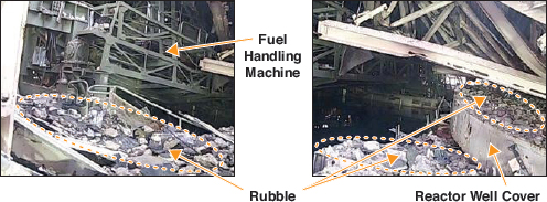
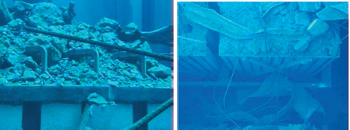
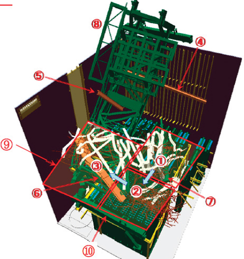
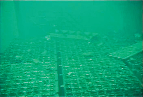
The explosion in the Unit 3 reactor building on March 14, 2011, damaged the northwest side of the fifth floor, collapsing the steel and concrete structure. Steel framing and concrete members were collapsed on top of each other on the fourth floor, and substantial portions of the walls of the fourth floor were also damaged.13 The explosion introduced a substantial amount of debris, building structural components, and equipment (including the fuel handling machine) into the spent fuel pool. These materials are resting on the bottom of the pool and on the top of the racks (Figures 2.7 and 2.8).14
Steam was observed billowing from the top of Unit 3 on the morning of March 16, 2011. This steam, combined with the extensive destruction of the fourth and fifth floors, suggested to some observers that the pool was damaged or low on water and the spent fuel was undergoing rapid steam oxidation (see Sidebar 2.2).
___________________
12 As noted previously, the temperature gauge is located 300 mm (1 ft) below the top of the normal water level in the pool. Temperature readings indicate that the gauge was uncovered in 1-2 days, indicating that pool water level decreased by about 0.2 m per day.
13 Radioactive contamination in the building has prevented the onsite assessment of the integrity of the structure under the pool.
14 Debris has been cleared from the refueling deck, and work is now in progress to clear debris from the pool to assess the condition of the fuel and racks. TEPCO announced on August 2, 2015, that it had removed the spent fuel handling machine from the pool. See http://www.tepco.co.jp/en/press/corp-com/release/2015/1256671_6844.html.
A TEPCO-arranged helicopter flight over the Fukushima Daiichi site on the afternoon of March 16, 2011, obtained additional information about conditions in the pools. Debris and billowing steam obscured the Unit 3 pool, so little visual information could be obtained about its condition. A later analysis15 of aerial photographs and thermal imaging was undertaken by the Nuclear Regulation Authority (NRA, 2014) to pinpoint the origin of the steam: It was found to originate from near the reactor well cover and the dryer-separator pit, not the spent fuel pool. Thermal imaging on March 20, 2011, showed that the pool water temperature was about 60°C, whereas temperatures adjacent to the reactor cover and dryer-separator pit measured by thermal imaging were over 100°C. (Building debris obscured the exact source of the steam plume.) The steam may have been generated in the reactor pressure vessel or containment.
Operators made several efforts to add water to the Unit 3 spent fuel pool following the helicopter overflight. From March 17 to March 25, 2011, operators attempted to add water using helicopters and fire trucks. The helicopter water drops were unsuccessful, and the fire truck sprays were ineffective. On March 23 and 24, an attempt was made to inject sea water through an improvised connection to the FPC system. This also was ineffective, apparently because the lines were clogged. From March 27 to April 22, operators added water using a concrete pump truck. The strainer in an FPC line was subsequently removed, and water was successfully injected into the pool beginning on April 26 and continuing until an
___________________
15 This analysis was undertaken to clear up questions that had been raised in the July 2012 Diet report on the accident (NAIIC, 2012).
alternate cooling system similar to that used in Unit 2 (i.e., connecting a fire hose to the FPC system in the radwaste building and pumping seawater using a fire truck) was established on June 30.
The committee’s steady-state energy-balance model (Appendix 2B) estimates that pool levels dropped by about 2.5 m between March 11 and April 2, 2011, lowering the water level in the pool to about 4.5 m above the top of the racks. If TEPCO’s sloshing losses are included, then water levels could have been as low as 3.0 m above the top of the racks if no
credit is given for the water added by the concrete pump truck beginning on March 27, 2011.
Recent visual inspections of the pool reveal that one of the spent fuel pool gates has been displaced (see Figure 2.9) from its normal position and appears to be deformed. It is not clear whether this displacement was caused by the earthquake, the explosion, or debris falls.
2.2.4 Unit 4 Pool
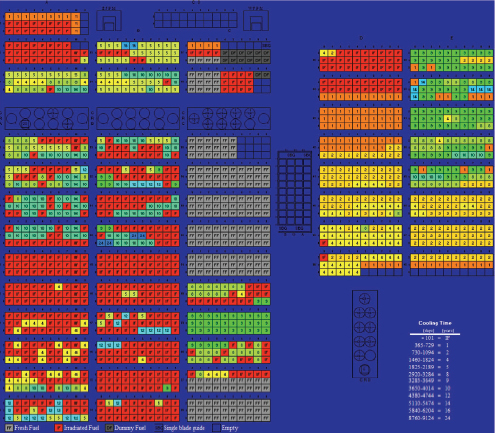
The Unit 4 reactor was shut down for maintenance, and large-scale repairs were in progress (see NRC, 2014, Chapter 4) on March 11, 2011. The configuration of the Unit 4 refueling deck is illustrated in Figure 2.4: The reactor well and dryer-separator pit had been flooded with water, internal reactor components (steam separator, steam dryer, and reactor shroud) had been removed from the reactor and placed in the pit, and the reactor core comprising 548 fuel assemblies had been removed from the reactor and placed into contiguous racks in the spent fuel pool (Figure 2.10). The gates16 separating the reactor well from the spent fuel pool were closed.
The explosion that occurred in the Unit 4 reactor building at 06:14 on March 15, 2011, destroyed the roof and most of the walls on the fourth and fifth (refueling deck) floors, and it damaged some of the walls on the third floor. TEPCO (2012a) has suggested that the explosion was due to the com-
___________________
16 The configuration for the two gates shown for Unit 3 (Figure 2.9) appear to be similar to the configuration in Unit 4 according to TEPCO (2012a, Figure 3 of Attachment 9-5); see Figure 2C.1 in Appendix A.
bustion of hydrogen that was generated in Unit 3 and flowed into Unit 4 through the ventilation system.17 The fifth-floor slab was pushed upward and the fourth-floor slab was depressed.18 The explosion also deposited
___________________
17 As mentioned previously, carbon monoxide from core-concrete interaction in Unit 3 is another potential source for combustible gas that could have fueled the explosion in Unit 4.
18 Plant operators were concerned about the integrity of the building structure underneath the Unit 4 pool following the explosion. The building was surveyed, concrete was tested, and the building response to an earthquake was simulated as part of the assessment of the structure. In June 2011, the region underneath the pool was reinforced with steel beams and filled with concrete; this work was completed on July 30, 2011. Quarterly inspections have been carried out since May 2012 and no significant issues have been found. The Unit 4 pool’s inventory of 1,535 fuel assemblies was moved into the common pool (spent fuel) or Unit 6 pool (new fuel) between November 2013 and December 2014.
debris around the reactor building, onto the refueling deck, and into the pool (Figure 2.11). Fires were reported in the damaged building later that morning and on the morning of March 16; these fires self-extinguished and were later attributed to the ignition of lubricating oil.
The damage to the Unit 3 and 4 building structures and steam emissions from both buildings raised grave concerns about the spent fuel pools in those units (see Sidebars 2.1 and 2.3). Unit 4 was of particular concern because the reactor contained no fuel and therefore could not have been the source of hydrogen or other combustible gas. The only apparent source of combustible gas within Unit 4 was hydrogen from the steam oxidation of spent fuel in the fully or partially drained Unit 4 spent fuel pool (Sidebar 2.4).
Plant operators well understood the hazard posed by the spent fuel in the Unit 4 pool: The pool was loaded with high-decay-heat fuel; its water level was dropping because of large evaporative water losses; and openings in the Unit 4 building created by the explosion created pathways for radioactive materials releases into the environment. Operators communicated this understanding to TEPCO headquarters and to government agencies. However, there were disagreements between TEPCO and regulators about the status of the Unit 4 pool:
“. . . NISA [Nuclear and Industrial Safety Agency of Japan] and the [US] NRC both insisted that the water level in the Unit 4 SFP [spent fuel pool] had dropped and the fuel was exposed, but TEPCO insisted that the fuel was not exposed because as of 15:00 [on March 15] when the explosion at the Unit 4 reactor building occurred, not enough heat was being generated to cause the fuel to be exposed, and surrounding radiation levels were too low to indicate that the fuel was exposed.” (TEPCO, 2012a, p. 297)
According to TEPCO, visual observations and a video recording made during the March 16, 2011, helicopter overflight (see Sidebar 2.1) showed that the Unit 4 pool contained water above the top of the fuel racks. However, TEPCO was unable to draw a similar conclusion about water levels in the Unit 3 pool because it was obscured by debris. Consequently, plant operators shifted their attention to the Unit 3 pool from March 16 to March 20.
The extensive visible damage to the Unit 4 reactor building and high level of decay heat in the Unit 4 pool continued to drive concerns about pool water levels. Operators began to add water to the Unit 4 pool starting on March 20, 2011. They first attempted to add water to the pool using water cannons and fire truck sprays on March 20 and March 22, respectively. These methods had limited effectiveness.19 Operators then used a concrete pump truck to add water starting on March 22. In general, the effectiveness of this approach increased with time as personnel gained experience in remote operation of the truck.
TEPCO began systematic water-level measurements after April 12, 2011, and had refilled the pool by April 28. TEPCO then deliberately stopped adding water to the pool until May 6 but continued to measure the water level every day. The measurements were compared with energy-balance computations to determine whether water was leaking out of the pool, through either the gate seal or the pool liner. No leaks were detected.
Operators explored other approaches for adding water to the Unit 4 pool. They considered placing a pump on the refueling deck to transfer water from the reactor well and dryer-separator pit (with a combined volume of about 1,500 m3) to the pool. This idea was dismissed because of concerns about personnel safety. They also considered using the FPC system, but aerial photography indicated that the check valve had been damaged by the building explosion.
The concrete pump truck was replaced with two other temporary measures in June 2011: The first was a fire hose run up the side of the building from a pump attached to a filtered water tank. The hose nozzle was attached to the fuel handling machine and directed downward into
___________________
19 See discussion in Chapter 7 of Gauntt et al. (2012) and TEPCO (2012a, Attachment 9-1).
the pool. The second was injection through the in-core neutron monitoring tubes at the bottom of the reactor to refill the reactor well and dryer-separator pit. These temporary measures were replaced after July 30 by the same system used to cool the Unit 2 and 3 pools.
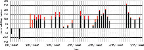
TEPCO’s estimates of water additions to the Unit 4 pool between March 11 and May 12, 2011, are shown in Figure 2.12. The black bars in the figure represent TEPCO’s best-estimate water additions; the origin of these estimates is unclear.20 The black bars plus red bars represent TEPCO’s maximum-estimate additions; these were determined by measuring actual flow rates and flow durations. The “uncertainty” in water additions, represented by the red bars, is 940 tonnes, or 940 m3 of water at standard pressure and temperature. This is approximately two-thirds the volume of the Unit 4 pool (see Table 2.1).
TEPCO used a mass- and energy-balance model to estimate water levels and temperatures in the Unit 4 spent fuel pool between March 11 and May 30, 2011. The results are shown in Figure 2.13. TEPCO speculates (TEPCO, 2012a, Attachments 9-1 and 9-5) that as water levels in the pool dropped because of evaporation, forces on the gates from water in the reactor well caused leakage around the gate seals, allowing additional water to enter the pool. This process is depicted in Figure 2.14. TEPCO also speculates that water leaked from the reactor well and dryer-separator pit into
___________________
20 The committee could find no technical documentation for these estimates and presumes that they are based on engineering judgment.
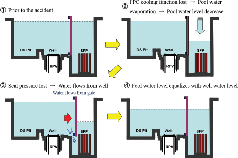
the pool until April 22, 2011, when the gates were known to be secured. TEPCO estimates that water levels in the Unit 4 pool never declined below 1.5 m above the top of the fuel rack (Tateiwa, 2015) because of these water additions.
2.2.5 Damage to Spent Fuel in Units 1-4
There were significant concerns by TEPCO that the stored spent fuel in Units 1-4 may have been damaged by the earthquake and/or the explosion on March 15. TEPCO analyzed water samples obtained from the pools to determine whether radioactive contamination from damaged fuel was present. Measured activities and isotopic compositions are consistent with fallout from reactor core releases, with the possible exception of contributions from a small number of damaged spent fuel rods in Unit 2 (Jäckel, 2015). Evaluation of the potential contribution from damaged spent fuel is highly uncertain due to the masking effect of contamination due to fallout. Visual inspection of the fuel assemblies removed from the Unit 4 pool did not reveal any damage.
2.3 COMMITTEE ANALYSIS OF UNIT 4 POOL WATER LEVELS
TEPCO did not provide enough technical documentation for its water-level estimates in the Unit 4 spent fuel pool (Figure 2.13) to enable the committee to evaluate whether those estimates are realistic. In particular, there was insufficient information about the methods used to estimate water leakage around the gate seals and the total volume of leakage to the pool. These leakage estimates are critically important for obtaining realistic estimates of pool water levels.
The committee developed its own estimates of water levels in the Unit 4 pool between March 11 and May 12, 2011, to compare to the TEPCO estimates (Figure 2.13). The mathematical model and limitations are described in Appendix 2B, and the key features are as follows:
- Evaporative water losses from the pool, which are driven by thermal heating of the pool water from radioactive decay in the stored spent fuel, were estimated using the steady-state energy-balance model described in Appendix 2B. Pool water level and temperature were assumed to be nominal (7 m above the fuel racks and 30°C, respectively) just prior to the March 11, 2011, earthquake and tsunami.
- Water losses from the pool from sloshing were assumed to be 0.5 m for the March 11, 2011, earthquake and 1 m for the March 15 explosion, identical to TEPCO’s estimates.
- Water additions to the pool from external sources were assumed to be equal to TEPCO’s best-estimate additions shown by the black bars in Figure 2.12.
- Water additions to the pool from leakage around the gate seals were estimated using the orifice flow-rate correlation described in Appendix 2C. Water was assumed to flow in one direction from the reactor well to the spent fuel pool and only if the reactor water level was higher than the pool level; see Appendix 2C for further discussion of this issue.
The committee’s estimates for the Unit 4 pool and reactor well and dryer-separator pit water levels are indicated by the blue and orange curves, respectively, in Figure 2.15. Note the following features in the committee’s estimates:
- The vertical drop in water levels in the pool and reactor well and dryer-separator pit on March 11, 2011, was the result of earthquake-driven water sloshing as estimated by TEPCO.
- Following the earthquake, evaporative losses of water from the pool remained low until the pool temperature reached equilibrium,21 at which point heat gained in the water from radioactive decay in the stored spent fuel balanced heat lost from water evaporation. The increase in pool-water evaporation rates is indicated by the change in the slope of the pool water-level curve starting around March 13, 2011.
- The explosion on March 15, 2011, caused an additional 1 m of water to slosh from the pool and reactor well and dryer-separator pit according to TEPCO.
- The model predicts that water began to leak from the reactor well into the pool on March 16, 2011. This leakage is indicated by the decrease in slope of the pool water-level curve (blue curve) and increase in slope of the reactor well and dryer-separator pit water-level curve (orange curve). Pool water levels are predicted to drop to within about 3.5 m above the top of active fuel22 on March 22, 2011. Subsequently, the combination of water leakage around the gates and external water additions (Figure 2.12) was sufficient to maintain pool water levels above the top of the fuel.
___________________
21 As shown in Table 2B.1 in Appendix 2B, equilibrium temperature in the Unit 4 pool is estimated to be 88°C, reached about 1.9 days after the FPC system shut down.
22 TAF is 0.4 m below the top of the fuel racks.
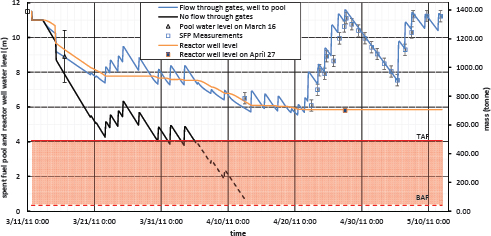
- Pool water levels dropped to less than 2 m above the tops of the racks on April 13 and again on April 20, 2011.23 The water-level drop between April 4 and April 12 was a consequence of insufficient water injection amounts because TEPCO evaluated the need for additional water based on unreliable instrumentation for measuring water levels in the pool. Operators used a water-level indicator in the skimmer surge tank to determine whether the pool was full. They subsequently realized (TEPCO, 2012a, Attachment 9-5) that water oversprays onto the refueling deck were entering the skimmer surge tank through floor drains, bypassing the pool altogether, so less water was being added to the pool than estimated.24
- Leakage of water from the reactor well into the pool continued until April 21, 2011, when TEPCO was able to maintain sufficient
___________________
23 TEPCO calculated a minimum height of 1.5 m above the top of the rack on April 20 (Tateiwa, 2015).
24 After April 12, 2011, TEPCO was able to make direct visual observations of water injection using boom-mounted video cameras.
water levels in the pool to keep the gates sealed. The committee estimates that between about 650 and 710 tonnes of water leaked from the reactor well into the pool between March 16 and April 21, equivalent to about half the volume of the pool.
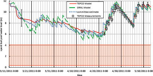
Figure 2.16 compares the present committee’s water-level estimates (blue curve in Figure 2.15) with water-level estimates from Oak Ridge National Laboratory (ORNL) (Wang et al., 2012) and water-level estimates and measurements from TEPCO (Figure 2.13). After April 22, 2011, there is good agreement among all of the water-level estimates and TEPCO’s water-level measurements. This is consistent with water no longer leaking around the gate seals.
Prior to April 22, 2011, all of the water-level estimates have similar trends (Figure 2.16). However, the ORNL and committee estimates indicate that the pool experienced larger water-level excursions and lower absolute water levels compared with the TEPCO estimates. The ORNL and committee estimates indicate that water levels ranged between 1 and 2 m above the top of active fuel between April 10 and 22; TEPCO estimates that water levels never fell below 2 m above the top of active fuel. These differences are apparently due to TEPCO’s assumption that the reactor well and spent fuel pool were “hydraulically connected” before April 22. This connection effectively doubles the mass of water available to absorb heat from the spent fuel and reduces changes in pool water levels.
There are substantial uncertainties due to the simplified assumptions used in the model for the committee’s water-level estimates between March 11 and April 20, 2011, because
- Water losses from earthquake- and explosion-related sloshing were not measured. The estimates were likely based on engineering judgment.
- The committee’s estimates for water leakage from the reactor well and dryer-separator pit to the pool prior to April 20, 2011—between about 650 and 710 tonnes—are based on an engineering model for gate leakage that has large uncertainties in the parameters.
- TEPCO’s effectiveness estimates for water additions to the pool (Figure 2.12) also appear to be based on engineering judgment and are subject to significant uncertainty: at least 940 tonnes, the sum of the red bars in Figure 2.12.
- Pool water levels prior to April 12, 2011, were not measured. As noted previously, the water-level indicator in the skimmer surge tank provided misleading information on pool water levels prior to this date.
- The committee’s steady-state energy-balance model does not account for the presence of fuel or racks other than through the decay heat of the spent fuel. A number of effects not accounted for in the model become important once the water level drops below the top of the racks, most notably the reduction in cross-sectional water area. Consequently, the water-level estimate without gate leakage shown in Figure 2.15 is indicated by a dashed line once it falls below top of the racks after April 5. This estimate is increasingly unreliable below this level because of geometrical inaccuracy and also because of other physical phenomena not accounted for by the model, including rack and fuel heat capacity, multiphase flow, film boiling, cladding oxidation, flow blockage, and change in geometry with loss of cladding integrity. Computations that include many of these effects are discussed in the Sandia analysis of a hypothetical loss-of-cooling accident in Unit 4 (see Chapter 8 of Gauntt et al., 2012).
Two important observations can be made from the committee’s analysis of water levels in the Unit 4 pool. First, because of the substantial uncertainties cited above, the committee cannot rule out the possibility that spent fuel in the Unit 4 pool became partially uncovered sometime prior to April 21, 2011. If the fuel was uncovered, however, then it was not substantial enough to cause fuel damage or substantially increase external dose rates in areas
TABLE 2.2 Estimated Peak Radiation Dose on the Refueling Deck Next to a Pool with Recently Offloaded Spent Fuel as a Function of Pool Water Level
| Height of Water Level above Racks (m) | Peak Dose Rate on the Refueling Deck | |||||
|---|---|---|---|---|---|---|
| 0.0 | 450-600 rem/hr | |||||
| 0.6 | >25 rem/hr | |||||
| 1.0 | 1.6-1.7 rem/hr | |||||
| 3.0 | < 0.1 mrem/hr | |||||
SOURCE: USNRC (2014a, pp. 88-89).
around the Unit 4 building. Fuel damage will not begin immediately when the water level drops below the top of the rack. Simulations of loss-of-cooling accidents (Gauntt et al., 2012) predict that it is possible to recover without fuel damage as long as the collapsed25 water level does not drop below the midheight of the fuel for an extended period of time.
Second, leakage through the gate seals was essential for keeping the fuel in the Unit 4 pool covered with water. Had there been no water in the reactor well, there could well have been severe damage to the stored fuel and substantial releases of radioactive material to the environment. This is the “worst-case scenario” envisioned by then–Atomic Energy Commission of Japan Chairman Dr. Shunsuke Kondo (see Sidebar 2.3).
To illustrate this second observation, the committee modeled a hypothetical scenario in which there is no water leakage into the Unit 4 pool from the reactor well and dryer-separator pit. The results are shown by the black curve in Figure 2.15. Without water leakage, pool water levels could have dropped well below the top of active fuel (located 4 m above the bottom of the pool) in early April 2011.
In the committee’s judgment, the events in the Unit 4 pool should serve as a wake-up call to nuclear plant operators and regulators about the critical importance of having robust and redundant means to measure, maintain, and, when necessary, restore pool cooling.
The events in the Unit 4 pool also have important implications for accident response actions. As water levels decrease below about 1 m above the top of the fuel racks, radiation levels on the refueling deck and surrounding areas will increase substantially, limiting personnel access (Table 2.2). Moreover, once water levels reach approximately 50 percent of the fuel
___________________
25 Collapsed water level refers to a computed height of liquid water that has the same mass as the multiphase mixture (liquid, gas, and vapor) of water that is covering the fuel.
assembly height, the tops of the rods will begin to degrade, changing the fuel geometry and increasing the potential for large radioactive material releases into the environment (Gauntt et al., 2012, p. 183).
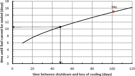
These observations bear directly on the safety of pool storage following large offloads of fuel from reactors. To illustrate this point, consider what might have occurred in the Unit 4 spent fuel pool had the reactor been shut down and the core been offloaded to the pool about 2 months later (i.e., 48 days before March 11) than it was (i.e., 102 days) and had there been no water leakage from the reactor well and dryer-separator pit. The committee estimates that pool water levels would have reached 50 percent of fuel assembly height (Figure 2.17) before 10.6 days had elapsed—which was the time elapsed between the onset of the accident on March 11 and the first addition of water to the pool in Unit 4. In this hypothetical situation, if the core had been offloaded closer to the time of the accident or if the water addition had been delayed longer than 10.6 days, then there
could have been damage to the fuel with the potential for a large release of radioactive material from the pool, particularly because the most recently offloaded (and highest-power) fuel was not dispersed in the pool but was concentrated in adjacent locations within the racks (see Figure 2.10).
2.4 FINDING AND RECOMMENDATION
FINDING 2.1: The spent fuel storage facilities (pools and dry casks) at the Fukushima Daiichi plant maintained their containment functions during and after the March 11, 2011, earthquake and tsunami. However, explosions in the Unit 1, 3, and 4 reactor buildings damaged spent fuel handling facilities and equipment, introduced heavy debris into the pools, and provided enhanced pathways for releases of radioactive materials from the damaged reactors into the environment. These events hindered efforts by plant operators to monitor conditions in the pools and restore critical pool-cooling functions. The lack of reliable real-time information about the pools created substantial difficulties in responding to the accident and led to increased public anxiety. Nevertheless, plant personnel were able to improvise and provide needed cooling to avoid pool uncovery and potential radiological consequences. The leakage of water into the Unit 4 pool from the reactor well/dryer-separator pit was a key factor for determining its water level and may have prevented fuel uncovery before plant personnel were able to add water.
RECOMMENDATION 2.1: The U.S. nuclear industry and its regulator should give additional attention to improving the ability of plant operators to measure real-time conditions in spent fuel pools and maintain adequate cooling of stored spent fuel during severe accidents and terrorist attacks. These improvements should go beyond the current post-Fukushima response to include hardened and redundant (1) physical surveillance systems (e.g., cameras), (2) radiation monitors, (3) pool temperature monitors, (4) pool water-level monitors, and (5) means to deliver pool makeup water or sprays even when physical access to the pools is limited by facility damage or high radiation levels.
2.4.1 Discussion
The spent fuel pools in Units 1-4 were sufficiently robust to survive the earthquake and explosions, although the support structure beneath the Unit 4 pool needed to be strengthened. However, the spent fuel pool gates in Unit 3 were damaged during the accident and the pool gates in Unit 4 appear to have leaked water. Although debris entered the pools and covered
portions of the racks supporting the fuel assemblies in Unit 3, the fuel does not appear to have been damaged with the possible exception of a small number of fuel rods in the Unit 2 pool.
Plant operators had not planned for or trained to respond to the conditions that existed in the Unit 1-4 spent fuel pools following the March 11, 2011, earthquake and tsunami:
- Primary and backup pool cooling systems had failed because of the loss of all power. There were no plans or equipment available for adding emergency makeup water or implementing alternate cooling strategies.
- Water-level and temperature monitoring instrumentation had also failed because of the loss of power. The limited range of monitoring instrumentation greatly reduced its effectiveness even after power was restored.
- Explosions in Units 1, 3, and 4 damaged the reactor buildings, introduced debris onto the refueling decks and into the spent fuel pools, and hindered visual observations of pool conditions.
- Radiological conditions hindered access to areas around the buildings and limited personnel access to the refueling decks and pools.
Operators successfully developed and deployed improvised means to monitor and cool the pools using helicopters, fire trucks, water cannons, concrete pump trucks, and ad hoc connections to installed cooling systems. These operator actions were clearly essential for preventing damage to the stored spent fuel and release of radioactive materials to the environment.
The committee’s Recommendation 2.1 calls on the U.S. nuclear industry and its regulator to improve the ability of plant operators to monitor real-time conditions in spent fuel pools and maintain adequate cooling of stored spent fuel during severe accidents or terrorist attacks. The recommended improvements in plant monitoring systems include the following:
- Remote surveillance of pools and refueling decks,
- Radiation levels on the refueling deck,
- Pool temperatures, and
- Pool water levels.
The lack of reliable information on pool water levels and temperatures at the Fukushima Daiichi plant created unnecessary anxiety about the condition of the stored spent fuel and may have also created false priorities for allocating resources. Reliable and hardened instrumentation is just as necessary for the spent fuel pools as it is for the reactor safety systems.
Some of the committee-recommended improvements in NRC (2014) are already being made by the U.S. Nuclear Regulatory Commission (USNRC) and nuclear industry. The USNRC required its licensees to upgrade water-level instrumentation in their spent fuel pools following the Fukushima accident.26 The regulatory guidance is to provide two independent instrumentation systems, primary and backup, with at least a 1-ft (0.3-m) resolution down to 10 ft (3 m) above the top of the racks and 3.5-ft (1-m) resolution from the 10-ft (3-m) level to the top of the racks. The systems must be powered from independent power sources and have provisions for attaching power sources independent of plant AC and DC power distribution systems, for example, portable generators or batteries. The systems must be seismically rugged, must be operable under severe accident conditions,27 and must be installed so that they have reasonable protection in case of damage to the structure over the pool. They must also be designed so that spent fuel pool water levels can be read from the control room, an alternate shutdown panel, or other accessible locations.
It is essential to have the capability to monitor water-level trends in the pool when they are within 3 m of the top of the fuel racks. This monitoring capability is needed to ensure that water additions are effective and that water levels are adequate to shield radiation from the stored spent fuel. Radiation monitors available on the refueling deck could serve as a proxy measure of water levels when they are close to the top of the fuel racks (see Table 2.2). However, these monitors may not be operable during a severe accident, and their readings may be difficult to interpret if the refueling deck is contaminated with radioactive material.
Some of the committee-recommended improvements have not been made by the USNRC or nuclear industry. In particular, the USNRC has not required plant licensees to install pool temperature monitors. In the committee’s judgment, pool temperature measurements are essential in an accident to evaluate independently whether drops in pool water levels are due to evaporation or leakage.28 As noted in Chapter 5 of the committee’s phase 1 report (NRC, 2014), the Advisory Committee on Reactor Safeguards (ACRS, 2012a, p. 5) has also recommended the installation of pool-temperature monitoring instrumentation that would display directly in the main control room. ACRS (2012b) also recommended that higher water-level spatial resolution as well as temperature measurements were needed to enable operators to respond in a timely and appropriate fashion to spent fuel pool accidents.
___________________
26 The specifications are given in USNRC guidance JLD-ISG-2012-03.
27 This water-level instrumentation must survive down to TAF.
28 Like the water-level instrumentation described previously, the temperature instrumentation must have independent power, be seismically rugged, and operate under severe accident conditions.
The committee discussed pool-water temperature monitoring in its phase 1 report (see NRC, 2014, pp. 162-163) and recommended a systematic evaluation be undertaken to determine if such monitoring was needed at U.S. nuclear plants. The committee commented that once this evaluation was completed,
“nuclear plant licensees and the USNRC might conclude that additional temperature sensors should be placed in pools to provide confirmatory information about the thermodynamic state of water inventories.”
The committee again encourages the U.S. nuclear industry and the USNRC to complete this evaluation expeditiously.
The U.S. nuclear industry is already making good progress in improving the ability of plant operators to maintain adequate cooling of stored spent fuel during severe accidents or terrorist attacks:
- Under its B.5.b initiative,29 the industry has pre-positioned equipment and developed procedures to add makeup water to spent fuel pools and cool the stored fuel assemblies with water sprays (see Chapter 3).
- Under its Diverse and Flexible Coping Strategies (FLEX) initiative30 (NEI, 2012), the industry has pre-positioned equipment and developed procedures to provide water and power to address the USNRC’s Mitigation Strategies Order (USNRC, 2012a).
- Both of these initiatives were discussed in the committee’s phase 1 report (NRC, 2014, see especially Appendixes F and G).
These initiatives may employ separate sets of equipment and procedures.31
- The industry’s FLEX strategy (NEI, 2012, p. 11) specifies that “FLEX mitigation equipment should be stored in a location or locations such that it is reasonably protected such that no one external event can reasonably fail the site FLEX capability. Reasonable protection can be provided for example, through provision of multiple sets of portable on-site equipment stored in diverse locations or
___________________
29 Codified in 10 CFR 50.54(hh)(2) for responding to large fires and explosions. These requirements are discussed in the committee’s phase 1 report (NRC, 2014). See especially Appendix G.
30 This initiative is also discussed in the committee’s phase 1 report (NRC, 2014). See especially Appendix F.
31 The FLEX strategy allows for the use of B.5.b equipment if it meets applicable FLEX requirements (NEI, 2012, p. 53).
-
through storage in structures designed to reasonably protect from applicable external events” (NEI, 2012, p. 11).
- B.5.b equipment, on the other hand, may not be protected from the kinds of external events for which FLEX equipment is designed to mitigate. Consequently, it might not be readily accessible to plant personnel during an external event that limited physical access to the pools. Moreover, this equipment is not necessarily compatible with the FLEX equipment.
Better coordination and integration of the B.5.b and FLEX equipment and procedures could enhance plant operators’ ability to respond to severe accidents and terrorist attacks. It could also provide cost savings and efficiency improvements.
The capabilities provided by B.5.b and FLEX provide for spent fuel pool mitigation strategies of 200-gpm (gallon per minute) water spray and 500-gpm makeup water for at least 12 hours. These are the types of capability that had to be improvised at Fukushima Daiichi using fire engines and concrete pump trucks. The spray solution of FLEX32 anticipates the use of hoses on the refueling deck; this is problematic if the decks are severely damaged or contaminated. Solutions that avoid these problems include the concrete pump trucks employed at the Fukushima Daiichi plant or pre-positioned nozzles (protected from falling debris) that can be remotely operated using water connections external to the spent fuel enclosure or reactor building.
Finally, the damage observed in the Unit 3 gates (Figure 2.9) demonstrates a pathway by which a severe accident could compromise spent fuel pool storage safety: drainage of water from a spent fuel pool through a damaged gate breach into an empty volume such as a dry reactor well or fuel transfer canal. A gate breach could drain a spent fuel pool to just above the level of the racks in a matter of hours, and the resulting high radiation fields on the refueling deck (Table 2.2) could hinder operator response actions. The committee judges that an effort is needed to assess the containment performance of spent fuel pool gates under severe accident conditions during all phases of the operating cycle.33 Such an assessment could be
___________________
32 USNRC (2016) notes that the FLEX portable spray capability (utilizing portable spray nozzles from the refueling floor with portable pumps) is not required when a pool is located below grade or when a seismic hazard analysis shows that the pool will maintain its integrity.
33 Assessment of spent fuel pool performance, including gate leakage, is not a new topic for the USNRC. A review of historical data in 1997 (USNRC, 1997c) documented numerous instances of significant accidental drainage of pools in pressurized water reactor and BWR plants due to various failures including gate seals. The report recommended that “[t]he overall conclusions are that the typical plant may need improvements in SFP [spent fuel pool] instrumentation, operator procedures and training, and configuration control” (p. xi). Furthermore,
carried out as part of the committee-recommended risk assessment in its phase 1 report (NRC, 2014) and in the risk assessments recommended in Chapters 4 and 5 of this report.
___________________
the report goes on to identify the most prevalent reason for loss of pool inventory was leaking fuel pool gates. Given the potential for gate leakage under normal operations it is not surprising that it is also an issue under severe accident conditions.
APPENDIX 2A
Spent Fuel Storage in Units 5 and 6, the Common Pool,
and Dry Cask Storage at the Fukushima Daiichi Plant
This appendix provides information about spent fuel storage in Units 5 and 6, the common pool, and dry cask storage at the Fukushima Daiichi plant. Table 2.1 in the main body of the chapter provides information about spent fuel storage quantities.
2A.1 UNITS 5 AND 6
The Unit 5 pool lost cooling after AC power and pumps for circulating seawater to the heat exchanges were knocked out by the tsunami. The pool temperature reached about 69°C on March 18, 2011, when improvised sea water pumps were put into operation. The residual heat removal system was used to alternately cool the reactor and the pool, during which time pool temperatures fluctuated between 30°C and 50°C. After June 25, normal cooling was reestablished with the FPC system, allowing pool temperatures to be maintained at around 30°C.
Seawater pumps were also lost in Unit 6 after the earthquake and tsunami. However, one of the emergency diesel generators continued to function. The pool temperature reached a maximum of about 68°C before the sea water pumps were restored on March 19, 2011. The residual heat removal system was used to alternately cool the reactor and the pool, during which time pool temperatures fluctuated between 20°C and 40°C.
2A.2 COMMON SPENT FUEL POOL
The earthquake and tsunami knocked out power for the FPC system, causing pool water temperatures to rise to about 73°C before the power was restored on March 24 (TEPCO, 2012a, p. 300).
2A.3 CASK STORAGE
Casks have been in use at the Fukushima Daiichi plant since 1995. The casks are steel, equipped with an inner and outer bolted closures that can be removed for inspection, and bolted to the foundation of the cask storage building, which is located at a low elevation close to the quay (see Figure 2.1). Nine casks containing a total of 408 fuel assemblies were in storage on March 11, 2011 (TEPCO, 2012a, Attachment 9-9).
The building lost power and was inundated with sea water, sand, and debris by the tsunami, and the doors and louvers ventilating the building
were damaged. However, the casks were not damaged or displaced, and air flows were not significantly obstructed (TEPCO, 2012a, p. 300). Inspection of the cask interiors in March through May 2013 revealed that there was no leakage of seawater into or helium out of the casks, and there was no damage to the fuel bundles or baskets within the casks (Tateiwa, 2015; Wataru, 2014).
APPENDIX 2B
Analysis of Spent Fuel Pool Heat-up
This appendix describes the committee’s steady-state energy-balance model that is used to estimate water losses in the Unit 1-4 spent fuel pools. For more details about modeling spent fuel pools, see the discussion in EPRI (2012a), Wang et al. (2012), and Gauntt et al. (2012). The key assumptions and limitations of the committee’s model are the following:
- The model is based on the conservation of mass and energy using the fundamental principles of thermodynamics applied to a control volume surrounding the pool water.
- The pool is well mixed and can be characterized by a single temperature.
- The effect of spent fuel is only as a thermal energy source characterized by decay heat.
- There is a transient period of pool heating during which vaporization is neglected.
- Once the transient period is over, vaporization of water and thermal energy loss balances the thermal energy addition due to the spent fuel decay heat. This energy balance keeps the pool temperature constant in time and is treated as a steady-state condition although the water level may vary because of water loss or addition.
- The thermal energy losses due to radiation, convection, and conduction are characterized by a single value for each pool.
- The reduction in cross-sectional water area within the rack regions is not treated.
- Fuel cladding or rack oxidation, multiphase flow, and changes in geometry of the fuel or racks are not treated.
- The specific heat, density, and heat of vaporization of water are assumed to have constant values.
- Water addition is at a constant temperature of 10oC, and the initial pool temperature is 30oC.
- Water evaporated from the pool is completely dispersed into the atmosphere and does not condense on the remaining structure and flow back into the pool.
As a consequence of these simplifying assumptions, the model results are limited in applicability to pool water levels above the top of the fuel racks, and the quantitative results have an associated uncertainty that the committee has not characterized in detail.
The values of key inputs such as pool sizes, decay heat, thermal losses, and water addition amounts have been taken from TEPCO (2012a), and the water properties are average values based on actual thermophysical data. The model results have been compared with those of other investigators for Unit 4 and found to be in reasonable agreement (Figure 2.16). The main contribution of the committee’s model was to examine in detail the role of leakage through the gates between the reactor well and the spent fuel pool in Unit 4, a key issue that was identified during the course of the committee’s deliberations.
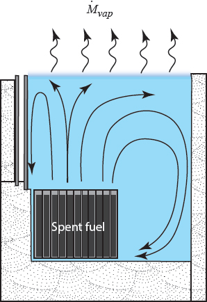
Following the loss of active cooling in a pool, the thermal power (decay heat) ![]() sf from the stored spent fuel heats the water and changes its buoyancy, which creates circulation within the pool. Water rises through the assemblies to the surface of the pool where some of it evaporates, cooling the water at the surface. This cooler water sinks into the pool. Some of it mixes with the rising warmer water in the central portion of the pool, and some of it sinks to the bottom along the sides and unracked parts of the pool, travels under the racks, and is entrained into the flow produced by the rising hot fluid inside the fuel assemblies (Figure 2B.1).
sf from the stored spent fuel heats the water and changes its buoyancy, which creates circulation within the pool. Water rises through the assemblies to the surface of the pool where some of it evaporates, cooling the water at the surface. This cooler water sinks into the pool. Some of it mixes with the rising warmer water in the central portion of the pool, and some of it sinks to the bottom along the sides and unracked parts of the pool, travels under the racks, and is entrained into the flow produced by the rising hot fluid inside the fuel assemblies (Figure 2B.1).
Assuming that the mass M of water within the pool is well mixed and at common temperature T, the conservation of energy in the pool can approximately modeled as
![]()
where Cp is the water specific heat capacity, ΔHfg is the heat of vaporization, Ṁvap is the rate of vaporization from the pool, ΔT is the difference between the pool and added water temperature, and Ṁadd is the rate at which water is being added to the pool. The thermal power (decay heat) ![]() sf of the spent fuel is balanced primarily by the energy loss due to vaporization as represented by the term ΔHfgṀvap. There is a much smaller (about 10 percent of decay heat in Unit 4) loss of energy,
sf of the spent fuel is balanced primarily by the energy loss due to vaporization as represented by the term ΔHfgṀvap. There is a much smaller (about 10 percent of decay heat in Unit 4) loss of energy, ![]() loss, through radiation and convection from the pool upper surface and conduction to the pool liner and concrete; these losses were estimated by EPRI (2012a) and TEPCO (2012a, Attachment 9-1) and are modest but not negligible. The committee has used the values1 proposed by TEPCO for the purposes of estimating approximate times for heat-up and evaporation of spent fuel pools.
loss, through radiation and convection from the pool upper surface and conduction to the pool liner and concrete; these losses were estimated by EPRI (2012a) and TEPCO (2012a, Attachment 9-1) and are modest but not negligible. The committee has used the values1 proposed by TEPCO for the purposes of estimating approximate times for heat-up and evaporation of spent fuel pools.
The conservation of mass can be modeled as
![]()
___________________
1 Unit 1, 0.08 MW; Unit 2, 0.11 MW; Unit 3, 0.11 MW; Unit 4, 0.16 MW. The heat loss rates for Unit 5, Unit 6, and the common pools were not given by TEPCO; the committee estimated a value of 0.11 MW for Units 5 and 6, and 0.33 MW for the common pool.
The rate of vaporization, Ṁvap, depends on the mass transfer rate across the layer of water vapor (steam) in the air above the surface of the pool (Figure 2B.2). The vaporization creates a humid atmosphere above the pool if the reactor building is intact. This will reduce the vaporization rate for a given pool temperature, and, if the vaporization rate is fixed, this will increase the pool temperature. Additionally, the evaporated water will condense on the interior of the cold reactor building with some fraction returning to the pool. In certain MELCOR simulations, the net effect is to decrease the rate at which the pool water level decreases by up to a factor of 2 over the situation in Unit 4 where the building structure was demolished (Gauntt et al., 2012, p. 192).
The rate of water addition to the pool, Ṁadd, is determined by the effectiveness of mitigation measures and possible infiltration from the reactor well through the gates (see Appendix 2C), offset by the rate of water
leakage, Ṁleak, from the pool, which depends on the size and location of the leak. Added water will typically be cooler than that in the pool, so some of the decay heat is used to raise the temperature of the water by ΔT = T – Tadd. In the simplest implementation of the pool energy-balance model, the water specific heat capacity (Cp) is assumed to be constant at 4.184 kJ/kg K and the heat of vaporization is also assumed to be constant, ΔHfg = 2.3 MJ/kg. At Fukushima, the added water temperature was about 10°C, and the initial pool temperatures were about 30°C before the loss of pool cooling.
The effect of a humid atmosphere on water evaporation from the pool can be predicted by a simple engineering model for the mass transfer based on a correlation for the mass transfer coefficient hm to find the evaporation rate through the water-air surface area A:
![]()
where ρsat(T) is the mass density of the saturated water vapor at temperature T.
The mass transfer coefficient can be estimated as
![]()
where Sh is the Sherwood number, D is the mass diffusivity of water vapor in air, and W is the characteristic dimension of the pool surface, in this case the width. The Sherwood number depends on the conditions in the mixed water vapor–air layer above the pool, particularly the air temperature, relative humidity, and air circulation rates within the building or wind conditions for an exposed pool; see the discussion by Wang et al. (2012) and Hugo and Omberg (2015).
The flow within the water vapor–air layer about the pool is turbulent; it is difficult to accurately predict the vaporization rates with certainty even if the conditions above the pool are known or can be reliably estimated. As a consequence, vaporization rates estimated by mass transfer correlations are highly uncertain (Hugo and Omberg, 2015). Fortunately, the quasi-steady-state energy-balance method does not rely on the mass transfer computation, and reliable predictions of vaporization rates can be made as long as the pool temperature and thermal radiation losses can be estimated or are known from measurements.
Without mitigation, the pool will heat up until a quasi-steady-state equilibrium condition is reached in which the rate of energy loss due to vaporization balances the thermal power input from the spent fuel, ![]() sf, correcting for the heat lost by radiation, conduction, and convection with the term
sf, correcting for the heat lost by radiation, conduction, and convection with the term ![]() loss, which is estimated using engineering correlations2 for heat transfer:
loss, which is estimated using engineering correlations2 for heat transfer:
![]()
Values of the effective thermal energy input rate ![]() ′ are given in column 3 of Table 2B.1. In the range from 30°C to 90°C, the heat of vaporization, ΔHfg, varies only slightly3 with temperature so that an estimate of the vaporization rate can be obtained using the nominal value of 2.3 MJ/kg. At the steady-state condition, termed thermal equilibrium, the temperature of
′ are given in column 3 of Table 2B.1. In the range from 30°C to 90°C, the heat of vaporization, ΔHfg, varies only slightly3 with temperature so that an estimate of the vaporization rate can be obtained using the nominal value of 2.3 MJ/kg. At the steady-state condition, termed thermal equilibrium, the temperature of
___________________
2 The value of the effective heat transfer coefficient from the surface will vary with pool temperature but the variation is modest, ranging from 10.4 W/m2 K for the Unit 1 pool up to 12.4 W/m2 K for the Unit 4 pool. TEPCO used a value of 11.6 W/m2 K in its estimates. Conduction heat transfer is transient and the rate of energy loss will decrease with increasing time.
3 The enthalpy of vaporization varies from 2,430 to 2,282 kJ/kg K, a variation of about 6 percent over this range.
TABLE 2B.1 Model Estimates for the Spent Fuel Pools at the Fukushima Daiichi Plant
| Unit | Mo (tonne) |
(MW) |
Teqb (oC) |
theat (day) |
Ṁevap (tonne/day) |
tmid (day) |
|---|---|---|---|---|---|---|
| 1 | 990 | 0.10 | 55 | 12 | 4.0 | 229 |
| 2 | 1383 | 0.51 | 70 | 5.3 | 19 | 63 |
| 3 | 1383 | 0.43 | 68 | 5.9 | 16 | 74 |
| 4 | 1383 | 2.10 | 88 | 1.9 | 79 | 16 |
| 5 | 1383 | 0.90 | 69 | 2.9 | 34 | 35 |
| 6 | 1453 | 0.76 | 68 | 3.5 | 29 | 44 |
| Common | 3716 | 0.77 | 73 | 10 | 29 | 110 |
a The values shown are the effective thermal energy input rate (decay heat minus thermal energy losses due to heat transfer) and are lower than the decay heat values given in Table 2.1.
b Values for Units 1-4 based on estimates from Wang et al. (2012). Other values based on maximum measured temperatures.
the pool attains a maximum value consistent with a vaporization rate that results in removing energy at a rate that exactly balances the decay heat generated by the spent fuel minus the heat transfer losses.
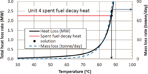
The result of the committee’s energy balance and vaporization rate computation4 for the Unit 4 pool is shown in Figure 2B.3. Equilibrium temperatures for the Fukushima Daiichi pools are predicted to be between 55°C and 88°C depending on the particular pool; this range is comparable to the actual measured values. The equilibrium temperature for the Unit 4 pool is predicted by the committee’s model to be 87°C, and the vaporization rate is about 0.9 kg/s (78 tonne/day). The measured pool temperature was about 84°C on March 14, 2011, and about 90°C on April 12, 2011.
2B.1 MODEL RESULTS FOR FUKUSHIMA POOLS
The committee applied a simplified version of this model to the initial stage of a Fukushima-like scenario of loss of pool cooling without mitigation or leakage. The energy addition to pool water is divided into two
___________________
4 The committee’s computation used the “stagnation film boundary layer” mass transfer analysis accounting for induced convection and the significant mass fraction of water in the region above the pool surface; see the discussion by Lienhard and Lienhard (2015, Section 11.8). The computational result shown in Figure 2B.3 accounted for the temperature dependence of all thermophysical properties and is similar in concept to that used by Wang et al. (2012) but included conventional engineering models of the convective, radiative, and conduction energy losses as well as evaporative losses.
steps. First, pool water heats up until the surface reaches the equilibrium temperature with negligible loss of mass:
![]()
Second, the water in the pool remains at constant temperature and evaporates:
![]()
Based on these simplifications, the time to heat a pool of mass Mo to the equilibrium temperature Teq from the initial temperature T0 is given by
![]()
The mass of the pool at a time t relative to the end of the heating period will be
![]()
This estimate is reasonable until the water level approaches the top of active fuel and a two-phase (water vapor and liquid) mixture is created due to boiling in water surrounding the spent fuel. Evaporative cooling will become progressively less effective as water continues to be vaporized and the channels of the fuel assemblies are filled with steam or a two-phase mixture rather than liquid water. Simulations by Sandia using MELCOR (Gauntt et al., 2012, p. 192) indicate that, for the conditions of the Unit 4 pool, the assumption of a constant vaporization rate appears to be approximately valid up until the collapsed water level reaches the midplane (2.2 m above the pool floor) of the active portion of the fuel assembly. A comparison between the committee model and the MELCOR results for the case of a full pool with no building (Gauntt et al., 2012, Figure 118) is shown in Figure 2B.4.
The comparison in Figure 2B.4 demonstrates that the simplified model of the committee is in reasonable agreement with the MELCOR model and overpredicts the time to reach the fuel midplane by 6 to 13 percent (1 to 2 days) depending on the assumptions about energy loss. This over-prediction is reasonable given that the committee’s model does not account for the reduction in water cross-sectional area within the racks and other phenomena such as fuel temperature increase and heat transfer into the racks. With this validation of the modeling approach, the time tmid required for the collapsed water level to reach the critical height corresponding to the midplane of the fuel for all pools can be estimated by computing the time needed to evaporate the water ΔMmid above this elevation:
![]()
The results are given in the last column of Table 2B.1. The amount of water loss, ΔMmid, corresponding to a reduction in pool collapsed water level to the midplane of the fuel will depend on the occupancy of each pool. Accounting for the reduction in pool volume within the rack area, we estimate values of about 700 tonnes for Unit 1, 950 tonnes for Units 2-6, and 2,400 tonnes for the common pool.
The results clearly indicate that the Unit 4 pool was of greatest concern and that, unless there was a leak or other substantial loss of water due to the earthquake-induced sloshing, there was no immediate need to deal with
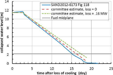
the other pools for the first month after March 11, 2011. Unfortunately, the status of the pools was initially unknown so that, while these estimates are straightforward, it was difficult for the Fukushima Daiichi plant operators and TEPCO to have confidence in these results in the absence of any measurements of pool level and temperature.
To evaluate alternate outcomes of the Fukushima accident for Unit 4, one must evaluate the thermal power in the pool for times earlier than March 11. This was done using the Wigner-Way model of decay heat (Lewis, 2008, Equation 1.27)
![]()
and adjusting the parameters ![]() th = 2,390 MW and tic = 1,000 days5 by fitting the decay heat to the TEPCO estimates (TEPCO, 2012a), which are
th = 2,390 MW and tic = 1,000 days5 by fitting the decay heat to the TEPCO estimates (TEPCO, 2012a), which are
___________________
5 The parameters in the equation are ![]() th, the reactor thermal power, and tic, the time the spent fuel has been at power in the core. Because there was a mix of different age fuel in the pool, the values obtained from the fitting process cannot be interpreted literally.
th, the reactor thermal power, and tic, the time the spent fuel has been at power in the core. Because there was a mix of different age fuel in the pool, the values obtained from the fitting process cannot be interpreted literally.
based on a realistic representation of reactor core neutron distribution and a detailed model of radionuclide generation and decay. The results of the fit are shown in Figure 2B.5.
Another application of this model is to determine the addition rate of water required to maintain steady-state conditions within the pool, i.e., constant temperature and mass. Applying these conditions to the mass and energy balance we obtain the required mass addition rate to maintain pool cooling:
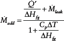
As expected, the mass added must be sufficient to compensate for both the leak as well as the evaporation. The term in the denominator accounts for the thermal power used to heat the cooler added water to the pool temperature; evaluating this for a pool temperature of 90oC, we find that the
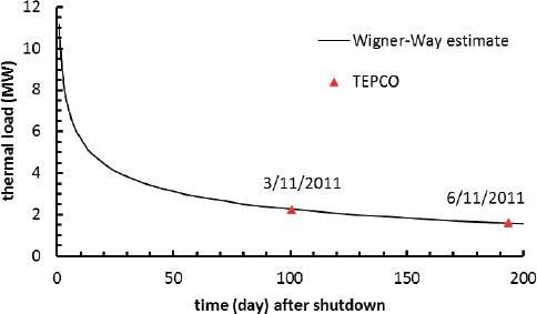
denominator is less than or equal to 1.1 and makes a negligible correction to the intuitive result,
![]()
The first term on the right-hand side is just the rate of evaporation needed to keep the pool at constant temperature. For all but the smallest of leaks, the mass addition rate required to maintain the pool level constant will be determined by the size of the leak rather than by the evaporation rate needed for thermal equilibrium. This is because the rate of evaporation needed even for 10-day-old fuel is only 40 gpm (220 tonne/day).
APPENDIX 2C
Orifice Flow-Rate Correlation
The committee estimated leakage rates around the gate seals in the Unit 4 spent fuel pool using the conventional orifice flow rate correlation:
![]()
where ![]() is the volumetric flow rate, Cf is the pressure drop coefficient (an empirical value, taken to be 0.6 for the purposes of this estimate), A0 is the flow-passage area, ΔP is the pressure drop across the gates,1 and ρ is the fluid density (in this case, the density of water in the pool).
is the volumetric flow rate, Cf is the pressure drop coefficient (an empirical value, taken to be 0.6 for the purposes of this estimate), A0 is the flow-passage area, ΔP is the pressure drop across the gates,1 and ρ is the fluid density (in this case, the density of water in the pool).
The value for ΔP was estimated using the average of the hydrostatic pressure due to the water-level difference between the reactor well (h1) and spent fuel pool (h2) measured from the bottom of the spent fuel pool:
![]()
where g is the acceleration due to gravity. Because of the gate design (see Figure 2C.1), leakage can occur when the water level in the reactor well is higher than in the spent fuel pool, that is, when ΔP is positive. The force of water created by a sufficiently higher level on the pool side than the well side pushes the gate toward the well side and squeezes an elastomer seal to stop the flow of water out of the pool.2 When the water level on the well side is higher than in the pool, the gate is mounted such that the force due to the difference in water level can displace the gate sufficiently that the seal is not effective and water will flow from the well into the pool; see the discussion in TEPCO (2012a, Attachment 9-1, p. 3/9).
Computations were carried out with various dimensions for flow-passage area (A0); the results for pool level history are insensitive to its exact value, resulting in variations in level within a band of ±0.5 m for effective seal openings between 0.1 and 5 mm (see Figure 2C.2). For this
___________________
1 In applying the formula to cases where the flow is bidirectional, the absolute value of the pressure difference is used and the sign of the volume flow rate is taken to be the same as the sign of the pressure difference.
2 When the level in the reactor well is slightly lower than that of the pool, TEPCO has proposed that sufficiently strong motion could dislodge the gate and allow water to flow from the pool to the well side; see the discussion of the effect of the January 1, 2012, earthquake in http://www.tepco.co.jp/en/nu/fukushima-np/roadmap/images/m120123_02-e.pdf.
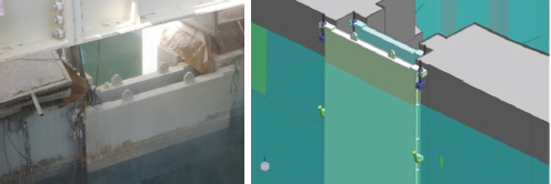
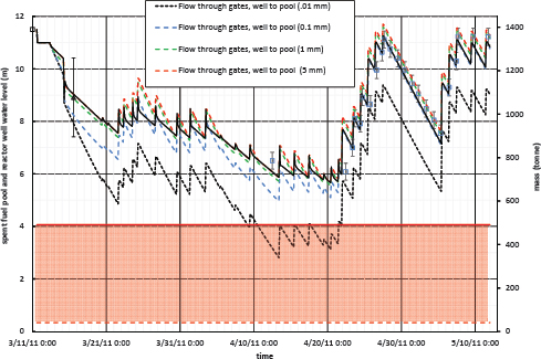
range in seal openings, the total amount of water transferred between the reactor well and pool varied from about 650 to 710 tonnes, consistent with the measured reactor well water level on April 27, 2011. The water-level history before April 22 (when the gate seals appeared to become effective again3) was also insensitive to the assumptions about the directionality of water flow. Assuming that water could flow in both directions resulted in only a 0.5-m difference in pool level on April 22, 2011. In Figures 2.15 and 2.16, a value of 1.0 mm for the effective width of the flow-passage area was used and the height of the flow passage was taken to be equal to the difference in levels between the reactor well and spent fuel pool.
Once the leakage rate is computed, water levels in the reactor well and dryer-separator pit can be estimated using the mass balance as discussed in Appendix 2B. The reactor well and dryer-separator pit are estimated to have a combined volume of 1,400 m3 and surface area of 172 m2; these values are given by TEPCO (2012a, Attachment 9-1, Table 3; 2012b) and are consistent with other published data.4 The committee-estimated water levels in the reactor well and dryer-separator pit are shown by the orange curve in Figure 2.15.5
___________________
3 It is unclear why the gate seals regained effectiveness after April 22. The gates are just hung in place; their sealing depends on the force created by differential water levels between the pool and reactor well. This force increased substantially with the water addition to the pool on April 22.
4 The values we have used are different than those given by other investigators such as EPRI (2012a), which reflects the difficulty of obtaining reliable data for complex geometries in the outage condition as well as uncertainty about the precise dimensions of the reactor buildings.
5 The committee-computed water levels in the reactor well and dryer-separator pit are in good agreement with the TEPCO water-level measurement on April 27, 2011 (black square in Figure 2.15).


