


Below is the uncorrected machine-read text of this chapter, intended to provide our own search engines and external engines with highly rich, chapter-representative searchable text of each book. Because it is UNCORRECTED material, please consider the following text as a useful but insufficient proxy for the authoritative book pages.
19 CHAPTER FOUR PIPE MATERIALS Definition of Useful Service Life Durability requirements vary considerably between agen- cies owing to the very wide range of environments encoun- tered and the agenciesâ different durability requirements. In practice, the expected service life of concrete pipe is gener- ally 75 to 100 years. Service life of concrete pipe depends greatly on the class of pipe and the environment in which it is installed. Assum- ing a single value for the service life of concrete pipe does not reflect the variation in the environments in which the pipes are installed. A number of prediction methods have been devel- oped by various agencies and researchers to determine the expected service life of concrete pipe. Also, agencies have no standard definition of what constitutes a critical failure condi- tion for concrete pipe as a result of corrosion or other deteriora- tion mechanisms. Examples of agenciesâ estimated expected service lives for concrete pipe use include the following: ⢠Utah DOT tests soil and water for resistivity, pH, sol- uble salts, and sulfate content, then uses charts to esti- mate the expected service life for various types of pipe. The expected service life of Portland cement concrete can be up to approximately 120 years (Molinas and Mommandi 2009). ⢠Arizona DOT assigns concrete pipe a service life of 100 years for installations where the pH is 5 or greater (Molinas and Mommandi 2009). ⢠The U.S. Forest Service has defined acceptable condi- tions for concrete pipe to resist corrosion (Molinas and Mommandi 2009). If the pH of the water or soil surround- ing the pipe is between 4.5 and 10 and the resistivity of the soil is greater than 1,500 ohm-cm, then the expected cor- rosion service life of concrete pipe is 75 years or greater. ⢠A literature review by the National Research Council of Canada (Zhao 1998) stated, based on various studies in the United States, that the predicted service life of concrete pipe varies from 50 to more than 100 years, depending on the environmental conditions to which the pipe is subjected. ⢠A survey by the New York State Department of Transportation (Molinas and Mommandi 2009) found the useful life of concrete pipe varied from 20 to 75 years with an average of 56.3 years. This chapter summarizes the key issues, definitions, and design methods used to evaluate the service life of culvert materials. Each major pipe material type is discussed in a separate section. CONCRETE PIPE Material Properties and Specifications In general, material properties for concrete pipes are defined by ASTM and AASHTO standards as listed in the AASHTO LRFD Bridge Manual (AASHTO 2013), which states in Sec- tion 12.4.2 that: ⢠Concrete shall conform to Article 5.4 of the LRFD Bridge Manual. ⢠Precast concrete pipe shall comply with the require- ments of AASHTO M 170 (ASTM C76) and M 242M/M 242 (ASTM C655M and C655). Design-wall thickness, other than the standard wall dimensions, may be used, provided that the design complies with all applicable requirements of Section 12.4.2. ⢠Precast concrete arch, elliptical, and box structures shall comply with the requirements of AASHTO M 206M/M 206 (ASTM C506M and C506), M 207M/M 207 (ASTM C507M and C507), M 259 (ASTM C789), and M 273 (ASTM C850). ⢠Steel reinforcement shall comply with the require- ments of Article 5.4.3, and shall conform to one of the following: â AASHTO M 31M/M 31 (ASTM A615M/A615), â AASHTO M 32M/M 32 (ASTM A82M/A82), â AASHTO M 55M/M 55 (ASTM A185M/A185), â AASHTO M 221M/M 221 (ASTM A497), or â AASHTO M 225M/M 225 (ASTM A496M/A496). AASHTO (2007) Chapter 14 provides the following rec- ommendations for concrete pipe: ⢠Sulfate concentration must be less than 1,000 ppm. ⢠Extra concrete cover over steel reinforcement is rec- ommended when abrasion is severe. ⢠Extra steel cover or coated steel is also recommended when the pH is less than 5.5.
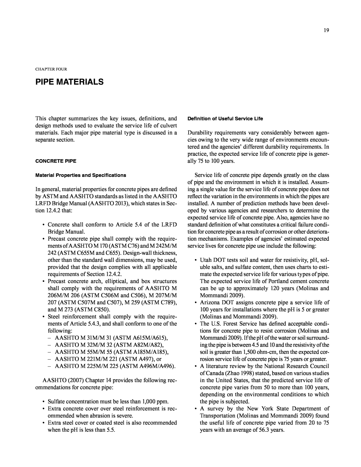
20 ⢠A study commissioned by Ohio DOT (Mitchell et al. 2005) found from a survey of 40 DOTs that service life of concrete culverts appeared to be limited to 70 to 80 years. The most frequently encountered conditions were deteriorated headwalls, deterioration of concrete in the crown region or top slab and inlet walls, and transverse shear cracks on abutment walls. Factors Affecting Service Life Pipe Construction and Concrete Properties Pipe material properties are critical to resisting potential durability impacts. For reinforced concrete pipe, the pre- dominant pipe material properties impacting durability are (after ACPA 2008): ⢠Compressive strength ⢠Density ⢠Absorption ⢠Cement content and type ⢠Aggregate characteristics ⢠Water cement ratio ⢠Air entrainment ⢠Concrete cover of reinforcement ⢠Steel reinforcement characteristics and coatings. Corrosion Corrosion of the reinforcing steel is the primary concern when considering corrosion for concrete pipes. Corrosion of reinforcing steel can lead to spalling, cracking, and further susceptibility to corrosion. Corrosion of reinforcing steel in concrete pipe occurs when moisture, oxygen, and chlorides reach the steel. Rein- forced concrete corrosion is a result of the quality of the con- crete, its permeability, the thickness of the cover, and the presence of cracks in the concrete pipe. Its deterioration fol- lows the service life mechanisms detailed in Figure 20. FIGURE 20 Steel-reinforced concrete corrosion service life diagram (FDOT 2014b). Selecting the proper pipe class and inspecting the pipe before installation can minimize the risk of damage to pipes being installed. Chlorides, which accelerate corrosion, are most often associated with the use of road salt or exposure to seawater in coastal areas. Even in aggressive environments for corrosion, a service life of 100 years is achievable with the proper selection of concrete class and pipe design. Pipe Cracking and Steel Corrosion Cracks in reinforced concrete pipes can occur for a num- ber of reasons, including drying shrinkage or impact during shipping, handling, and installation. Concrete cracks are not always a durability risk on their own, but more critically they can allow for corrosion through chloride attack of the rein- forcing steel. Increased concrete cover and low-permeability concrete with an absence of voids and cracks will reduce or delay the severity of chloride attack. The LRFD Bridge Construction Specifications (AAS- HTO 2010) specifies a maximum in-place width of 0.100 in. for noncorrosive conditions and 0.010 in. for corrosive conditions. The general view was that in the case of very narrow cracks, the process of concrete leachate interacting with atmospheric or waterborne CO2 would cause calcite and other carbonate deposits that would seal such cracks. This process is referred to as autogenous healing. Larger in- place RCP cracks can degrade pipe performance by decreas- ing structural strength and dimensional stability, which permits leaks, and by allowing premature corrosion of steel reinforcement (Sagüés et al. 2001). Such corrosion, once ini- tiated, has the potential to lead to concrete spalls, causing increased pipe roughness and leading to reduced pipe-wall- bearing thickness and loss of serviceability. FDOT initiated a study at South Florida University (Busba et al. 2011) to investigate this phenomenon and develop guidelines for acceptable concrete pipe crack widths during construction. The research found that: ⢠Significant autogenous healing was not detected in cracks as narrow as 0.020 in. during their experiments; ⢠Corrosion tests showed that significant reinforcement corrosion took place in a short period of time with 0.100-in.-wide cracks, but that corrosion damage was much slower with cracks 0.020 in. wide; and ⢠Based on the corrosion testing and model projections, cracks of up to about 0.020 in. on the inner pipe face are acceptable up to moderately aggressive environ- ments. However, allowable crack width limits above 0.100 in. are not acceptable under any circumstances. Thus as crack widths increase above 0.020 in. and where exposure to environmental chlorides increase above about 500 ppm, significant reduction in predicted RCP service life should be anticipated with the likely deterioration mode
21 being concrete spalling caused by corrosion of reinforce- ment (Figure 21). Sulfate Damage High sulfates in soil, groundwater, and flow water can cause sulfate-related damage to concrete over time. Various thresh- old levels for sulfates are used by various agencies. Typi- cally, an upper level is defined for sulfates where no special precautions are needed. Above this threshold, concrete pipe can still be used; however, special mix designs are required. Special mixes typically require either sulfate-resistant cement, higher cement contents, or the use of supplementary cementitious materials such as fly ash, slag, silica fume, and so on, to provide some resistance to sulfate attack. The rela- tionship is the smaller the quantity of tricalcium aluminate (C3A) in the hydrated cement, the lower the vulnerability to sulfate attack. ASTM C 150 limits Type II cement, moder- ately sulfate resisting, to a maximum of 8% C3A; Type V cement, identified as sulfate resisting, is limited to 5% C3A. An upper threshold for sulfates can be defined to deter- mine where concrete pipe is not to be used. For example, in Utah (Molinas and Mommandi 2009), if the sulfate content of the surrounding soil is less than 0.5%, Type II cement can be used. If the sulfate content is greater than 0.5%, then Type V cement is used. Often the guidelines in Chapter 4 of ACI 318, Building Code Requirements for Structural Concrete, are used to specify the type of cement to be used, or blended cement is used to address concerns related to potential sulfate attack on concrete (ACI 318 2011). Acid Attack Acid will attack the exposed surface of portland cement concrete. Acids are naturally neutralized by the alkalinity of concrete, and so without acid replenishment the adverse impacts of acid are not of concern. According to the ACPA (2008), continuous replen- ishment of acid with a pH below 5 is an aggressive environment, and a pH below 4 is a highly aggressive environment. Three common types of acidic attack are (ACPA 2008): ⢠Biochemical, which occurs in a sanitary sewer. The acid involved is always sulfuric (H2SO4) and the attack is confined to the interior, unsubmerged perimeter part of the pipe. ⢠Effluents that are acidic in nature. Attack is confined to the wetted interior surface of the pipe. ⢠Exterior acid attack resulting from acidic groundwater, backfill, or natural soils. The most common areas prone to exterior acid attack are areas of acid mine drainage, sanitary, or industrial waste facilities. FIGURE 21 Progression of corrosion in RCP with a 0.100-in. crack exposed to chloride solution after (a) 6 days, (b) 20 days, (c) 34 days, and (d) 52 days (Busba et al. 2011).
22 If either interior or exterior acidic conditions are esti- mated or encountered, and cannot be alleviated by other countermeasures, the following special acid protection pro- visions are recommended by the ACPA (2008): ⢠Increased total concrete alkalinity ⢠Increased/sacrificial concrete cover ⢠Use of protective coatings ⢠Use of low permeability and/or alkaline (e.g., lime- stone) backfill. Abrasion Abrasion is not a problem typically associated with concrete pipe. Most high-abrasion conditions are short-term events (e.g., spring runoff from storms). Abrasion is usually only considered relevant for the design of concrete pipe in severe abrasive conditions. The following list includes the general ways agencies pro- vide abrasion resistance for concrete pipes, though some of these methods conflict with FHWA aquatic organism pas- sage guidance: ⢠Use a paved invert. ⢠Provide an upstream catchment device to restrict bed- load from passing through the culvert. ⢠Limit the use of concrete pipe to slopes flatter than a certain value (thereby limiting flow velocity). ⢠Require a mechanical barrier (epoxy liner). ⢠Select a higher class of pipe (higher concrete strength) or modify the mix design. ⢠Specify thicker walls (for protection of steel reinforcing). One parameter that influences the abrasion of concrete pipe is the hardness of the aggregate used in the concrete. Aggregates that are harder than the bedload will provide a greater level of resistance to abrasion than softer aggregates. Based on the literature search, the authors did not find any states that explicitly considered aggregate hardnessâs effect on abrasion resistance. Other Factors Joint performanceârelated issues frequently cause many types of culvert and storm sewer pipe failures. The relatively short length of concrete pipe sections (generally 8-ft-long sections are manufactured) requires a larger number of joints than flexible types of pipe. If the pipe joint separates or fails, material can enter the pipe from the surrounding back- fill, leading to loss of ground and, on some occasions, to the formation of sinkholes in the roadway above. Joints, if not appropriate for the application or if not properly installed, can become the weak link in a buried pipe system and can become the controlling factor in causing the end of useful service life. The AASHTO Subcommittee on Materials PP 6309, âStandard Practice for Pipe Joint Selection for High- way Culverts and Storm Drainsâ (AASHTO 2009), is the most comprehensive guide on the selection of pipe joints. It provides definitions of soil-tight, silt-tight, leak-resistant, and special joints, depending on project or site requirements. A recent study for Minnesota DOT (Taylor and Marr 2012) indicates that joint separation is the most common fail- ure mode of concrete pipe in Minnesota DOT experience. This report recommends the longer joint and more favorable joint geometrics provided by gasketed joints to reduce the incidence of failure resulting from joint separation. Concrete pipes can also undergo damage from progres- sive deterioration of the concrete. This deterioration can result from the use of poor quality concrete mixes or non- durable aggregates, or from poor-quality construction. This type of damage manifests as efflorescence, honeycombing, and popouts. Methods to Estimate Concrete Pipe Material Service Life The most commonly accepted methods for estimating the service life of concrete pipes are listed in Table 6. They are: TABLE 6 METHODS FOR DETERMINING ESTIMATED MATERIAL SERVICE LIFE FOR REINFORCED CONCRETE PIPE Durability Method Reference Notes Ohio DOT Model Potter (1988) Based on large data set over a wide range of pH and size values. Includes an abrasive component. Note that this method is not cur- rently used by Ohio DOT, which has generated recommendations based on the Hurd model. Hurd Model Potter (1988) Method developed for large- diameter pipes in acidic environments. Hadipriono Model Potter (1988) Method includes a wide pH range. Florida DOT Model Drainage Manual- Optional Pipe Handbook (FDOT, 2012) Considers corrosion and sul- phate attack but not abrasion. ⢠Hurd model (Hurd 1985) ⢠Hadipriono model (Hadipriono 1986) ⢠Florida model (FDOT 2014a) ⢠Ohio DOT model (Meacham et al. 1982). The Hurd and Hadipriono models are both based on the same data set from Ohio DOT, but they use different regres- sion models and exclude various subsets of the overall data set. Factors considered in these models include pH, slope, sediment depth, and diameter. The Florida model assumes that corrosion is the critical degradation mechanism and
23 includes such factors as depth of steel cover, chloride and sulfate concentrations, and concrete mix in its equation, which the other models do not explicitly incorporate. Potter (1988) and Gabriel and Moran (1998) provide more detailed discussions and descriptions of these methods. In addition to the previous quantitative methods, review and comparison to the achieved service life of nearby instal- lations is often used to provide both qualitative and quantita- tive (through back-calculation of environmental parameters) material service life estimates. The formulas representing each of these four service life prediction models are provided in detail in Appendix B âAluminized Steel (Type 2) Pipe) along with supporting charts and tables for the FDOT model. METAL PIPE Material Properties and Specifications Material properties for metal pipes are generally defined by ASTM and AASHTO standards as listed in the AAS- HTO LRFD Bridge Manual (2013), which states in Section 12.4.2 that: ⢠Aluminum for corrugated metal pipe and pipe-arches shall comply with the requirements of AASHTO M 196 (ASTM B745). Aluminum for structural plate pipe, pipe-arch, arch, and box structures shall meet the requirements of AASHTO M 219 (ASTM B746). ⢠Steel for corrugated metal pipe and pipe-arches shall comply with the requirements of AASHTO M 36 (ASTM A760). Steel for structural plate pipe, pipe-arch, arch, and box structures shall meet the requirements of AASHTO M 167M/M 167 (ASTM A761M/A761). ⢠Steel for deep-corrugated structural plate shall comply with the requirements of AASHTO M 167. Deep-corrugated structural plate may be reinforced (Figure 22). The current state of practice is summarized in Table 7 in the form of a list of findings from relevant studies grouped by topic. Definition of Useful Service Life The most common definitions of useful service life of metal culverts relate to the loss of wall section. Typical service life criteria relate to section loss as a result of the subsequent reduction in structural capacity and the poten- tial for soil erosion through the pipe wall, which can lead to significant softening of the backfill, ground loss, and the potential for significant sudden and dangerous impacts to the overlying roadway. FIGURE 22 Older invert paved corrugated steel culvert in excellent condition (NYSDOT 2011). Halem et al. (2008) provides a clear and concise summary of the most common serviceability criteria used for steel culverts. The California method (Caltrans 2001) defines service life as the time to first perforation, while the American Iron and Steel Institute (AISI) method indicates that first perforation typically occurs when there is an average metal loss of 13% in the invert of a pipe (Figure 23). However, AISI defines the end of the use- ful service life of the pipe as the time when an average metal loss of 25% occurs in the invert. Therefore, AISI predicts the service life to be approximately twice as long as that of the Cali- fornia method. The National Corrugated Steel Pipe Association (NCSPA) has also published a corrugated steel pipe durability guide that uses the AISI chart to predict the service life of cor- rugated steel pipe and provides a table with additional service life durations for different coatings (NCSPA 2000). FIGURE 23 Perforated invert of metal culvert (Caltrans 2013). The state of the practice across transportation agencies appears to vary widely based on the responses to survey questions 3B to 3F related to the definition of end of service life for metal culverts as presented in full in Appendix A. Factors Affecting Service Life The extensive research work that agencies have undertaken on the subject of factors affecting the service life of metal
24 cal processes. The majority of failures in metal pipes are attributed to corrosion, which can degrade both the inside (flow side) and outside (soil side) of a culvert. Soil-side corrosion is most significant in arid or semi-arid regions where the soils are generally alkaline (high pH) and rain- fall is minimal. pH generally controls the potential for cor- rosion to occur, with resistivity generally controlling the rate at which it occurs. culverts indicates its importance in managing drainage net- work maintenance and replacement costs. Table 7 provides a summary of this research and relevant findings. Corrosion As defined earlier, corrosion is the loss of section or coat- ing of a buried structure by chemical or electrochemi- TABLE 7 METAL PIPE DURABILITY AND SERVICE LIFE Factor Standards of Practice Reference General Most states have found that pH and resistivity of the contacting soil and water bodies correlate well to culvert durabil- ity. Based on combination of pH and resistivity, Montana DOT selects either plain steel, type 2 aluminized steel, alumi- num, or concrete. Wyant (2002) Utah DOT has a guideline to select the material for both metal culverts and concrete culverts based on pH, resistivity, and percent-soluble salt. Wyant (2002) Studies from the New York and North Carolina DOTs concluded that no correlation exists between pipe service life and pH, resistivity, or chemical content of the soil. These studies stand in contrast to other studies that indicate that pH and resistivity are important and correlative factors affecting durability. New York DOT developed a method to use galvanized steel pipe (with or without invert paving) based on the culvert location. Gabriel and Moran (1998) Corrosion It is common to specify both upper and lower bounds for pH. Typical ranges for plain galvanized steel: Alabama: 6.5 < pH < 8.5 Montana: 6.0 < pH < 8.5 Washington: 5.0 < pH < 8.5 Idaho: 6 < pH < 9 AASHTO (2007): 5.5 < pH < 8.5 Typical ranges for aluminized steel: Idaho: 5 < pH < 9 Gabriel and Moran (1998) Because of problems with rapid corrosion damage, general use of plain steel culverts (excepting steel casing pipe) is prohibited in Colorado, Louisiana, and Ohio. Gabriel and Moran (1998) Resistivity for both the contacting soil and water should be determined; e.g., California Test 643. The minimum resis- tivity is then used to estimate the culvert service life. Caltrans (1999) Soil resistivity has more of an effect on corrosion than the water resistivity based on data from Alberta, Canada. Gabriel and Moran (1998) Soil-side and water- side corrosion Depending on the environmental conditions, loss of metal due to corrosion can occur on either the water side or the soil side of the culvert. Soil-side corrosion controls the pipe service life when site pH is greater than 7.3. NCSPA (2008) A study from Ohio concluded that water-side corrosion was the main factor leading to metal loss in deteriorated metal culverts in Ohio. Gabriel and Moran (1998) Abrasion Many states have found that abrasion from material being carried in the water flow has a significant effect on the dura- bility of metal culverts. Ohio DOT conducted a field study that involved 1,616 pipes and found that low water pH and abrasive bedloads were the two main factors affecting pipe service life. Its study concluded that resistivity did not have a significant impact on the pipe life. Meacham et al. (1982) A field abrasion study conducted in California between 2001 and 2006 concluded that only the polyethylene coating for steel culverts was suitable for abrasive environments with flow velocity > 12 ft/s, but was not suitable for velocities > 14 ft/s. Decou and Davies (2007) Abrasion, Corrosion, and Protection A combination of corrosion and abrasion accelerates wear in metal culverts and reduces culvert service life. Corrosion products act as a protective layer for bare steel; however, abrasion flow removes the corrosion layer and exposes the bare steel to further corrosion. A study from British Columbiaâs Ministry of Transportation evaluated 21 structural plate and galvanized drainage structures that were more than 20 years old in 1993. Based on corrosion alone, the service life was expected to exceed 100 years; however, two of the structures had significant loss of metal due to abrasion. CSPI (2007) Additional coatings prolong metal culvert service life by providing protection against corrosion and providing abrasion resistance. For example, bituminous coated steel culverts add an additional 10 years to water-side and 25 years to soil- side service life. If invert paving is added, the entire culvert life can be extended by an additional 25 years. Gabriel and Moran (1998) Conventional plain galvanized coating has very little resistance to abrasion. It can still be used in abrasive conditions if it is protected. A typical option is to install 3 to 6 in. of concrete over the lower one-third of the pipe. AASHTO (2007) The Ohio DOT study concluded that bituminous coated steel culverts without invert paving add little value in terms of service life because the average life (years to poor condition) of the bituminous coating was 3.16 years with 50% and 20% chance of coating lasting over 1.5 years and 5 years or more, respectively. Thus, the coating should be used in conjunction with invert paving where the average service life addition was 18.71 years. Meacham et al. (1982)
25 The expected material service life (EMSL) of polymer- coated steel pipes is generally calculated by adding on a number of years to the service life obtained from estimates for plain galvanized steel pipe. The protective performance of a coating will vary depending on the composition of the coating, quality of bonding, thickness of the coating, and expected abrasion conditions. Specific assumptions and methodologies used in the research and development of the add-on year values also vary. Various sources provide add- on values for polymer and other coatings: ⢠National Corrugated Steel Pipe Association â Pipe Selection Guide (NCSPA 2010) provides a table of service life add-ons for supplemental pav- ings and coatings. â Service life add-ons are dependent on the abrasion level (using FHWA scale from 1 to 4). â Service life add-on values range from 10 years to greater than 80 years. â Field inspection data on polymer-coated steel pipe installations from across a large range of states over several decades is provided in the NCSPAâs 2012 report, âLong-Term Field Investigation of Polymer Coated Corrugated Steel Pipeâ (NCSPA 2012). ⢠Highway Design Manual (Section 855) (Caltrans 2011b) â Service life add-ons are dependent on flow velocity, channel materials, and type of coating or paving. â Service life add-on values range from 0 to 70 years. The choice of additional service life owing to coatings is generally based on a qualitative assessment of the abra- sive conditions. Various definitions of these abrasive levels are available. The most widely adopted definition is that proposed by the Federal Highway Administration (FHWA 2011). Caltrans has also defined levels of abrasion based on a study performed in an area known to have highly abrasive conditions (Decou and Davies 2007). The NCSPA uses the FHWA definitions in providing guidance on the applicabil- ity of different coatings in different applications. Methods to Estimate Service Life Culvert service life will vary significantly depending on environmental conditions, but the typical expected service life of metal culverts can be 25 years, 50 years, or longer, depending on wall thickness and site environmental condi- tions. Table 8 summarizes the current approaches to estimat- ing metal pipe service life expectations. Galvanized Steel Pipe A number of methods are available for estimating the expected service life of galvanized pipe, as listed in Table 8. The most widely recognized methods are the Califor- Corrosion of steel is an electrochemical process in which the metallic iron is oxidized to form iron oxide or ferrous ions, depending on the environmentâs pH level. The presence of aggressive chemicals (such as chloride ions), inorganic acids, or low-pH environments can accelerate corrosion. It should be noted that while most studies have shown a defi- nite influence of pH and resistivity on corrosion of metal cul- verts, some studies do not show this trend. Generally, state agencies specify minimum and maximum pH and resistivity ranges for the installation of metal pipes. In an acidic environment (low pH), steel dissolution occurs, whereas in an alkali environment (high pH), steel forms an oxide film. Steel dissolution is thus more severe in an acidic environment because in an alkaline environment, the oxide film formed on the surface of the steel can stabilize it. This protective film can, however, be broken down in the presence of some ions (such as chloride ions) and when the pH is below approximately 8. A Caltrans study of metal pipe durability is the basis for most metal pipe service life prediction models (Caltrans 1999) and was based on life to first perforation in culverts that had not received any special maintenance treatment. The results included the combined effects of soil-side and interior corrosion, as well as the average effects of abrasion. For pipes where the pH was greater than 7.3, soil-side cor- rosion controlled and life could be predicted by resistivity. For pipes where the pH was less than 7.3, the interior invert corrosion generally controlled and both resistivity and pH were important. In the field inspection of 7,000 culverts in California for Caltrans, Richard Stratfull, lead project inves- tigator, states he âhas no memory of a corrosion perforation being initially found other than in the invertâ (NCSPA 2000). Because plain steel is vulnerable to corrosion, galvanized zinc coatings for steel pipe are standard practice. When zinc (or aluminized coatings) is applied to steel pipe, corrosion resistance increases. This coating provides a sacrificial metal- lic layer for acidic environments. Polymer laminates applied to steel pipes also provide a protective barrier against corrosion. Dissolved salts containing chloride ions can be present in the soil or water surrounding a culvert pipe. Chlorides primarily attack exposed metal and will also be of concern at coastal locations, near brackish water sources, and at loca- tions that use winter deicing salts. Abrasion Common practice in estimating the durability of metal cul- verts is to consider corrosion factors (pH and resistivity) assuming nonabrasive or low-abrasive conditions and then to separately consider abrasion as a supplemental evaluation of durability. With the development of new coatings, ongoing research is needed to update service life prediction models.
26 nia method and the AISI modified California method. The deterioration rates are based on the pH and resistivity of the flow and soil. The California method has been devel- oped based on surveying the condition of 7,000 corrugated metal culverts located in California (Beaton and Stratfull, 1962). The most recent version of the California method to estimate the service life of steel culverts is the Califor- nia Test 643 (Caltrans 2012). The methods differ, however, in the definition of the end of service life. The California method defines service life as the time to first perforation, whereas the modified California method permits a 25% loss of invert. Additional methods have been developed by Ohio and Utah DOTs. A recent study for Colorado DOT concluded that the California method works well with some adjustments to the metal thickness adjustment factors (Table 9). Montana DOT also recently performed a study and concluded that the method used to determine soil resistivity had a significant effect on the accuracy of the modified method. Neither of these two methods incorporates the effects of abrasion, or the differences between corrugated and structural plate pipe. In addition to the previous quantitative methods, review and comparison to the achieved service life of nearby instal- lations is often used to provide both qualitative and quantita- tive (through back-calculation of environmental parameters) material service life estimates. The NCSPA has also published a corrugated steel pipe durability guide that uses the AISI chart to predict service life of corrugated steel pipe and provides a table with additional service life durations for different coatings (NCSPA 2000). The Federal Lands Highway Division of FHWA uses a modified version of the California 643 method to estimate the service life of galvanized culverts for nonabrasive and low-abrasive conditions (FHWA 2011). The Federal Lands Highway guidance provides a detailed chart of estimated average service life values for a metallic-coated steel pipe with a thickness of 0.64 in. and assumes that the average service life for metal culverts should be taken as 25% longer than the time to first perforation. Missouri DOT defines the end of useful service life as the time to replacement of the pipe as a result of structural failure or erosion of the roadway bed above the pipe (Gabriel and Moran 1998). Both the California method and the AISI method use the thickness multiplier to estimate the service life of different gage thickness, and this multiplier was calculated based on the assumption of a linear relationship between corro- sion and thickness. However, Colorado DOT recommends a TABLE 8 CURRENT APPROACHES TO ESTIMATION OF THE SERVICE LIFE OF METAL CULVERTS Service Life Estimation Approach Reference Expected service life for metal culverts is reported as 50 years. Restrictions on allowable pH and resistivity lev- els for each type of metal culvert need to be applied to achieve this service life. Potter (1988) A study in Alberta evaluated the performance of 201 zinc-coated culverts in 1988 and showed that 83% of the installations achieved the minimum service life of 50 years and that the average expected service life was 83 years. CSPI (2007) A study conducted in Washington, D.C., evaluated the performance of 17 galvanized steel storm water deten- tion systems. Due to the absence of abrasion at invert, these steel culverts performed very well after 25 years of service. The study expected that these culverts would exceed 100 years of service life. NCSPA (2002d) Louisiana has developed a table to list design service life for each type of culvert and application. For metal culverts, the design service life ranges from 30 to 50 years. Wyant (2002) Caltrans has developed a chart to determine the wall thickness of various metal pipes needed to achieve 50 years of maintenance-free service life. It has also developed a guide to determine the minimum thickness of coating material at the invert to achieve a 50-year service under a range of abrasion levels. Caltrans (2011b) Chapter 14 of AASHTO (2007) defers to the Caltrans Test Method 643-C (California method) for estimating service life of galvanized corrugated steel pipe. AASHTO (2007) A study from Ontario in 1967 concluded that the predicted service life of culverts under local conditions agreed with the California method, based on pH and resistivity. CSPI (2007) A study in Alberta found a poor correlation between its results and the California method. The study also proposed that frost action slowed or stopped the metal corrosion process. Gabriel and Moran (1998) Colorado DOT has also developed a corrosion rating system modified from the Caltrans system. Wyant (2002) Florida, Louisiana, Idaho, Georgia, Nebraska, and Kansas have investigated the actual service life of culverts and compared them with the California method. They concluded that the California method was too conservative. Meegoda and Juliano (2009) A study commissioned by Ohio DOT found from a survey of 40 DOTs that with respect to metal culverts, no serious alignment problems were found at the sites. No stress cracks were detected at the bolt lines inside any of the metal culverts and the service life of a metal culvert appeared to be limited to 60 to 65 years. Mitchell et al. (2005) A study focusing on corrugated aluminized type 2 steel pipe found that in the absence of abrasion, aluminized type 2 pipe had a service life 3.5 times greater than the service life estimated for plain galvanized corrugated steel pipe via the California method, noting the reported accuracy of the California method as ±12 years. Ault and Ellor (2000)
27 power relationship between corrosion and thickness (Moli- nas and Mommandi 2009). The California Corrugated Steel Pipe Association found that the AISI method is appropriate for estimating the service life of the upper 270 degrees of the culvert circumference and recommended that the AISI method be used only when the invert is paved (Potter 1988). According to Ault and Ellor (2000), the California method has an accuracy of approximately 12 years. In 1982, Ohio DOT conducted a study to evaluate the field performance of 1,616 culverts in Ohio (Meacham et al. 1982). This study developed equations and a graph to calculate the expected years to poor condition of bituminous coated cul- verts and bituminous coatedâinvert paved culverts. This study also developed equations to predict the metal rating and metal loss based on age, water pH, wall thickness, and abrasion level for both corrugated metal pipe and structural plate pipe. The rating scale ranged from 1 (good) to 4 (criti- cal). Mitchell et al. (2005) indicates that the new Ohio DOT rating scale and proposed rating system ranges from 0 to 9 (9 indicates excellent condition, 1 indicates very poor condi- tion, and 0 indicates failure). The new rating scale (0 to 9) was converted from the old rating scale (1 to 4). New York DOT has developed a method to deploy gal- vanized culverts based on a âdurability index.â The index comprises four criteria: geographical area (rating of 1, 3, 5, 7, or 9), abrasion (rating of 1, 2, or 5), flow condition (rating of 1, 2, or 3), and service rating (1 or 2). If the index value is greater than 13, it is recommended that a paved (bituminous) invert be used. Otherwise, it recommends the use of plain galvanized culverts (Ault and Ellor 2000). A recent study from Colorado DOT (Molinas and Mom- mandi 2009) concluded that the California method worked well with some modifications to the metal thickness adjust- ment factors. Based on the flow velocity and the bedloads, the FHWA defines four levels of abrasion: nonabrasive, low abrasive, moderate abrasive, and severe abrasive (FHWA 2011). The Colorado DOT study recommended applying additional coating at the invert to adjust for the abrasion level. Montana DOT (Hepfner 2001) also performed a study and concluded that the method used to determine soil resis- tivity had a significant effect on the accuracy of the modified method. The study recommended use of the AASHTO T288 minimum resistivity test to measure soil resistivity instead of the Montana DOT test for durability analysis. The formulas and design charts for the California, AISI, Federal Lands Highway, FDOT, and Utah DOT methods are provided in Appendix B âGalvanized Steel Pipe.â Aluminum-Coated Corrugated Steel Pipe White and Hurd (2010) report that type 2 aluminum-coated corrugated steel pipe exhibits a service life 3 to 8 times lon- ger than galvanized corrugated steel pipe. FDOT developed a model, based on the original California method, to esti- mate the service life (Table 9). This method recognizes that aluminum is affected by both acidic and basic flows. A New York DOT study (Gabriel and Moran 1998) showed that type 2 aluminized (hot-dip aluminum-coated) culverts had better abrasion resistance than galvanized cul- verts. However, a more recent study by Caltrans (2011a) stated that type 2 aluminized steel culverts had equivalent abrasion resistance to galvanized steel culverts. Potter (1988) reported that the corrosion rate of aluminized pipes was 6.2 times lower than the California method prediction for gal- vanized culverts. Aluminized type 2 culverts had service lives 2 times longer than galvanized culverts in the following environment: 5 < pH < 9 and when minimum soil resistivity was greater than 1,500 ohm-cm (Gabriel and Moran 1998). An investigation of 21 aluminized pipes for the FHWA (Ault and Ellor 2000) concluded that type 2 aluminized pipes in an abrasion-free environment may have a service life up to TABLE 9 METHODS FOR DETERMINING ESTIMATED MATERIAL SERVICE LIFE FOR PLAIN GALVANIZED STEEL PIPE Durability Method Reference Notes California Method California Test 643, Method for Estimating the Service Life of Steel Culverts (Caltrans 1999) Includes combined effects of corrosion and abrasion. Based on soil/water pH and resistivity. Service life of pipe considered to be until time of first perforation. American Iron and Steel Institute (AISI) Method Handbook of Steel Drainage and Highway Construction Products (AISI 1994) Modification of California method. Service life of pipe considered to be until 25% thickness loss in the invert. Federal Lands Highway Method Federal Lands Highway Project Development and Design Manual (FHWA 2008) Modification of California method. Increases the EMSL by 25% after first perforation. Colorado DOT Method CDOT-2009-11, Devel- opment of New Corro- sion/Abrasion Guidelines for Selection of Culvert Pipe Materials (2009) Calibration of California method to state-specific conditions with a limited data set. Florida DOT Method Optional Pipe Material Handbook (FDOT 2012) Modification of California method to include a minimum steel thickness of 16 gage. NCSPA Recommen- dations Pipe Selection Guide (2010) Includes combined effects of corrosion and abrasion. Based on soil/water pH and resistivity. Service life of pipe considered to be until time of invert perforation. Utah DOT Method UDOT-IMP-76-1, Pipe Selection for Corrosion Resistance (Leatham and Peterson 1977) Result of Utah DOT study of 58 installations. The method considers corrosion alone through the following four parameters: minimum soil resistivity, pH, total soluble salts, and sulfate content.
28 eight times longer than what the California method predicted for galvanized pipe. Caltrans (2011a) recommends using aluminized steel culverts (type 2) instead of using other coatings or increas- ing the steel thickness in nonabrasive conditions with 5.5 < pH < 8.5 and minimum resistivity of at least 1,500 ohm-cm. With 5.5 < pH < 8.5 and resistivity less than 1,500 ohm-cm, Caltrans (2011a) does not recommend the use of aluminized type 2 steel culvert. The formulas and supporting design charts for the FDOT method are provided in Appendix B âAluminized Steel (Type 2) Pipe.â Polymer-Coated Corrugated Steel Pipe Various types of polymers have been tried as coatings for metal culverts because of the excellent corrosive resisting characteristics of polymer compounds. The only polymer coating currently still in production is the Dow âTrenchcoatâ polymer coating. The polymer coating is applied to the steel pipe following metallic coating (either zinc, aluminum-zinc alloy, or zinc-aluminum-mischmetal alloy). Polymer coat- ings are classified by grade corresponding to the thickness on each side of the base pipe material as defined in ASTM A742/A742M. Polymer coatings in drainage pipe applica- tions are typically 12 mils in thickness and laminated to both sides of galvanized sheet metal before forming the cor- rugated pipe profile. Industrial trade associations that promote the use of corrugated steel pipe report that polymer coating provides a barrier to both corrosion and abrasion and is reported to provide up to 80 years of add-on service life above the esti- mated baseline service life of the metal pipe (NCSPA 2000. However, many transportation agencies currently limit the add-on service life assigned to polymer coating to between 30 and 50 years of additional service life. Ault (2003) developed a service life model to explain why polymer coating provides significant service life extension for metal pipes. It suggested four phases of deterioration: an initiation period, a polymer degradation phase, a zinc corro- sion phase, and a steel corrosion phase (Figure 24). It would be expected that the phases would overlap, but one mecha- nism would dominate a phase of the pipe life. A Wisconsin DOT study (NCSPA 2002b) that evaluated polymer-coated steel culverts (from 17 to 27 years old) in an aggressive environment concluded that the polymer-coated steel culverts perform as well or better than other coated steel culverts. A New York DOT study (NCSPA 2002a) eval- uated 20 polymer-coated steel culverts (from 9 to 13 years old) with asphalt paving. The study concluded that polymer- coated steel pipe with asphalt paving performed well in a severe abrasion environment. Invert abrasion testing was conducted by Corrpro Companies Inc. (NCSPA 2002c). The study concluded that polymer precoat, polymer-modified asphalt, and polymer modified asphalt over precoat at the invert had good performance under moderate-abrasion con- ditions. Polymer-coated steel culverts with polymer-modi- fied asphalt invert treatment and asphalt paving performed well under severe abrasion conditions (NCSPA 2002d). FIGURE 24 Polymer-coated CSP service life model (Ault 2003). Corrugated Aluminum Pipe States generally agree that corrugated aluminum pipes will provide the desired service life if the pH is between approxi- mately 5.5 and 8.5 and if the resistivity is above 1,500 ohm- cm. Models to predict the service life of these pipes have been developed by Florida and Utah DOTs (Table 10). TABLE 10 METHOD FOR DETERMINING ESTIMATED MATERIAL SERVICE LIFE FOR ALUMINUM PIPE Durability Method Reference Notes Florida DOT Method Optional Pipe Material Handbook (FDOT 2012) Based on estimated corro- sion rates due to pH and resistivity Utah DOT UDOT-IMP-76-1, Pipe Selection for Corrosion Resistance (Leatham and Peterson 1977) Result of UDOT study of 58 installations. The method considers corrosion alone through the following four parameters: minimum soil resistivity, pH, total soluble salts, and sulfate content. A field test was conducted by Colorado DOT to study corrugated metal culvert performance in various Colorado environments (Swanson and Donnelly 1977). The study concluded that corrugated aluminum culverts had better corrosion resistance than galvanized culverts if their expo- sure was within the manufacturer-specified tolerances. A study from Utah DOT concluded that aluminum culverts had better resistance to corrosion than either concrete or steel culverts when the soluble salt contents approached 10% (Gabriel and Moran 1998). A study from Colorado DOT (Molinas and Mommandi 2009) concluded that the salt content of the surrounding soil was a primary factor
29 that affected the aluminum culvert service life. According to Caltrans (2011b), aluminum pipe has low abrasion resis- tance and is not recommended for use in an environment with flow velocities greater than 5 ft/s and angular or large bedloads present. The design chart for estimating the service life of alu- minum pipe according to the FDOT method is provided in Appendix B âAluminum Pipe.â Coatings Given that corrosion is the main determinant of life expec- tancy of buried metal pipes in service, a number of factor- applied coatings provide protection to the metal and significant improvements in actual service life. The most common coat- ings available are discussed in the following sections. Bituminous and Asphalt Coatings Several types of bituminous and asphalt-based coatings are currently in use. The most common asphalt coating is the hot-dip application (ASTM A 849) of bituminous material (AASHTO M 190). This type of coating often covers the entire inside and outside of the culvert and provides corro- sion protection. Typical minimum application thickness is 0.05 in. This application provides good protection against soil-side corrosion but very little protection against abra- sion, and where flow velocities exceed 6.5 ft/s it will provide almost no additional service life. Besides limited abrasion resistance, most asphalt coat- ings sustain damage when the culvert is exposed to sunlight. Ultraviolet rays and temperature extremes often result in the development of cracks that expose the bare metal and even- tually break the coatingâs bond. Asphalt coatings can be flammable. Where the risk of fire is high, concrete end walls or other âinsulatingâ end treat- ments need to be considered. Special care must be taken dur- ing shipping and installation to ensure that the coating is not damaged or removed. Typical service life add-on from the use of asphalt coat- ing is 10 years to the inside of the pipe (NCSPA 2000). Longer-term protection can be anticipated from soil-side corrosion. Where asphalt coating is combined with invert paving, the service life add-on is extended to up to 30 years with low abrasion levels. The addition of extra thickness of bituminous material over the entire inside (bituminous lin- ing) or only the invert area (bituminous invert paving) may be specified to improve service life. This type of treatment will typically increase the coating thickness to 0.1 in. and provide longer resistance to abrasion damage. In their metal pipe durability tables, Ohio DOT (Ohio DOT 2014) assumes a 15-year add-on service life for bituminous coating with invert paving for culverts 54 in. and larger and 25-year ser- vice life for culverts 48 in. and smaller (Figure 25). FIGURE 25 Loss of bituminous coat and paving at invert of metal pipe (Ohio DOT 2005). Because of both air-quality concerns over the hot-dip- ping process and water-quality concerns related to bitumen impact on fish habitat, some regulatory agencies have placed restrictions on the use of bituminous coatings. Fiber-Bonded Bituminous To create better bonding characteristics so that the bitumi- nous coating will better withstand severe environments, a fiber mat is embedded into molten zinc, galvanizing while it is being applied to steel sheets. Asbestos has been used as the fiber material but is generally being replaced with newer materials, such as aramid (ASTM A 885). Bitumi- nous material is then applied in the standard fashion, devel- oping a strong bond with the protruding fibers. The use of fibers improves the reliability of the coating, but the add-on service life expectations would be similar to conventional asphalt coating. Although still not highly resistive to abrasion, this pro- cess does enhance the corrosion resistance of metal pipes in severe conditions. Because it is not subject to corrosion and possesses good erosion resistance, fiber-bonded pipe can be cost-effective in marine environments.
30 Asphalt Mastic Asphalt mastic (AASHTO M 243M) is typically not used in conjunction with lining or invert paving. Asphalt mas- tic can be substituted for bituminous coatings and is applied (ASTM A 849) to the same minimum thickness with a spray application. It is typically used only as a protective coat on the outside of the pipe. Like bituminous coatings, environ- mental concerns about its use have been raised and abrasion resistance is minimal. Polymerized Asphalt Polymerized asphalt (ASTM A 742/A 742M) is primarily an abrasion-resistive coating that will provide some corro- sion-resistance benefits for metal pipes. Applied in a hot-dip process (ASTM A 849) to a minimum thickness of approxi- mately 0.05 in., polymerized asphalt is applied as invert pav- ing to only a 90-degree portion of the pipe. Independent testing has indicated a service life extension of several times that of bituminous coatings. Since only a portion of the pipe is coated, extensive soil-side corrosion concerns, continuous immersion, or use near saltwater envi- ronments may pose problems. However, the polymerized asphalt is compatible with other asphalt coatings in combi- nation and has received acceptance from some environmen- tal regulatory agencies. Polymeric Sheet Coating Protection for metal culvert pipes can be provided by poly- mer coatings, which have good corrosion-resisting proper- ties. A laminate film is applied over the protective metallic coating (typically galvanizing) and is generally 10 to 12 mils thick (0.01 to 0.012 in.). The coating is often applied on both sides of the pipe (water and soil sides) but can also be applied to only one side, and is applied to the steel before corrugat- ing. Polymer coatings also typically provide abrasion resis- tance in excess of bituminous coatings. Independent studies of the coatingsâ durability are not available, and guidance on the use of polymeric coatings is given by industry and trade groups representing manu- facturers and polymer coating suppliers. The NCSPA 2012 report on the performance of polymer-coated steel pipes does, however, present performance inspection data across a wide range of environments from studies conducted in par- allel with a number of state agencies. pH, resistivity, and abrasion level (FHWA) are typically used to determine the most appropriate coating type for a specified service life. The use of polymer coating allows cor- rugated metal pipes to be used in environments with very low resistivity. Polymer coatings are not recommended for use in applications where the FHWA abrasion level is greater than 3. One drawback of polymer coatings is that they are sus- ceptible to damage from impacts and gouging, with the dam- age to the coating typically occurring during construction and installation. Where damage to the coating has occurred, the bare metal can be exposed, leading to localized increased rates of corrosion. Corrosion typically will not spread away from the area of initial localized damage. A solution to this problem is to apply a touch-up after construction; however, the quality and consistency of these repairs remains a con- cern across many agencies. THERMOPLASTIC PIPE Generally, plastic pipe is resistant to abrasion by relatively small aggregates and fine sands that are transported by water moving at normal flow rates. The effects of continuous abra- sion by larger debris, such as stones and cobbles, at a high velocity are not as clearly defined. The Federal Lands High- way design guide (FHWA 2011) permits HDPE and PVC for nonabrasive and low-abrasive conditions, but requires invert protection for moderate and severe abrasive conditions. Significant research related to the durability assessment of thermoplastic pipes for nonpressure drainage applications is ongoing. Many state agencies have adopted prescribed service life values for thermoplastic pipe systems (typically between 50 and 100 years), regardless of installation conditions. The approach to apply a standard service life is based on limited direct research of thermoplastic pipe products and extrapola- tion of durability research and experience from geosynthetic liners, the pressure pipe and fuel gas industries, and other areas with longer experience using thermoplastic products. The extent of long-term performance and case history for thermoplastic pipes is less than for concrete and steel pipes owing to the shorter time periods with which these pipes have been used extensively in practice. In general, no or very few roadway drainage installations use thermoplastic pipes equal to or longer than the typical EMSL values often used in design. However, it is important to note that thermoplas- tic pipes have been used successfully in roadway drainage applications for decades and there are no strong indications that the current design EMSL values are grossly out of line with actual performance and continually updated evalua- tions of field performance. In general, material properties for thermoplastic pipes are controlled by ASTM and AASHTO standards as listed in the AASHTO LRFD Bridge Manual (2013), which states in Section 12.4.2.8 that: ⢠Polyethylene (PE) pipe shall comply with the require- ments of ASTM F714 for solid wall pipe, AASHTO M 294 for corrugated pipe, and ASTM F894 for profile wall pipe.
31 ⢠Polyvinyl chloride (PVC) pipe shall comply with the requirements of AASHTO M 278 for solid wall pipe, ASTM F679 for corrugated pipe, and AASHTO M 304 for profile wall pipe. HDPE Pipes HDPE pipes are generally regarded as resistant to most natu- rally occurring chemicals. The major factors affecting dura- bility include: ⢠Deflection and backfill ⢠Oxidation ⢠Slow crack growth ⢠Rapid crack propagation ⢠UV light (sunlight) exposure. No predictive durability models are currently available in the literature reviewed. The example of the use of HDPE lin- ers in landfills is used to support the acceptance of an EMSL value for HDPE pipe, since these applications have been the subject of extensive research. However, the component mate- rials are not identical and the service conditions are quite different. There is a substantial amount of research work and case studies in progress to identify the primary distress modes of HDPE pipe, and to attempt to relate such distresses to environmental or in-service conditions. To date, however, no such predictive methods (equations) are available. In the absence of reliable predictive models and a means to quantify the influence of unfavorable service conditions or risk factors, most agencies have elected to use one con- stant value for EMSL for all HDPE pipe products for all applications and environments. The agencies also impose minimum material quality standards as a means to eliminate poorer-quality products; the standards developed by FDOT, which are based on the research by Hsuan, are thought to be the most up to date (Hsuan 2012). Because this base value is not related to risk factors, the EMSL estimate must be conservative. The U.S. Army Corps of Engineers (1998) and FHWA (1996) recommend that an EMSL of 50 years be used for HDPE with no restrictions on pH or resistivity. FDOT commissioned a study by Drexel University to establish criteria needed to allow corrugated HDPE pipe to last for 100 years. McGrath and Hsuan (2003) defined the following requirements with respect to controlling pipe stresses for long-term durability: ⢠Minimum pipe tensile strength must be about 3.5 MPa (500 psi) at 2.5% strain; ⢠Backfill must be limited to well-graded, coarse-grained soils with maximum of 12% fines (i.e., passing the No. 200 sieve according to ASTM D2487-92); ⢠Increased inspection during construction is recommended; ⢠Backfill must be compacted to at least 95% of Standard Proctor maximum dry density; ⢠Pipe must be inspected after installation to verify that the total reduction in vertical diameter is less than 5%; ⢠Carbon black content must be between 2% and 4%; and ⢠Minimum cover for applications is subjected to live loads 600 mm (2 ft) or one-half the pipe diameter, whichever is greater. From NCHRP Report 429: ⢠Pipes investigated were all HDPE, ranging from 300mm (12 in.) to 1,050 mm (42 in.) in diameter. ⢠Circumferential cracking was the dominant crack type, indicating longitudinal stresses. ⢠Much of the cracking was associated with installation problems that led to excessive deflection and buckling or longitudinal bending. ⢠SCR (stress crack resistance) of the pipe resin is an important parameter in preventing cracking in the field. ⢠Residual stresses (from manufacture) could be a factor leading to circumferential cracking observed in field. PVC Pipe The availability of empirical data to assist the designer in predicting EMSL is also limited for PVC pipe when com- pared with concrete and steel. As for HDPE, no statistical regression equations were found in the technical literature to predict the EMSL for PVC pipe. In the absence of reliable predictive models and a means to quantify the influence of unfavorable service conditions or risk factors, most agencies have elected to use one constant value for EMSL for all PVC pipe products for all applications and environments. Because this base value is not related to risk factors, the EMSL value must be conservative. The U.S. Army Corps of Engineers (1998) and FHWA (1996a) rec- ommend that an EMSL of 50 years be used for PVC with no restrictions on pH or resistivity values. However, no portion of the pipe (ends) should be exposed to UV light. Following a 2003 evaluation of available technical infor- mation on the performance of PVC pipe up to 910 mm (36 in.) in diameter, FDOT allows a 100-year service life for PVC pipe subject to the following requirements: ⢠The pipe meets all the requirements of ASTM F 949; ⢠The pipe will be used only in installations where it is not exposed to direct sunlight (e.g., aboveground appli- cations or installations where mitered end sections are excluded); ⢠The pipe is manufactured from PVC compound having no less than 1.5 part of titanium dioxide per 100 parts resin, by weight; and
32 ⢠The pipe shall be installed within 2 years from the date of manufacture (this is to avoid the possibility that the pipe has been stored for long periods with exposure to sunlight before delivery to site). FDOT has developed a standard for using short corru- gated metal pipe sections to protect the exposed ends of PVC culverts (Figure 26). FIGURE 26 Section of helical-corrugated metal pipe used as exposed end piece on PVC pipe (Source: FDOT). DUCTILE IRON PIPE Ductile iron pipe is not frequently used for culvert applica- tions across many agencies. The state of the practice and knowledge base regarding the durability of ductile iron has not materially changed from the NCHRP Synthesis 254 and the summary provided in that document is generally restated in the following paragraphs. Ductile iron has chemical properties similar to gray iron and mechanical properties similar to those of steel. Both gray and ductile iron contain approximately 3.5% carbon by weight. In gray iron, the carbon exists in the form of flakes; in ductile iron, the carbon exists in the form of dis- crete spheroids or nodules. The flakes in gray iron give rise to planes of weakness, a phenomenon absent in ductile iron. In the early 1950s, several studies showed that ductile iron pipe had as good as if not better corrosion resistance than the older, more established gray iron pipe. Ductile iron pipe is not generally used by the 50 states for drainage but for sewer and water applications that have high-pressure heads, submerged outfalls, and gravity sewers where tight joints are required. As a result of these applications, literature on this pipeâs corrosion is geared toward the soil and not the water in the pipeline. Cast iron pipe is specified by pipe diameter, thickness, strength (class), method of jointing, and type of interior and exterior linings. This type of pipe has a vari- ety of joint connections. In addition to the standard bell and spigot, other connections are mechanically coupled, such as rubber push-on and ball and socket. Ductile iron pipe uses cast iron fittings; most of the same connections are available for both pipe types. Ductile iron pipes joined at their ends often include rub- ber gaskets that serve to electrically isolate one section from another. Electrical discontinuity reduces the likelihood of stray current accumulation and long-line corrosion cells. Therefore, joint bonding is discouraged except in cases where cathodic protection requires electrical continuity (Stroud 1989). Corrosion Iron pipe, whether cast or ductile, has most of the same char- acteristics of other metal pipes. Galvanic corrosion often limits correct calculation of the desired service life. Any dissimilar metal nearby or in connection with iron pipe is anodic and likely to start a flow of current away from the iron pipe. Also, electrolytic corrosion or stray direct current from any source will promote corrosion of iron pipe more severely than galvanic corrosion. Another form of corrosion is graphitic corrosion, or graphitization, a result of electrochemical action between the ferritic and graphitic constituents in the cast iron (Romanoff 1968). Symptoms of graphitic corrosion or graphitization are a dull, black look to the pipe and the lack of a metallic ring when struck by another metallic object. The corrosion products of graphitization adhere to the unattacked substrate and help protect against other forms of corrosion (Sears 1968). Typical methods for protecting iron pipe are bonded coatings, cathodic protection, and polyethylene encasement. Of these methods, the Ductile Iron Pipe Research Associa- tion reports that unbonded polyethylene film encasement, which reduces the effectiveness of the electrolyte to support corrosion, is by far the most effective and most economi- cal for cases of corrosive soils (Stroud 1989). The polyethyl- ene is loosely wrapped around the pipe during installation. Groundwater may still find its way through the loose wrap, but since the amount of oxygen is limited, the extent of the corrosion is limited as well. All corrosion protection methods for ductile iron pipe have disadvantages. Bonded coatings such as coal tar are expensive and may be damaged while handling, shipping, or installing. Also, usual construction procedures may compro- mise the integrity of a protective polyethylene sleeve. VITRIFIED CLAY PIPE Vitrified clay pipe is used by only a very few agencies for new culvert applications, although it remains prevalent on the historic culvert inventory of many agencies. The state of the practice and knowledge base regarding the durability of
33 vitrified clay pipe materials has not materially changed from the NCHRP Synthesis 254, and the summary provided in that document is generally restated in the following paragraphs. Vitrified clay pipe is a well-established pipe that has been used for more than 100 years. Although manufacturing improvements have been made, the material properties of fired clay are essentially unchanged. Clay pipe is available in a variety of sizes starting at 3-in. diameter up to 1,067-mm (42 in.) diameter. Because of its excellent resistance to acid attack, clay pipe is often selected for sanitary sewer applica- tions. Only about 10% of respondents to the 2014 state of the practice survey use vitrified clay for new installations (Sur- vey Question 1). In the manufacture of clay pipe, clays and shales are mined, shaped, and then fired in kilns that reach temperatures as high as 1,100°C (2,000°F). The product is a vitrified dense, hard, and nearly homogeneous material that is highly stable, very resistant to abrasion (Bortz 1985), and capable of resisting the corrosion effects of most acids, including hydrochloric and sulfuric acids. The usual parameters of concern for corrosion (i.e., resis- tivity, pH, chlorides, and sulfides) do not apply to this pipe. Clay pipe is vulnerable to corrosive attack by high tempera- tures. The National Clay Pipe Institute recommends that clay pipe not be used where hydrofluoric or caustics are likely to be present. The institute claims a 150-year useful service life for vitrified clay pipe. A U.S. Army Corps of Engineers study recommends the design service life of vitrified clay pipe be limited to 100 years (Potter 1988). MATERIAL SERVICE LIFE CALCULATION EXAMPLES The appendices include a number of examples that show how service life prediction models are used to calculate EMSL. Appendix B presents a summary of the previously listed EMSL methods, including copies of the design charts and tables required to implement the methods. As an introduction to the various standard material service life calculation methods, Appendix C presents a series of example calculations that demonstrate the use of sev- eral of the more common material service life prediction models. Three hypothetical scenarios are presented for demonstration, consisting of a neutral environmental con- dition, a moderately aggressive condition, and a highly aggressive condition. In addition to summarizing the use of several material models, the following three culvert material service life soft- ware applications are also briefly introduced: ⢠FDOTâCulvert Service Life Estimator (CSLE) ⢠Ministry of Transportation of Ontario (MTO)â HiDISC (not yet publicly released) ⢠CaltransâAltPipe. HiDISC and CSLE are stand-alone software programs, while AltPipe is an online tool. These software resources provide a quick and efficient means of learning and imple- menting the key design drivers for material service life of various pipe material types.
