


Below is the uncorrected machine-read text of this chapter, intended to provide our own search engines and external engines with highly rich, chapter-representative searchable text of each book. Because it is UNCORRECTED material, please consider the following text as a useful but insufficient proxy for the authoritative book pages.
38 Model Implementation This chapter describes the implementation of the C10B inte- grated model: the software implementation, the model input data, the model implementation requirements, and the test- ing of the model. Software Implementation Process The software architecture for the C10B integrated model allows users to access the modeling software using any web browser, with the major model components running on one or more shared servers. This allows for efficient sharing of large data files, alleviates the need for every modeler to have a powerful desktop computer, and enables the use of parallel processing and other techniques to ensure adequate perfor- mance. The software design implemented clean boundaries and interfaces between the model components. The resulting software architecture is efficient, modular, and maintainable and minimizes the risk of changes to one model component affecting the operation of the model as a whole. The integrated model software was developed using an iterative, incremental methodology that reduced risk, ensured continuous testing, and made progress more transparent and predictable. The software developers delivered a total of four software iterations during the project. The methodology included rigorous quality assurance and testing procedures and high standards and specifications for documenting the software design. The preexisting model components, SACSIM/DaySim and DynusT, are availableâalong with modifications made dur- ing the C10B projectâunder open source licenses. FAST- TrIPs is also available under an open-source license. The National Academy of Sciences (NAS) is the owner of the other software developed for the project. The C10B integrated model does not depend on any com- mercial travel demand modeling or simulation software. The tests performed using the project software, including interim tests done by the project team and the policy tests described in Chapter 4, used skims for the initial model iteration pre- pared using the existing SACSIM model networks, which use Citilabsâ Cube software. This was done for convenience. Ini- tial skims could be prepared using other means, including the DynusT network, which was used to create skims for subse- quent model iterations. The C10B integrated model imple- mentation for Sacramento also uses exogenous travel data from SACSIM. Skims for these model components are also run using Cube. However, exogenous trip tables can come from any source which provides them in zonal originâ destination format. Summary of Software Development Iterations The following section summarizes what was performed in each of the four software iterations. Iteration 1 The initial user interface (UI) for the model was developed in Iteration 1. After Iteration 1, the application supported the creation and running of scenarios that go through the follow- ing phases: ⢠Configure and run the DaySim component of SACSIM; ⢠Convert the DaySim trip outputs to a DynusT vehicle roster; ⢠Configure and run DynusT using the converted trip roster; ⢠Convert the DynusT outputs to a form to be imported into the application database; and ⢠Import the converted DynusT outputs. This iteration supported limited configuration of DaySim and DynusT. For DaySim, the population sample percentage could be selected. The UI also supported marking the sce- nario as a baseline, setting the forecast year, and choosing the C h a P t e r 3
39 population file. However, in this iteration these settings did not affect the DaySim output. Basic summary output statistics were available to users via the UI. Iteration 2 The application as developed after Iteration 2 supported cre- ating and running scenarios that go through the following phases, in addition to those supported after Iteration 1: ⢠Produce, at the userâs option, additional DynusT outputs to be used as input to MOVES; and ⢠Configure and run MOVES based on the scenario settings and using the DynusT outputs. For DynusT, this iteration adds the ability to indicate whether exogenous travel should be included. Running MOVES can optionally be added to a scenario by checking a checkbox in the UI. This enables additional MOVES settings; for example, the month can be specified so that MOVES can incorporate appropriate climate information, and the year can be specified so that MOVES can incorporate vehi- cle age characteristics. The most important setting is for the specific hours that MOVES simulates. In this version of the soft- ware, MOVES was configured to run its simulation on a single fixed highway section, El Dorado Freeway West. The outputs available via the UI were expanded in this iteration. Iteration 3 The application as developed after Iteration 3 supported cre- ating and running scenarios that go through the following phases, in addition to those supported after Iteration 1: ⢠Use DaySim to incorporate variable value of time informa- tion and attach this information to tour records; ⢠Take the DaySim tour outputs and attach to DynusT inputs; ⢠Configure and run DynusT using the converted trip roster and tour information; ⢠In the DynusT version, make use of tour and variable value of time information from DaySim; ⢠Feed back (if specified by the user) the DynusT skim infor- mation to DaySim, rerunning the above steps; ⢠Produce additional DynusT outputs to be used as input to MOVES; and ⢠Configure and run MOVES based on the scenario settings and using the DynusT outputs. For DynusT, in Iteration 3, the user could select either the Rancho Cordova or Test Subarea network. MOVES would run for a selection of links depending on which network was chosen. Iteration 3 added an option to redirect output from DynusT back as inputs to DaySim in a feedback loop, with the number of loops specified by the user. The user has the option to save results for intermediate iterations. Iteration 4 The final iteration completed the development of the model software. The main additions to previous iterations included the incorporation of FAST-TrIPs and the ability to run the model for the entire Sacramento region. Other changes improved overall performance and incorporated the final C10B version of DynusT, which incorporated the reliability functionality as described in Chapter 2. Additional performance enhancements were made, includ- ing the ability to run the model on a 64-bit multicore server machine. The application saves intermediate scenario data; thus, when a scenario has been stopped or has had an error and is subsequently restarted, in many cases the scenario run will start from the last point completed rather than from the beginning. Additional output summaries were added during Itera- tion 4. These include transit demand summaries and results for user-predefined jurisdictions. Summary of Application Execution Procedure The following is a summary of steps the user performs in executing the C10B integrated model application. 1. Code the highway and transit networks in DynusT/FAST- TrIPs. Usually, a regional planning network is the pri- mary source for the highway network, while the General Transit Feed Specification (GTFS) is used for transit net- work development. A description of how the highway and transit networks were developed appears in the next section. 2. Prepare the socioeconomic data inputs required by SACSIM/ DaySim. These are stored in flat files as described in the SACSIM user documentation (Bowman and Bradley 2006). 3. Develop the exogenous travel trip tables (airport, truck, and external). For the work done to date, these have come from the validated 2005 SACSIM model. 4. Create a scenario in the UI. The user specifies the following through the interface: ⢠Scenario name; ⢠Analysis year; ⢠Source for synthetic population (e.g., baseline) and per- centage of population to use (e.g., 100%);
40 ⢠Which types of exogenous trips to include (airport, external, commercial); ⢠Which network area to use (SACOG region, Rancho Cordova subarea, or test subarea); ⢠Number of feedback iterations; ⢠Various DynusT settings; and ⢠Whether MOVES will be run and if so, for what month and year, and the start and end hours for the emissions analysis. 5. Run the scenario through the UI. 6. Examine outputs using the summaries available through the UI. Examine DynusT outputs or DaySim outputs as needed. Model Inputs Socioeconomic/Land Use Data The socioeconomic data inputs for the C10B integrated model are the same as those used in the original SACSIM model. The regional population and employment forecasts, as well as future transportation networks, are treated as exogenous inputs to SACSIM. Currently, SACOG generates these land use forecast data sets as scenarios within the Place3s land use model. Place3s builds up the regional forecast data sets from parcel-level land use data. For each forecast year, regional control totals are estab- lished by SACOGâs board-adopted growth allocations and demographic trend assumptions. SACSIM uses parcel/point land use input data rather than aggregating data to transportation analysis zones (TAZs). The parcel-level land use data, combined with the population syn- thesis approach, provides a fine-grained level of model sensitiv- ity and detail with regard to the representation of land use and its effects on travel behavior. The model was designed and developed with the intention of capturing land use and trans- portation interrelationships, which are masked or missed alto- gether in models based on TAZs. The variables included in SACSIM at parcel- or point-level include ⢠Households and population; ⢠Employment by sector (e.g., retail, office, manufacturing, medical, service, government); ⢠Kâ12 school enrollment; ⢠University enrollment; ⢠Street pattern/connectivity; ⢠Distance to nearest transit station/stop; and ⢠Number of paid, off-street parking spaces. These variables are used in SACSIM as parcel/point values (i.e., quantity and type of use on that parcel). The variables also are used as âbufferedâ parcel/point values (e.g., the quan- tity and type of a use within ¼ or ½ mi of a parcel). Highway Network The University of Arizona created a regional DynusT net- work for the Sacramento area. DynusT networks are created using information from the regional model networks, in this case SACSIM. This type of network creation includes a num- ber of steps. Key steps included the following: ⢠SACSIM-DynusT zone mapping. A one-to-one mapping of zones between SACSIM and DynusT was created. ⢠Link names. These were imported from the planning model to create the Linkname.dat input file for DynusT. Link names were placed on intersections and streets of interest. The boundaries of corridors used in analysis and reference points were specified. ⢠Centroids and centroid connectors. Centroid nodes and connectors were not removed from the SACSIM network. A script was developed to create generation links down- stream of centroid connectors. Destination nodes were assigned to nodes downstream of the corresponding cen- troid nodes. ⢠Check and update link speeds and times. SACSIM speeds/ times were imported. Maximum speeds were verified with observed data on a spot check basis. ⢠Check and update link types. SACSIM link types were imported. The start and end points of all HOV lanes were checked. ⢠Ramps. Directionality was checked for correctness. Curva- ture was created for on/off-ramps. ⢠Link lanes. The number of lanes was checked for consis- tency with actual infrastructure, including auxiliary lanes on freeways. ⢠Intersection geometry. For all inbound links to major and signalized intersections, left/right-turn bays were added as required. ⢠Link grades. These were provided for critical locations in the network. ⢠Intersection control type. These were updated using observed data. ⢠Traffic signals. Signal timing was generated (discussed in the following paragraphs). The SACSIM regional model includes about 3,000 signal- ized intersections. The C10B team was able to collect signal timing data for about 600 intersections. However, the effort required to code all of these signals would have been enor- mous, given the different formats of the data collected from different jurisdictions. For each signal, the intersection would first need to be located in the regional model, and then signal timing sheets would have to be interpreted and hard-coded. Given the amount of time needed to hard code those sig- nals and that about 80% of the intersections had no available
41 timing data, it was decided by the project team, including University of Arizona and SACOG, to generate signal timings using the following process: ⢠A set of default signal timings was developed based on the collected existing signal timing data. Separate default sig- nal timings were developed to reflect the differences among various locations (e.g., downtown Sacramento and subur- ban areas). The default signal timings reflected signal actu- ation, which is adaptive to real-time traffic demand with long maximum green and short minimum green. This is robust enough to cope with most traffic flow conditions. Additionally, default intersection geometries were coded based on the number of midblock lanes entering the inter- section from each street. ⢠The real traffic demand was loaded to run the regional model to identify oversaturated signalized intersections (âhot spotsâ). ⢠The identified hot spots were verified using Google Maps (for geometry) and signal timing data (if available), and modifications were made accordingly. If actual signal timings were not available, signal timing data for nearby locations were used for reference, along with engineering judgment. ⢠The regional model was run again, and a new list of hot spots identified and addressed. ⢠Once the regional network was created, a check was per- formed by running the regional DynusT model using year 2005 demand. Problem areas were identified and addressed, including hot spots and network continuity issues. Since the work performed for the C10B project involved the first usable regional traffic simulation, the network checking process required a substantial level of effort by project team members, especially SACOG and the University of Arizona. Transit Network FAST-TrIPs uses Googleâs General Transit Feed Specification (GTFS) files. The GTFS files currently allow a transit agency to provide its routes and schedules to Google Maps. However, this same route and schedule data are often made publicly available by transit agencies, allowing others to develop appli- cations using these data. Sacramento Regional Transit (RT) is one of the many transit agencies providing GTFS data to Google and to the public. The GTFS files contain the geographic representation of routes and stops, typically in geographic information system (GIS) shape files. The data also contain either (1) the formal schedule of service (in the case of GTFS) or (2) the frequency information (in the case of traditional line files) associated with each transit route and direction. The GTFS data or line files are converted into route networks that are compatible with the DynusT road network. This process is partly auto- mated, using existing shape files for the road and transit net- works; but considerable manual processing may be necessary to adjust the network to ensure that road segments are con- sistent and that transit stop locations are placed at appropri- ate locations in the road network. Finally, the schedule (the so-called âstop-timesâ in GTFS) also serves as input to the transit assignment. The transit network and service data should ideally be based on the GTFS. This is useful because the actual service schedule and individual stops can be mod- eled explicitly. This provides a more dynamic modeling of the transit passenger behavior than a traditional four-step model. The GTFS data can be used to represent the base year, perhaps by making some manual adjustments to the existing (i.e., 2010 for the C10B implementation) GTFS schedule data to make it comparable to the base year. The detail with which transit routes are defined in a schedule-based format such as GTFS may pose problems when dealing with future year forecasts. A transit network for the future will require designating routes, stops, and sched- ules. This information may be easily adapted from existing schedules if only more modest changes are envisioned. How- ever, for more significant changes in the transit network, this could require significant effort to develop appropriate GTFS data. Whether to develop this GTFS input, or simply use a future line file (from a four-step model), would be a decision likely made jointly by the local MPO (e.g., SACOG) or the local transit agency (e.g., Sacramento RT). It should be noted that not every transit route in the Sacra- mento region was coded in the C10B integrated model net- work. Some of the regionâs smaller providers were not included in GTFS at the time the network was created, and some RT routes were not included, either because they were very minor in nature or because they have been discontinued since the model base year of 2005. Exogenous Travel As discussed in the first section of this chapter, estimates of exogenous travel can come from any source and are provided as inputs in zonal originâdestination format. In the tests per- formed as part of the SHRP 2 C10B project, exogenous travel trip tables were developed using SACSIM model runs. If the user wanted to have the exogenous travel consistent with the network assumptions of the integrated model, then the SACSIM runs would have to have network assumptions consistent with the DynusT network. In typical planning situations, an integrated model scenario is defined starting from a baseline scenario. If transportation system changes are part of the new scenario, the baseline net- work is modified in DynusT. If the changes are expected to significantly affect exogenous travel, then it makes sense to
42 make the same changes in SACSIM and rerun the model to get new exogenous trip tables to use as input to the integrated model. If the network changes are expected to result in no significant changes to exogenous travel, the user may choose to use the same exogenous travel estimates as in the baseline scenario. Model application When applying the C10B model, there are a few key points to be aware of: ⢠The DynusT application is resource intensive on all fronts: CPU, memory, and disk space. ⢠In addition to the DaySim and DynusT applications, there are a number of scripts that run to perform various data management functions. ⢠The MOVES application is somewhat independent of the more tightly coupled loop between DaySim and DynusT. It runs separately on data processed from the final output of DynusT and does not necessarily have to be installed at the same time as DaySim and DynusT. The MOVES installer also installs MySQL. Software Requirements The software only runs on 64-bit Windows (e.g., Windows 7, Windows Server 2008). Python and the DBF Python library should be installed before installing DaySim and DynusT. Hardware Configuration The model was designed to run on hardware configurations that would typically be available at most larger MPOs and state planning agencies. The specific requirements for the C10B integrated model are as follows: ⢠Memory: minimum 8 GB, 16 GB preferred. The configura- tion on which SACOG ran the policy tests described in Chapter 4 included 32 GB. ⢠CPU: minimum four cores Intel Core i5 or better. Up to 16 cores significantly improves performance. SACOGâs con- figuration included Intel Core i7-3770 CPU @ 3.40 GHz. ⢠Hard drive: 15 GB of data are generated per run. Data are written and read back in for each iteration of DynusT, so a solid state drive (SSD) is recommended to improve perfor- mance. SACOGâs configuration included a solid state drive. All software can be installed and run from the same server. However, the MOVES application and support software (MySQL) can be installed and run on a separate server from the server running DaySim and DynusT if desired. Run Times Using the development configuration of Windows 7 Profes- sional running on Intel Core i7-2600 CPU @ 3.40 GHz with 16 GB RAM and a 128 GB SSD, run times break down as follows: ⢠2.5 h per DaySim iteration; ⢠1 h per DynusT iteration (10 to 20 iterations typical); ⢠1 h transit simulation; ⢠Each full transit simulation requires a full set of DynusT iterations; ⢠1 h to generate feedback data from transit simulation to DynusT; ⢠1 h to generate feedback skims from DynusT to DaySim; and ⢠Each full feedback loop requires a DaySim run followed by the full set of transit and DynusT simulations. For example, a scenario consisting of two full feedback loops with two transit iterations and 10 iterations within DynusT would take a total of 2 * (2.5 h + 2 * (10 h + 1 h) + 1 h) + 1 h, for a total of 52 h. With its slightly larger/faster configu- ration, SACOG reported run times of 70 h for the policy test runs with three full feedback loops. Model testing The travel demand model used in the C10B integrated model, SACSIM, had been validated by SACOG for a base year of 2005, before the beginning of the C10B project. While SACOG has continued to update SACSIM as part of their regional transportation planning process, it was not necessary for the purposes of the C10B project to implement any updates to SACSIM that took place after C10B began. The SACSIM com- ponent of the integrated model was therefore considered already validated when the project commenced. The main difference between the integrated model and SACSIM was the replacement of the static highway and tran- sit assignment processes with the dynamic simulation pro- cesses, DynusT and FAST-TrIPs, respectively. To demonstrate that the C10B integrated model was suitable for testing the policy/planning alternatives, the project team, in consulta- tion with the projectâs Technical Expert Task Group (TETG), identified a proof-of-concept plan to test the integrated model, consistent with the overall focus of the project. The testing conducted under this refined plan was designed to ⢠Identify and measure the impact of the integration of SACSIM and DynusT on SACSIM results. The integrated model does not change the basic design or structure of the demand components of SACSIM/DaySim. Thus, under the proof-of- concept plan, it is sufficient to identify changes in SACSIM
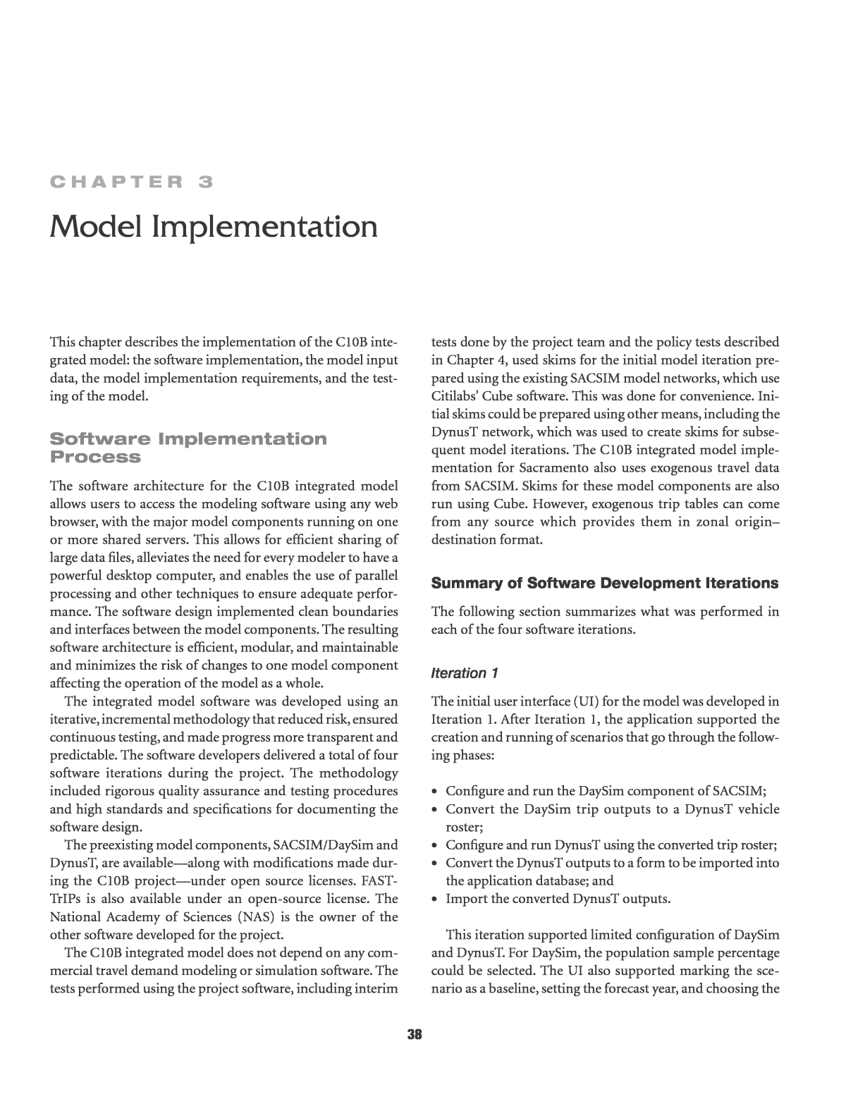
43 results that result from integrating SACSIM with the DynusT assignment procedures. ⢠Determine whether or not the SACSIM/DynusT procedure is iterating to closure. Is it getting closer to or further away from observed transit volumes, traffic volumes, and traffic speeds? ⢠Measure the reasonableness of the traffic and transit assign- ment results. Of course, the reasonableness of the assign- ment results is somewhat dependent on the impact that the SACSIM/DynusT procedure has on SACSIM. All testing was conducted for the 2005 base year using the same socioeconomic, land use, and network data used by SACOG for SACSIM. In addition, observed traffic and transit data used for the validation of SACSIM were available. The proof-of-concept testing consisted of comparisons of various C10B integrated model and SACSIM results and checks of model convergence. The checks are described in the remainder of this section. A separate process, used to test the integration between DynusT and MOVES, is described at the end of this section. Comparisons Between the C10B Integrated Model and SACSIM Results Table 3.1 compares the number of personal tours in the C10B integrated model with those generated in SACSIM. Overall, the C10B model predicts 3.8 million tours, compared with 3.5 million tours simulated by SACSIM. The C10B model predicts 7% more drive alone tours, 2% more shared ride 2 tours, and 27% more 3+ tours. For other tours, such as walk, the C10B model predicts a modest decrease. Nonauto tours are higher in the C10B model. Table 3.2 breaks down the num- ber of transit tours by purpose. Average travel times by tour purpose in SACSIM and the C10B integrated model are shown in Table 3.3. Most of the differences are minor, with the average travel time being 11.4 min in both models. Table 3.4 shows average model output speeds by facility type and time period for the integrated model and the origi- nal SACSIM implementation. For every facility type and time period, DTA speeds are lower than the SACSIM speeds. DynusT daily speeds on freeways are 10 mph lower than SACSIM, while the difference on arterials is 8 mph. Table 3.5 shows the VMT by facility type and peak period. Static and dynamic assignments produce approximately the same daily VMT, but the breakdown is different. The most notable differenceâwhich is evident across all time periodsâ is the split between freeways and arterials. SACSIM in all time periods except evening has an even split between arterials and freeway links. In contrast, DynusT consistently assigns more flow on arterials than on freeway links. Table 3.6 shows the total modeled volume for the screenlines used for calibrating and validating the SACSIM model. Fig- ure 3.1 shows the screenline locations. Screenlines 1, 2, 3, and 4 cover important streets to and from downtown Sacramento; Screenlines 5 and 16 represent important bridges along the American River to the north of downtown Sacramento. Table 3.1. Number of Tours Generated in C10B and SACSIM Models Tour Mode C10B Integrated Model SACSIM Drive to Transit 5,487 5,596 Walk to Transit 30,326 43,923 School Bus 77,888 73,874 Shared Ride 3+ 1,059,727 823,039 Shared Ride 2 918,167 894,269 Drive Alone 1,497,482 1,408,492 Bike 40,994 61,482 Walk 178,689 206,090 Total 3,808,760 3,516,765 Table 3.2. Transit Tours by Purpose Tour Purpose C10B Integrated Model SACSIM Work 13,991 23,381 School 11,671 13,547 Escort 191 299 Personal Business 4,401 5,894 Shopping 1,332 1,468 Meal 1,679 2,184 Social/Recreational 2,548 2,746 Total 35,813 49,519 Table 3.3. Average Travel Time by Purpose, in Minutes Tour Purpose C10B Integrated Model SACSIM Work 15.8 16.1 School 12.5 13.0 Escort 10.6 8.4 Personal Business 10.5 10.9 Shopping 9.0 9.5 Meal 9.8 10.3 Social/Recreational 11.4 11.7 All Trips 11.4 11.4
44 Table 3.4. Comparison of Model Output Speeds Facility Type A.M. Peak Midday P.M. Peak Evening Daily Integrated Model Average Speeds (VMT/VHT) Freeway 39 48 38 45 43 Ramp 16 22 15 15 17 Arterial 24 25 21 24 24 HOV 58 49 58 47 50 Highway 33 34 26 36 33 SACSIM Average Speeds (VMT/VHT) Freeway 49 55 47 58 52 Ramp 25 27 24 27 26 Arterial 31 34 29 35 32 HOV 58 55 55 56 56 Highway 48 51 48 51 49 Note: VMT = vehicle-miles traveled; VHT = vehicle-hours traveled; HOV = high- occupancy vehicle. Table 3.5. Comparison of Model Output VMT Facility Type A.M. Peak Midday P.M. Peak Evening Daily C10B Integrated Model VMT Freeway 3,934,323 5,987,745 4,270,989 7,497,977 21,691,035 Ramp 253,170 376,998 288,706 489,409 1,408,284 Arterial 5,233,265 7,239,180 5,975,892 9,240,086 27,688,425 HOV 112,722 284,612 131,938 357,861 887,135 Highway 516,170 710,475 522,036 962,862 2,711,544 Total 10,049,650 14,599,010 11,189,561 18,548,195 54,386,423 SACSIM VMT Freeway 4,782,757 7,883,803 5,420,393 7,473,081 25,560,034 Ramp 310,412 437,844 325,040 397,128 1,470,424 Arterial 4,794,666 7,037,120 5,544,741 6,609,607 23,986,134 HOV 116,877 411,016 180,083 449,572 1,157,548 Highway 411,777 741,872 494,702 686,710 2,335,061 Total 10,416,489 16,511,655 11,964,959 15,616,098 54,509,201 Note: VMT = vehicle-miles traveled.
45 Table 3.6. Screenline Volume Comparison Screenline A.M. Peak P.M. Peak Midday Evening Daily Integrated Model Volumes 1 26,956 44,197 34,483 55,411 161,047 2 27,251 37,030 34,801 41,065 140,147 3 47,777 68,535 47,002 71,227 234,541 4 15,493 23,192 17,195 26,701 82,581 5 89,291 113,284 88,984 162,534 454,093 16 97,188 136,992 99,614 179,911 513,705 Total 303,956 423,230 322,079 536,849 1,586,114 SACSIM Modeled Volumes 1 17,221 30,675 22,617 25,538 96,050 2 23,164 36,583 26,638 28,925 115,310 3 32,625 51,042 34,567 45,094 163,328 4 15,020 21,185 14,737 17,658 68,601 5 97,733 148,488 109,737 151,318 507,276 16 99,427 150,808 108,226 146,321 504,783 Total 285,190 438,781 316,522 414,854 1,455,348 DynusT Network Screen Line 0 1 2 3 4 5 16 Figure 3.1. Screenlines for SACSIM model.
46 Table 3.7 presents the percentage difference between the modeled volumes on the screenlines for the C10B integrated and SACSIM models, with SACSIM serving as the base. The DTA module of the integrated model results in about 9% additional volume through all the screenlines. Differences related to screenlines 5 and 16, which correspond to bridge crossings along the American River, are less pronounced compared with the rest of the screenlines, which correspond to highway streets. Also, in all time periods except evening, the total screenline volume does not differ that much although its distribution among individual screenlines does. In general DTA volumes are not expected to match static assignment volumes unless there is little if any congestion. The more con- gestion there is, the more the volumes and travel times will differ between the two assignment methodologies. Convergence Checks Equilibrium between demand and supply is a fundamental economic principle that is applied in many disciplines and has been followed by transportation practitioners for decades. When dealing with advanced demand-side models, both static and dynamic traffic assignment models are integrated using the same equilibrium principles and techniques applied to traditional demand models. Equilibrium ensures the consistency and stability of the overall model system and optimality at the supply level. At equilibrium, the expected level of service (LOS) used by trav- elers to make decisions in the demand model is the same as the realized LOS in the supply model that assigns travelersâ patterns to the network and determines congestion. Inconsis- tency between the expected and realized LOS, as in reality, provides an incentive to travelers to change their short- or long-term travel behavior, which can include departure time or activity location changes that can cascade to longer-term location changes. In state-of-the-practice four-step models, the equilibration between demand and supply is achieved by performing a number of âbig loopâ iterations between demand (i.e., trip distribution and mode choice) and static assignment. A mea- sure frequently used for model system convergence in four- step models is the absolute average percentage change in zone-to-zone trips between two successive big loop iterations. This same measure can be applied in advanced activity-based DTA models such as the C10B integrated model. Mathemati- cally, the absolute average percentage change is defined as â â â â â 1 1 q q q ijt k ijt k ijt ijt k ijt where qkijt is the number of trips between O-D pair ij at time interval t and for big loop iteration k. When the entire model system is at equilibrium, travelersâ decisions in the demand model are stable. Overall stability is translated as stability in location, time of day, tour, and trip stability between zones. As a result, in an equilibrated model, the difference between the number of trips qkijt between zone i and zone j at time interval t in big loop iteration k and the number of trips between the same zone in the previous big loop iteration k-1, qk-1ijt , is minimal and bounded from the bottom only by the inherent randomness in travel demand and network supply microsimulation. Unlike four-step models, which exhibit a great degree of determinism resulting from modeling aggregate quantities and using static assignment, activity-based and DTA models are by design inherently random. As a result, these advanced models do not converge to a single point; rather, they contain a level of noise in their results that needs to be taken into account in scenario evaluation. Even though noise in model results can complicate scenario evaluation by requiring more runs and careful comparison, it is not a drawback of the more advanced models and can be seen as a more realistic representation of the transportation systemâwhich is inherently stochastic. In the C10B integrated model implementation, for each big loop iteration the travelersâ choices in the demand model are calculated once based on the transportation LOS provided by DynusT in the previous iteration. In contrast, multiple itera- tions of DynusT are run as part of each big loop iteration to allow travelers to adjust their route choices to avoid conges- tion and make optimal decisions to minimize generalized travel time. The convergence of the DTA model is determined by the relative gap measure. Its functional form is similar to the computation shown in the preceding equation, which determines the overall system convergence defined in this sec- tion and measures the degree of optimality and stability in travelersâ LOS in percentage terms. In C10B integrated model implementation, the DTA model comprises the majority of the model run time. Table 3.7. Percentage Differences Between C10B and SACSIM Model Screenline Volumes Screenline A.M. Peak P.M. Peak Midday Evening Daily 1 57% 44% 52% 117% 68% 2 18% 1% 31% 42% 22% 3 46% 34% 36% 58% 44% 4 3% 9% 17% 51% 20% 5 -9% -24% -19% 7% -10% 16 -2% -9% -8% 23% 2% Total 57% 44% 52% 117% 68%
47 Therefore, reducing the number of iterations of the DTA model without severely affecting the convergence of the over- all model system became a priority. Specifically, it was found that the DTA zone-to-zone LOS (represented by the time- dependent skim matrices) converges faster than travelersâ travel times. Individual travel times in DynusT in the Sacra- mento implementation converge after 20 or 30 iterations to a relative gap significantly less than 10%, whereas zone-to-zone travel times (skims) converge to the same level much faster, often in 10 iterations. Given that only skim travel times and not individual travel times are used as an input to the demand model, it was decided to apply the DTA model iteratively 10 times in each big loop iteration, cutting the overall run time in half compared with the 20 or even 30 iterations of the DTA model. Figure 3.2 and Figure 3.3 show some of the quantitative results on which the conclusions are based. Figure 3.2 shows a histogram of differences in skim travel times in the Figure 3.2. Differences in mean travel times between Iterations 10 and 20, 8:00 a.m. Figure 3.3. Differences in mean travel times between Iterations 20 and 21, 8:00 a.m.
48 Sacramento DynusT implementation between Iterations 10 and 20. The average skim values for the two iterations are the same while the standard deviation of the differences is 1.5 min. Interestingly, as shown in Figure 3.3, the standard deviation between the consecutive Iterations 20 and 21, which can be considered mostly noise, is 1.2 min, which is very close to the reported difference between Iterations 10 and 20. Additional quantitative investigations with the DTA skims after 30 iterations established the finding that the skims converge much faster than the overall DTA application as measured by the relative gap measure. As a consequence, the study team decided to run the DTA model in 10 itera- tions, saving time without compromising the quality of the skim tables. The overall model system convergence in the C10B inte- grated model, as is always the case in deterministic four-step applications, is driven by the properties of the demand and supply models and cannot be lower than the level of conver- gence in the supply model. More specifically, model system convergence is bounded at the bottom by the convergence achieved by the DTA supply model. In the C10B integrated model, several big loop iterations are run between supply and demand to determine which combination of big loop and DTA iterations yields the best results, taking into account run time. It was specifically found that after running three big loop iterations, each of which consists of 10 supply iterations, the systemwide model convergence reached a plateau that did not improve with more iterations. It was found that three big loop iterations result in a systemwide convergence level that is between 10% and 15%, meaning that on average the number of trips between each zone pair changes by no more than 10% to 15% between successive big loop itera- tions, which is approximately what can be achieved by DynusT in 10 iterations in the Sacramento implementation. This conclusion is also supported by the skim comparison shown in subsequent sections and by examining screenline flow fluctuation within a DTA run and between big loop iterations. Screenline Volume Stability Table 3.8 presents the screenline volumes from big loop Iterations 1 and 3 while Table 3.9 displays the percentage differences between them. Overall the total volume across the screenlines in Iteration 3 has been reduced by 2%. How- ever, given the noise in DTA results, this number may imply that the difference is even smaller. Individual screenline vol- umes can differ significantly, up to 18%, especially in the a.m. peak period. Table 3.8. Screenline Volume Comparison for Big Loops 1 and 3 Screenline A.M. Peak P.M. Peak Midday Evening Daily Big Loop 1 Screenline Volumes 1 26,956 44,197 34,483 55,411 161,047 2 27,251 37,030 34,801 41,065 140,147 3 47,777 68,535 47,002 71,227 234,541 4 15,493 23,192 17,195 26,701 82,581 5 89,291 113,284 88,984 162,534 454,093 16 97,188 136,992 99,614 179,911 513,705 Total 303,956 423,230 322,079 536,849 1,586,114 Big Loop 3 Screenline Volumes 1 26,784 42,935 35,130 55,355 160,204 2 22,993 33,297 35,886 40,301 132,477 3 43,903 63,686 47,935 71,443 226,967 4 13,176 19,693 19,336 25,928 78,133 5 72,895 117,255 93,944 167,307 451,401 16 88,352 132,931 98,851 181,942 502,076 Total 268,103 409,797 331,082 542,276 1,551,258
49 DTA Volume Stability The screenline volumes after 10, 20, and 30 iterations of DynusT were compared to determine the stability of the flows in differ- ent stages of execution. Tables 3.10aâc show the comparisons between the screenline volumes for model runs for different numbers of iterations. It was found that DTA volumes stabilize after the 10th iteration with little change in subsequent itera- tions that is not attributable to simulation noise. Specifically, it was found that the overall change in volumes between Iteration 10 and Iteration 30 is less than 2%, with individual screenlines showing somewhat greater fluctuations. Comparatively, there is an overall change of about 1% between Iterations 20 and 30 with a high level of DTA simulation noise when comparing Iterations 20 and 21. For some analyses, it may be necessary to Table 3.9. Percentage Differences Between Screenline Volumes for Big Loops 1 and 3 Screenline A.M. Peak P.M. Peak Midday Evening Daily 1 -1% -3% 2% 0% -1% 2 -16% -10% 3% -2% -5% 3 -8% -7% 2% 0% -3% 4 -15% -15% 12% -3% -5% 5 -18% 4% 6% 3% -1% 16 -9% -3% -1% 1% -2% Total -12% -3% 3% 1% -2% Table 3.10a. Screenline Volume Comparisons for Different Numbers of Iterations: 10 and 30 Screen- line A.M. Peak P.M. Peak Midday Evening Daily Iteration 10 Volumes 1 24,001 42,194 34,424 54,217 154,836 2 19,355 30,610 31,287 38,920 120,172 3 39,913 63,408 44,838 75,056 223,215 4 11,888 21,657 15,764 26,877 76,186 5 73,223 126,804 88,230 171,990 460,247 16 85,426 144,697 100,383 191,249 521,755 Total 253,806 429,370 314,926 558,309 1,556,411 Iteration 30 Volumes 1 23,205 39,870 31,580 54,420 149,075 2 17,539 27,711 28,289 34,062 107,601 3 39,038 61,129 44,368 70,570 215,105 4 11,401 20,865 17,320 28,823 78,409 5 73,283 127,601 90,621 166,699 458,204 16 85,708 143,424 98,838 193,128 521,098 Total 250,174 420,600 311,016 547,702 1,529,492 Percentage DifferencesâIterations 10 and 30 1 -3% -6% -8% 0% -4% 2 -9% -9% -10% -12% -10% 3 -2% -4% -1% -6% -4% 4 -4% -4% 10% 7% 3% 5 0% 1% 3% -3% 0% 16 0% -1% -2% 1% 0% Total -1% -2% -1% -2% -2% Table 3.10b. Screenline Volume Comparisons for Different Numbers of Iterations: 10 and 20 Screen- line A.M. Peak P.M. Peak Midday Evening Daily Iteration 10 Volumes 1 24,001 42,194 34,424 54,217 154,836 2 19,355 30,610 31,287 38,920 120,172 3 39,913 63,408 44,838 75,056 223,215 4 11,888 21,657 15,764 26,877 76,186 5 73,223 126,804 88,230 171,990 460,247 16 85,426 144,697 100,383 191,249 521,755 Total 253,806 429,370 314,926 558,309 1,556,411 Iteration 20 Volumes 1 23,525 40,253 33,016 54,757 151,551 2 18,050 28,301 29,270 35,630 111,251 3 39,576 61,933 44,372 72,547 218,428 4 11,697 20,986 17,610 27,757 78,050 5 73,547 127,414 90,499 168,555 460,015 16 85,738 143,437 99,221 192,014 520,410 Total 252,133 422,324 313,988 551,260 1,539,705 Percentage DifferencesâIterations 10 and 20 1 -2% -5% -4% 1% -2% 2 -7% -8% -6% -8% -7% 3 -1% -2% -1% -3% -2% 4 -2% -3% 12% 3% 2% 5 0% 0% 3% -2% 0% 16 0% -1% -1% 0% 0% Total -1% -2% 0% -1% -1%
50 Table 3.10c. Screenline Volume Comparisons for Different Numbers of Iterations: 20 and 21 Screen- line A.M. Peak P.M. Peak Midday Evening Daily Iteration 20 Volumes 1 23,525 40,253 33,016 54,757 151,551 2 18,050 28,301 29,270 35,630 111,251 3 39,576 61,933 44,372 72,547 218,428 4 11,697 20,986 17,610 27,757 78,050 5 73,547 127,414 90,499 168,555 460,015 16 85,738 143,437 99,221 192,014 520,410 Total 252,133 422,324 313,988 551,260 1,539,705 Iteration 21 Volumes 1 25,023 43,945 35,562 57,936 162,466 2 22,073 34,487 32,985 41,127 130,672 3 41,602 65,287 46,837 74,346 228,072 4 12,064 21,928 17,033 29,564 80,589 5 75,788 131,773 92,892 171,272 471,725 16 86,188 143,409 98,522 194,278 522,397 Total 262,738 440,829 323,831 568,523 1,595,921 Percentage DifferencesâIterations 20 and 21 1 6% 9% 8% 6% 7% 2 22% 22% 13% 15% 17% 3 5% 5% 6% 2% 4% 4 3% 4% -3% 7% 3% 5 3% 3% 3% 2% 3% 16 1% 0% -1% 1% 0% Total 4% 4% 3% 3% 4% run the DTA model for more than 10 iterations to ensure that individual link DTA volumes are stable enough; but for more aggregate analyses, 10 iterations appear to be sufficient. Comparisons Between Big Loop Runs There is a small percentage decrease, 5% or less, in the average zone-to-zone LOS between big loop Iterations 1 and 3. This decrease in average skim travel times is more prominent in the peak periods and less pronounced in the off-peak periods, which may be attributed to travelers changing their departure times to avoid congestion or selecting destinations which can be reached with less delay. For example, as shown in Figure 3.4, the average skim travel times for big loop Iteration 3 at 5:00 p.m. are 1.7 min lower than skim travel times in big loop Iteration 1. It should be noted that the difference in average skim values varies by 30-min time period. For example, between 5:00 p.m. and 7:00 p.m. the average travel time decrease is about 1.5 min; in the hour 4:00 p.m. to 5:00 p.m. (see Figure 3.5), average skim travel times did not change significantly, with the period from 16:00 to 16:30 showing a slight increase in travel times of 0.4 min, an indication that drivers might be shifting their departure times to avoid congestion. Interestingly, not all originâdestination pairs registered a decrease in skim travel times between big loop iterations; some of them showed a mod- erate increase which was offset by the larger number of pairs that exhibited a decrease. Comparison of Static and Dynamic Skims Activity-based models so far have used static highway assign- ment models that provide average LOS for multihour peak time periods. One of the main objectives of the C10B research is to take advantage of DTA modelsâ simulation of driversâ route choices and interactions with other drivers and their ability to provide more realistic travel times at finer time resolutions. Despite the differences in the static and dynamic network assignment models, the study team found that, on average, the static and dynamic zone-to-zone travel times do not differ although individual zone-to-zone values can differ significantly. This is an encouraging research result because it increases the compatibility and substitutability of DTA models in an activity- based model setup that already uses static assignment. Analyzing the differences between the static and dynamic skims is important in developing the theoretical framework to be used in integrating activity-based models and DTA models, given that the activity-based model interacts with the DTA model only through the skims. Figure 3.6 is a scatterplot that shows static skim travel times versus dynamic skim travel times. For the C10B integrated model, dynamic skim travel times are calculated every 30 min, but in this plot dynamic times are computed for the time period from 3:00 p.m. to 6:00 p.m., which coincides with the p.m. peak period used in SACSIM. In the scatterplot, there are more than 2 million zone-to-zone data points shown. Instead of showing the points themselves as in a regular scatterplot, the density of the points is displayed using the colorbar on the right of the figure. Points change colors based on the loga- rithm of the density. A red color indicates that there are 10,000 (104) points in a particular location on the graph. Most but not all of the outliers in the lower part of the figure are due to differences in the zone connector structures. The clustering of points around the diagonal means that, on average, there is little difference between the static and dynamic skims. Had the average skim values been different, substantial recalibration of SACSIM would have been necessary. (It is important to note that this finding applies only to skim values and not to indi- vidual vehicle travel times, which may differ significantly.)
51 Figure 3.4. Skim differences between big loop Iterations 1 and 3, 5:00 p.m. Figure 3.5. Skim differences between big loop Iterations 1 and 3, 4:00 p.m.
52 Figure 3.6. Static skim travel times versus dynamic skim travel times, from 3:00 p.m. to 6:00 p.m. Figure 3.7. Differences between static and dynamic travel times, a.m. peak period. Figure 3.7 is a histogram of the differences of individual zone-to-zone travel times between the static and the dynamic network models in the a.m. peak period. It is interesting to note that the average difference is 0.9 minâabout a 2% dif- ference, with the average skim value of about 45 min. Figure 3.8 shows the distribution of static and dynamic travel times in the a.m. peak period. Again the average static and dynamic skim travel times are very close. Rather than showing the data aggregated into multihour periods that cor- respond to the static assignments, the figure shows the DTA results for a small number of 30-min intervals from 7:30 a.m. to 9:00 a.m. Average skim travel times range from 44.3 min to 47.9 min, while the average a.m. peak static travel time is 45.5 min.
53 testing of the Dynust-MOVeS Integration This section summarizes the set-up, data preparation, and CO2 emissions results for a brief sample case to illustrate the MOVES-DynusT integration process. During the prepara- tion of this sample case study, MOVES2010a was the latest available version and was used for calculating CO2 emissions with DynusT-based travel activity data. The study team observed no changes in CO2 emissions model outputs between MOVES2010a and MOVES2010b. Therefore, the discussions presented in this section should remain valid if MOVES2010b is used in place of MOVES2010a. Network Descriptions and Scenario Setup The proposed MOVES-DynusT integration framework was carried out and examined with a downtown network (see Figure 3.9) in Sacramento, California, where State Highway 50 traverses the center of the network and Interstate 80 and State Highway 99 intersect Highway 50 on the west- and east-side of the network, respectively. This roadway network as repre- sented in DynusT consists of 437 nodes and 768 links. The simulation was performed for a morning peak time period (between 6:00 a.m. and 10:00 a.m.) on a weekday in February 2009. As a hypothetical case study, a total of 66,150 vehicles were generated in this time period and the hourly travel demand distributions were 10%, 19%, 28%, and 43%, with a much higher demand in the last hour (9:00 a.m. to 10:00 a.m.). The surge of demand was intended to allow the examination of how MOVES emissions estimation is affected by congestion level. The fleet mix was set to consist of 90% passenger vehi- cles and 10% heavy-duty vehicles. Two scenarios were considered: a baseline scenario and an intersection improvement scenario. The intersection Figure 3.8. Static and dynamic skim differences, a.m. peak period.
54 improvement scenario included off-ramp capacity expansion and a downstream intersection signal retiming strategy to alleviate the westbound traffic congestion caused by the off- ramp traffic spillback. Both the baseline and improvement scenarios were modeled in DynusT to generate travel activity data, such as detailed vehicle trajectories, speed, and hourly VMT changes (see Figure 3.10). These data were then pro- cessed to populate data tables for MOVES project-scale mod- eling runs. Note that hours 1 through 4 represent each hour during the morning peak from 6:00 to 10:00 a.m. For the three key MOVES input data tables (i.e., âLinks,â âLinkSourceTypes,â and âOpmodeDistributionâ), external quality checking was performed to ensure data completeness and consistency. Specifically, the following checks were con- ducted on the DynusT-based MOVES input data for CO2 emissions modeling (these checks are typically related to common areas in which project-scale MOVES input data may have completeness and consistency issues): ⢠For each hour, checked if there were links with missing traffic volume data in the âLinksâ data table; ⢠For each hour, checked data completeness in the â LinkSourceTypesâ and âOpmodeDistributionâ input tables; ensured that, for each link with nonzero traffic volume, there were source type distribution data in the Figure 3.10. Variation in VMT of all source types from DynusT simulation by hour for baseline and intersection improvement scenarios. Figure 3.9. Illustration of case study roadway network in DynusT. Map data © Google. Source: DynusT simulation.
55 Table 3.11. Comparison of Travel Activity Estimates Between Baseline and Improvement Scenarios Activity Baseline Improvement Change VHT (hours) 3,569 3,130 -12.3% VMT (miles) 139,730 136,247 -2.5% Total stop time (hours) 550 338 -38.5% âLinkSourceTypesâ table and operating mode distribu- tion data (by source type) in the âOpmodeDistributionâ table; and ⢠Ensured that the operating mode data were processed appropriately (based on vehicle speed and VSP data) and fractions data were correctly assigned to the corresponding operating mode bins in MOVES. Travel Activity and CO2 Emissions Estimates For the two scenarios in this case study, the general patterns of the travel activity and CO2 emissions estimates from the MOVES-DynusT simulations were evaluated. The compari- son focused on assessing whether CO2 emissions estimates and the corresponding travel activity changes were consistent with the use of the MOVES-DynusT integration framework and data processing approaches. Baseline Versus Improvement Scenario Compared with the baseline condition, traffic operation in the improvement scenario was improved. As shown in Table 3.11, the off-ramp capacity increase and signal timing optimization resulted in reductions in vehicle-miles traveled (VMT) and vehicle-hours traveled (VHT). Significant improvement in total vehicle stop time at signals (in hours) was also observed. As shown in Figure 3.11, speed space-time contour dia- grams were used to compare temporal variation in conges- tion levels between the baseline and the improvement scenarios. A space-time contour diagram typically shows how speed changes by time (in the x-axis) along a roadway segment (dis- tance in the y-axis). For example, Figure 3.11 suggests that, in general, higher vehicle speeds were observed in the improve- ment scenario (right), relative to the baseline scenario (left), especially in the upstream traffic during Hour 4 (9:00 a.m. to 10:00 a.m.). The operating mode distributions, which are directly related to emissions estimation in MOVES, were compared between the baseline and the improvement scenarios. Fig- ure 3.12 shows the comparison results for Hour 1 (6:00 a.m. to 7:00 a.m.) data, in which operating mode distributions are aggregated into three speed ranges: low (0 to 25 mph), medium (25 to 50 mph) and high (>50 mph). The pie charts indicate that more operating modes were shifted from medium- to high-speed categories. Accordingly, greenhouse gas emissions are expected to be lower in the improvement scenario due to better energy efficiency associated with higher-speed oper- ating modes. Hour-by-hour comparisons (see Figure 3.13 and Fig- ure 3.14) suggest that (a) the overall CO2 equivalent (referred as CO2E) emissions were reduced across source types in the improvement scenario; (b) there were larger percentage reductions of CO2E emissions than reductions in VMT; and (c) for some hours, reduced CO2E emissions were observed in the improvement scenario despite increased VMT over the Figure 3.11. Comparison of speeds between baseline (left) and improvement (right) scenarios.
56 Figure 3.12. Comparison of operating mode distributions between scenarios from 6:00 a.m. to 7:00 a.m. Figure 3.13. Percent change in VMT: Improvement versus baseline scenario. Note: LDV = light-duty vehicle; LDT = light-duty truck; HDT = heavy-duty truck. Figure 3.14. Percent change in CO2E emissions: Improvement versus baseline scenario. Note: LDV = light-duty vehicle; LDT = light-duty truck; HDT = heavy-duty truck.
57 baseline. These comparison results indicated that, in addition to VMT changes, the shift in operating mode distributions (reduced stop time and improved travel speed) were associ- ated with the CO2E emissions reductions. Default Drive Schedules Versus Local Operating Mode Distributions Under the MOVES-DynusT integration framework, operat- ing mode distributions used as the major inputs in MOVES are calculated based on DynusT simulation data. This approach is theoretically sound and presumably pro- duces more reasonable emissions estimates than using the MOVES default drive schedule or average speed data. Note that using operating mode distributions to develop emis- sions estimates in MOVES reflects a modeling approach based on local travel activity information. Alternatively, MOVES allows use of its default drive schedule (second-by- second speed) data for calculating emissions, which requires relatively less modeling effort. The team was interested in evaluating how emissions estimates differ when using MOVES default drive schedules and when using user- supplied operating mode distributions (e.g., generated from DynusT-based activity data). To set up the comparison, the same baseline scenario was used as presented previously in the brief case study; MOVES was run separately with (a) link average speeds (i.e., using MOVES default drive schedules) and (b) user-supplied oper- ating mode distributions developed in DynusT. Figure 3.15 illustrates the hour-by-hour CO2E emissions comparison results. Note that in this comparison, the two approaches (the default drive schedule approach and the operating mode dis- tribution approach) were conducted using the same VMT data generated from the DynusT baseline simulation. As discussed earlier, VMT in the baseline scenario increased and the sample network became more congested from Hour 1 to Hour 4. The emissions results for the first 3 h show a con- sistent pattern (i.e., using MOVES default drive schedules yields up to 37% higher CO2E emissions than using the local- ized operating mode distributions generated by DynusT). However, the comparison results in Hour 4 indicate a reversed pattern, in which lower CO2E emissions were estimated under a more congested traffic condition with the default drive schedule modeling approach. Further investigation found a problem with MOVES itself: zero emissions were being estimated for heavy-duty vehicles traveling on links with average speeds below 5.8 mph, which led to inaccurate emissions estimates in highly congested conditions. This meant that, when default drive schedules were used as activity inputs, MOVES provided no emissions estimates for heavy-duty vehicles for links with an average speed lower than 5.8 mph. Similarly, emissions were not gen- erated for light-duty vehicles when average link speed was below 2.5 mph (see Table 3.12). Travel activities of low speeds are typically associated with high pollutant emissions. Hence, using the default drive schedule approach in MOVES, which omitted emissions estimates associated with low- speed links, resulted in underestimated emissions. Consequently, it is noteworthy that under a highly con- gested condition, using localized operating mode distribution Note: LDV = light-duty vehicle; LDT = light-duty truck; HDT = heavy-duty truck. Figure 3.15. Percent difference in CO2E emissions by hour and source type: MOVES default drive schedule approach versus user-supplied operating mode distribution approach.
58 data is of particular importance to produce more reasonable emissions results. Discussion Through a brief case study, it was verified that the MOVES- DynusT integration framework and data processing approach can take advantage of local operating mode distribution data, produce reasonable and informative CO2 emissions results, and reflect simulated impacts of assumed analysis strategies. The preliminary results of analysis suggest that, using DynusT-based travel data and MOVES project-scale model- ing functions, CO2 emissions changes can be reasonably modeled with the shift in operating mode distributions. The case study also indicated the importance of using the local- ized operating mode, instead of MOVES default drive sched- ule data, for generating emissions estimates especially under highly congested conditions. Table 3.12. MOVES Allowable Average Speed Input Range for Project-Level Analysis by Source Type SourceTypeID SourceTypeName Minimum Speed (mph) Maximum Speed (mph) 11 Motorcycle 2.5 73.8 21 Passenger Car 2.5 73.8 31 Passenger Truck 2.5 73.8 32 Light Commercial Truck 2.5 73.8 41 Intercity Bus 4.6 72.8 42 Transit Bus 15.0 72.8 43 School Bus 15.0 72.8 51 Refuse Truck 2.2 71.7 52 Single Unit Short-haul Truck 4.6 72.8 53 Single Unit Long-haul Truck 4.6 72.8 54 Motor Home 4.6 72.8 61 Combination Short-haul Truck 5.8 71.7 62 Combination Long-haul Truck 5.8 71.7 Source: U.S. Environmental Protection Agency (2012).