


Below is the uncorrected machine-read text of this chapter, intended to provide our own search engines and external engines with highly rich, chapter-representative searchable text of each book. Because it is UNCORRECTED material, please consider the following text as a useful but insufficient proxy for the authoritative book pages.
435 A p p e n d i x F ABC Sample Design Calculations Three design examples are presented in this appendix, as follows: ⢠Sample Calculation 1: Decked Steel Girder Design for ABC ⢠Sample Calculation 2: Decked Precast Prestressed Concrete Girder Design for ABC ⢠Sample Calculation 3: Precast Pier Design for ABC The design examples illustrate the design steps involved in the ABC design process as given in the breakdown below. The ABC design philosophy and design criteria have been described. Annotations have been used for the purpose of providing explanation of the design steps. LRFD code references have also been included to guide the reader. Sample Calculation 1: Decked Steel Girder Design for ABC General: 1. Introduction 2. Design Philosophy 3. Design Criteria 4. Material Properties 5. Load Combinations Girder Design: 6. Beam Section Properties 7. Permanent Loads 8. Precast Lifting Weight 9. Live Load Distribution Factors 10. Load Results 11. Flexural Strength 12. Flexural Strength Checks 13. Flexural Service Checks 14. Shear Strength 15. Fatigue Limit States 16. Bearing Stiffeners 17. Shear Connectors Deck Design: 18. Slab Properties 19. Permanent Loads 20. Live Loads
436 21. Load Results 22. Flexural Strength Capacity Check 23. Longitudinal Deck Reinforcing Design 24. Design Checks 25. Deck Overhang Design Continuity Design: 26. Compression Splice 27. Closure Pour Design Sample Calculation 2: Decked Precast Prestressed Concrete girder Design for ABC General: 1. Introduction 2. Design Philosophy 3. Design Criteria Girder Design: 4. Beam Section 5. Material Properties 6. Permanent Loads 7. Precast Lifting Weight 8. Live Load 9. Prestress Properties 10. Prestress Losses 11. Concrete Stresses 12. Flexural Strength 13. Shear Strength 14. Splitting Resistance 15. Camber and Deflections 16. Negative Moment Flexural Strength Sample Calculation 3a: Precast Pier Design for ABC (70â Span Straddle Bent) 1. Bent Cap Loading 2. Bent Cap Flexural Design 3. Bent Cap Shear and Torsion Design 4. Column / Drilled Shaft Loading and Design 5. Precast Component Design Sample Calculation 3b: Precast Pier Design for ABC (70â Span Conventional Pier) 1. Bent Cap Loading 2. Bent Cap Flexural Design 3. Bent Cap Shear and Torsion Design 4. Column / Drilled Shaft Loading and Design 5. Precast Component Design
437 ABC SAMPLE CALCULATION â 1 Decked Steel Girder Design for ABC
438 This document shows the procedure for the design of a steel girder bridge with precast deck elements for use in a rapid bridge replacement design. The procedure in this document employs Accelerated Bridge Construction (ABC) methods. This sample calculation is intended as an informational tool for the practicing bridge engineer. These calculations illustrate the procedure followed to develop a similar design but shall not be considered fully exhaustive. This sample calculation is based on the AASHTO LRFD Bridge Design Specifications (Fifth Edition with 2010 interims). References to the AASHTO LRFD Bridge Design Specifications are included throughout the design example. AASHTO references are presented in a dedicated column in the right margin of each page, immediately adjacent to the corresponding design procedure. An analysis of the superstructure was performed using structural modeling software. The design moments, shears, and reactions used in the design example are taken from the output, but their computation is not shown in the design example. Design member parameters: Deck Width: C. to C. Piers: Roadway Width: C. to C. Bearings Skew Angle: Bridge Length: Deck Thickness Stringer Haunch Thickness Stringer Weight Haunch Width Stringer Length Girder Spacing Average spacing of adjacent beams. This value is used so that effective deck width is not overestimated.
439 General: 1. Introduction 2. Design Philosophy 3. Design Criteria 4. Material Properties 5. Load Combinations Girder Design: 6. Beam Section Properties 7. Permanent Loads 8. Precast Lifting Weight 9. Live Load Distribution Factors 10. Load Results 11. Flexural Strength 12. Flexural Strength Checks 13. Flexural Service Checks 14. Shear Strength 15. Fatigue Limit States 16. Bearing Stiffeners 17. Shear Connectors Deck Design: 18. Slab Properties 19. Permanent Loads 20. Live Loads 21. Load Results 22. Flexural Strength Capacity Check 23. Longitudinal Deck Reinforcing Design 24. Design Checks 25. Deck Overhang Design Continuity Design: 26. Compression Splice 27. Closure Pour Design
440 The design of this superstructure system follows AASHTO LRFD and is based on a bridge of three even spans, with no skew. The bridge has two 14-foot lanes and two 8-foot shoulders, for a total roadway width of 44' from curb to curb. The out-to-out width of the bridge is 47'-2". The bridge deck is precast reinforced concrete with overhangs at the outermost girders. The longitudinal girders are placed as simply supported modules, and made continuous with connection plates and cast-in-place deck joints. The design of the continuity at the deck joint is addressed in final sections of this example. The cross-section consists of six modules. The interior modules are identical and consist of two steel girders and a 7'-10" precast composite deck slab. Exterior modules include two steel girders and a 7'-11" precast composite deck slab, with F-shape barriers. Grade 50 steel is used throughout, and the deck concrete has a compressive strength of 5,000 psi. The closure pour joints between the modules use Ultra High Performance Concrete with a strength of 21,000 psi. The following sections detail the design of the steel girders, including constructability checks, fatigue design for infinite fatigue lift (unless otherwise noted), and bearing stiffener design. The diaphragms are not designed in detail. A brief deck design is also included, with focus on the necessary checks for this type of modular superstructure. Tips for reading this Design Example: This calculation was prepared with Mathcad version 14. Mathcad is a computational aide for the practicing engineer. It allows for repetitive calculations in a clear, understandable and presentable fashion. Other computational aides may be used in lieu of Mathcad. Mathcad is not a design software. Mathcad executes user mathematical and simple logic commands. Example 1: User inputs are noted with dark shaded boxes. Shading of boxes allows the user to easily find the location of a desired variable. Given that equations are written in mathcad in the same fashion as they are on paper, except that they are interactive, shading input cells allows the user to quickly locate inputs amongst other data on screen. Units are user inputs. Height of Structure: Example 2: Equations are typed directly into the workspace. Mathcad then reads the operators and executes the calculations. Panels are 2.5 ft Example 3: If Statements are an important operator that allow for the user to dictate a future value with given parameters. They are marked by a solid bar and operate with the use of program specific logic commands.
441 Operator offers discount per volume of panels Example 4: True or False Verification Statements are an important operator that allow for the user to verify a system criteria that has been manually input. They are marked by lighter shading to make a distinction between the user inputs. True or false statements check a single or pairs of variables and return a Zero or One. Owner to proceed if discounts on retail below 60% The geometry of this superstructure uses modules consisting of two rolled steel girders supporting a segment of bridge deck cast along the girder lengths. It is assumed that the initial condition for the girders is simply supported under the weight of the cast deck. Each girder is assumed to carry half the weight of the precast deck. After the deck and girders are made composite, the barrier is added to the exterior modules. The barrier dead load is assumed to be evenly distributed between the two modules. Under the additional barrier dead load, the girders are again assumed to be simply supported. During transport, it is assumed that 28-day concrete strength has been reached in the deck and the deck is fully composite with the girders. The self-weight of the module during lifting and placement is assumed as evenly distributed to four pick points (two per girder). The modules are placed such that there is a bearing on each end and are again simply supported. The continuous span configuration, which includes two bearings per pier on either side of the UHPC joints, is analyzed for positive and negative bending and shear (using simple or refined methods). The negative bending moment above the pier is used to find the force couple for continuity design, between the compression plates at the bottom of the girders and the closure joint in the deck. The deck design utilizes the equivalent strip method. The first step for any bridge design is to establish the design criteria. The following is a summary of the primary design criteria for this design example: Governing Specifications: AASTHO LRFD Bridge Design Specifications (5th Edition with 2010 interims) Design Methodology: Load and Resistance Factor Design (LRFD) Live Load Requirements: HL-93 S3.6 Section Constraints: Upper limit on the weight of the modules, based on common lifting and transport capabilities without significantly increasing time and/or cost due to unconventional equipment or permits
442 Structural Steel Yield Strength: STable 6.4.1-1 Structural Steel Tensile Strength: STable 6.4.1-1 Concrete 28-day Compressive Strength: S5.4.2.1 Reinforcement Strength: S5.4.3 & S6.10.3.7 Steel Density: STable 3.5.1-1 Concrete Density: STable 3.5.1-1 Modulus of Elasticity - Steel: Modulus of Elasticity - Concrete: Modular Ratio: Future Wearing Surface Density: STable 3.5.1-1 Future Wearing Surface Thickness: (Assumed) The following load combinations will be used in this design example, in accordance with Table 3.4.1-1. Strength I = 1.25DC + 1.5DW + 1.75(LL+IM), where IM = 33% Strength III = 1.25DC + 1.5DW + 1.40WS Strength V = 1.25DC + 1.5DW + 1.35(LL+IM) + 0.40WS + 1.0WL, where IM = 33% Service I = 1.0DC + 1.0DW + 1.0(LL+IM) + 0.3WS + 1.0WL, where IM = 33% Service II = 1.0DC + 1.0DW + 1.3(LL+IM), where IM = 33% Fatigue I = 1.5(LL+IM), where IM = 15% Determine Beam Section Properties: Girder btf x ttf Top Flange Bottom Flange Dw x tw Web Girder Depth bbf x tbf
443 Check Flange Proportion Requirements Met: S 6.10.2.2 Properties for use when analyzing under beam self weight (steel only): Total steel area. Steel centroid from top. Calculate Iz: Moment of inertia about Z axis. Calculate Iy: Moment of inertia about Y axis. Calculate Ix: Moment of inertia about X axis.
444 Composite Section Properties (Uncracked Section - used for barrier dead load and live load positive bending): Determine composite slab and reinforcing properties Slab thickness assumes some sacrificial thickness; use: Total section depth Effective width. S 4.6.2.6.1 Transformed slab width as steel. Transformed slab moment of inertia about z axis as steel. Transformed slab area as steel. Slab reinforcement: (Use #5 @ 8" top, and #6 @ 8" bottom; additional bar for continuous segments of #6 @ 12") Typical Cross Section Cross Section Over Support ref from top of slab
445 Find composite section centroid: Centroid of steel from top of slab. Centroid of transformed composite section from top of slab. Calculate Transformed Iz for composite section: Transformed moment of inertia about the z axis. Calculate Transformed Iy for composite section: Transformed slab thickness. Transformed moment of inertia about y axis of slab. Transformed moment of inertia about the y axis (ignoring reinforcement). Calculate Transformed Ix for composite section: Transformed moment of inertia about the x axis. Results: Composite Section Properties (Uncracked Section - used for live load negative bending): Find composite section area and centroid: Centroid of transformed composite section from top of slab. Calculate Transformed Izneg for composite negative moment section: Transformed moment of inertia about the z axis.
446 Composite Section Properties (Cracked Section - used for live load negative bending): Find cracked section area and centroid: Find cracked section moments of inertia and section moduli: Phase 1: Steel girders are simply supported, and support their self-weight plus the weight of the slab. Steel girders in each module for this example are separated by three diaphragms - one at each bearing location, and one at midspan. Other module span configurations may require an increase or decrease in the number of diaphragms. Diaphragms: MC18x42.7 Thickness Conn. Plate Diaphragm Weight Width Conn. Plate Diaphragm Length Height Conn. Plate Equivalent distributed load from DC point loads: Interior Uniform Dead Load, Phase 1: Exterior Uniform Dead Load, Phase 1:
447 Moments due to Phase 1 DL: Shear due to Phase 1 DL: Phase 2: Steel girders are simply supported and composite with the deck slab, and support their self-weight plus the weight of the slab in addition to barriers on exterior modules. Barriers are assumed to be evenly distributed between the two exterior module girders. Barrier Area Barrier Weight Interior Dead Load, Phase 2: Exterior Dead Load, Phase 2: Moments due to Phase 2 DL: Shear due to Phase 2 DL: Phase 3: Girders are composite and have been made continuous. Utilities and future wearing surface are applied. Unit Weight Overlay Unit Weight Utilities Moments due to DW: Shears due to DW:
448 This section addresses the construction loads for lifting the module into place. The module is lifted from four points, at some distance, Dlift from each end of each girder. Distance from end of lifting point: Assume weight uniformly distributed along girder, with 30% Dynamic Dead Load Allowance: Dynamic Dead Load Allowance: Interior Module: Total Interior Module Weight: Vertical force at lifting point: Equivalent distributed load: Min (Neg.) Moment during lifting: Max (Pos.) Moment during lifting: Exterior Module: Total Exterior Module Weight: Vertical force at lifting point: Equivalent distributed load: Min (Neg.) Moment during lifting: Max (Pos.) Moment during lifting: Max Shear during lifting:
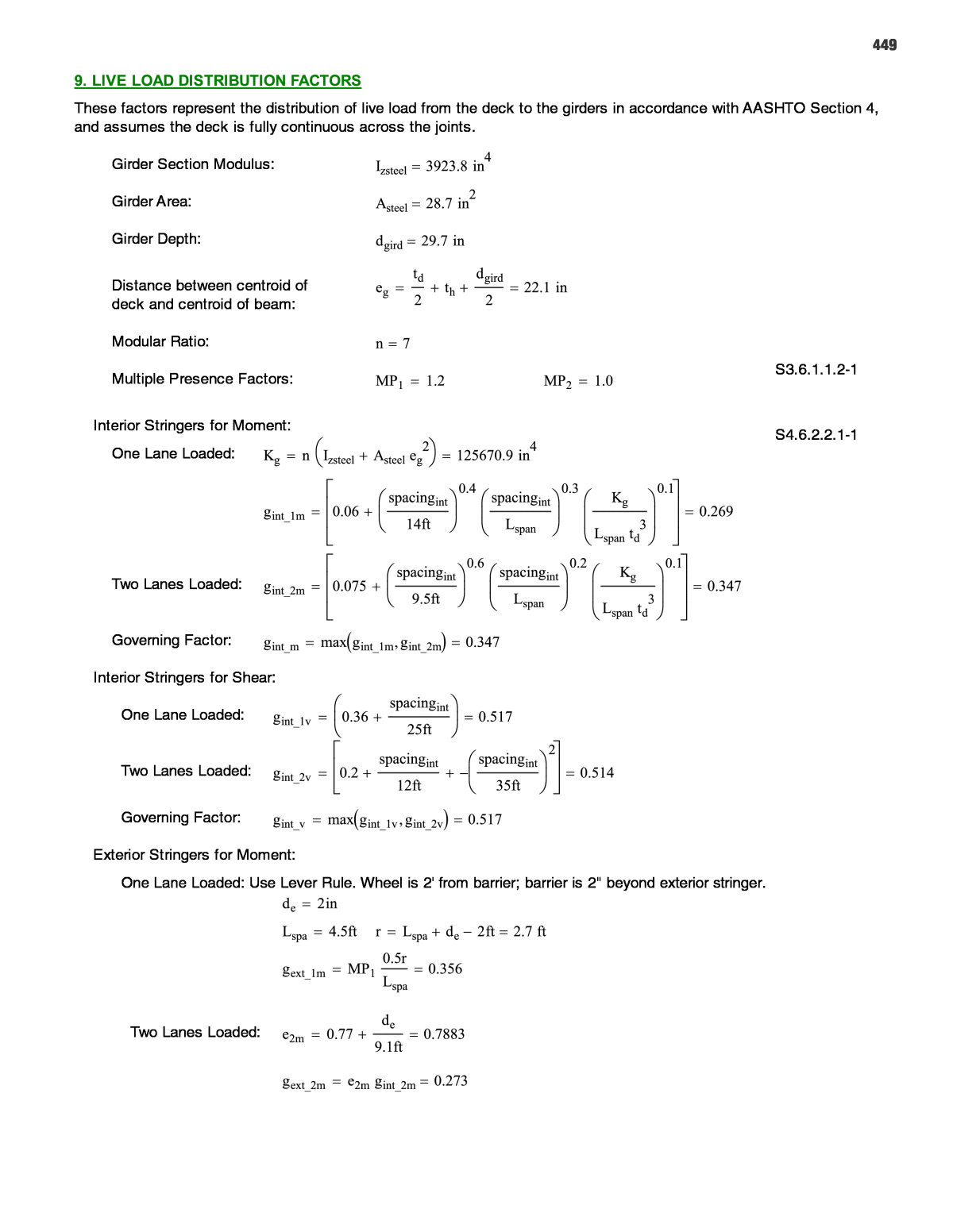
449 These factors represent the distribution of live load from the deck to the girders in accordance with AASHTO Section 4, and assumes the deck is fully continuous across the joints. Girder Section Modulus: Girder Area: Girder Depth: Distance between centroid of deck and centroid of beam: Modular Ratio: S3.6.1.1.2-1 Multiple Presence Factors: Interior Stringers for Moment: S4.6.2.2.1-1 One Lane Loaded: Two Lanes Loaded: Governing Factor: Interior Stringers for Shear: One Lane Loaded: Two Lanes Loaded: Governing Factor: Exterior Stringers for Moment: One Lane Loaded: Use Lever Rule. Wheel is 2' from barrier; barrier is 2" beyond exterior stringer. Two Lanes Loaded:
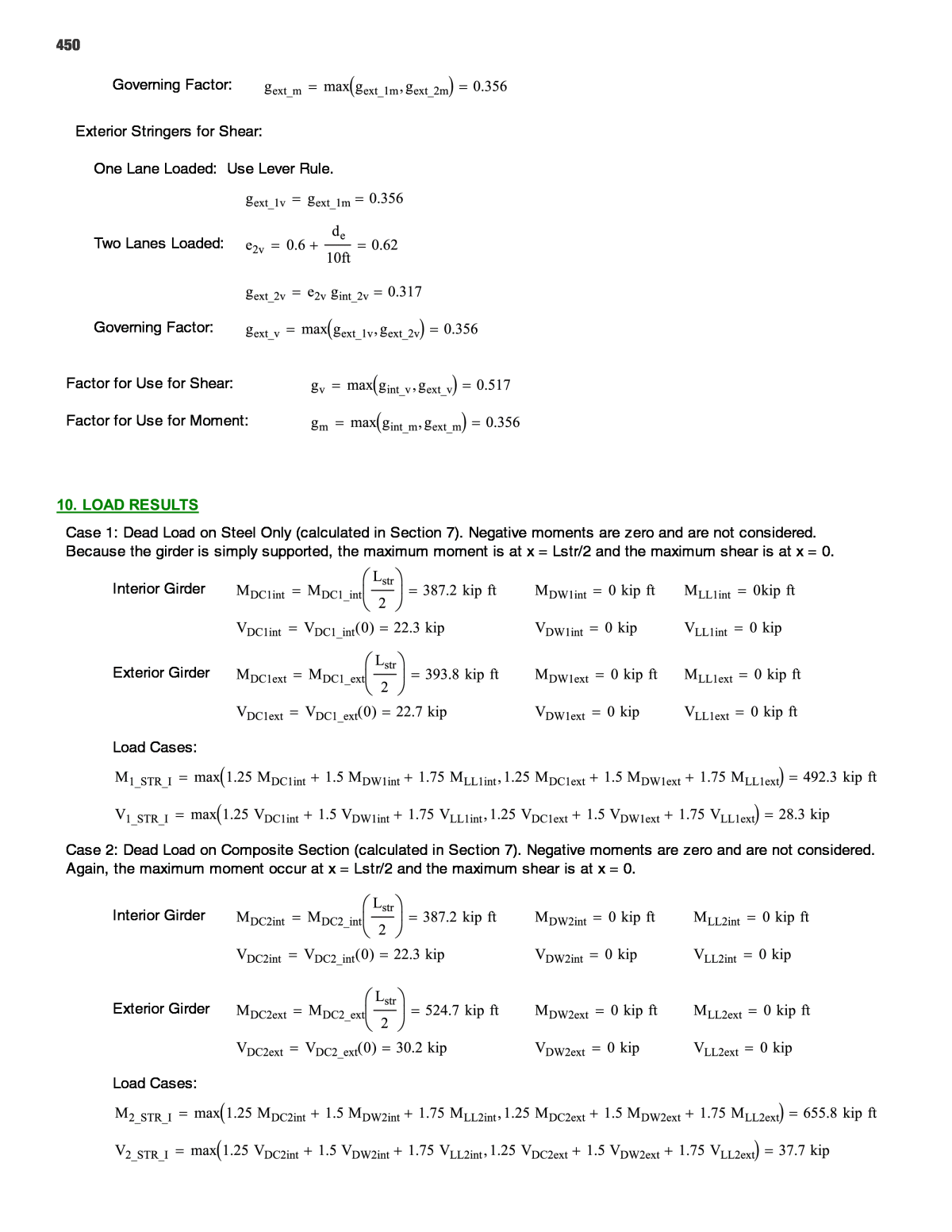
450 Governing Factor: Exterior Stringers for Shear: One Lane Loaded: Use Lever Rule. Two Lanes Loaded: Governing Factor: Factor for Use for Shear: Factor for Use for Moment: Case 1: Dead Load on Steel Only (calculated in Section 7). Negative moments are zero and are not considered. Because the girder is simply supported, the maximum moment is at x = Lstr/2 and the maximum shear is at x = 0. Interior Girder Exterior Girder Load Cases: Case 2: Dead Load on Composite Section (calculated in Section 7). Negative moments are zero and are not considered. Again, the maximum moment occur at x = Lstr/2 and the maximum shear is at x = 0. Interior Girder Exterior Girder Load Cases:
451 Case 3: Composite girders are lifted into place from lifting points located distance Dlift from the girder edges. Maximum moments and shears were calculated in Section 8. Interior Girder Exterior Girder Load Cases: Case 4: Composite girders made continuous. Utilities and future wearing surface are applied, and live load. Maximum moment and shear results are from a finite element analysis not included in this design example. The live load value includes the lane fraction calculated in Section 9, and impact. Governing Loads: Load Cases:
452 The flexural resistance shall be determined as specified in LRFD Design Article 6.10.6.2. Determine Stringer Plastic Moment Capacity First. Find location of PNA: :
453
454 Dp = distance from the top of slab of composite section to the neutral axis at the plastic moment (neglect positive moment reinforcement in the slab).
455 Positive Flexural Compression Check: From LRFD Article 6.10.2 Check for compactness: Web Proportions: Web slenderness Limit: S 6.10.6.2.2 Therefore Section is considered compact and shall satisfy the requirements of Article 6.10.7.1. Negative Moment Capacity Check (Appendix A6): Web Slenderness: S Appendix A6 (for skew less than 20 deg). Moment ignoring concrete: Web Compactness: Check for Permanent Deformations (6.10.4.2): Steel stress on side of Dn Ï Î² β Ï Ï Î² λ λ λ
456 λ Web Plastification: Flexure Factor: Ï Tensile Limit: Ï Compressive Limit: Local Buckling Resistance: λ λ λ λ λ λ λ λ λ Lateral Torsional Buckling Resistance: Inflection point assumed to be at 1/6 span Ï
457 Ï Governing negative moment capacity: Phase 1: First, check the stress due to the dead load on the steel section only. (LRFD 6.10.3 - Constructability Requirements Reduction factor for construction Ï Load Combination for construction Max Moment applied, Phase 1: (at midspan) Maximum Stress, Phase 1: Stress limits: Ï Phase 2: Second, check the stress due to dead load on the composite section (with barriers added) Reduction factor for construction Ï Load Combination for construction Max Moment applied, Phase 2: (at midspan) Capacity for positive flexure: Check Moment: Ï Phase 3: Next, check the flexural stress on the stringer during transport and picking, to ensure no cracking. Reduction factor for construction Ï Load Combination for construction when dynamic construction loads are involved (Section 10). Loads and stresses on stringer during transport and picking: Concrete rupture stress Concrete stress during construction not to exceed: Ï
458 Phase 4: Check flexural capacity under dead load and live load for fully installed continuous composite girders. Strength I Load Combination Ï Ï Strength III Load Combination Ï Strength V Load Combination Ï Check service load combinations for the fully continuous beam with live load (Phase 4): under Service II for stress limits - under Service I for cracking - Ignore positive moment for Service I as there is no tension in the concrete in this case. Service Load Stress Limits: Top Flange: Bottom Flange: Concrete (Negative bending only): Service Load Stresses, Positive Moment: Top Flange: Bottom Flange: Using Service I Loading Service Load Stresses, Negative Moment: Top (Concrete):
459 Bottom Flange: Check LL Deflection: â from independent Analysis - includes 100% design truck (w/impact), or 25% design truck (w/impact) + 100% lane load δ Deflection distribution factor = (no. lanes)/(no. stringers) â δ Equivalent X, where L/X = Deflection*Distribution Factor â δ Shear Capacity based on AASHTO LRFD 6.10.9 Nominal resistance of unstiffened web: Ï Ï Fatigue check shall follow LRFD Article 6.10.5. Moments used for fatigue calculations were found using an outside finite element analysis program. First check Fatigue I (infinite life); then find maximum single lane ADTT for Fatigue II if needed. Fatigue Stress Limits: â Category B: non-coated weathering steel â Category C': Base metal at toe of transverse stiffener fillet welds â Category C: Base metal at shear connectors
460 Fatigue Moment Ranges at Detail Locations (from analysis): γ γ Constants to use for detail checks: Category B Check: Stress at Bottom Flange, Fatigue I γ â γ γ â Category C' Check: Stress at base of transverse stiffener (top of bottom flange) γ â γ γ â Category C Check: Stress at base of shear connectors (top of top flange) γ â
461 γ γ â FATIGUE CHECK: Ensure that single lane ADTT is less than If not, then the beam requires redesign. bp x tp Using LRFD Article 6.10.11 for stiffeners: 9tw x tw 9tw x tw Ï *Check min weld sizeProjecting Width Slenderness Check: bp x tp Stiffener Bearing Resistance: Ï Ï Ï Ï Ï Ï Ï Weld Check: Ï Ï
462 Axial Resistance of Bearing Stiffeners: Ï for bearing stiffeners Ï Ï Shear Connector design to follow LRFD 6.10.10. Stud Properties: Diameter Height of Stud Studs per row Ï Fati Resistance:gue
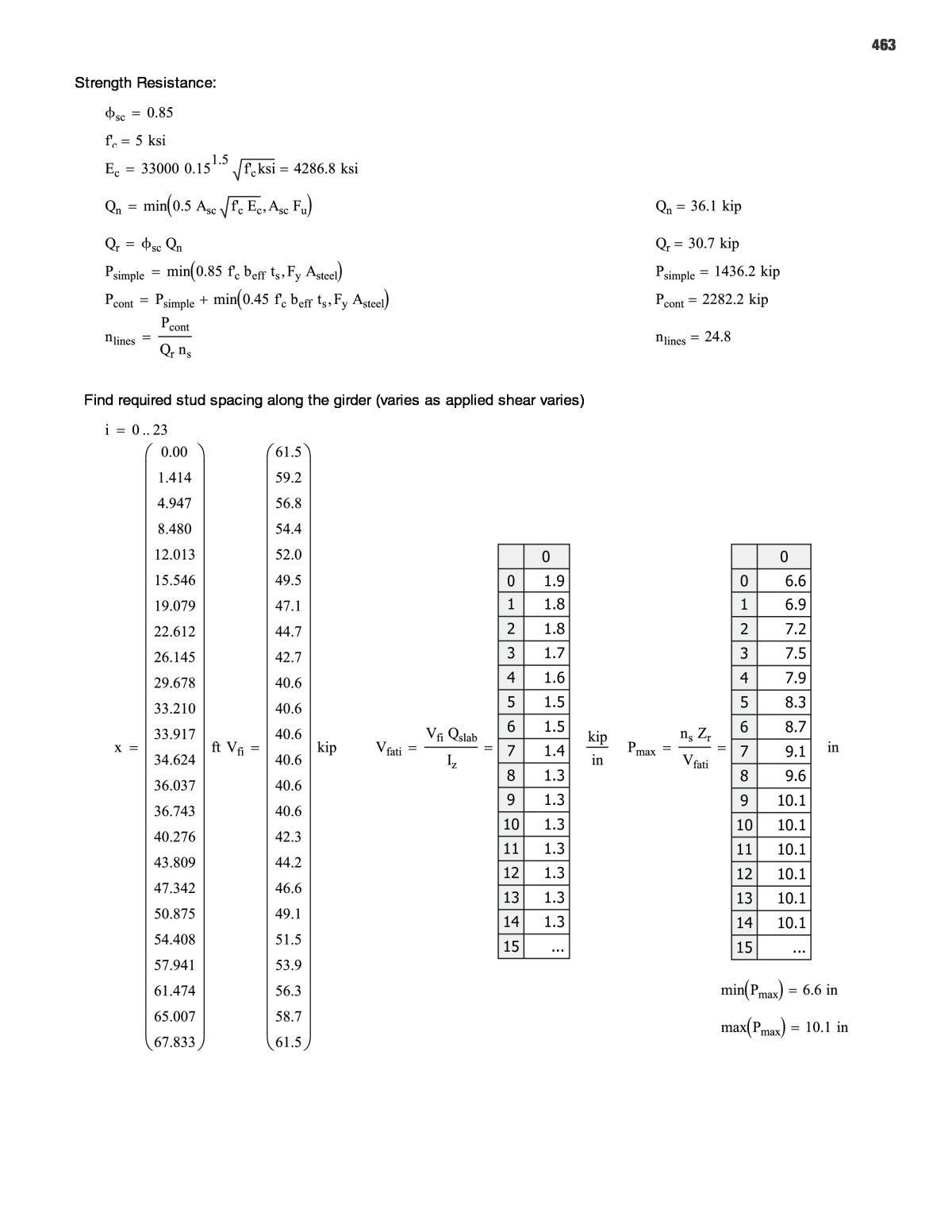
463 Strength Resistance: Ï Ï Find required stud spacing along the girder (varies as applied shear varies) 0 0 1 2 3 4 5 6 7 8 9 10 11 12 13 14 15 1.9 1.8 1.8 1.7 1.6 1.5 1.5 1.4 1.3 1.3 1.3 1.3 1.3 1.3 1.3 ... 0 0 1 2 3 4 5 6 7 8 9 10 11 12 13 14 15 6.6 6.9 7.2 7.5 7.9 8.3 8.7 9.1 9.6 10.1 10.1 10.1 10.1 10.1 10.1 ...
464 This section details the geometric and material properties of the deck. Because the equivalent strip method is used in accordance with AASHTO LRFD Section 4, different loads are used for positive and negative bending. Unit Weight Concrete Deck Thickness for Design Deck Thickness for Loads Rebar yield strength Strength of concrete Concrete clear cover Transverse reinforcement Bottom Reinforcing Ï ÏTop Reinforcing Bottom Spacing Top Spacing Ï Ï Ï Ï Ï Ï Design depth of Bar Ï Ï Girder Spacing Equivalent Strip, +M Equivalent Strip, M Once the strip widths are determined, the dead loads can be calculated.
465 This section calculates the dead loads on the slab. These are used later for analysis to determine the design moments. Weight of deck, +M Weight of deck, M Unit weight of barrier Barrier point load, +M Barrier point load, M This section calculates the live loads on the slab. These loads are analyzed in a separate program with the permanent loads to determine the design moments. Truck wheel load Impact Factor Multiple presence factors Wheel Loads A separate finite element analysis program was used to analyze the deck as an 11-span continuous beam with cantilevered overhangs on either end, with supports stationed at girder locations. The dead and live loads were applied separately. The results are represented here as input values, highlighted. Design Moments Consider a 1'-0" strip: Ï Î² β Bottom: Top: β β β β Ï Ï
466 Longitudinal reinforcement Ï Ï Ï Ï Ï Ï Distribution Reinforcement (AASHTO 9.7.3.2) This section will conduct design checks on the reinforcing according to various sections in AASHTO LRFD. CHECK MINIMUM REINFORCEMENT (AASHTO LRFD 5.7.3.3.2): Modulus of Rupture Section Modulus
467 Unfactored Dead Load S 5.7.3.3.2Cracking Moment Minimum Factored Flexural Resistance CHECK CRACK CONTROL (AASHTO LRFD 5.7.3.4): γ γ Ï Ï Î² β γ β γ β
468 SHRINKAGE AND TEMPERATURE REINFORCING (AASHTO LRFD 5.10.8): SHEAR RESISTANCE (AASHTO LRFD 5.8.3.3): Ï Î² θ β Shear capacity of reinforcing steel Shear capacity of prestressing steel Ï Total factored resistance Total factored load DEVELOPMENT AND SPLICE LENGTHS (AASHTO LRFD 5.11): Development and splice length design follows standard calculations in AASHTO LRFD 5.11, or as dictated by the State DOT Design Manual.
469 Deck Properties: Deck Overhang Length Parapet Properties: Note: Parapet properties are per unit length. Compression reinforcement is ignored. Cross Sectional Area Height of Parapet Parapet Weight Width at base Average width of wall Height of top portion of parapet Width at top of parapet Height of middle portion of parapet Height of lower portion of parapet Width at middle transition of parapet Width at base of parapet Parapet Center of Gravity Parapet Reinforcement Vertically Aligned Bars in Wall Horizontal Bars Rebar spacing: Rebar Diameter: Ï Ï Rebar Area: Ï Ï Ï Ï Cover: Ï Effective Depth: Ï Ï Parapet Moment Resistance About Horizontal Axis: Ï S 5.7.3.1.2-4 S 5.7.3.2.3Depth of EquivalentStress Block: Moment Capacity of Upper Segment of Barrier (about longitudinal axis): Average width of section Cover Ï Depth Factored Moment Resistance Ï Ï Moment Capacity of Middle Segment of Barrier (about longitudinal axis):
470 Average width of section Cover Ï Depth Factored Moment Resistance Ï Ï Parapet Base Moment Resistance (about longitudinal axis): Ï Development in tension Ï Ï Ï Ï Ï Ï Ï Hooked bar developed in tension Ï Ï Lap splice in tension Distance from NA to Compressive Face β S 5.7.3.1.2-4
471 Depth of Equivalent Stress Block β S 5.7.3.2.3 Nominal Moment Resistance S 5.7.3.2.2-1 Factored Moment Resistance Ï S 5.7.3.2 Average Moment Capacity of Barrier (about longitudinal axis): Factored Moment Resistance about Horizontal Axis Ï Ï Parapet Moment Resistance (about vertical axis): Height of Transverse Reinforcement in Parapet Width of Parapet at Transverse Reinforcement Depth of Equivalent Stress Block Concrete Cover in Parapet Ï Ï Ï Ï Ï Ï Design depth Nominal Moment Resistance - Tension on Inside Face Ï Ï Ï Ï Ï Ï Ï Ï Ï Ï
472 Ï Ï Ï Ï Ï Nominal Moment Resistance - Tension on Outside Face Ï Ï Ï Ï Ï Ï Ï Ï Ï Ï Ï Ï Ï Ï Ï Vertical Nominal Moment Resistance of Parapet Parapet Design Factors: Crash Level Transverse Design Force Longitudinal Design Force Vertical Design Force (Down) Critical Length of Yield Line Failure Pattern:
473 S A13.3.1-2 S A13.3.1-1 S A13.4.2-1 The parapet design must consider three design cases. Design Case 1 is for longitudinal and transverse collision loads under Extreme Event Load Combination II. Design Case 2 represents vertical collision loads under Extreme Event Load Combination II; however, this case does not govern for decks with concrete parapets or barriers. Design Case 3 is for dead and live load under Strength Load Combination I; however, the parapet will not carry wheel loads and therefore this case does not govern. Design Case 1 is the only case that requires a check. DC - 1A: Inside face of parapet S A13.4.1 S Table 3.4.1-1Ï Î³ γ γ γ γ Ï Ï Ï Ï Ï Ï Î² β Ï Ï Ï Ï Ï
474 DC - 1B: Design Section in Overhang Notes: Distribution length is assumed to increase based on a 30 degree angle from the face of parapet. Moment of collision loads is distributed over the length Lc + 30 degree spread from face of parapet to location of overhang design section. Axial force of collision loads is distributed over the length Lc + 2Hpar + 30 degree spread from face of parapet to location of overhang design section. Future wearing surface is neglected as contribution is negligible. γ γ Ï Ï Ï DC - 1C: Design Section in First Span Assumptions: Moment of collision loads is distributed over the length Lc + 30 degree spread from face of parapet to location of overhang design section. Axial force of collision loads is distributed over the length Lc + 2Hpar + 30 degree spread from face of parapet to location of overhang design section. Future wearing surface is neglected as contribution is negligible. (From model output)
475 Ï Ï Ï Maximum crash load moment at theoretical cut- ff point: Ï Ï Ï Ï Ï Ï
476 Ï Ï Ï Ï extension past second interior girder Does not govern - no live load on overhang. See sheet S7 from drawing set titled: "STANDARD CONCEPTS FOR ABC MODULAR SYSTEMS" Ensure compression splice and connection can handle the compressive force in the force couple due to the negative moment over the pier. Live load negative moment over pier: Factored LL moment: The compression splice is comprised of a splice plate on the underside of the bottom flange, and built-up angles on either side of the web, connecting to the bottom flange as well. Calculate Bottom Flange Stress: Composite moment of inertia: Distance to center of bottom flange from composite section centroid: Stress in bottom flange: Calculate Bottom Flange Force: Design Stress: Effective Flange Area:
477 Force in Flange: Calculate Bottom Flange Stress, Ignoring Concrete: Moment of inertia: Distance to center of bottom flange: Stress in bottom flange: Bottom Flange Force for design: Design Stress: Design Force: Compression Splice Plate Dimensions: Bottom Splice Plate: Built-Up Angle Splice Plate Horizontal Leg: Built-Up Angle Splice Plate Vertical Leg: Total Area: Average Stress: Proportion Load into each plate based on area: Check Plates Compression Capacity: Bottom Splice Plate: for bolted connection Ï
478 Horizontal Angle Leg: for bolted connection Ï
479 Vertical Angle Leg: for bolted connection Ï Additional Checks: Design Bolted Connections of the splice plates to the girders, checking for shear, bearing, and slip critical connections. See sheet S2 from drawing set titled: "STANDARD CONCEPTS FOR ABC MODULAR SYSTEMS" for closure pour drawing. Check the closure pour according to the negative bending capacity of the section. Use the minimum reinforcing properties for design, to be conservative.
480 Overall CG: Moment of Inertia: Section Moduli: Concrete Properties: Steel Properties: Negative Flexural Capacity: Slenderness ratio for compressive flange: λ Limiting ratio for compactness: λ Limiting ratio for noncompact λ Hybrid Factor: Flange compression resistance: λ λ λ λ λ λ
481 Lateral Torsional Buckling Resistance: Ï Compressive Resistance: Tensile Flexural Resistance: For Strength For Service Ultimate Moment Resistance: from external FE analysis For additional design, one may calculate the force couple at the section over the pier to find the force in the UHPC closure joint. This force can be used to design any additional reinforcement used in the joint.
482 ABC SAMPLE CALCULATION â 2 Decked Precast Prestressed Concrete girder Design for ABC
483 DECKED PRECAST PRESTRESSED CONCRETE GIRDER DESIGN FOR ABC Unit Definition: kcf kip ft 3 This example is for the design of a superstructure system that can be used for rapid bridge replacement in an Accelerated Bridge Construction (ABC) application. The following calculations are intended to provide the designer guidance in developing a similar design with regard to design consideration characteristic of this type of construction, and they shall not be considered fully exhaustive. Overall Width, W Roadway Width, WrBarrier Width, Wb Joint Width, Wj Slope, CS Beam Spacing, SS Wj 2 TYPICAL SECTION THROUGH SPAN Lend Design Span Length, L Girder Length, Lg GIRDER ELEVATION BRIDGE GEOMETRY L 70 ft Lend 2 ft skew 0 deg W 47.167 ft Wb 1.5 ft Smax 8 ft Wj 0.5 ft Ng ceil W Wj Smax 6 Minimum number of girders in cross-section S W Wj Ng 7.945 ft Girder spacing
484 ORDER OF CALCULATIONS Introduction1. Design Philosophy2. Design Criteria3. Beam Section4. Material Properties5. Permanent Loads6. Precast Lifting Weight7. Live Load8. Prestress Properties9. Prestress Losses10. Concrete Stresses11. Flexural Strength12. Shear Strength13. Splitting Resistance14. Camber and Deflections15. Negative Moment Flexural Strength16. 1. INTRODUCTION The superstructure system considered here consists of precast prestressed concrete girders with a top flange width nominally equal to the beam spacing, such that the top flange will serve as the riding surface once closure joints between the girders are poured. The intended use of these girders is to facilitate rapid bridge construction by providing a precast deck on the girder, thereby eliminating the need for a cast-in-place deck in the field. Concepts used in this example are taken from previous and on-going research, the focus of which is overcoming issues detracting from the benefits of decked precast beams and promoting widespread acceptance by transportation agencies and the construction industry. The cross-section is adapted from the optimized girder sections recommended by NCHRP Project No. 12-69, Design and Construction Guidelines for Long-Span Decked Precast, Prestressed Concrete Girder Bridges. The section considered here has an additional 3" added to the top flange to accommodate the joint continuity detail utilized in this project. The girder design does not include the option to re-deck because the final re-decked system, without additional prestressing, is generally expected to have a shorter span length capability, effectively under-utilizing the initial precast section. Sacrificial wearing thickness, use of stainless steel rebars and the application of a future membrane and wearing surface can mitigate the need to replace the deck, so these characteristics are included in lieu of "re-deckability " The bridge used in this example represents a typical design problem. The calculations are equally as applicable to a single- span or multiple-span bridge because beam design moments are not reduced for continuity in multiple-span bridges at intermediate support. Design of the continuity details is not addressed in this example. The cross-section consists of a two- lane roadway with normal crown, bordered by standard barrier wall along each fascia. The structural system is made up of uniformly spaced decked precast prestressed concrete girders set normal to the cross-slope to allow for a uniform top flange and to simplify bearing details. The girder flanges are 9" at the tips, emulating an 8" slab with an allowance (1/2") for wear and an additional allowance (1/2") for grinding for smoothness and profile adjustment. The intent of this example is t illustrate aspects of design unique to decked precast prestressed girders used in an ABC application. Prestress forces and concrete stresses at the service limit states due to the uncommon cross-section, unusually high self-weight, and unconventional sequence of load application are of particular concern, and appropriate detailed calculations are included. Flexure and shear at the strength limit state are not anticipated to differ significantly from a conventional prestressed beam design. With the exception of computing flexural resistance at midspan, flexure and shear are omitted from this example for brevity. Omission of these checks does not indicate they are not necessary, nor does it relieve the designer of the responsibility to satisfy any and all design requirements, as specified by AASHTO and the Owner.
485 2. DESIGN PHILOSOPHY Geometry of the section is selected based on availability of standard formwork across many geographic regions, as evidenced by sections commonly used by many state transportation agencies. Depth variations are limited to constant- thickness region of the web, maintaining the shapes of the top flange and bottom bulb. Concrete strengths can vary widely, and strengths ranging from below 6 ksi to over 10 ksi are common. For the purposes of these calculations, concrete with a 28-day minimum compressive strength of 8 ksi is used. Because this beam is unable to take advantage of the benefits of composite behavior due to its casting sequence, and because allowable tension in the bottom of the beam at the service limit state is limited (discussed in Section 4), end region stresses are expected to be critical. Therefore, minimum concrete strength at release is required to be 80 percent of the 28-day compressive strength of the concrete, increasing the allowable stresses at the top and bottom of the section. The prestressing steel can also be optimized to minimize the stresses in the end region, as discussed below. Prestressing steel is arranged in a draped, or harped, pattern in order to maximize its effectiveness at midspan while minimizing its eccentricity at the ends of the beam where the concrete is easily overstressed because there is little positive dead load moment to offset the negative prestress moment. Effectiveness of the strand group is optimized at midspan by bundling the harped strands between hold-down points, maximizing the eccentricity of the strand group. The number and deflection angle of the harped strands is constrained by an upper limit on the hold-down force required for a single strand and for a single hold-down device, i.e., the entire group of strands. For longer spans, concrete stresses in the end regions at release will be excessive, and debonding without harped strands is not likely to reduce stresses to within allowable limits. Therefore, since harped strands will be required, this method of stress relief will be used exclusively without debonding. Temporary strands are not considered. 3. DESIGN CRITERIA In addition to the provisions of AASHTO, several criteria have been selected to govern the design of these beams, based on past and current practice, as well as research related to decked precast sections and accelerated bridge construction. The following is a summary of limiting design values for which the beams are proportioned, and they are categorized as section constraints, prestress limits, and concrete limits: Section Constraints: Wpc.max 200 kip Upper limit on the weight of the entire precast element, based on common lifting and transport capabilities without significantly increasing time and/or cost due to unconventional equipment or permits Smax 8 ft Upper limit on girder spacing and, therefore, girder flange width (defined on first page) Prestress Limits: Fhd.single 4 kip Maximum hold-down force for a single strand Fhd.group 48 kip Maximum hold-down force for the group of harped strands Stress limits in the prestressing steel immediately prior to prestress and at the service limit state after all losses are as prescribed by AASHTO LRFD.
486 Concrete Limits: Allowable concrete stresses are generally in line with AASHTO LRFD requirements, with one exception. Allowable tension in the bottom of the section at final, Service III, is limited to 0 ksi, based on the research of NCHRP Project No. 12-69. Imposing this limitation precludes the need to evaluate the flexural effects on the girder section arising from forces applied to correct differential camber between adjacent beams. The reliability of this approach is enhanced without the need for additional calculations by specifying a differential camber tolerance equally as, or more stringent than, the tolerance assumed in the subject project. For the purposes of this example, the differential camber tolerance is assumed be at least as stringent. ft.all.ser 0 ksi Allowable bottom fiber tension at the Service III Limit State, when camber leveling forces are to be neglected, regardless of exposure As previously mentioned, release concrete strength is specified as 80 percent of the minimum 28-day compressive strength to maximize allowable stresses in the end region of beam at release. fc.rel f( ) 0.80 f Minimum strength of concrete at release At the intermediate erection stage, stresses in the beam due to various lifting and transportation support conditions need to be considered. Using AASHTO LRFD Table 5.9.4.2.1-1, allowable compression during handling can be limited to 60% of the concrete strength. This provision is not explicitly applicable to this case, however, it does apply to handling stresses in prestressed piling and is more appropriate than the more restrictive sustained permanent load limit of 45% due to anticipated dynamic dead load effects. For allowable tension, a "no cracking" approach is considered due to reduced lateral stability after cracking. Therefore, allowable tension is limited to the modulus of rupture, further modified by an appropriate factor of safety. Both allowable values are based on the concrete strength at the time of lifting and transportation. At this stage, assuming the beams will be lifted sometime after release and before the final strength is attained, allowable stresses are based on the average of the release strength and the specified 28-day strength, i.e., 90% of the specified strength. DIM 30% Dynamic dead load allowance fc.erec f( ) 0.90 f Assumed attained concrete strength during lifting and transportation FSc 1.5 Factor of safety against cracking during lifting transportation ft.erec f( ) 0.24 f ksi FSc Allowable tension in concrete during lifting and transportation to avoid cracking
487 b1 b2 b3 bn+1 bn bn-1 bn-2 dn dn-1 dn-2 d1 d2 TYPICALGIRDER SECTION COMPRISED OF n TRAPEZOIDAL REGIONS y x 4. BEAM SECTION Use trapezoidal areas to define the cross-section. The flange width is defined as the beam spacing less the width of the longitudinal closure joint to reflect pre-erection conditions. Live load can be conservatively applied to this section, as well. h 42 in Beam section depth tflange 9 in Flange thickness at tip tsac 1 in Total sacrificial depth for grinding and wear b1 26 in b2 26 in d1 7 in b2 26 in b3 6 in d2 3 in b3 6 in b4 6 in b4 6 in b5 10 in d4 2 in b5 10 in b6 49 in d5 3 in b6 49 in b7 S Wj d6 0 in b7 89.334 in b8 S Wj d7 tflange tsac d3 h tsac d d3 18 in bf 89.334 in Precast girder flange width Ag 1157.172 in 2 Cross-sectional area (does not include sacrifical thickness) Ixg 203462 in 4 Moment of inertia (does not include sacrificial thickness) ytg 12.649 in ybg 28.351 in Top and bottom fiber distances from neutal axis (positive up) Stg 16085.5 in 3 Sbg 7176.5 in 3 Top and bottom section moduli Iyg 493395 in 4 Weak-axis moment of inertia 50 40 30 20 10 0 10 20 30 40 50 2 3.75 9.5 15.25 21 26.75 32.5 38.25 44 GIRDER SECTION PLOT (N.T.S.)
488 5. MATERIAL PROPERTIES Concrete: f'c 8 ksi Minimum 28-day compressive strength of concrete fci fc.rel f'c 6.4 ksi Minimum strength of concrete at release γc .150 kcf Unit weight of concrete K1 1.0 Correction factor for standard aggregate (5.4.2.4) Eci 33000 K1 γc kcf 1.5 fci ksi 4850 ksi Modulus of elasticity at release (5.4.2.4-1) Ec 33000 K1 γc kcf 1.5 f'c ksi 5422 ksi Modulus of elasticity (5.4.2.4-1) fr.cm 0.37 f'c ksi 1.047 ksi Modulus of rupture for cracking moment (5.4.2.6) fr.cd 0.24 f'c ksi 0.679 ksi Modulus of rupture for camber and deflection (5.4.2.6) H 70 Relative humidity (5.4.2.3) Prestressing Steel: fpu 270 ksi Ultimate tensile strength fpy 0.9 fpu 243 ksi Yield strength, low-relaxation strand (Table 5.4.4.1-1) fpbt.max 0.75 fpu 202.5 ksi Maximum stress in steel immediately prior to transfer fpe.max 0.80 fpy 194.4 ksi Maximum stress in steel after all losses Ep 28500 ksi Modulus of elasticity (5.4.4.2) dps 0.5 in Strand diameter Ap 0.153 in 2 Strand area Nps.max 40 Maximum number of strands in section npi Ep Eci 5.9 Modular ratio at release np Ep Ec 5.3 Modular ratio Mild Steel: fy 60 ksi Specified minimum yield strength Es 29000 ksi Modulus of elasticity (5.4.3.2)
489 6. PERMANENT LOADS Permanent loads to be considered in the design of this girder are self-weight, diaphragms, barrier, and future wearing surface. The barrier can be cast with the beam, superimposed on the exterior girder only in the field, or superimposed on the bridge after the closure joints have attained sufficient strength. Distribution of the barrier weight to the girders should accurately reflect the stage at which it was installed. In this example, the barrier is assumed to be cast on the exterior girder in the casting yard, after release of prestress, but prior to shipping. This concept increases the dead load to be supported by the exterior girder while eliminating a time-consuming task to be completed in the field. BeamLoc 1 Location of beam within the cross-section (0 - Interior, 1 - Exterior) Load at Release: γc.DL .155 kcf Concrete density used for weight calculations Ag.DL Ag tsac S Wj 1246.506 in 2 Area used for weight calculations, including sacrificial thickness wg Ag.DL γc.DL 1.342 klf Uniform load due to self-weight, including sacrificial thickness Lg L 2 Lend 74 ft Span length at release Mgr x( ) wg x 2 Lg x Moment due to beam self-weight (supported at ends) Vgr x( ) wg Lg 2 x Shear due to beam self-weight (supported at ends) Load at Erection: Mg x( ) wg x 2 L x( ) Moment due to beam self-weight Vg x( ) wg L 2 x Shear due to beam self-weight wbar 0.430 klf Uniform load due to barrier weight, exterior beams only wbar if BeamLoc 1= wbar 0 0.43 klf Redefine to 0 if interior beam (BeamLoc = 0) Mbar x( ) wbar x 2 L x( ) Moment due to beam self-weight Vbar x( ) wbar L 2 x Shear due to beam self-weight
490 Load at Service: pfws 25 psf Assumed weight of future wearing surface wfws pfws S 0.199 klf Uniform load due to future wearing surface Mfws x( ) wfws x 2 L x( ) Moment due to future wearing surface Vfws x( ) wfws L 2 x Shear due to future wearing surface wj Wj d7 γc.DL 0.052 klf Uniform load due to weight of longitudinal closure joint Mj x( ) wj x 2 L x( ) Moment due to longitudinal closure joint Vj x( ) wj L 2 x Shear due to longitudinal closure joint 7. PRECAST LIFTING WEIGHT Precast Superstructure Wg wg wbar Lg 131.1 kip Precast girder, including barrier if necessary Substructure Precast with Superstructure Lcorb 1 ft Length of approach slab corbel Bcorb bf bf 89.334 in Width of corbel cast with girder Dcorb 1.5 ft Average depth of corbel Vcorb Lcorb Bcorb Dcorb 11.17 ft 3 Volume of corbel Lia 2.167 ft Length of integral abutment Lgia 1.167 ft Length of girder embedded in integral abutment Bia S Wj 7.444 ft Width of integral abutment cast with girder Dia h 4 in 46 in Depth of integral abutment Via Vcorb Lia Bia Dia Ag tflange bf Lgia 70.14 ft 3 Volume of integral abutment cast with girder Wia Via γc 11 kip Weight of integral abutment cast with girder
491 Lsa 2.167 ft Length of semi-integral abutment Lgsa 4 in Length of girder embedded in semi-integral abutment Bsa S Wj 7.444 ft Width of semi-integral abutment cast with girder Dsa h 16 in 58 in Depth of semi-integral abutment Vsa Vcorb Lsa Bsa Dsa Ag tflange bf Lgsa 88.32 ft 3 Volume of semi-integral abutment cast with girder Wsa Vsa γc 13 kip Weight of semi-integral abutment cast with girder Semi-Integral Abutment Backwall Integral Abutment Backwall
492 8. LIVE LOAD Vehicular loading conforms to the HL-93 design load prescribed by AASHTO. If project-specific erection schemes require the bridge to support construction loads at any stage of erection, these loads should be considered as a separate load case and applied to the beam section at an appropriate attained age of the concrete. Longitudinal joint is designed and detailed for a full moment connection. Therefore, the beams are considered "sufficiently connected to act as a unit" and distribution factors are computed for cross-section type "j", as defined in AASHTO 4.6.2.2. For purposes of computing the longitudinal stiffness parameter, the constant-depth region of the top flange is treated as the slab and the remaining area of the beam section is considered the non-composite beam. Distribution Factors for Moment: From Table 4.6.2.2.2b-1 for moment in interior girders, Ibb 59851 in 4 Moment of inertia of section below the top flange Abb 442.5 in 2 Area of beam section below the top flange eg h tsac ts 2 ybb 22.617 in Distance between c.g.'s of beam and flange Kg 1.0 Ibb Abb eg 2 286209 in4 Longitudinal stiffness parameter (Eqn. 4.6.2.2.1-1) Verify this girder design is within the range of applicability for Table 4.6.2.2.2b-1. CheckMint if S 16 ft( ) S 3.5 ft( ) ts 4.5 in ts 12.0 in L 20 ft( ) L 240 ft( ) "OK" "No Good" CheckMint if CheckMint "OK"=( ) Ng 4 Kg 10000 in4 Kg 7000000 in4 "OK" "No Good" CheckMint "OK" gmint1 0.06 S 14 ft 0.4 S L 0.3 Kg L ts 3 0.1 0.458 Single loaded lane gmint2 0.075 S 9.5 ft 0.6 S L 0.2 Kg L ts 3 0.1 0.633 Two or more loaded lanes gmint max gmint1 gmint2 0.633 Distribution factor for moment at interior beams From Table 4.6.2.2.2d-1 for moment in exterior girders, de S 2 Wb 29.667 in CheckMext if de 1 ft de 5.5 ft Ng 4 "OK" "No Good" "OK"
493 For a single loaded lane, use the Lever Rule. gmext1 S 0.5 bf Wb 5 ft S 0.65 Single loaded lane em 0.77 de 9.1 ft 1.042 gmext2 em gmint 0.659 Two or more loaded lanes gmext max gmext1 gmext2 0.659 Distribution factor for moment at exterior beams Distribution Factors for Shear: From Table 4.6.2.2.3a-1 for shear in interior girders, Verify this girder design is within the range of applicability for Table 4.6.2.2.3a-1. CheckVint if S 16 ft( ) S 3.5 ft( ) ts 4.5 in ts 12.0 in L 20 ft( ) L 240 ft( ) "OK" "No Good" CheckVint if CheckMint "OK"=( ) Ng 4 "OK" "No Good" CheckVint "OK" gvint1 0.36 S 25 ft 0.678 Single loaded lane gvint2 0.2 S 12 ft S 35 ft 2.0 0.811 Two or more loaded lanes gvint max gvint1 gvint2 0.811 Distribution factor for shear at interior beams From Table 4.6.2.2.3b-1 for shear in exterior girders, For a single loaded lane, use the Lever Rule. CheckVext if de 1 ft de 5.5 ft Ng 4 "OK" "No Good" "OK" g1 S 0.5 bf Wb 5 ft S 0.65 Single loaded lane (same as for moment) ev 0.6 de 10 ft 0.847 g2 ev gvint 0.687 Two or more loaded lanes gvext max g1 g2 0.687 Distribution factor for shear at exterior beams
494 From Table 4.6.2.2.3c-1 for skewed bridges, θ skew 0 deg CheckSkew if θ 60 deg( ) 3.5 ft S 16 ft( ) 20 ft L 240 ft( ) Ng 4 "OK" "No Good" "OK" cskew 1.0 0.20 L ts 3 Kg 0.3 tan θ( ) 1.00 Correction factor for skew Design Live Load Moment at Midspan: wlane 0.64 klf Design lane load Ptruck 32 kip Design truck axle load IM 33% Dynamic load allowance (truck only) Mlane x( ) wlane x 2 L x( ) Design lane load moment Influence coefficient for truck moment calculation δ x( ) x L x 2 L Mtruck x( ) Ptruck δ x( ) max 9 x L x( ) 14 ft 3 x L( ) 4 x L x( ) 9 L x( ) 84 ft 4 L x( ) Design truck moment MHL93 x( ) Mlane x( ) 1 IM( ) Mtruck x( ) HL93 design live load moment per lane Mll.i x( ) MHL93 x( ) gmint Design live load moment at interior beam Mll.e x( ) MHL93 x( ) gmext Design live load moment at exterior beam Mll x( ) if BeamLoc 1= Mll.e x( ) Mll.i x( ) Design live load moment Design Live Load Shear: Vlane x( ) wlane L 2 x Design lane load shear Vtruck x( ) Ptruck 9 L 9 x 84 ft 4 L Design truck shear VHL93 x( ) Vlane x( ) 1 IM( ) Vtruck x( ) HL93 design live load shear Vll.i x( ) VHL93 x( ) gvint Design live load shear at interior beam Vll.e x( ) VHL93 x( ) gvext Design live load shear at exterior beam Vll x( ) if BeamLoc 1= Vll.e x( ) Vll.i x( ) Design live load shear
495 9. PRESTRESS PROPERTIES Because allowable tension at the service limit state is reduced to account for camber leveling forces, the prestress force required at midspan is expected to be excessive in the ends at release without measures to reduce the prestress moment. Estimate losses and prestress eccentricity at midspan to select a trial prestress force that results in a bottom fiber tension stress less than allowable. Compute instantaneous losses in the prestressing steel and check release stresses at the end of the beam. Once end stresses are satisfied, estimate total loss of prestress. As long as computed losses do not differ significantly from the assumed values, the prestress layout should be adequate. Concrete stresses at all limit states are evaluated in Section 9. yp.est 5 in Assumed distance from bottom of beam to centroid of prestress at midspan ycgp.est ybg yp.est 23.35 in Eccentricity of prestress from neutral axis, based on assumed location â fp.est 25% Estimate of total prestress losses at the service limit state Compute bottom fiber service stresses at midspan using gross section properties. X L 2 Distance from support Mdl.ser Mg X( ) Mfws X( ) Mj X( ) Mbar X( ) 1238 kip ft Total dead load moment fb.serIII Mdl.ser 0.8 Mll X( ) Sbg 3.567 ksi Total bottom fiber service stress fpj fpbt.max 202.5 ksi Prestress jacking force fpe.est fpj 1 â fp.est 151.9 ksi Estimate of effective prestress force Aps.est Ag fb.serIII ft.all.ser fpe.est 1 Ag ycgp.est Sbg 5.703 in2 Estimated minimum area of prestressing steel Nps.est ceil Aps.est Ap 38 Estimated number of strands required Nps 38 Number of strands used ( Nps.max 40 ) This number is used to lay out the strand pattern and compute an actual location and eccentricity of the strand group, after which the required area is computed again. If the location estimate was accurate, the recomputed number of strands should not differ from the number defined here. If the estimate was low, consider increasing the number of strands. It should be noted that the number of strands determined in this section is based on assumed prestressed losses and gross section properties and may not accurately reflect the final number of strands required to satisfy design requirements. Concrete stresses are evaluated in Section 10. Strand pattern geometry calculations assume a vertical spacing of 2" between straight strands, as well as harped strands at the ends of the beam. Harped strands are bundled at midpsan, where the centroid of these strands is 5" from the bottom
496 Nh 2 Nps 12if 4 12 Nps 24if 6 24 Nps 30if 6 Nps 30 Nps 30if Nh 14 Assumes all flange rows are filled prior to filling rows in web above the flange, which maximized efficiency. Use override below to shift strands from flange to web if needed to satisfy end stresses. Additional harped strands in web (strands to be moved from flange to web)Nh.add 16 16 strands or half of total strands maximum harped in webNh min Nh Nh.add 16 2 floor Nps 4 Nh 16 yh 1 in 2 in( ) 1 0.5 Nh 1 2 yh 10 in Centroid of harped strands from bottom, equally spaced yhb 5 in Centroid of harped strands from bottom, bundled Ns Nps Nh Ns 22 Number of straight strands in flange ys 1 in 2 in Ns 10if 4 in( ) Ns 20 in Ns 10 Ns 20if 6 in( ) Ns 60 in Ns 20 Ns 24if 3.5 in otherwise ys 4.273 in Centroid of straight strands from bottom yp Ns ys Nh yhb Ns Nh 4.579 in Centroid of prestress from bottom at midspan ycgp ybg yp 23.77 in Eccentricity of prestress from neutral axis Aps.req Ag fb.serIII ft.all.ser fpe.est 1 Ag ycgp Sbg 5.623 in2 Estimated minimum area of prestressing steel Nps.req ceil Aps.req Ap 37 Estimated number of strands required CheckNps if Nps Nps.max Nps.req Nps "OK" "No Good" "OK" Aps.h Nh Ap 2.448 in 2 Area of prestress in web (harped) Aps.s Ns Ap 3.366 in 2 Area of prestress in flange (straight) Aps Aps.h Aps.s 5.814 in 2 Total area of prestress
497 Compute transformed section properties based on prestress layout. Initial Transformed Section (release): Final Transformed Section (service): Ati 1185.5 in 2 Atf 1181.9 in 2 Ixti 219101 in 4 Ixtf 217153 in 4 ytti 13.217 in Stti 16577 in 3 yttf 13.146 in Sttf 16518 in 3 ycgpi 23.204 in Scgpi 9442 in 3 ycgpf 23.275 in Scgpf 9330 in 3 ybti 27.783 in Sbti 7886 in 3 ybtf 27.854 in Sbtf 7796 in 3 Determine initial prestress force after instantaneous loss due to elastic shortening. Use transformed properties to compute stress in the concrete at the level of prestress. Pj fpj Aps 1177.3 kip Jacking force in prestress, prior to losses Stress in concrete at the level of prestress after instantaneous lossesfcgpi Pj 1 Ati ycgpi Scgpi Mgr Lg 2 Scgpi 2.719 ksi Prestress loss due to elastic shortening (5.9.5.2.3a-1)â fpES npi fcgpi 15.978 ksi fpi fpj â fpES 186.522 ksi Initial prestress after instantaneous losses Pi fpi Aps 1084.4 kip Initial prestress force Determine deflection of harped strands required to satisfy allowable stresses at the end of the beam at release. fc.all.rel 0.6 fci 3.84 ksi Allowable compression before losses (5.9.4.1.1) ft.all.rel max 0.0948 fci ksi 0.2 ksi 0.200 ksi Allowable tension before losses (Table 5.9.4.1.2-1) Lt 60 dps 2.5 ft Transfer length (AASHTO 5.11.4.1) ycgp.t ft.all.rel Mgr Lt Stti Pi 1 Ati Stti 18.367 in Prestress eccentricity required for tension ycgp.b fc.all.rel Mgr Lt Sbti Pi 1 Ati Sbti 22.6 in Prestress eccentricity required for compression ycgp.req max ycgp.t ycgp.b 18.367 in Required prestress eccentricity at end of beam
498 Minimum distance to harped prestress centroid from bottom of beam at centerline of bearingyh.brg.req ycgp.req ybti Ns Nh ys Ns Nh 16.488 in Minimum distance between uppermost strand and top of beamytop.min 18 in αhd 0.4 Hold-down point, fraction of the design span length Maximum slope of an individual strand to limit hold-down force to 4 kips/strandslopemax if dps 0.6 in= 1 12 1 8 0.125 Set centroid of harped strands as high as possible to minimize release and handling stressesyh.brg h ytop.min 0.5 Nh 1 2 2 in( ) 17 in yh.brg min yh.brg yhb slopemax αhd L 17 in Verify that slope requirement is satisfied at uppermost strand CheckEndPrestress if yh.brg yh.brg.req "OK" "Verify release stresses." "OK" yp.brg Ns ys Nh yh.brg Ns Nh 9.632 in Centroid of prestress from bottom at bearing slopecgp yp.brg yp αhd L 0.015 Slope of prestress centroid within the harping length ypx x( ) yp slopecgp Lend αhd L x x Lend αhd Lif yp otherwise Distance to center of prestress from the bottom of the beam at any position 10. PRESTRESS LOSSES As with any prestressed concrete design, total prestress loss can be considered as the sum of instantaneous (short-term) and time-dependent (long-term) losses. For pretensioned girders, the instantaneous loss consists of elastic shortening of the beam upon release of the prestress force. The time-dependent losses consist of creep and shrinkage of beam concrete, creep and shrinkage of deck concrete, and relaxation of the prestressing steel. These long-term effects in the girder are further subdivided into two stages to represent a significant event in the construction of the bridge: time between transfer of the prestress force and placement of the deck, and the period of time between placement of the deck and final service. For the specific case of a decked beam, computation of long-term losses is somewhat simplified because the cross-section does not change between these two stages and the term related to shrinkage of the deck concrete is eliminated since the deck is cast monolithically with the beam. There will be no gains or losses in the steel associated with deck placement after transfer. AASHTO provides two procedures for estimating time-dependent losses: Approximate Estimate (5.9.5.3)1. Refined Estimate (5.9.5.4)2. The approximate method is intended for systems with composite decks and is based upon assumptions related to timing of load application, the cross-section to which load is applied (non-composite or composite), and ratios of dead load and live load to total load. The conditions under which these beams are to be fabricated, erected, and loaded differ from the conditions assumed in development of the approximate method. Therefore, the refined method is used to estimate time-dependent losses in the prestressing steel. Time-dependent loss equations of 5.9.5.4 include age-adjusted transformed section factors to permit loss computations using gross section properties.
499 Assumed time sequence in the life of the girder for loss calculations: ti 1 Time (days) between casting and release of prestress tb 20 Time (days) to barrier casting (exterior girder only) td 30 Time (days) to erection of precast section, closure joint pour tf 20000 Time (days) to end of service life Terms and equations used in the loss calculations: Prestressing steel factor for low-relaxation strands (C5.9.5.4.2c)KL 45 VS Ag Peri 4.023 in Volume-to-surface ratio of the precast section ks max 1.45 0.13 VS in 1.0 1.00 Factor for volume-to-surface ratio (5.4.2.3.2-2) khc 1.56 0.008 H 1.00 Humidity factor for creep (5.4.2.3.2-3) khs 2.00 0.014 H 1.02 Humidity factor for shrinkage (5.4.2.3.3-2) kf 5 1 fci ksi 0.676 Factor for effect of concrete strength (5.4.2.3.2-4) ktd t( ) t 61 4 fci ksi t Time development factor (5.4.2.3.2-5) Ï t tinit 1.9 ks khc kf ktd t( ) tinit 0.118 Creep coefficient (5.4.2.3.2-1) εsh t( ) ks khs kf ktd t( ) 0.48 10 3 Concrete shrinkage strain (5.4.2.3.3-1) Time from Transfer to Erection: Eccentricity of prestress force with respect to the neutral axis of the gross non-composite beam, positive below the beam neutral axisepg yp ybg 23.772 in Stress in the concrete at the center prestress immediately after transferfcgp Pi 1 Ag epg 2 Ixg Mg L 2 Ixg yp ybg 2.797 ksi fpt max fpi 0.55 fpy 186.522 ksi Stress in strands immediately after transfer (5.9.5.4.2c-1) Ïbid Ï td ti 0.589 Creep coefficient at erection due to loading at transfer Ïbif Ï tf ti 1.282 Creep coefficient at final due to loading at transfer Concrete shrinkage between transfer and erection εbid εsh td ti 1.490 10 4
500 Kid 1 1 npi Aps Ag 1 Ag epg 2 Ixg 1 0.7 Ïbif 0.809 Age-adjusted transformed section coefficient (5.9.5.4.2a-2) â fpSR εbid Ep Kid 3.435 ksi Loss due to beam shrinkage(5.9.5.4.2a-1) â fpCR npi fcgp Ïbid Kid 7.831 ksi Loss due to creep(5.9.5.4.2b-1) â fpR1 fpt KL log 24 td log 24 ti fpt fpy 0.55 1 3 â fpSR â fpCR fpt Kid 1.237 ksi Loss due to relaxation(C5.9.5.4.2c-1 â fpid â fpSR â fpCR â fpR1 12.502 ksi Time from Erection to Final: epc epg 23.772 in Eccentricity of prestress force does not change Ac Ag Ic Ixg Section properties remain unchanged Change in concrete stress at center of prestress due to initial time-dependent losses and superimposed dead load. Deck weight is not included for this design. â fcd Mfws L 2 Mj L 2 Scgpf â fpid np 2.182 ksi Ïbdf Ï tf td 0.858 Creep coefficient at final due to loading at erection εbif εsh tf ti 3.302 10 4 Concrete shrinkage between transfer and final εbdf εbif εbid 1.813 10 4 Concrete shrinkage between erection and final Kdf 1 1 npi Aps Ac 1 Ac epc 2 Ic 1 0.7 Ïbif 0.809 Age-adjusted transformed section coefficient remains unchanged â fpSD εbdf Ep Kdf 4.179 ksi Loss due to beam shrinkage â fpCD npi fcgp Ïbif Ïbid Kdf np â fcd Ïbdf Kdf 17.168 ksi Loss due to creep â fpR2 â fpR1 1.237 ksi Loss due to relaxation â fpSS 0 Loss due to deck shrinkage â fpdf â fpSD â fpCD â fpR2 â fpSS 22.584 ksi
501 Prestress Loss Summary â fpES 15.978 ksi â fpES fpj 7.9 % â fpLT â fpid â fpdf 35.087 ksi â fpLT fpj 17.3 % â fpTotal â fpES â fpLT 51.065 ksi â fpTotal fpj 25.2 % â fp.est 25 % fpe fpj â fpTotal 151.4 ksi Final effective prestress CheckFinalPrestress if fpe fpe.max "OK" "No Good" "OK" 11. CONCRETE STRESSES Stresses in the concrete section at release, during handling, and at final service are computed and checked against allowable values appropriate for the stage being considered. Concrete Stresses at Release Stresses at release are computed using the overall beam length as the span because the beam will be supported at its ends in the casting bed after the prestress force is transfered. Define locations for which stresses are to be calculated: xr Lg 0 min Lt Lg Lend Lg max Lt Lg Lend Lg 0.1 0.2 0.3 αhd 0.5 T ir 1 last xr Functions for computing beam stresses: ftop.r x( ) min x Lt 1 Pi 1 Ati ybti ypx x( ) Stti Mgr x( ) Stti Top fiber stress at release fbot.r x( ) min x Lt 1 Pi 1 Ati ybti ypx x( ) Sbti Mgr x( ) Sbti Bottom fiber stress at release
502 0 4 8 12 16 20 24 28 32 36 40 1 0 1 2 3 4 Stresses in Concrete at Release (Half Beam) Distance along Beam (ft) St re ss (k si) ftop.r x( ) ksi fbot.r x( ) ksi fc.all.rel ksi ft.all.rel ksi 0 x ft Compare beam stresses to allowable stresses. ft.all.rel 0.2 ksi Allowable tension at release fc.all.rel 3.84 ksi Allowable compression at release TopRelir ftop.r xrir TopRelT 0.000 0.148 0.192 0.097 0.002 0.047 0.040 0.062( ) ksi CheckTopRel if max TopRel( ) fc.all.rel min TopRel( ) ft.all.rel "OK" "No Good" "OK" BotRelir fbot.r xrir BotRelT 0.000 2.582 3.241 3.042 2.834 2.738 2.754 2.708( ) ksi CheckBotRel if max BotRel( ) fc.all.rel min BotRel( ) ft.all.rel "OK" "No Good" "OK" Concrete Stresses During Lifting and Transportation Stresses in the beam during lifting and transportation may govern over final service limit state stresses due to different support locations, dynamic effects of dead load during shipment and placement, and lateral bending stresses due to rolling during lifting or superelevation of the roadway during shipping. Assume end diaphragms on both ends of the beam. For prestressing effects, compute the effective prestress force using only the losses occurring between transfer and erection (i.e., the fpid). a h 3.5 ft Maximum distance to lift point from bearing line a' a Lend 5.5 ft Distance to lift point from end of beam
503 Pdia max Wia Wsa 13.2 kip Approximate abutment weight Pm Pj 1 â fpES â fpid fpj 1011.7 kip Effective prestress during lifting and shipping Define locations for which stresses are to be calculated: xe Lg 0 min Lt Lg Lend Lg max Lt Lg Lend Lg a' Lg αhd 0.5 T ie 1 last xe Compute moment in the girder during lifting with supports at the lift points. Mlift x( ) wg wbar x 2 2 Pdia x x a'if Mgr x( ) Mgr a'( ) wg wbar a'( )2 2 Pdia a' otherwise Functions for computing beam stresses: ftop.lift x( ) min x Lt 1 Pm 1 Atf ybtf ypx x( ) Sttf Mlift x( ) Sttf Top fiber stress during lifting Top fiber stress during lifting, impact increasing dead loadftop.DIM.inc x( ) min x Lt 1 Pm 1 Atf ybtf ypx x( ) Sttf Mlift x( ) Sttf 1 DIM( ) Top fiber stress during lifting, impact decreasing dead loadftop.DIM.dec x( ) min x Lt 1 Pm 1 Atf ybtf ypx x( ) Sttf Mlift x( ) Sttf 1 DIM( ) TopLift1ie ftop.lift xeie TopLift1T 0.000 0.230 0.294 0.371 0.181 0.158( ) ksi TopLift2ie ftop.DIM.inc xeie TopLift2T 0.000 0.236 0.302 0.393 0.065 0.035( ) ksi TopLift3ie ftop.DIM.dec xeie TopLift3 T 0.000 0.223 0.285 0.349 0.296 0.282( ) ksi fbot.lift x( ) min x Lt 1 Pm 1 Atf ybtf ypx x( ) Sbtf Mlift x( ) Sbtf Bottom fiber stress during lifting Bottom fiber stress during lifting, impact increasing dead loadfbot.DIM.inc x( ) min x Lt 1 Pm 1 Atf ybtf ypx x( ) Sbtf Mlift x( ) Sbtf 1 DIM( ) Bottom fiber stress during lifting, impact decreasing dead loadfbot.DIM.dec x( ) min x Lt 1 Pm 1 Atf ybtf ypx x( ) Sbtf Mlift x( ) Sbtf 1 DIM( ) BotLift1ie fbot.lift xeie BotLift1T 0.000 2.623 3.292 3.456 3.052 3.005( ) ksi BotLift2ie fbot.DIM.inc xeie BotLift2T 0.000 2.637 3.310 3.502 2.808 2.744( ) ksi
504 BotLift3ie fbot.DIM.dec xeie BotLift3T 0.000 2.609 3.274 3.410 3.297 3.267( ) ksi Allowable stresses during handling: fcm fc.erec f'c 7.2 ksi Assumed concrete strength when handling operations begin fc.all.erec 0.6 fcm 4.32 ksi Allowable compression during lifting and shipping ft.all.erec ft.erec fcm 0.429 ksi Allowable tension during lifting and shipping 0 4 8 12 16 20 24 28 32 36 40 0 2 4 Stresses in Concrete During Lifting (Half Beam) Distance along Beam (ft) St re ss (k si) ftop.lift x( ) ksi ftop.DIM.inc x( ) ksi ftop.DIM.dec x( ) ksi fbot.lift x( ) ksi fbot.DIM.inc x( ) ksi fbot.DIM.dec x( ) ksi fc.all.erec ksi ft.all.erec ksi 0 x ft Compare beam stresses to allowable stresses. TopLiftMaxie max TopLift1ie TopLift2ie TopLift3ie TopLiftMax T 0 0.223 0.285 0.349 0.065 0.035( ) TopLiftMinie min TopLift1ie TopLift2ie TopLift3ie TopLiftMin T 0 0.236 0.302 0.393 0.296 0.282( ) ksi CheckTopLift if max TopLiftMax( ) fc.all.erec min TopLiftMin( ) ft.all.erec "OK" "No Good" "OK" ksi
505 BotLiftMaxie max BotLift1ie BotLift2ie BotLift3ie BotLiftMax T 0 2.637 3.31 3.502 3.297 3.267( ) ksi BotLiftMinie min BotLift1ie BotLift2ie BotLift3ie BotLiftMin T 0 2.609 3.274 3.41 2.808 2.744( ) ksi CheckBotLift if max BotLiftMax( ) fc.all.erec min BotLiftMin( ) ft.all.erec "OK" "No Good" "OK" Concrete Stresses at Final Stresses at final are also computed using the design span length. Top flange compression and bottom flange tension are evaluated at the Service I and Service III limit states, respectively. fc.all.ser1 0.4 f'c 3.2 ksi Allowable compression due to effective prestress and dead load (Table 5.9.4.2.1-1) Allowable compression due to effective prestress, permanent load, and transient loads, as well as stresses during shipping and handling (Table 5.9.4.2.1-1)fc.all.ser2 0.6 f'c 4.8 ksi ft.all.ser 0 ksi Allowable tension (computed previously) Pe fpe Aps 880.4 kip Effective prestress after all losses Compute stresses at midspan and compare to allowable values. ftop.ser1 x( ) min Lend x Lt 1 Pe 1 Atf ybtf ypx x( ) Sttf Mg x Lend Stti Mbar x( ) Mfws x( ) Mj x( ) Sttf ftop.ser2 x( ) min Lend x Lt 1 Pe 1 Atf ybtf ypx x( ) Sttf Mg x Lend Stti Mbar x( ) Mfws x( ) Mj x( ) Mll x( ) Sttf fbot.ser x( ) min Lend x Lt 1 Pe 1 Atf ybtf ypx x( ) Sbtf Mg x Lend Sbti Mbar x( ) Mfws x( ) Mj x( ) 0.8 Mll x( ) Sbtf
506 0 4 8 12 16 20 24 28 32 36 40 0 2 4 6 Stresses in Concrete at Service (Half Beam) Distance along Beam (ft) St re ss (k si) ftop.ser1 x( ) ksi ftop.ser2 x( ) ksi fbot.ser x( ) ksi ft.all.ser ksi fc.all.ser1 ksi fc.all.ser2 ksi x ft Compare beam stresses to allowable stresses. xs L Lt L 0.1 0.15 0.2 0.25 0.3 0.35 αhd 0.45 0.5 T is 1 last xs TopSer1is ftop.ser1 xsis TopSer1 T 0.046 0.101 0.195 0.272 0.330 0.370 0.393 0.397 0.398 0.400( ) ksi TopSer2is ftop.ser2 xsis TopSer2 T 0.075 0.415 0.636 0.820 0.966 1.074 1.148 1.191 1.211 1.212( ) ksi CheckCompSerI if max TopSer1( ) fc.all.ser1 max TopSer2( ) fc.all.ser2 "OK" "No Good" "OK" BotSeris fbot.ser xsis BotSer T 2.218 1.581 1.168 0.825 0.554 0.355 0.221 0.146 0.112 0.109( ) ksi CheckTenSerIII if min BotSer( ) ft.all.ser "OK" "No Good" "OK"
507 12. FLEXURAL STRENGTH Verify flexural resistance at the Strength Limit State. Compute the factored moment at midspan due to the Strength I load combination, then compare it to the factored resistance calculated in accordance with AASHTO LRFD 5.7.3. MDC x( ) Mg x( ) Mbar x( ) Mj x( ) Self weight of components MDW x( ) Mfws x( ) Weight of future wearing surface MLL x( ) Mll x( ) Live load MStrI x( ) 1.25 MDC x( ) 1.5 MDW x( ) 1.75 MLL x( ) Factored design moment For minimum reinforcement check, per 5.7.3.3.2 fcpe Pe 1 Ag ycgp Sbg 3.677 ksi Concrete compression at extreme fiber due to effective prestress Mcr fr.cm fcpe Sbg 2825 kip ft Cracking moment (5.7.3.3.2-1) Mu x( ) max MStrI x( ) min 1.33 MStrI x( ) 1.2 Mcr Design moment Compute factored flexural resistance. β1 max 0.65 0.85 0.05 f'c ksi 4 0.65 Stress block factor (5.7.2.2) k 2 1.04 fpy fpu 0.28 Tendon type factor (5.7.3.1.1-2) Distance from compression fiber to prestress centroiddp x( ) h ypx x Lend dp X( ) 37.421 in hf d7 8 in Structural flange thickness btaper b6 b5 2 19.5 in Average width of taper at bottom of flange htaper d5 3 in Depth of taper at bottom of flange a x( ) Aps fpu 0.85 f'c bf k β1 Aps fpu dp x( ) a X( ) 2.509 in Depth of equivalent stress block for rectangular section c x( ) a x( ) β1 c X( ) 3.861 in Neutral axis location CheckTC if c X( ) dp X( ) .003 .003 .005 "OK" "NG" "OK" Tension-controlled section check (midspan) Resistance factor for prestressed concrete (5.5.4.2)Ï f min 1.0 max 0.75 0.583 0.25 dp X( ) c X( ) 1 1.00
508 fps fpu 1 k c X( ) dp X( ) 262.2 ksi Average stress in the prestressing steel (5.7.3.1.1-1) Ld 1.6 ksi fps 2 3 fpe dps 10.75 ft Bonded strand devlepment length (5.11.4.2-1) fpx x( ) fpe x Lend Lt x Lt Lendif fpe x Lend Lt Ld Lt fps fpe Lt Lend x Ld Lendif fps otherwise Stress in prestressing steel along the length for bonded strand (5.11.4.2) Mr x( ) Ï f Aps fpx x( ) dp x( ) a x( ) 2 Flexure resistance along the length xmom L 0.01 Lt Lend L Ld Lend L αhd 0.5 T imom 1 last xmom Mrximom Mr xmomimom Muximom Mu xmomimom DCmom Mux Mrx max DCmom 0.769 Demand-Capacity ratio for moment CheckMom if max DCmom 1.0 "OK" "No Good" "OK" Flexure resistance check 0 4 8 12 16 20 24 28 32 36 40 0 1000 2000 3000 4000 Design Moment and Flexure Resistance (Half Beam) Distance along Beam (ft) M om en t ( kip ·ft ) MStrI x( ) kip ft 1.2 Mcr kip ft 1.33 MStrI x( ) kip ft Mu x( ) kip ft Mr x( ) kip ft x ft
509 13. SHEAR STRENGTH Shear Resistance Compute the factored shear at the critical shear section and at tenth points along the span due to the Strength I load combination, then compare it to the factored resistance calculated in accordance with AASHTO LRFD 5.8. VDC x( ) Vg x( ) Vbar x( ) Vj x( ) Self weight of components VDW x( ) Vfws x( ) Weight of future wearing surface VLL x( ) Vll x( ) Live load Vu x( ) 1.25 VDC x( ) 1.5 VDW x( ) 1.75 VLL x( ) Factored design shear Resistance factor for shear in normal weight concrete (AASHTO LRFD 5.5.4.2)Ïv 0.90 dend h ypx Lend 32.368 in Depth to steel centroid at bearing dv min 0.9 dend 0.72 h 29.132 in Effective shear depth lower limit at end Vp x( ) Pe slopecgp x Lend Lt x Lt Lendif Pe slopecgp Lt Lend x αhd Lif 0 otherwise Vertical component of effective prestress force bv b3 6 in Web thickness Shear stress on concrete (5.8.2.9-1) vu x( ) Vu x( ) Ïv Vp x( ) Ïv bv dv Mushr x( ) max MStrI x( ) Vu x( ) Vp x( ) dv Factored moment for shear Stress in prestressing steel due to locked-in strain after casting concretefpo 0.7 fpu 189 ksi Steel strain at the centroid of the prestressing steelεs x( ) max 0.4 10 3 Mu x( ) dv Vu x( ) Vp x( ) Aps fpo Ep Aps β x( ) 4.8 1 750 εs x( ) Shear resistance parameter θ x( ) 29 3500 εs x( ) deg Principal compressive stress angle Vc x( ) 0.0316 ksi β x( ) f'c ksi bv dv Concrete contribution to total shear resistance α 90 deg Angle of inclination of transverse reinforcement
510 Transverse reinforcement area and spacing providedAv 1.02 0.62 0.62 0.62 0.31( ) T in2 sv 3 6 6 12 12( )T in xv 0 0.25 h 1.5 h 0.3 L 0.5 L 0.6 L( )T xvT 0 0.875 5.25 21 35 42( ) ft Avs x( ) out Avi svi xvi x xvi 1 if i 1 last Avfor out Vs x( ) Avs x( ) fy dv cot θ x( )( ) cot α( )( ) sin α( ) Steel contribution to total shear resistance Vr x( ) Ïv Vc x( ) Vs x( ) Vp x( ) Factored shear resistance xshr outi i 0.5 L 100 i 1 100for out ishr 1 last xshr Vuxishr Vu xshrishr Vrxishr Vr xshrishr DCshr Vux Vrx max DCshr 0.787 CheckShear if max DCshr 1.0 "OK" "No Good" "OK" Shear resistance check 0 4 8 12 16 20 24 28 32 36 40 0 100 200 300 400 Design Shear and Resistance (Half Beam) Distance along Beam (ft) Sh ea r ( kip s) Vu x( ) kip Vr x( ) kip x ft
511 Longitudinal Reinforcement Al.req x( ) a1 MStrI x( ) Ï f fpx x( ) dp x( ) a x( ) 2 a2 Vu x( ) Ïv 0.5 Vs x( ) Vp x( ) cot θ x( )( ) fpx x( ) a3 Mushr x( ) dv Ï f Vu x( ) Ïv Vp x( ) 0.5 Vs x( ) cot θ x( )( ) fpx x( ) min a1 a2( ) x dv 5 inif min a1 a3( ) otherwise Longitudinal reinforcement required for shear (5.8.3.5) As.add 0.40 in 2 Ld.add 18.67 ft Additional longitudinal steel and developed length from end of beam Al.prov x( ) if x Ld.add Lend As.add 0 Ap Ns x Lend Ld x Ld Lendif Ap Ns Ld Lend x yh.brg 0.5 h slopecgp 0.5 Nh 1 2 2 in( ) cot slopecgpif Ap Nh Ns otherwise 0 4 8 12 16 20 24 28 32 36 40 0 2 4 6 Longitudinal Reinforcement Required and Provided (Half Beam) Distance along Beam (ft) St ee l A re a (in 2) Al.req x( ) in2 Al.prov x( ) in2 x ft Al.reqishr Al.req xshrishr Al.provishr Al.prov xshrishr
512 DClong Al.req Al.prov max DClong 0.93 CheckLong if max DClong 1.0 "OK" "No Good" "OK" Longitudinal reinforcement check 14. SPLITTING RESISTANCE Splitting Resistance Checking splitting resistance provided by first zone of transverse reinforcement defined in the previous section for shear design. As Av1 xv2 sv1 3.57 in2 fs 20 ksi Limiting stress in steel for crack control (5.10.10.1) Pr fs As 71.4 kip Splitting resistance provided (5.10.10.1-1) Pr.min 0.04 Pj 47.1 kip Minimum splitting resistance required CheckSplit if Pr Pr.min "OK" "No Good" "OK" Splitting resistance check 15. CAMBER AND DEFLECTIONS â ps Pi Eci Ixg ycgp Lg 2 8 ybg yp.brg αhd L Lend 2 6 2.131 in Deflection due to prestress at release â gr 5 384 wg Lg 4 Eci Ixg 0.917 in Deflection due to self-weight at release â bar 5 384 wbar Lg 4 Ec Ixg 0.263 in Deflection due to barrier weight â j 5 384 wj L 4 Ec Ixg if BeamLoc 0= 1 0.5( ) 0.013 in Deflection due to longitudinal joint â fws 5 384 wfws L 4 Ec Ixg if BeamLoc 0= 1 S Wb S 0.079 in Deflection due to future wearing surface tbar 20 Age at which barrier is assumed to be cast T ti 7 14 21 28 60 120 240 â T Concrete ages at which camber is computed â cr1 t( ) Ï t ti ti â gr â ps â cr2 t( ) Ï t ti ti Ï tbar ti ti â gr â ps Ï t tbar tbar â bar â cr3 t( ) Ï t ti ti Ï td ti ti â gr â ps Ï t tbar tbar Ï td tbar tbar â bar Ï t td td â j
513 â cr t( ) â cr1 t( ) t tbarif â cr1 tbar â cr2 t( ) tbar t tdif â cr1 tbar â cr2 td â cr3 t( ) t tdif Defl t( ) â gr â ps â cr1 t( ) t tbarif â gr â ps â cr1 tbar â bar â cr2 t( ) tbar t tdif â gr â ps â cr1 tbar â bar â cr2 td â j â cr3 t( ) t tdif C outj Defl Tj j 1 last T( )for out CT 1.213 1.439 1.632 1.506 1.581 1.78 1.955 2.081 2.247( ) in 0 20 40 60 0 1 2 3 60-Day Deflection at Midspan Age of Concrete (days) D ef le ct io n (in ) â cr t( ) in Defl t( ) in t 0 500 1000 1500 2000 0 1 2 3 Long-term Deflection at Midspan Age of Concrete (days) D ef le ct io n (in ) â cr t( ) in Defl t( ) in t
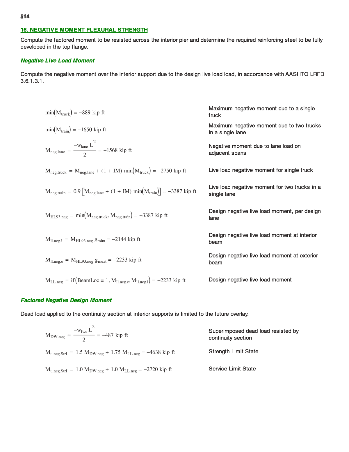
514 16. NEGATIVE MOMENT FLEXURAL STRENGTH Compute the factored moment to be resisted across the interior pier and determine the required reinforcing steel to be fully developed in the top flange. Negative Live Load Moment Compute the negative moment over the interior support due to the design live load load, in accordance with AASHTO LRFD 3.6.1.3.1. Maximum negative moment due to a single truckmin Mtruck 889 kip ft Maximum negative moment due to two trucks in a single lanemin Mtrain 1650 kip ft Negative moment due to lane load on adjacent spansMneg.lane wlane L 2 2 1568 kip ft Mneg.truck Mneg.lane 1 IM( ) min Mtruck 2750 kip ft Live load negative moment for single truck Live load negative moment for two trucks in a single laneMneg.train 0.9 Mneg.lane 1 IM( ) min Mtrain 3387 kip ft Design negative live load moment, per design laneMHL93.neg min Mneg.truck Mneg.train 3387 kip ft Design negative live load moment at interior beamMll.neg.i MHL93.neg gmint 2144 kip ft Design negative live load moment at exterior beamMll.neg.e MHL93.neg gmext 2233 kip ft MLL.neg if BeamLoc 1= Mll.neg.e Mll.neg.i 2233 kip ft Design negative live load moment Factored Negative Design Moment Dead load applied to the continuity section at interior supports is limited to the future overlay. Superimposed dead load resisted by continuity sectionMDW.neg wfws L 2 2 487 kip ft Mu.neg.StrI 1.5 MDW.neg 1.75 MLL.neg 4638 kip ft Strength Limit State Mu.neg.StrI 1.0 MDW.neg 1.0 MLL.neg 2720 kip ft Service Limit State
515 Reinforcing Steel Requirement in the Top Flange for Strength Reduction factor for strength in tension- controlled reinforced concrete (5.5.4.2)Ï f 0.90 bc b1 26 in Width of compression block at bottom flange Distance to centroid of negative moment steel, taken at mid-depth of top flangednms h tsac 0.5 tflange tsac 37 in Factored load, in terms of stress in concrete at depth of steel, for computing steel requirement Ru Mu.neg.StrI Ï f bc dnms 2 1.019 ksi m fy 0.85 f'c 8.824 Steel-to-concrete strength ratio Ïreq 1 m 1 1 2 m Ru fy 0.0185 Required negative moment steel ratio Anms.req Ïreq bc dnms 17.787 in 2 Required negative moment steel in top flange Full-length longitudinal reinforcement to be made continuous across jointAs.long.t 2.0 in 2 As.long.b 2.0 in 2 Additional negative moment reinforcing bar areaAbar 0.44 in 2 Additional reinforcement area required in the top mat (2/3 of total)Anms.t 2 3 Anms.req As.long.t 9.858 in 2 nbar.t ceil Anms.t Abar 23 Additional bars required in the top mat Additional reinforcement area required in the bottom matAnms.b 1 3 Anms.req As.long.b 3.929 in 2 nbar.b ceil Anms.b Abar 9 Additional bars required in the top mat sbar.top S Wj 6 in nbar.t 1 3.788 in Spacing of bars in top mat As.nms nbar.t nbar.b Abar As.long.t As.long.b 18.08 in 2 Total reinforcing steel provided over pier a As.nms fy 0.85 f'c bc 6.136 in Depth of compression block Mr.neg Ïf As.nms fy dnms a 2 2761 kip ft Factored flexural resistance at interior pier DCneg.mom Mu.neg.StrI Mr.neg 0.985 CheckNegMom if DCneg.mom 1.0 "OK" "No Good" "OK" Negative flexure resistance check
516 ABC SAMPLE CALCULATION â 3a Precast Pier Design for ABC (70â Span Straddle Bent)
517 PRECAST PIER DESIGN FOR ABC (70' SPAN STRADDLE BENT) BNofBm Total Number of Beams in Backward Span= BSpan Backward Span Length= BDeckW Out to Out Backward Span Deck Width= BBmAg Backward Span Beam X Sectional Area= BBmFlange Backward Span Beam Top Flange Width= BHaunch Backward Span Haunch Thickness= BBmD Backward Span Beam Depth or Height= BBmIg Backward Span Beam Moment of Inertia= yBt Backward Span Beam Top Distance from cg= NofCol Number of Columns per Bents= NofDs Number of Drilled Shaft per Bents= wCol Width of Column Section= bCol Breadth of Column Section= DsDia Drilled Shaft Diameter= HCol Height of Column= wEarWall Width of Ear Wall= hEarWall Height of Ear Wall= tEarWall Thickness of Ear Wall= tSWalk Thickness of Side Walk= bSWalk Breadth of Side Walk= BmMat Beam Material either Steel or Concrete= hbS Bottom Solid Height at Foam= htS Top Solid Height at Foam= γst Unit Weight of Steel= γc wc Unit Weight of Concrete= FNofBm = Total Number of Beams in Forward Span FSpan = Forward Span Length FDeckW = Out to Out Forward Span Deck Width FBmAg = Forward Span Beam X Sectional Area FBmFlange = Forward Span Beam Top Flange Width FHaunch = Forward Span Haunch Thickness FBmD = Forward Span Beam Depth or Height FBmIg = Forward Span Beam Moment of Inertia yFt = Forward Span Beam Top Distance from cg SlabTh = Slab Thickness RailWt = Railing Weight RailH = Railing Height RailW = Rail Base Width LeftOH = Left Overhang Distance RightOH = Right Overhang Distance DeckW = Out to Out Deck Width at Bent RoadW = Roadway Width BrgTh = Bearing Pad Thickness Bearing Seat Thickness NofLane = Number of Lanes wCap = Cap Width hCap = Cap Depth CapL = Cap Length wFoam = Width of Foam for Blockout hFoam = height of Foam for Blockout LFoam = Length Foam for Blockout
518 SlabDCInt Dead Load for Slab per Interior Beam= SlabDCExt Dead Load for Slab per Exterior Beam= BeamDC Self Weight of Beam= HaunchDC Dead Load of Haunch Concrete per Beam= RailDC Weight of Rail per Beam= FSuperDCInt Half of Forward Span Super Structure Dead Load Component per Interior Beam= FSuperDCExt Half of Forward Span Super Structure Dead Load Component per Exterior Beam= FSuperDW Half of Forward Span Overlay Dead Load Component per Beam= BSuperDCInt Half of Backward Span Super Structure Dead Load Component per Interior Beam= BSuperDCExt Half of Backward Span Super Structure Dead Load Component per Exterior Beam= BSuperDW Half of Backward Span Overlay Dead Load Component per Beam= TorsionDCInt DeadLoad Torsion in a Cap due to difference in Forward and Backward span length per Interior Beam= TorsionDCExt DeadLoad Torsion in a Cap due to difference in Forward and Backward span length per Exterior Beam= TorsionDW DW Torsion in a Cap due to difference in Forward and Backward span length per Beam= DiapWt Weight of Diaphragm= tBrgSeat Thickness of Bearing Seat= bBrgSeat Breadth of Bearing Seat=
519 Note: Use of Light-Weight-Concrete (LWC) may be considered to reduce the weight of the pier cap instead of styrofoam blockouts.
520 FORWARD SPAN PARAMETER INPUT: FNofBm 12 FSpan 70 ft FDeckW 283 6 ft FBmAg 29.1 in2 FBmFlange 10.5 in yFt 14.85 inFHaunch 0 in FBmD 29.7 in FBmIg 3990 in4 BACKWARD SPAN PARAMETER INPUT: BNofBm 12 BSpan 70 ft BDeckW 283 6 ft BBmAg 29.1 in2 BBmFlange 10.5 in yBt 14.85 inBHaunch 0 in BBmD 29.7 in BBmIg 3990 in4 COMMON BRIDGE PARAMETER INPUT: Intermediate Bent between Forward and Backward span Parameters SlabTh 9 in Overlay 25 psf θ 0 deg DeckOH 1.75 ft BrgTh 3.5 in RailWt 0.43 klf RailW 19 in RailH 34.0 in tBrgSeat 0 in bBrgSeat 0 ft DeckW 283 6 ft NofLane 3 m 0.85 wc 0.150 kcf f'c 5 ksi Cap( ) wCap 4.5 ft hCap 5 ft CapL 47 ft NofDs 2 DsDia 6 ft wCol 4 ft bCol 4 ft NofCol 2 HCol 22.00 ft f'cs 4 ksi Slab( ) γc 0.150 kcf ebrg 13 in NofBm 12 Sta 0.25 ft incr DiapWt 0.2 kip wEarWall 0 ft hEarWall 0 ft tEarWall 0 in IM 0.33 BmMat Steel LFoam 35 ft wFoam 14 in hFoam 31 in hbS 15 in (Bottom Solid Depth of Section) Es 29000 ksi γst 490 pcf steel( ) Modulus of elasticity of Concrete: E f'c 33000 wc 1.5 f'c ksi (AASHTO LRFD EQ 5.4.2.4-1 for K1 = 1) Eslab E f'cs Eslab 3834.254 ksi Ecap E f'c Ecap 4286.826 ksi Modulus of Beam or Girder: Input Beam Material, BmMat = Steel or Concrete Ebeam if BmMat Steel= Es E f'c Ebeam 29000 ksi
521 1. BENT CAP LOADING DEAD LOAD FROM SUPERSTRUCTURE: The permanent dead load components (DC) consist of slab, rail, sidewalk, haunch weight and beam self weight. Slab dead weight components will be distributed to each beam by slab tributary width between beams. Interior Beam tributary width (IntBmTriW) is taken as the average of consecutive beam spacing for a particular interior beam. Exterior Beam tributary width (ExtBmTriW) is taken as half of beam spacing plus the overhang distance. Rail, sidewalk dead load components and future wearing surface weight components (DW) can be distributed evenly among each beam. Half of DC and DW components from forward span and backward span comprise the total superstructure load or dead load reaction per beam on the pier cap or the bent cap. FORWARD SPAN SUPERSTRUCTURE DEAD LOAD: consists of 12 W30x99 Beams 12 beams were spaced 4.5' and 3'-4" alternately in forward span. For beam spacing see Typical Section Details sheet FBmSpa1 4.5 ft FBmSpa2 10 3 ft FIntBmTriW FBmSpa1 2 FBmSpa2 2 FIntBmTriW 3.917 ft FExtBmTriW FBmSpa1 2 DeckOH FExtBmTriW 4 ft RoadW 0.25 FDeckW 3 DeckW( ) 2 RailW RoadW 44 ft SlabDCInt γc FIntBmTriW SlabTh FSpan 2 SlabDCInt 15.422 kip beam SlabDCExt γc FExtBmTriW SlabTh FSpan 2 SlabDCExt 15.75 kip beam BeamDC γst FBmAg FSpan 2 BeamDC 3.466 kip beam HaunchDC γc FHaunch FBmFlange FSpan 2 HaunchDC 0 kip beam NOTE: Permanent loads such as the weight of the Rail (Barrier), Future wearing surface may be distributed uniformly among all beams if following conditions are met. Apply for live load distribution factors too. AASHTO LRFD 4.6.2.2.1 1. Width of deck is constant 2. Number of Beams >= 4 beams 3. Beams are parallel and have approximately same stiffness 4. The Roadway part of the overhang, de<= 3ft 5. Curvature in plan is < 4o 6. Bridge cross-section is consistent with one of the x-section shown in AASHTO LRFD TABLE 4.6.2.2.1-1 RailDC 2 RailWt FNofBm FSpan 2 RailDC 2.508 kip beam OverlayDW RoadW Overlay FNofBm FSpan 2 OverlayDW 3.208 kip beam
522 Forward Span Superstructure DC & DW per Interior and Exterior Beam: FSuperDCInt RailDC BeamDC SlabDCInt HaunchDC DiapWt FSuperDCInt 21.596 kip beam FSuperDCExt RailDC BeamDC SlabDCExt HaunchDC 0.5 DiapWt FSuperDCExt 21.824 kip beam FSuperDW OverlayDW FSuperDW 3.208 kip beam BACKWARD SPAN SUPERSTRUCTURE DEAD LOAD: consists of 12 W30x99 beams 12 beams were spaced 4.5' and 3'-4" alternately in backward span. For beam spacing see Typical Section Details sheet BBmSpa1 4.5 ft BBmSpa2 10 3 ft BIntBmTriW BBmSpa1 2 BBmSpa2 2 BIntBmTriW 3.917 ft BExtBmTriW BBmSpa1 2 DeckOH BExtBmTriW 4 ft RoadW 0.25 BDeckW 3 DeckW( ) 2 RailW RoadW 44 ft SlabDCInt γc BIntBmTriW SlabTh BSpan 2 SlabDCInt 15.422 kip beam SlabDCExt γc BExtBmTriW SlabTh BSpan 2 SlabDCExt 15.75 kip beam BeamDC γst BBmAg BSpan 2 BeamDC 3.466 kip beam HaunchDC γc BHaunch BBmFlange BSpan 2 HaunchDC 0 kip beam RailDC 2 RailWt BNofBm BSpan 2 RailDC 2.508 kip beam OverlayDW RoadW Overlay BNofBm BSpan 2 OverlayDW 3.208 kip beam Total Backward Span Superstructure DC & DW per Interior and Exterior Beam: BSuperDCInt RailDC BeamDC SlabDCInt HaunchDC DiapWt BSuperDCInt 21.596 kip beam BSuperDCExt RailDC BeamDC SlabDCExt HaunchDC 0.5 DiapWt BSuperDCExt 21.824 kip beam BSuperDW OverlayDW BSuperDW 3.208 kip beam
523 Total Superstructure DC & DW per Beam on Bent Cap: SuperDCInt FSuperDCInt BSuperDCInt SuperDCInt 43.192 kip beam SuperDCExt FSuperDCExt BSuperDCExt SuperDCExt 43.648 kip beam SuperDW FSuperDW BSuperDW SuperDW 6.417 kip beam TorsionDCInt max FSuperDCInt BSuperDCInt min FSuperDCInt BSuperDCInt ebrg TorsionDCInt 0 kft beam TorsionDCExt max FSuperDCExt BSuperDCExt min FSuperDCExt BSuperDCExt ebrgTorsionDCExt 0 kft beam TorsionDW max FSuperDW BSuperDW( ) min FSuperDW BSuperDW( )( ) ebrg TorsionDW 0 kft beam CAP, EAR WALL & BEARING SEAT WEIGHT: The Bent cap has two sections along the length. One is a solid rectangular section 6ft from both ends. The middle section is made hollow by placing foam blockouts in two sides of mid section as can be seen in the typical section and pier elevation figure. CapDC1 is the weight of the solid section and CapDC2 is the weight of the hollow section. CapDC1 wCap hCap γc Applicable for 0 ft CapL 6 ft( ) 41 ft CapL 47 ft( ) CapDC1 3.375 kip ft CapDC2 wCap hCap 2 wFoam hFoam( ) γc Applicable for 6 ft CapL 41 ft( ) CapDC2 2.471 kip ft EarWallDC wEarWall hEarWall tEarWall( ) γc EarWallDC 0 kip BrgSeatDC tBrgSeat bBrgSeat wCap( ) γc BrgSeatDC 0 kip beam RESULTS OF DISTRIBUTION FACTORS: Forward Span Distribution Factors: DFMFmax 0.391 (Distribution Factor for Moment) DFSFmax 0.558 (Distribution Factor for Shear) Backward Span Distribution Factors: DFMBmax 0.391 (Distribution Factor for Moment) DFSBmax 0.558 (Distribution Factor for Shear)
524 LIVE LOAD FOR SIMPLY SUPPORTED BRIDGE: HL-93 Loading: According to AASHTO LRFD 3.6.1.2.1, HL-93 consists of Design Truck + Design Lane Load or Design Tandem + Design Lane Load. Design Truck rather than Design Tandem + Design Lane Load controls the maximum Live Load Reactions at an interior bent for a span longer than 26'. For maximum reaction, place middle axle (P2 = 32 kip) of design truck over the support at a bent between the forward and the backward span and place rear axle (P3 = 32 kip) 14' away from P2 on the longer span while placing P1 14' away from P1 on either spans yielding maximum value. P1 Front Axle of Design Truck= P2 Middle Axle of Design Truck= P3 Rear Axle of Design Truck= Design Truck Axle Load: P1 8 kip P2 32 kip P3 32 kip AASHTO LRFD 3.6.1.2.2( ) TruckT P1 P2 P3 Design Lane Load: wlane 0.64 klf AASHTO LRFD 3.6.1.2.4( ) LongSpan max FSpan BSpan( ) ShortSpan min FSpan BSpan( ) Llong LongSpan Lshort ShortSpan Lane Load Reaction Lane wlane Llong Lshort 2 Lane 44.8 kip lane Truck Load Reaction Truck P2 P3 Llong 14ft Llong P1 max Llong 28ft Llong Lshort 14ft Lshort Truck 64 kip lane Maximum Live Load Reaction with Impact (LLRxn) over support on Bent: The Dynamic Load Allowance or Impact Factor, IM 0.33 AASHTO LRFD Table 3.6.2.1 1( ) LLRxn Lane Truck 1 IM( ) LLRxn 129.92 kip lane Live Load Model for Cap Loading Program: AASHTO LRFD Recommended Live Load Model For Cap Loading Program: Live Load reaction on the pier cap using distribution factors are not sufficient to design bent cap for moment and shear. Therefore, the reaction from live load is uniformly distributed to over a 10' width (which becomes W) and the reaction from the truck is applied as two concentrated loads (P and P) 6' apart. The loads act within a 12' wide traffic lane. The reaction W and the truck move across the width of the traffic lane. However, neither of the P loads can be placed closer than 2' from the edge of the traffic lane. One lane, two lanes, three lanes and so forth loaded traffic can be moved across the width of the roadway to create maximum load effects. Load on one rear wheel out of rear axle of the truck with Impact: P 0.5 P3 1 IM( ) P 21.28 kip The Design Lane Load Width Transversely in a Lane wlaneTransW 10 ft AASHTO LRFD Article 3.6.1.2.1 The uniform load portion of the Live Load, kip/station for Cap Loading Program: W LLRxn 2 P( ) Sta wlaneTransW W 2.184 kip incr LOADS generated above will be placed into a CAP LOADING PROGRAM to obtain moment and shear values for Bent Cap.
525 Torsion on Bent Cap per Beam and per Drilled Shaft: Torsional load about center line of bent cap occurs due to horizontal loads acting on the superstructure perpendicular to the bent length or along the bridge length. Braking force, Centrifugal force, WS on superstructure, and WL cause torsion on bent. In addition, torque about center line of bent cap for the dead load reaction on beam brg location occurs due to differences in forward and backward span length and eccentricity between center line of bent cap and brg location. Torsion can be neglected if Tu<0.25 Tcr (AASHTO LRFD 5.8.2.1). The maximum torsional effects on the pier cap will be obtained from RISA frame analysis under loading as stated in AASHTO LRFD SECTION 3 for different load combinations using AASHTO LRFD Table 3.4.1-1. 2. BENT CAP FLEXURAL DESIGN FLEXURAL DESIGN OF BENT CAP: h( ) b( ) f'c 5.0 ksi fy 60 ksi Es 29000 ksi Ïm 0.9 Ïv 0.9 Ïn 1 γc 0.150 kcf bcover 2 in tcover 2 in h 5 ft b 4.5 ft Ec Ecap n round Es Ec 0 (AASHTO LRFD 5.7.1) n 7 EIcap1 Ec b h3 12 Applicable for 0 CapL 6 41 CapL 47 EIcap1 2.894 10 7 kip ft2 ycg2 wCap hCap hCap 2 2 wFoam hFoam( ) hFoam 2 hbS wCap hCap 2 wFoam hFoam( ) (ycg of from Bottom of Cap Section) ycg2 29.817 in
526 Icap2 wCap hCap3 12 wCap hCap hCap 2 ycg2 2 2 wFoam hFoam3 12 wFoam hFoam hFoam 2 hbS ycg2 2 Icap2 902191.259 in 4 EIcap2 Ec Icap2 Applicable for 6 CapL 41 EIcap2 2.686 10 7 kip ft2 OUTPUT of BENT CAP LOADING PROGRAM: The maximum load effects from different applicable limit states: DEAD LOAD MdlPos 3309.6 kft MdlNeg 30.1 kft SERVICE I MsPos 5377.1 kft MsNeg 45.1 kft STRENGTH I MuPos 7830.6 kft MuNeg 64.6 kft FLEXURE DESIGN: MINIMUM FLEXURAL REINFORCEMENT AASHTO LRFD 5.7.3.3.2 Factored Flexural Resistance, Mr, must be greater than or equal to the lesser of 1.2Mcr or 1.33 Mu. Applicable to both positive and negative moment. Modulus of rupture fr 0.37 f'c ksi (AASHTO LRFD EQ 5.4.2.6) fr 0.827 ksi S Icap2 ycg2 (Bottom Section Modulus for Positive Moment) S 30257.581 in3 Cracking moment Mcr S fr (AASHTO LRFD EQ 5.7.3.3.2-1) Mcr 2086.122 kip ft Mcr1 1.2 Mcr Mcr1 2503.346 kip ft Mcr2 1.33 max MuPos MuNeg Mcr2 10414.698 kip ft Mcr_min min Mcr1 Mcr2 Therefore Mr must be greater than Mcr_min 2503.346 kip ft Moment Capacity Design (Positive Moment, Bottom Bars B) AASHTO LRFD 5.7.3.2 Bottom Steel arrangement for the Cap: Input no. of total rebar in a row from bottom of cap up to 12 rows (in unnecessary rows input zero) Np 9 9 9 0 0 0 0 0 0 0 0 0( ) Input area of rebar corresponding to above rows from bottom of cap, not applicable for mixed rebar in a single row Abp 1.56 1.56 1.56 0 0 0 0 0 0 0 0 0( ) in 2 Input center to center vertical distance between each rebar row starting from bottom of cap clp 3.5 4 4 0 0 0 0 0 0 0 0 0( ) in
527 nsPos 3 (No. of Bottom or Positive Steel Layers) Distance from centroid of positive rebar to extreme bottom tension fiber (dcPos): dcPos Ayp0 0 in dcPos 7.5 in Effective depth from centroid of bottom rebar to extreme compression fiber (dPos): dPos h dcPos dPos 52.5 in Compression Block depth under ultimate load AASHTO LRFD 5.7.2.2 β1 min 0.85 max 0.65 0.85 0.05 ksi f'c 4 ksi β1 0.8 The Amount of Bottom or Positive Steel As Required, AsReq 0.85 f'c b dPos fy 1 1 2 MuPos 0.85 Ïm f'c b dPos 2 AsReq 36.454 in 2 The Amount of Positive As Provided, NofBarsPos Np NofBarsPos 27 AsPos Ayp0 1 in 2 AsPos 42.12 in 2 htS h hFoam hbS (Top solid depth) htS 14 in Compression depth under ultimate load cPos AsPos fy 0.85 f'c β1 b (AASHTO LRFD EQ 5.7.3.1.1-4) cPos 13.765 in aPos β1 cPos aPos htS OK (AASHTO LRFD 5.7.3.2.2) aPos 11.012 in Nominal flexural resistance: MnPos AsPos fy dPos aPos 2 (AASHTO LRFD EQ 5.7.3.2.2-1) MnPos 9896.961 kip ft Tension controlled resistance factor for flexure ÏmPos min 0.65 0.15 dPos cPos 1 0.9 (AASHTO LRFD EQ 5.5.4.2.1-2) ÏmPos 0.9
528 or simply use, Ïm 0.9 (AASHTO LRFD 5.5.4.2) MrPos ÏmPos MnPos (AASHTO LRFD EQ 5.7.3.2.1-1) MrPos 8907.265 kip ft MuPos 7830.6 kip ft MinReinChkPos if MrPos Mcr_min "OK" "NG" MinReinChkPos "OK" UltimateMomChkPos if MrPos MuPos "OK" "NG" UltimateMomChkPos "OK" Moment Capacity Design (Negative Moment, Top Bars A) AASHTO LRFD 5.7.3.2 Top Steel arrangement for the Cap: Input no. of total rebar in a row from top of cap up to 12 rows (in unnecessary rows input zero) Nn 6 6 0 0 0 0 0 0 0 0 0 0( ) Input area of rebar corresponding to above rows from top of cap, not applicable for mixed rebar in a single row Abn 0.6 1.27 0 0 0 0 0 0 0 0 0 0( ) in 2 Input center to center vertical distance between each rebar row starting from top of cap cln 3.5 4 0 0 0 0 0 0 0 0 0 0( ) in nsNeg 2 (No. of Negative or Top Steel Layers) Distance from centroid of negative rebar to top extreme tension fiber (dcNeg): dcNeg Ayn0 0 in dcNeg 6.217 in Effective depth from centroid of top rebar to extreme compression fiber (dNeg): dNeg h dcNeg dNeg 53.783 in The Amount of Negative As Required, AsReq 0.85 f'c b dNeg fy 1 1 2 MuNeg 0.85 Ïm f'c b dNeg 2 AsReq 0.267 in 2 The Amount of Negative As Provided, NofBarsNeg Nn NofBarsNeg 12 AsNeg Ayn0 1 in 2 AsNeg 11.22 in 2
529 Compression depth under ultimate load cNeg AsNeg fy 0.85 f'c β1 b cNeg 3.667 in aNeg β1 cNeg aNeg 2.933 in Thus, nominal flexural resistance: MnNeg AsNeg fy dNeg aNeg 2 MnNeg 2934.97 kip ft Factored flexural resistance MrNeg Ïm MnNeg MrNeg 2641.473 kip ft MuNeg 64.6 kip ft MinReinChkNeg if MrNeg Mcr_min "OK" "NG" MinReinChkNeg "OK" UltimateMomChkNeg if MrNeg MuNeg "OK" "NG" UltimateMomChkNeg "OK" Control of Cracking at Service Limit State AASHTO LRFD 5.7.3.4 exposure_cond 1 (for exposure condition, input Class 1 = 1 and Class 2 = 2) γe if exposure_cond 1= 1 0.75( ) (Exposure condition factor) γe 1 sidecTop sidecBot 5.625 4.75( ) in (Input side cover for Top and Bottom Rebars) Positive Moment (Bottom Bars B) To find Smax: S is spacing of first layer of rebar closest to tension face n round Es Ec 0 (modular ratio) n 7 ÏPos AsPos b dPos ÏPos 0.0149 kPos ÏPos n 1 2 1 ÏPos n kPos 0.364(Applicable for Solid Rectangular Section) kdP kPos dPos Location of NA from Top of Cap for Pos Moment kdP 19.098 in StressBlockPos if kdP htS "T-Section" "Rec-Section" StressBlockPos "T-Section" Com ression Force = Tension Force OR Moment of Com ression Area = Moment of Tension Area about NA b kdPos 2 2 wFoam kdPos hStop 2 2 n AsPos dPos kdPos=
530 b 2 wFoam( ) kdPos 2 2 n AsPos 4 wFoam hStop kdPos 2 wFoam hStop 2 n AsPos dPos 0= kdPos 2 n AsPos 4 wFoam htS 2 n AsPos 4 wFoam htS 2 4 b 2 wFoam( ) 2 wFoam htS 2 n AsPos dPos 2 b 2 wFoam( ) kdPos 19.405 in Location of NA from Top of Cap Location of Resultant Compression force from NA for Positive Moment: xPos b kdPos 2 3 2 3 wFoam kdPos htS 2 1 htS kdPos 1 2 b kdPos wFoam kdPos htS 1 htS kdPos xPos 13.328 in jdPos dPos kdPos xPos jdPos 46.423 in Tensile Stress at Service Limit State fssPos MsPos AsPos jdPos fssPos 33 ksi dc1Pos clp0 0 (Distance of bottom first row rebar closest to tension face) dc1Pos 3.5 in βsPos 1 dc1Pos 0.7 h dc1Pos βsPos 1.088 smaxPos 700 kip in γe βsPos fssPos 2 dc1Pos AASHTO LRFD EQ (5.7.3.4-1) smaxPos 12.488 in sActualPos b 2 sidecBot Np0 0 1 (Equal horizontal spacing of bottom first rebar row closest to tension face) sActualPos 5.563 in Actual Max Spacing Provided in Bottom first row closest to Tension Face, saPosProvided 7 in sActualPos max saPosProvided sActualPos sActualPos 7 in SpacingCheckPos if smaxPos sActualPos "OK" "NG" SpacingCheckPos "OK"
531 Negative Moment (Top Bars A) ÏNeg AsNeg b dNeg ÏNeg 3.863 10 3 kNeg ÏNeg n 1 2 1 ÏNeg n (Applicable for Solid Rectangular Section) kNeg 0.207 kdN kNeg dNeg Location of NA from Bottom of Cap for Neg Moment kdN 11.138 in StressBlockNeg if kdN hbS "T-Section" "Rec-Section" StressBlockNeg "Rec-Section" jNeg 1 kNeg 3 jNeg 0.931 fssNeg MsNeg AsNeg jNeg dNeg fssNeg 0.963 ksi dc1Neg cln0 0 (Distance of top first row rebar closest to tension face) dc1Neg 3.5 in βsNeg 1 dc1Neg 0.7 h dc1Neg βsNeg 1.088 smaxNeg 700 kip in γe βsNeg fssNeg 2 dc1Neg smaxNeg 660.561 in sActualNeg b 2 sidecTop Nn0 0 1 (Equal horizontal spacing of top first rebar row closest to tension face) sActualNeg 8.55 in Actual Max Spacing Provided in Top first row closest to Tension Face, saNegProvided 11.125 in sActualNeg max saNegProvided sActualNeg sActualNeg 11.125 in SpacingCheckNeg if smaxNeg sActualNeg "OK" "NG" SpacingCheckNeg "OK" SUMMARY OF FLEXURE DESIGN: Bottom Rebar or B Bars: use 27~#11 bars @ 9 bars in each row of 3 rows Top Rebar or A Bars: use 6~#7 bars and 6~#10 bars in first and 2nd row from top
532 SKIN REINFORCEMENT (BARS T) AASHTO LRFD 5.7.3.4 SkBarNo 8 (Size of a skin bar) Area of a skin bar, AskBar 0.79 in 2 dcTop cln dcTop 7.5 in dcBot clp dcBot 11.5 in Effective Depth from centroid of ExtremeTension Steel to Extreme compression Fiber (dl): dl max h clp0 0 h cln0 0 dl 56.5 in Effective Depth from centroid of Tension Steel to Extreme compression Fiber (de): de max dPos dNeg de 53.783 in As min AsNeg AsPos min. of negative and positive reinforcement As 11.22 in 2 dskin h dcTop dcBot dskin 41 in Skin Reinforcement Requirement: AASHTO LRFD EQ 5.7.3.4-2 AskReq if dl 3ft min 0.012 in ft dl 30 in dskin As Aps 4 0in2 AskReq 1.087 in 2 NoAskbar1 R AskReq AskBar NoAskbar1 2 per Side Maximum Spacing of Skin Reinforcement: SskMax min de 6 12 in AASHTO LRFD 5.7.3.4 SskMax 8.964 in NoAskbar2 if dl 3ft R dskin SskMax 1 1 NoAskbar2 4 per Side NofSideBarsreq max NoAskbar1 NoAskbar2 NofSideBarsreq 4 SskRequired dskin 1 NofSideBarsreq SskRequired 8.2 in NofSideBars 5 (No. of Side Bars Provided) SskProvided dskin 1 NofSideBars SskProvided 6.833 in SskChk if SskProvided SskMax "OK" "N.G." SskChk "OK" Therefore Use: NofSideBars 5 and Size SkBarNo 8
533 3. BENT CAP SHEAR AND TORSION DESIGN SHEAR DESIGN OF CAP: Effective Shear Depth, dv max de a 2 0.9 de 0.72 h = (AASHTO LRFD 5.8.2.9) dv Distance between the resultants of tensile and compressive Force= ds Effective depth from cg of the nonprestressed tensile steel to extreme compression fiber= dp Effective depth from cg of the prestressed tendon to extreme compression fiber= de Effective depth from centroid of the tensile force to extreme compression fiber at critical shear Location= θ Angle of inclination diagonal compressive stress= Ao Area enclosed by shear flow path including area of holes therein= Ac Area of concrete on flexural tension side of member shown in AASHTO LRFD Figure 5.8.3.4.2 1= Aoh Area enclosed by centerline of exterior closed transverse torsion reinforcement including area of holes therein= Total Pos Flexural Steel Area, As AsPos As 42.12 in 2 Nominal Flexure, Mn MnPos Mn 9896.961 kft Stress block Depth, a aPos a 11.012 in Effective Depth, de dPos de 52.5 in Effective web Width at critical Location, bv b bv 4.5 ft Input initial θ 35 deg cotθ cot θ( ) Shear Resistance Factor, Ïv 0.9 Cap Depth & Width, h 60 in b 54 in Moment Arm, de a 2 46.994 in 0.9 de 47.25 in 0.72 h 43.2 in Effective Shear Depth at Critical Location, dv max de a 2 0.9 de 0.72 h (AASHTO LRFD 5.8.2.9) dv 47.25 in
534 hh h tcover bcover (Height of shear reinforcement) hh 56 in bh b 2 bcover (Width of shear reinforcement) bh 50 in ph 2 hh bh (Perimeter of shear reinforcement) ph 212 in Aoh hh bh (Area enclosed by the shear reinforcement) Aoh 2800 in 2 Ao 0.85 Aoh (AASHTO LRFD C5.8.2.1) Ao 2380 in 2 Ac 0.5 b h AASHTO LRFD FIGURE 5.8.3.4.2 1( ) Ac 1620 in 2 Yield strength & Modulus of Elasticity of Steel Reinforcement: fy Es 60 29000( ) ksi AASHTO LRFD 5.4.3.1 5.4.3.2( ) Input Mu, Tu, Vu, Nu for the critical section to be investigated: (Loads from Bent Cap & RISA Analysis) Mu Tu 1314.8 964.6( ) kft Vu Nu 665.4 0( ) kip M'u max Mu Vu Vp dv AASHTO LRFD B5.2 M'u 2620.013 kip ft V'u Vu 2 0.9 ph Tu 2 Ao 2 (Equivalent shear) AASHTO LRFD EQ (5.8.2.1-6) for solid section V'u 811.194 kip Assuming at least minimum transverse reinforcement is provided (Always provide min. transverse reinf.) εx M'u dv 0.5 Nu 0.5 V'u Vp cotθ Aps fpo 2 Es As Ep Aps = (Strain from Appendix B5) AASHTO LRFD EQ (B5.2-1) vu Vu Ïv Vp Ïv bv dv (Shear Stress) AASHTO LRFD EQ (5.8.2.9-1) vu 0.29 ksi r max 0.075 vu f'c (Shear stress ratio) r 0.075
535 After Interpolating the value of Î Î( ) Î 30.773 deg Î 2.572 Nominal Shear Resistance by Concrete, Vc 0.0316 Î f'c ksi bv dv AASHTO LRFD EQ (5.8.3.3-3) Vc 463.7 kip Vu 665.4 kip 0.5 Ïv Vc Vp 208.673 kip REGION REQUIRING TRANSVERSE REINFORCEMENT: AASHTO LRFD 5.8.2.4 Vu 0.5 Ïv Vc Vp AASHTO LRFD EQ (5.8.2.4-1) check if Vu 0.5 Ïv Vc Vp "Provide Shear Reinf" "No reinf." check "Provide Shear Reinf" Vn min Vc Vs Vp 0.25 f'c bv dv Vp = (Nominal Shear Resistance) AASHTO LRFD EQ 5.8.3.3 1 2( ) Vs Av fy dv cotθ cotα( ) sinα S = (Shear Resistance of Steel) AASHTO LRFD EQ 5.8.3.3 4( ) Vs Av fy dv cotθ S = Shear Resistance of Steel when α 90 deg=( ) AASHTO LRFD EQ (C5.8.3.3-1) Sv 6 in (Input Stirrup Spacing) Vp 0 kip Vu Vc 665.4 463.718( ) kip fy 60 ksi dv 47.25 in Î 30.773 deg (Derive from AASHTO LRFD EQ 5.8.3.3-1, C5.8.3.3-1 and Vn >= Vu)Av_req Vu Ïv Vc Vp Sv fy dv cotÎ Av_req 0.3474 in 2 Torsional Steel: At Tu 2 Ïv Ao fy cotÎ Sv (Derive from AASHTO LRFD EQ 5.8.3.6.2-1 and Tn >= Tu) At 0.161 in 2 Avt_req Av_req 2 At Shear Torsion( ) Avt_req 0.669 in 2 Avt 4 0.44 in 2 (Use 2 #6 double leg Stirrup at Sv c/c,) Provided, Avt 1.76 in 2 Avt_check if Avt Avt_req "OK" "NG" Avt_check "OK"
536 Maximum Spacing Check: AASHTO LRFD Article 5.8.2.7 Vu 665.4 kip 0.125 f'c bv dv 1594.69 kip Svmax if Vu 0.125 f'c bv dv min 0.8 dv 24 in min 0.4 dv 12 in Svmax 24 in Svmax_check if Sv Svmax "OK" "use lower spacing" Svmax_check "OK" Av Avt At (Shear Reinf. without Torsion Reinf.) Av 1.599 in 2 Vs Av fy dv cotÎ Sv Vs 1268.855 kip Minimum Transverse Reinforcement Check: AASHTO LRFD Article 5.8.2.5 bv 54 in Avmin 0.0316 f'c ksi bv Sv fy AASHTO LRFD EQ 5.8.2.5 1( ) Avmin 0.382 in 2 Avmin_check if Avt Avmin "OK" "NG" Avmin_check "OK" Maximum Nominal Shear: To ensure that the concrete in the web of beam will not crush prior to yield of shear reinforcement, LRFD Specification has given an upper limit of 0.25 f'c bv dv Vp 3189.375 kip Vc Vs Vp 1732.573 kip Vn min Vc Vs Vp 0.25 f'c bv dv Vp AASHTO LRFD EQ 5.8.3.3 1 2( ) Vn 1732.573 kip Ïv Vn 1559.316 kip Vu 665.4 kip ÏVn_check if Ïv Vn Vu "OK" "NG" ÏVn_check "OK" Torsional Resistance, Tn 2 Ao 0.5 Avt fy cotÎ Sv AASHTO LRFD EQ 5.8.3.6.2 1( ) Ïv Tn 5275.8 kip ft Longitudinal Reinforcement Requirements including Torsion: AASHTO LRFD 5.8.3.6.3 AASHTO LRFD EQ 5.8.3.6.3 1( )Applicable for solid section with Torsion Aps fps As fy M'u Ïm dv 0.5 Nu Ïn cotÎ Vu Ïv Vp 0.5 V's 2 0.45 ph Tu 2 Ïv Ao 2 Ïm Ïv Ïn 0.9 0.9 1( ) As fy Aps fps 2527.2 kip
537 M'u 2620.013 kip ft Vu 665.4 kip Nu 0 kip Vs 1268.855 kip Tu 964.6 kip ft ph 212 in Vp 0 kip As 42.12 in 2 V's min Vu Ïv Vs AASHTO LRFD 5.8.3.5 V's 739.333 kip F M'u Ïm dv 0.5 Nu Ïn cotÎ Vu Ïv Vp 0.5 V's 2 0.45 Tu ph 2 Ïv Ao 2 F 1496.141 kip Fcheck if Aps fps As fy F "OK" "NG" AASHTO LRFD EQ 5.8.3.6.3 1( ) Fcheck "OK" 4. COLUMN/DRILLED SHAFT LOADING AND DESIGN Superstructure to substructure force: AASHTO LRFD SECTION 3 LOADS and LOAD COMBINATIONS Subscript: X = Parallel to the Bent cap Length and Z = Perpendicular to the bent Cap Length th 2 in (Haunch Thickness) Beam Depth, BmH FBmD ColH HCol 0 ft (Column height + 0 ft Column Capital) TribuLength FSpan BSpan 2 Scour Depth: hscour 0 ft Scour to Fixity Depth: hscf min 3 DsDia 10 ft( ) Total Drilled Shaft height: DsH hscour hscf DsH 10 ft
538 ho BrgTh BmH th SlabTh (Top of cap to top of slab height) ho 3.683 ft h6 ho 6ft (Top of cap to top of slab height + 6 ft) h6 9.683 ft hsup BmH th SlabTh RailH (Height of Superstructure) hsup 6.225 ft h1 DsH ColH hCap 2 (Height of Cap cg from Fixity of Dshaft) h1 34.5 ft h2 DsH ColH hCap h6 h2 46.683 ft h3 DsH ColH hCap BrgTh hsup 2 h3 40.404 ft Tributary area for Superstructure, Asuper hsup( ) TribuLength( ) Asuper 435.75 ft 2 LIVE LOAD REACTIONS: LL Live load Reaction LL on cap can be taken only the vertical Rxn occurs when HL93 is on both the forward and backward span or when HL93 Loading is on one span only which causes torsion too. To maximize the torsion, LL only acts on the longer span between forward and backward span. For maximum reaction, place rear axle (P3 = 32 kip) over the support at bent while the design truck traveling along the span. Maximum Forward Span Design Truck (FTruck) & Lane Load Reaction (FLane): FTruck P3 P2 FSpan 14 ft( ) FSpan P1 FSpan 28ft( ) FSpan FTruck 62.4 kip FLane wlane FSpan 2 FLane 22.4 kip lane Forward Span Live Load Reactions with Impact (FLLRxn): FLLRxn FLane FTruck 1 IM( ) FLLRxn 105.392 kip lane Maximum Backward Span Design Truck (BTruck) & Lane Load Reaction (BLane): BTruck P3 P2 BSpan 14 ft( ) BSpan P1 BSpan 28ft( ) BSpan BTruck 62.4 kip BLane wlane BSpan 2 BLane 22.4 kip lane Backward Span Live Load Reactions with Impact (BLLRxn): BLLRxn BLane BTruck 1 IM( ) BLLRxn 105.392 kip lane Live Load Reactions per Beam with Impact (BmLLRxn) using Distribution Factors: BmLLRxn LLRxn( ) max DFSFmax DFSBmax Max reaction when mid axle on support( ) BmLLRxn 72.556 kip beam
539 FBmLLRxn FLLRxn( ) DFSFmax Only Forward Span is Loaded( ) FBmLLRxn 58.858 kip beam BBmLLRxn BLLRxn( ) DFSBmax Only Backward Span is Loaded( ) BBmLLRxn 58.858 kip beam Torsion due to the eccentricity from CL of Bearing to CL of Bent when only Longer Span is loaded with HL-93 Loading TorsionLL max FBmLLRxn BBmLLRxn( ) ebrg TorsionLL 63.763 kip ft beam Live Load Reactions per Beam without Impact (BmLLRxnn ) using Distribution Factors: BmLLRxnn (Lane Truck) max (DFSFmax DFSBmax BmLLRxnn 60.761 kip beam FBmLLRxnn FLane FTruck( ) DFSFmax FBmLLRxnn 47.358 kip beam BBmLLRxnn BLane BTruck( ) DFSBmax BBmLLRxnn 47.358 kip beam Torsion due to the eccentricity of CL of Bearing and CL of Bent without Impact TorsionLLn max FBmLLRxnn BBmLLRxnn ebrg TorsionLLn 51.305 kft beam CENTRIFUGAL FORCE: CF (AASHTO LRFD 3.6.3) Skew Angle of Bridge, θ 0 deg Design Speed v 45 mph f g( ) 4 3 32.2 ft sec 2Degree of Curve, Ïc 0.00001 deg (Input 4o curve or 0.00001o for 0o curve) Radius of Curvature, Rc 360 deg( ) 100 ft 2 Ï Ïc Rc 572957795.131 ft Rc â ft= Centri. Force Factor, C f v 2 Rc g AASHTO LRFD EQ 3.6.3 1( ) C 0 Pcf C TruckT NofLane( ) m( ) Pcf 0 kip Centrifugal force parallel to bent (X-direction) CFX Pcf cos θ( ) NofBm CFX 0 kip beam Centrifugal force normal to bent (Z-direction) CFZ Pcf sin θ( ) NofBm CFZ 0 kip beam Moments at cg of the Bent Cap due to Centrifugal Force MCF_X CFZ h6 hCap 2 MCF_X 0 kft beam MCF_Z CFX h6 hCap 2 MCF_Z 0 kft beam
540 BRAKING FORCE: BR (AASHTO LRFD 3.6.4) The braking force shall be taken as maximum of 5% of the Resultant Truck plus lane load OR 5% of the Design Tandem plus Lane Load or 25% of the design truck. Pbr1 5% Lane TruckT( ) NofLane( ) m( ) Truck Lane( ) Pbr1 14.892 kip Pbr2 5% Lane 50 kip( ) NofLane( ) m( ) Tandem Lane( ) Pbr2 12.087 kip Pbr3 25% TruckT( ) NofLane( ) m( ) DesignTruck( ) Pbr3 45.9 kip Pbr max Pbr1 Pbr2 Pbr3 Pbr 45.9 kip Braking force parallel to bent (X-direction) BRX Pbr sin θ( ) NofBm BRX 0 kip beam Braking force normal to bent (Z-direction) BRZ Pbr cos θ( ) NofBm BRZ 3.825 kip beam Moments at cg of the Bent Cap due to Braking Force MBR_X BRZ h6 hCap 2 MBR_X 46.601 kft beam MBR_Z BRX h6 hCap 2 MBR_Z 0 kft beam WATER LOADS: WA (AASHTO LRFD 3.7) Note : To be applied only on bridge components below design high water surface. Substructure: V 0 ft sec (Design Stream Velocity) Specific Weight, γwater 62.4 pcf Longitudinal Stream Pressure: AASHTO LRFD 3.7.3.1 AASHTO LRFD Table 3.7.3.1-1 for Drag Coefficient, CD semicircular-nosed pier 0.7 square-ended pier 1.4 debris lodged against the pier 1.4 wedged-nosed pier with nose angle 90 deg or less 0.8 Columns and Drilled Shafts: Longitudinal Drag Force Coefficient for Column, CD_col 1.4
541 Longitudinal Drag Force Coefficient for Drilled Shaft, CD_ds 0.7 pT CD V2 2 g γwater= (Longitudinal stream pressure) AASHTO LRFD EQ (C3.7.3.1-1) pT_col CD_col V2 2 g γwater pT_col 0 ksf pT_ds CD_ds V2 2 g γwater pT_ds 0 ksf Lateral Stream Pressure: AASHTO LRFD 3.7.3.2 AASHTO LRFD Table 3.7.3.2-1 for Lateral Drag Coefficient, CL Angle, , between direction of flow and longitudina axis of the pi e 0deg 0 5deg 0.5 10deg 0.7 20deg 0.9 >30deg 1 CL Lateral Drag Force Coefficient, CL 0.0 Lateral stream pressure, pL CL V2 2 g γwater pL 0 ksf Bent Cap: Longitudinal stream pressure CL 1.4 pTcap CL V2 2 g γwater pTcap 0 ksf WA on Columns Water force on column parallel to bent (X-direction) WAcol_X wCol pT_col WAcol_X 0 kip ft If angle between direction of flow and longitudinal axis of pile = 0 then apply load at one exterior column only otherwise apply it on all columns. WA at all columns will be distributed uniformly rather than triangular distribution on Column Height. Water force on column normal to bent (Z-direction) WAcol_Z bCol pL WAcol_Z 0 kip ft WA on Drilled Shafts Water force on drilled shaft parallel to bent (X-direction) WAdshaft_X DsDia pT_ds WAdshaft_X 0 kip ft Water force on drilled shaft normal to bent (Z-direction) WAdshaft_Z DsDia pL WAdshaft_Z 0 kip ft
542 WA on Bent Cap (input as a punctual load) Water force on bent cap parallel to bent (X-direction) WAcap_X wCap hCap pTcap (If design HW is below cap then input zero) WAcap_X 0 kip Water force on bent cap normal to bent (Z-direction) WAcap_Z hCap pL (If design HW is below cap then input zero) WAcap_Z 0 kip ft WIND ON SUPERSTRUCTURE: WS (AASHTO LRFD 3.8.1.2.2) Note : Wind Loads to be applied only on bridge exposed components above water surface AASHTO LRFD Table 3.8.1.2.2-1 specifies the wind load components for various angles of attack. In order to simplify the analysis, this calculation considers as default values those for girders which generate the maximum effect on structure. The results can be considered as conservative. For a superstructure other than a girder type and/or for a more detailed analysis, use the proper values as specified in the above mentioned table. AASHTO LRFD table 3.8.1.2.2-1 (modified) If the bridge is approximately 30â high and local wind velocities are known to be less than 100 mph, wind load for this bridge should be from AASHTO LRFD TABLE 3.8.2.2-1. Otherwise use AASHTO LRFD EQ 3.8.1.2.1-1 as mentioned above. ptsup 0.05ksf Normal to superstructure (conservative suggested value 0.050 ksf) plsup 0.012ksf Along Superstructure (conservative suggested value 0.019 ksf) WSchk if ptsup hsup 0.3 klf "OK" "N.G." WSchk "OK" WsupLong plsup hsup TribuLength NofBm WsupLong 0.436 kip beam WsupTrans ptsup hsup TribuLength NofBm WsupTrans 1.816 kip beam Wind force on superstructure parallel to bent (X-direction) WSsuper_X WsupLong sin θ( ) WsupTrans cos θ( ) WSsuper_X 1.816 kip beam Wind force on superstructure normal to bent (Z-direction) WSsuper_Z WsupLong cos θ( ) WsupTrans sin θ( ) WSsuper_Z 0.436 kip beam Moments at cg of the Bent Cap due to Wind load on superstructure Msuper_X WSsuper_Z hCap 2 BrgTh hsup 2 Msuper_X 2.573 kft beam
543 Msuper_Z WSsuper_X hCap 2 BrgTh hsup 2 Msuper_Z 10.72 kft beam WIND ON SUBSTRUCTURE: WS (AASHTO LRFD 3.8.1.2.3) Base Wind pressure, psub 0.04 ksf will be applied on exposed substructure both transverse & longitudinal direction Wind on Columns Wind force on columns parallel to bent (X-direction) WScol_X psub bCol cos θ( ) wCol sin θ( )( ) WScol_X 0.16 kip ft Apply WS loads at all columns even with zero degree attack angle. Wind force on columns normal to bent (Z-direction) WScol_Z psub bCol sin θ( ) wCol cos θ( )( ) WScol_Z 0.16 kip ft Wind on Bent Cap & Ear Wall WSew_X psub hEarWall wEarWall sin θ( ) wCap cos θ( )( ) WSew_X 0 kip WSew_Z psub hEarWall wEarWall cos θ( ) wCap sin θ( )( ) WSew_Z 0 kip Wind force on bent cap parallel to bent (X-direction) WScap_X psub hCap CapL sin θ( ) wCap cos θ( )( ) WSew_X (punctual load) WScap_X 0.9 kip Wind force on bent cap normal to bent (Z-direction) WScap_Z psub hCap CapL cos θ( ) wCap sin θ( )( ) WSew_Z CapL WScap_Z 0.2 kip ft WIND ON VEHICLES: WL (AASHTO LRFD 3.8.1.3) AASHTO LRFD Table 3.8.1.3-1 specifies the wind on live load components for various angles of attack. In order to simplify the analysis, this calculation considers as default values the maximum wind components as defined in the above mentioned table. The results can be considered conservative. For a more detailed analysis, use the proper skew angle according to the table. AASHTO LRFD table 3.8.1.3-1 (suggested value 0.1 kip/ft) pWLt 0.1 kip ft (suggested value 0.038 kip/ft) pWLl 0.04 kip ft
544 WLPar pWLl TribuLength NofBm WLPar 0.233 kip beam WLNor pWLt TribuLength NofBm WLNor 0.583 kip beam Wind force on live load parallel to bent (X-direction) WLX WLNor cos θ( ) WLPar sin θ( ) WLX 0.583 kip beam Wind force on live load normal to bent (Z-direction) WLZ WLNor sin θ( ) WLPar cos θ( ) WLZ 0.233 kip beam Moments at cg of the Bent Cap due to Wind load on Live Load MWL_X WLZ h6 hCap 2 MWL_X 2.843 kft beam MWL_Z WLX h6 hCap 2 MWL_Z 7.107 kft beam Vertical Wind Pressure: (AASHTO LRFD 3.8.2) DeckWidth FDeckW Bridge deck width including parapet and sidewalk Puplift 0.02ksf( ) DeckWidth TribuLength (Acts upword Y-direction) Puplift 66.033 kip Applied at the windward quarter-point of the deck width. Note: Applied only for Strength III and for Service IV for minimum permanent loads only. (AASHTO LRFD table 3.4,1-2, factors for permanent loads) Load Combinations: using AASHTO LRFD Table 3.4.1-1 STRENGTH_I 1.25 DC 1.5 DW 1.75 LL BR CF( ) 1.0 WA= STRENGTH_IA 0.9 DC 0.65 DW 1.75 LL BR CF( ) 1.0 WA= STRENGTH_III 1.25 DC 1.5 DW 1.4 WS 1.0 WA 1.4 Puplift= STRENGTH_IIIA 0.9 DC 0.65 DW 1.4 WS 1.0 WA 1.4 Puplift= STRENGTH_V 1.25 DC 1.5 DW 1.35 LL BR CF( ) 0.4 WS 1.0 WA 1.0 WL= STRENGTH_VA 0.9 DC 0.65 DW 1.35 LL BR CF( ) 0.4 WS 1.0 WA 1.0 WL= SERVICE_I 1.0 DC 1.0 DW 1.0 LLno_Impact BR CF 0.3 WS 1.0 WA 1.0 WL=
545 All these loadings as computed above such as DC, DW, LL, WL, WA, WS etc. are placed on the bent frame composed of bent cap and columns and drilled shafts. The frame is analyzed in RISA using load combinations as stated above. Output Loadings for various load combinations for column and drilled shaft are used to run PCA Column program to design the columns. It is found that 4'X4' Column with 20~#11 bars is sufficient for the loadings. Drilled shaft or other foundation shall be designed for appropriate loads. Total Vertical Foundation Load at Service I Limit State: Forward Span Superstructure DC (FFDC) & DW (FFDW): FFDC FNofBm 2( ) FSuperDCInt 2 FSuperDCExt FFDC 259.607 kip FFDW FNofBm( ) FSuperDW FFDW 38.5 kip Backward Span Superstructure DC (FBDC) & DW (FBDW): FBDC BNofBm 2( ) BSuperDCInt 2 BSuperDCExt FBDC 259.607 kip FBDW BNofBm( ) BSuperDW FBDW 38.5 kip Total Cap Dead Load Weight (TCapDC): CapDC CapDC1 CapL LFoam( ) CapDC2 LFoam CapDC 126.979 kip TCapDC CapDC NofBm( ) BrgSeatDC( ) EarWallDC TCapDC 126.979 kip Total DL on columns including Cap weight (FDC): FDL FFDC FFDW FBDC FBDW TCapDC FDL 723.194 kip Column & Drilled Shaft Self Weight: DShaft Length, DsHt 0 ft if Rounded Col, ColDia 0 ft ColDC if ColDia 0ft Ï 4 ColDia( )2 HCol( ) γc wCol bCol HCol γc Column Wt, ColDC 52.8 kip DsDC Ï 4 DsDia( )2 DsHt( ) γc Dr Shaft Wt, DsDC 0 kip Total Dead Load on Drilled Shaft (DL_on_DShaft): DL_on_DShaft FDL NofCol( ) ColDC( ) NofDs( ) DsDC( ) DL_on_DShaft 828.794 kip Live Load on Drilled Shaft: m 0.85 (Multiple Presence Factors for 3 Lanes) AASHTO LRFD Table 3.6.1.1.2 1( RLL Lane Truck( ) NofLane( ) m( ) (Total LIVE LOAD without Impact) RLL 277.44 kip
546 Total Load, DL+LL per Drilled Shaft of Intermediate Bent: Load_on_DShaft DL_on_DShaft RLL NofDs Load_on_DShaft 276.6 ton 5. PRECAST COMPONENT DESIGN Precast Cap Construction and Handling: w1 b h γc applicable for 0 ft Lcap 6 ft w1 3.375 klf (Cap selfweight) w2 b h 2 wFoam hFoam( ) γc applicable for 6 ft Lcap 41 ft w2 2.471 klf (Cap selfweight) w3 b h γc applicable for 41 ft Lcap 47 ft w3 3.375 klf (Cap selfweight) l1 6 ft l2 35 ft l3 6 ft Lcap l1 l2 l3 (Total Cap Length) Lcap 47 ft Due to the location of girder bolts, pickup points at 8' from both ends. Indeed, we can model cap lifting points as simply supported beam under self weight supported at 8' and 39' respectively from very end. l2 = 35 ftl1 = 6 ft l3 = 6 ft lc = 8 ftlb = 31 ftla = 8 ft la 8 ft lb 31 ft lc 8ft Construction factor: λcons 1.25 λcons 1.25 Maximum Positive Moment (MmaxP) & Negative Moment (MmaxN): Rxn 0.5 w1 l1 w2 l2 w3 l3 Rxn 63.49 kip MmaxP Rxn lb 2 w1 l1 l1 2 la l1 lb 2 w2 2 la l1 lb 2 2 MmaxP 190.617 kft MmaxN w1 l1 l1 2 la l1 w2 2 la l1 2 MmaxN 106.192 kft Factored Maximum Positive Moment (MuP) & Negative Moment (MuN): MuP λcons MmaxP (Positive Moment at the middle of the cap) MuP 238.271 kft MuN λcons MmaxN (Negative Moment at the support point) MuN 132.74 kft
547 Maximum Positive Stress (ftP) & Negative Stress (ftN): ftP MuP h ycg2 Icap2 ftP 95.657 psi ftN MuN ycg2 Icap2 ftN 52.644 psi Modulus of Rupture: According PCI hand book 6th edition modulus of rupture, fr = 7.5\/f'c is divided by a safety factor 1.5 in order to design a member without cracking f'c 5 ksi (Compressive Strength of Concrete) Unit weight factor, λ 1 fr 5 λ f'c psi (PCI EQ 5.3.3.2) fr 353.553 psi fr_check if fr ftP fr ftN "OK" "N.G." fr_check "OK" Precast Column Construction and Handling: wCol 4 ft (Column width) Column breadth, bCol 4 ft wcol wCol bCol γc (Column self weight) wcol 2.4 klf Due to the location of girder bolts on column, pick up points at 3' from both ends. Indeed, we can model column lifting points as simply supported beam under self weight supported at 3' and 19' respectively from very end. w = 2.4 klf lc = 3 ftlb = 16 ftla = 3 ft la 3 ft lb 16 ft lc 3 ft Maximum Positive Moment (MmaxP) & Negative Moment (MmaxN): MmaxP wcol HCol 2 HCol 4 la MmaxP 66 kft MmaxN wcol la 2 2 MmaxN 10.8 kft Factored Maximum Positive Moment (MuP) & Negative Moment (MuN): MuP λcons MmaxP MuP 82.5 kft MuN λcons MmaxN MuN 13.5 kft
548 Scol wCol bCol2 6 (Column Section Modulus) Scol 18432 in 3 Maximum Positive Stress (ftP) & Negative Stress (ftN): ftP MuP Scol ftP 53.711 psi ftN MuN Scol ftN 8.789 psi Modulus of Rupture: According PCI hand book 6th edition modulus of rupture, fr = 7.5\/f'c is divided by a safety factor 1.5 in order to design a member without cracking f'c 5 ksi (Compressive Strength of Concrete) Unit weight factor, λ 1 fr 5 λ f'c psi (PCI EQ 5.3.3.2) fr 353.553 psi fr_check if fr ftP fr ftN "OK" "N.G." fr_check "OK" DEVELOPMENT LENGTH: AASHTO LRFD 5.11 Ab 1.56 in 2 (Area of Bar) db 1.41 in (Diameter of Bar) f'c 5 ksi Modification Factor: According to AASHTO LRFD 5.11.2.1.2, the basic development length, ldb is required to multiply by the modification factor to obtain the development length ld for tension or compression. λmod 1.0 Basic Tension Development: AASHTO LRFD 5.11.2.1 for bars up to #11 ldb max 1.25 Ab in fy f'c ksi 0.4 db fy ksi 12 in (AASHTO LRFD 5.11.2.1.1) ldb 52.324 in ld λmod ldb ld 4.36 ft Basic Compression Development: AASHTO LRFD 5.11.2.2 ldb max 0.63 db fy f'c ksi 0.3 db fy ksi 8 in AASHTO LRFD EQ 5.11.2.2.1 1 2( ) ldb 25.38 in ld λmod ldb ld 2.115 ft
549 ABC SAMPLE CALCULATION â 3b Precast Pier Design for ABC (70â Conventional Pier)
550 PRECAST PIER DESIGN FOR ABC (70' SPAN CONVENTIONAL PIER) FNofBm Total Number of Beams in Forward Span= BNofBm Total Number of Beams in Backward Span= FSpan Forward Span Length= BSpan Backward Span Length= FDeckW Out to Out Forward Span Deck Width= BDeckW Out to Out Backward Span Deck Width= FBmAg Forward Span Beam X Sectional Area= BBmAg Backward Span Beam X Sectional Area= FBmFlange Forward Span Beam Top Flange Width= BBmFlange Backward Span Beam Top Flange Width= FHaunch Forward Span Haunch Thickness= BHaunch Backward Span Haunch Thickness= FBmD Forward Span Beam Depth or Height= BBmD Backward Span Beam Depth or Height= FBmIg Forward Span Beam Moment of Inertia= BBmIg Backward Span Beam Moment of Inertia= yFt Forward Span Beam Top Distance from cg= yBt Backward Span Beam Top Distance from cg= NofCol Number of Columns per Bent=SlabTh Slab Thickness= NofDs Number of Drilled Shaft per Bent=RailWt Railing Weight= wCol Width of Column Section=RailH Railing Height= bCol Breadth of Column Section=RailW Rail Base Width= DsDia Drilled Shaft Diameter=DeckOH Deck Overhang Distance= HCol Height of Column=DeckW Out to Out Deck Width at Bent= wEarWall Width of Ear Wall=RoadW Roadway Width= hEarWall Height of Ear Wall=BrgTh Bearing Pad Thickness Bearing Seat Thickness= tEarWall Thickness of Ear Wall=NofLane Number of Lanes= tSWalk Thickness of Side Walk= wCap Cap Width= bSWalk Breadth of Side Walk=hCap Cap Depth= CapL Cap Length= BmMat Beam Material either Steel or Concrete= γc Unit Weight of Concrete= DiapWt Weight of Diaphragm= wc Unit Weight of Concrete= γst Unit Weight of Steel= SlabDCInt Dead Load for Slab per Interior Beam=
551 SlabDCExt Dead Load for Slab per Exterior Beam= BeamDC Self Weight of Beam= HaunchDC Dead Load of Haunch Concrete per Beam= RailDC Weight of Rail per Beam= FSuperDCInt Half of Forward Span Super Structure Dead Load Component per Interior Beam= FSuperDCExt Half of Forward Span Super Structure Dead Load Component per Exterior Beam= FSuperDW Half of Forward Span Overlay Dead Load Component per Beam= BSuperDCInt Half of Backward Span Super Structure Dead Load Component per Interior Beam= BSuperDCExt Half of Backward Span Super Structure Dead Load Component per Exterior Beam= BSuperDW Half of Backward Span Overlay Dead Load Component per Beam= TorsionDCInt DeadLoad Torsion in a Cap due to difference in Forward and Backward span length per Interior Beam= TorsionDCExt DeadLoad Torsion in a Cap due to difference in Forward and Backward span length per Exterior Beam= TorsionDW DW Torsion in a Cap due to difference in Forward and Backward span length per Beam= tBrgSeat Thickness of Bearing Seat= bBrgSeat Breadth of Bearing Seat=
552 Note: Use of Light Weight Concrete (LWC) may be considered to reduce the weight of the pier cap instead of using styrofoam blockouts.
553 FORWARD SPAN PARAMETER INPUT: FNofBm 12 FSpan 70 ft FDeckW 283 6 ft FBmAg 29.1 in2 FBmFlange 10.5 in yFt 14.85 inFHaunch 0 in FBmD 29.7 in FBmIg 3990 in4 BACKWARD SPAN PARAMETER INPUT: BNofBm 12 BSpan 70 ft BDeckW 283 6 ft BBmAg 29.1 in2 BBmFlange 10.5 in yBt 14.85 inBHaunch 0 in BBmD 29.7 in BBmIg 3990 in4 COMMON BRIDGE PARAMETER INPUT: Bent in Question Parameters SlabTh 9 in Overlay 25 psf θ 0 deg DeckOH 1.75 ft BrgTh 3.5 in RailWt 0.43 klf RailW 19 in RailH 34.0 in tBrgSeat 0 in bBrgSeat 0 ft DeckW 283 6 ft NofLane 3 m 0.85 wc 0.150 kcf f'c 5 ksi Cap( ) wCap 4.0 ft hCap 4.0 ft CapL 47 ft NofDs 2 DsDia 5 ft wCol 3.5 ft bCol 3.5 ft NofCol 2 HCol 22.00 ft f'cs 4 ksi Slab( ) γc 0.150 kcf ebrg 13 in NofBm 12 Sta 0.25 ft incr DiapWt 0.2 kip wEarWall 0 ft hEarWall 0 ft tEarWall 0 in IM 0.33 BmMat Steel Es 29000 ksi γst 490 pcf steel( ) Modulus of elasticity of Concrete: E f'c 33000 wc 1.5 f'c ksi (AASHTO LRFD EQ 5.4.2.4-1 for K1 = 1) Eslab E f'cs Eslab 3834.254 ksi Ecap E f'c Ecap 4286.826 ksi Modulus of Beam or Girder: Input Beam Material, BmMat = Steel or Concrete Ebeam if BmMat Steel= Es E f'c Ebeam 29000 ksi
554 1. BENT CAP LOADING DEAD LOAD FROM SUPERSTRUCTURE: The permanent dead load components (DC) consist of slab, rail, sidewalk, haunch weight and beam self weight. Slab Dead weight components will be distributed to each beam by slab tributary width between beams. Interior Beam tributary width (IntBmTriW) is taken as the average of consecutive beam spacing for a particular interior beam. Exterior Beam tributary width (ExtBmTriW) is taken as half of beam spacing plus the overhang distance. Rail, sidewalk dead load components and future wearing surface weight components (DW) can be distributed evenly among each beam. Half of DC and DW components from forward span and backward span comprise the total superstructure load or dead load reaction per beam on the pier cap or the bent cap. FORWARD SPAN SUPERSTRUCTURE DEAD LOAD: consists of 12 W30x99 Beams 12 beams were spaced 4.5' and 3'-4" alternately in forward span. For beam spacing see Typical Section Details sheet FBmSpa1 4.5 ft FBmSpa2 10 3 ft FIntBmTriW FBmSpa1 2 FBmSpa2 2 FIntBmTriW 3.917 ft FExtBmTriW FBmSpa1 2 DeckOH FExtBmTriW 4 ft RoadW 0.25 FDeckW 3 DeckW( ) 2 RailW RoadW 44 ft SlabDCInt γc FIntBmTriW SlabTh FSpan 2 SlabDCInt 15.422 kip beam SlabDCExt γc FExtBmTriW SlabTh FSpan 2 SlabDCExt 15.75 kip beam BeamDC γst FBmAg FSpan 2 BeamDC 3.466 kip beam HaunchDC γc FHaunch FBmFlange FSpan 2 HaunchDC 0 kip beam NOTE: Permanent loads such as the weight of the Rail (Barrier), Future wearing surface may be distributed uniformly among all beams if following conditions are met. Apply for live load distribution factors too. AASHTO LRFD 4.6.2.2.1 1. Width of deck is constant 2. Number of Beams >= 4 beams 3. Beams are parallel and have approximately same stiffness 4. The Roadway part of the overhang, de<= 3ft 5. Curvature in plan is < 4o 6. Bridge cross-section is consistent with one of the x-section shown in AASHTO LRFD TABLE 4.6.2.2.1-1 RailDC 2 RailWt FNofBm FSpan 2 RailDC 2.508 kip beam OverlayDW RoadW Overlay FNofBm FSpan 2 OverlayDW 3.208 kip beam
555 Forward Span Superstructure DC & DW per Interior and Exterior Beam: FSuperDCInt RailDC BeamDC SlabDCInt HaunchDC DiapWt FSuperDCInt 21.596 kip beam FSuperDCExt RailDC BeamDC SlabDCExt HaunchDC 0.5 DiapWt FSuperDCExt 21.824 kip beam FSuperDW OverlayDW FSuperDW 3.208 kip beam BACKWARD SPAN SUPERSTRUCTURE DEAD LOAD: Consists of 12 W30x99 beams 12 beams were spaced 4.5' and 3'-4" alternately in Backward span. For beam spacing see Typical Section Details sheet BBmSpa1 4.5 ft BBmSpa2 10 3 ft BIntBmTriW BBmSpa1 2 BBmSpa2 2 BIntBmTriW 3.917 ft BExtBmTriW BBmSpa1 2 DeckOH BExtBmTriW 4 ft RoadW 0.25 BDeckW 3 DeckW( ) 2 RailW RoadW 44 ft SlabDCInt γc BIntBmTriW SlabTh BSpan 2 SlabDCInt 15.422 kip beam SlabDCExt γc BExtBmTriW SlabTh BSpan 2 SlabDCExt 15.75 kip beam BeamDC γst BBmAg BSpan 2 BeamDC 3.466 kip beam HaunchDC γc BHaunch BBmFlange BSpan 2 HaunchDC 0 kip beam RailDC 2 RailWt BNofBm BSpan 2 RailDC 2.508 kip beam OverlayDW RoadW Overlay BNofBm BSpan 2 OverlayDW 3.208 kip beam Total Backward Span Superstructure DC & DW per Interior and Exterior Beam: BSuperDCInt RailDC BeamDC SlabDCInt HaunchDC DiapWt BSuperDCInt 21.596 kip beam BSuperDCExt RailDC BeamDC SlabDCExt HaunchDC 0.5 DiapWt BSuperDCExt 21.824 kip beam BSuperDW OverlayDW BSuperDW 3.208 kip beam
556 Total Superstructure DC & DW Reactions per Beam on Bent Cap: SuperDCInt FSuperDCInt BSuperDCInt SuperDCInt 43.192 kip beam SuperDCExt FSuperDCExt BSuperDCExt SuperDCExt 43.648 kip beam SuperDW FSuperDW BSuperDW SuperDW 6.417 kip beam TorsionDCInt max FSuperDCInt BSuperDCInt min FSuperDCInt BSuperDCInt ebrg TorsionDCInt 0 kft beam TorsionDCExt max FSuperDCExt BSuperDCExt min FSuperDCExt BSuperDCExt ebrgTorsionDCExt 0 kft beam TorsionDW max FSuperDW BSuperDW( ) min FSuperDW BSuperDW( )( ) ebrg TorsionDW 0 kft beam CAP, EAR WALL & BEARING SEAT WEIGHT: The bent cap has only one solid section along the length. The solid rectangular section of 4'X4' can be seen in typical section and pier elevation figure. CapDC is the weight of the section of the bent or pier cap. CapDC wCap hCap γc CapDC 2.4 klf CapDCsta wCap hCap γc Sta( ) CapDCsta 0.6 kip incr EarWallDC wEarWall hEarWall tEarWall( ) γc EarWallDC 0 kip BrgSeatDC tBrgSeat bBrgSeat wCap( ) γc BrgSeatDC 0 kip beam EIcap Ecap wCap hCap3 12 EIcap 1.317 10 7 kip ft2 RESULTS OF DISTRIBUTION FACTORS: Forward Span Distribution Factors: DFMFmax 0.391 (Distribution Factor for Moment) DFSFmax 0.558 (Distribution Factor for Shear) Backward Span Distribution Factors: DFMBmax 0.391 (Distribution Factor for Moment) DFSBmax 0.558 (Distribution Factor for Shear)
557 LIVE LOAD FOR SIMPLY SUPPORTED BRIDGE: HL-93 Loading: According to AASHTO LRFD 3.6.1.2.1 HL-93 consists of Design Truck + Design Lane Load or Design Tandem + Design Lane Load. Design Truck rather than Design Tandem + Design Lane Load controls the maximum Live Load Reactions at an interior bent for a span longer than 26'. For maximum reaction, place middle axle (P2 = 32 kip) of design truck over the support at a bent between the forward and the backward span and place rear axle (P3 = 32 kip) 14' away from P2 on the longer span while placing P1 14' away from P1 on either spans yielding maximum value. P1 Front Axle of Design Truck= P2 Middle Axle of Design Truck= P3 Rear Axle of Design Truck= Design Truck Axle Load: P1 8 kip P2 32 kip P3 32 kip AASHTO LRFD 3.6.1.2.2( ) TruckT P1 P2 P3 Design Lane Load: wlane 0.64 klf AASHTO LRFD 3.6.1.2.4( ) Longer Span Length, Llong max FSpan BSpan( ) Shorter Span Length, Lshort min FSpan BSpan( ) Lane Load Reaction: Lane wlane Llong Lshort 2 Lane 44.8 kip lane Truck Load Reaction: Truck P2 P3 Llong 14ft Llong P1 max Llong 28ft Llong Lshort 14ft Lshort Truck 64 kip lane Maximum Live Load Reaction with Impact (LLRxn) over support on Bent: The Dynamic Load Allowance or Impact Factor, IM 0.33 AASHTO LRFD Table 3.6.2.1 1( ) LLRxn Lane Truck 1 IM( ) LLRxn 129.92 kip lane Live Load Model for Cap Loading Program: AASHTO LRFD Recommended Live Load Model For Cap Loading Program: Live Load reaction on the pier cap using distribution factors are not sufficient to design bent cap for moment and shear. Therefore, the reaction from live load is uniformly distributed to over a 10' width (which becomes W) and the reaction from the truck is applied as two concentrated loads (P and P) 6' apart. The loads act within a 12' wide traffic lane. The reaction W and the truck move across the width of the traffic lane. However, neither of the P loads can be placed closer than 2' from the edge of the traffic lane. One lane, two lane, three lane and so forth loaded traffic can be moved across the width of the roadway to create maximum load effects. Load on one rear wheel out of rear axle of the truck with Impact: P 0.5 P3 1 IM( ) P 21.28 kip The Design Lane Load Width Transversely in a Lane wlaneTransW 10 ft AASHTO LRFD Article 3.6.1.2.1 The uniform load portion of the Live Load, kip/station for Cap Loading Program: W LLRxn 2 P( ) Sta wlaneTransW W 2.184 kip incr LOADS generated above will be placed into a CAP LOADING PROGRAM to obtain moment and shear values for Bent Cap design.
558 Torsion on Bent Cap per Beam and per Drilled Shaft: Torsional load about center line of bent cap occurs due to horizontal loads acting on the superstructure perpendicular to the bent length or along the bridge length. Braking force, Centrifugal force, WS on superstructure, and WL cause torsion on bent. In addition, torque about center line of bent cap for the dead load reaction on beam brg location occurs due to differences in forward and backward span length and eccentricity between center line of bent cap and brg location. Torsion can be neglected if Tu<0.25 Tcr (AASHTO LRFD 5.8.2.1) The maximum torsional effects on the pier cap will be obtained from RISA frame analysis under loading as stated in AASHTO LRFD SECTION 3 for different load combinations using AASHTO LRFD Table 3.4.1-1 2. BENT CAP FLEXURAL DESIGN FLEXURAL DESIGN OF BENT CAP: h( ) b( ) f'c 5.0 ksi fy 60 ksi Es 29000 ksi Ïm 0.9 Ïv 0.9 Ïn 1 γc 0.150 kcf bcover 2.5 in tcover 2.5 in h 4.0 ft b 4.0 ft Ec Ecap OUTPUT of BENT CAP LOADING PROGRAM: The maximum load effects from different applicable limit states: DEAD LOAD MdlPos 627.2 kft MdlNeg 783.4 kft SERVICE I MsPos 1462.5 kft MsNeg 1297.7 kft STRENGTH I MuPos 1900.5 kft MuNeg 2262.8 kft
559 FLEXURE DESIGN: Minimum Flexural Reinforcement AASHTO LRFD 5.7.3.3.2 Factored Flexural Resistance, Mr, must be greater than or equal to the lesser of 1.2Mcr or 1.33 Mu. Applicable to both positive and negative moment. Modulus of rupture fr 0.37 f'c ksi (AASHTO LRFD EQ 5.4.2.6) fr 0.827 ksi S b h2 6 (Section Modulus) S 18432 in3 Cracking moment Mcr S fr (AASHTO LRFD EQ 5.7.3.3.2-1) Mcr 1270.802 kip ft Mcr1 1.2 Mcr Mcr1 1524.963 kip ft
560 Mcr2 1.33 max MuPos MuNeg Mcr2 3009.524 kip ft Mcr_min min Mcr1 Mcr2 Therefore Mr must be greater than Mcr_min 1524.963 kip ft Moment Capacity Design (Positive Moment, Bottom Bars B) AASHTO LRFD 5.7.3.2 Bottom Steel arrangement for the Cap: Input no. of total rebar in a row from bottom of cap up to 12 rows (in unnecessary rows input zero) Np 5 5 0 0 0 0 0 0 0 0 0 0( ) Input area of rebar corresponding to above rows from bottom of cap, not applicable for mixed rebar in a single row Abp 1.56 1.56 0 0 0 0 0 0 0 0 0 0( ) in 2 Input center to center vertical distance between each rebar row starting from bottom of cap clp 3.5 4 0 0 0 0 0 0 0 0 0 0( ) in nsPos 2 (No. of Bottom or Positive Steel Layers) Distance from centroid of positive rebar to extreme bottom tension fiber (dcPos): dcPos Ayp0 0 in dcPos 5.5 in Effective depth from centroid of bottom rebar to extreme compression fiber (dPos): dPos h dcPos dPos 42.5 in Compression Block depth under ultimate load AASHTO LRFD 5.7.2.2 β1 min 0.85 max 0.65 0.85 0.05 ksi f'c 4 ksi β1 0.8 The Amount of Bottom or Positive Steel As Required, b 48 in AsReq 0.85 f'c b dPos fy 1 1 2 MuPos 0.85 Ïm f'c b dPos 2 AsReq 10.305 in 2 The Amount of Positive As Provided, NofBarsPos Np NofBarsPos 10 AsPos Ayp0 1 in 2 AsPos 15.6 in 2 Compression depth under ultimate load
561 cPos AsPos fy 0.85 f'c β1 b (AASHTO LRFD EQ 5.7.3.1.1-4) cPos 5.735 in aPos β1 cPos (AASHTO LRFD 5.7.3.2.2) aPos 4.588 in Nominal flexural resistance: MnPos AsPos fy dPos aPos 2 (AASHTO LRFD EQ 5.7.3.2.2-1) MnPos 3136.059 kip ft Tension controlled resistance factor for flexure ÏmPos min 0.65 0.15 dPos cPos 1 0.9 (AASHTO LRFD EQ 5.5.4.2.1-2) ÏmPos 0.9 or simply use, Ïm 0.9 (AASHTO LRFD 5.5.4.2) MrPos ÏmPos MnPos (AASHTO LRFD EQ 5.7.3.2.1-1) MrPos 2822.453 kip ft MinReinChkPos if MrPos Mcr_min "OK" "NG" MinReinChkPos "OK" UltimateMomChkPos if MrPos MuPos "OK" "NG" UltimateMomChkPos "OK" Moment Capacity Design (Negative Moment, Top Bars A) AASHTO LRFD 5.7.3.2 Top Steel arrangement for the Cap: Input no. of total rebar in a row from top of cap up to 12 rows (in unnecessary rows input zero) Nn 8 0 0 0 0 0 0 0 0 0 0 0( ) Input area of rebar corresponding to above rows from top of cap, not applicable for mixed rebar in a single row Abn 1.56 0 0 0 0 0 0 0 0 0 0 0( ) in 2 Input center to center vertical distance between each rebar row starting from top of cap cln 3.5 0 0 0 0 0 0 0 0 0 0 0( ) in nsNeg 1 (No. of Negative or Top Steel Layers) Distance from centroid of negative rebar to top extreme tension fiber (dcNeg): dcNeg Ayn0 0 in dcNeg 3.5 in Effective depth from centroid of top rebar to extreme compression fiber (dNeg): dNeg h dcNeg dNeg 44.5 in
562 The Amount of Negative As Required, AsReq 0.85 f'c b dNeg fy 1 1 2 MuNeg 0.85 Ïm f'c b dNeg 2 AsReq 11.757 in 2 The Amount of Negative As Provided, NofBarsNeg Nn NofBarsNeg 8 AsNeg Ayn0 1 in 2 AsNeg 12.48 in 2 Compression depth under ultimate load cNeg AsNeg fy 0.85 f'c β1 b cNeg 4.588 in aNeg β1 cNeg aNeg 3.671 in Thus, nominal flexural resistance: MnNeg AsNeg fy dNeg aNeg 2 MnNeg 2662.278 kip ft MrNeg Ïm MnNeg (Factored flexural resistance) MrNeg 2396.05 kip ft MinReinChkNeg if MrNeg Mcr_min "OK" "NG" MinReinChkNeg "OK" UltimateMomChkNeg if MrNeg MuNeg "OK" "NG" UltimateMomChkNeg "OK" Control of Cracking at Service Limit State AASHTO LRFD 5.7.3.4 exposure_cond 1 (for exposure condition, input Class 1 = 1 and Class 2 = 2) γe if exposure_cond 1= 1 0.75( ) (Exposure condition factor) γe 1 sidecTop sidecBot 4.75 4.75( ) in (Input side cover for Top and Bottom Rebars) Positive Moment (Bottom Bars B) To find Smax: S is spacing of first layer of rebar closest to tension face n round Es Ec 0 (modular ratio) (AASHTO LRFD 5.7.1) n 7 ÏPos AsPos b dPos ÏPos 0.0076
563 kPos ÏPos n 1 2 1 ÏPos n (Applicable for Solid Rectangular Section) kPos 0.278 jPos 1 kPos 3 jPos 0.907 fssPos MsPos AsPos jPos dPos fssPos 29.174 ksi(Tensile Stress at Service Limit State) dc1Pos clp0 0 (Distance of bottom first row rebar closest to tension face) dc1Pos 3.5 in βsPos 1 dc1Pos 0.7 h dc1Pos βsPos 1.112 smaxPos 700 kip in γe βsPos fssPos 2 dc1Pos AASHTO LRFD EQ (5.7.3.4-1) smaxPos 14.57 in sActualPos b 2 sidecBot Np0 0 1 (Equal horizontal spacing of Bottom first Rebar row closest to Tension Face) sActualPos 9.625 in Actual Max Spacing in Bottom first Layer, saPosProvided 7 in sActualPos max saPosProvided sActualPos sActualPos 9.625 in SpacingCheckPos if smaxPos sActualPos "OK" "NG" SpacingCheckPos "OK" Negative Moment (Top Bars A) ÏNeg AsNeg b dNeg ÏNeg 0.006 kNeg ÏNeg n 1 2 1 ÏNeg n (Applicable for Solid Rectangular Section) kNeg 0.248 jNeg 1 kNeg 3 jNeg 0.917 fssNeg MsNeg AsNeg jNeg dNeg fssNeg 30.567 ksi dc1Neg cln0 0 (Distance of Top first layer rebar closest to tension face) dc1Neg 3.5 in βsNeg 1 dc1Neg 0.7 h dc1Neg βsNeg 1.112
564 smaxNeg 700 kip in γe βsNeg fssNeg 2 dc1Neg smaxNeg 13.587 in sActualNeg b 2 sidecTop Nn0 0 1 (Equal horizontal spacing of top first Rebar row closest to Tension Face) sActualNeg 5.5 in Actual Max Spacing Provided in Top first row closest to Tension Face, saNegProvided 11.125 in sActualNeg max saNegProvided sActualNeg sActualNeg 11.125 in SpacingCheckNeg if smaxNeg sActualNeg "OK" "NG" SpacingCheckNeg "OK" SUMMARY OF FLEXURE DESIGN: Bottom Rebar or B Bars: use 10~#11 bars @ 5 bars in each row of 2 rows Top Rebar or A Bars: use 8~#11 bars @ 8 bars in top row SKIN REINFORCEMENT (BARS T) AASHTO LRFD 5.7.3.4 SkBarNo 5 (Size of a skin bar) Area of a skin bar, AskBar 0.31 in 2 dcTop cln dcTop 3.5 in dcBot clp dcBot 7.5 in Effective Depth from centroid of Extreme Tension Steel to Extreme compression Fiber (dl): dl max h clp0 0 h cln0 0 dl 44.5 in Effective Depth from centroid of Tension Steel to Extreme compression Fiber (de): de max dPos dNeg de 44.5 in As min AsNeg AsPos min. of negative and positive reinforcement As 12.48 in 2 dskin h dcTop dcBot dskin 37 in Skin Reinforcement Requirement: AASHTO LRFD EQ 5.7.3.4-2 AskReq if dl 3ft min 0.012 in ft dl 30 in dskin As Aps 4 0in2 AskReq 0.537 in 2
565 NoAskbar1 R AskReq AskBar NoAskbar1 2 per Side Maximum Spacing of Skin Reinforcement: SskMax min de 6 12 in AASHTO LRFD 5.7.3.4 SskMax 7.417 in NoAskbar2 if dl 3ft R dskin SskMax 1 1 NoAskbar2 4 per Side NofSideBarsreq max NoAskbar1 NoAskbar2 NofSideBarsreq 4 SskRequired dskin 1 NofSideBarsreq SskRequired 7.4 in NofSideBars 4 (No. of Side Bars Provided) SskProvided dskin 1 NofSideBars SskProvided 7.4 in SskChk if SskProvided SskMax "OK" "N.G." SskChk "OK" Therefore Use: NofSideBars 4 and Size SkBarNo 5 3. BENT CAP SHEAR AND TORSION DESIGN SHEAR DESIGN OF CAP: Effective Shear Depth, dv max de a 2 0.9 de 0.72 h = (AASHTO LRFD 5.8.2.9) dv Distance between the resultants of tensile and compressive Force= ds Effective depth from cg of the nonprestressed tensile steel to extreme compression fiber= dp Effective depth from cg of the prestressed tendon to extreme compression fiber= de Effective depth from centroid of the tensile force to extreme compression fiber at critical shear Location= θ Angle of inclination diagonal compressive stress= Ao Area enclosed by shear flow path including area of holes therein= Ac Area of concrete on flexural tension side of member shown in AASHTO LRFD Figure 5.8.3.4.2 1=
566 Aoh Area enclosed by centerline of exterior closed transverse torsion reinforcement including area of holes therein= Total Flexural Steel Area, As AsNeg As 12.48 in 2 Nominal Flexure, Mn MnNeg Mn 2662.278 kft Stress block Depth, a aNeg a 3.671 in Effective Depth, de dNeg de 44.5 in Effective web Width at critical Location, bv b bv 4 ft Input initial θ 35 deg cotθ cot θ( ) Shear Resistance Factor, Ïv 0.9 Cap Depth & Width, h 48 in b 48 in Moment Arm, de a 2 42.665 in 0.9 de 40.05 in 0.72 h 34.56 in Effective Shear Depth at Critical Location, dv max de a 2 0.9 de 0.72 h (AASHTO LRFD 5.8.2.9) dv 42.665 in hh h tcover bcover (Height of shear reinforcement) hh 43 in bh b 2 bcover (Width of shear reinforcement) bh 43 in ph 2 hh bh (Perimeter of shear reinforcement) ph 172 in Aoh hh bh (Area enclosed by the shear reinforcement) Aoh 1849 in 2 Ao 0.85 Aoh (AASHTO LRFD C5.8.2.1) Ao 1571.65 in 2 Ac 0.5 b h AASHTO LRFD FIGURE 5.8.3.4.2 1( ) Ac 1152 in 2 Yield strength & Modulus of Elasticity of Steel Reinforcement: fy Es 60 29000( ) ksi AASHTO LRFD 5.4.3.1 5.4.3.2( ) Input Mu, Tu, Vu, Nu for the critical section to be investigated: (Loads from Bent Cap & RISA Analysis) Mu Tu 1398.6 570.2( ) kft Vu Nu 463.4 0( ) kip
567 M'u max Mu Vu Vp dv AASHTO LRFD B5.2 M'u 1647.569 kip ft V'u Vu 2 0.9 ph Tu 2 Ao 2 (Equivalent shear) AASHTO LRFD EQ (5.8.2.1-6) for solid section V'u 572.966 kip Assuming at least minimum transverse reinforcement is provided (Always provide min. transverse reinf.) εx M'u dv 0.5 Nu 0.5 V'u Vp cotθ Aps fpo 2 Es As Ep Aps = (Strain from Appendix B5) AASHTO LRFD EQ (B5.2-1) vu Vu Ïv Vp Ïv bv dv (Shear Stress) AASHTO LRFD EQ (5.8.2.9-1) vu 0.251 ksi r max 0.075 vu f'c (Shear stress ratio) r 0.075 After Interpolating the value of Î Î( ) Î deg Î 2.23 Nominal Shear Resistance by Concrete, Vc 0.0316 Î f'c ksi bv dv AASHTO LRFD EQ (5.8.3.3-3) Vc 322.7 kip Vu 463.4 kip 0.5 Ïv Vc Vp 145.211 kip REGION REQUIRING TRANSVERSE REINFORCEMENT: AASHTO LRFD 5.8.2.4 Vu 0.5 Ïv Vc Vp AASHTO LRFD EQ (5.8.2.4-1) check if Vu 0.5 Ïv Vc Vp "Provide Shear Reinf" "No reinf." check "Provide Shear Reinf" Vn min Vc Vs Vp 0.25 f'c bv dv Vp = (Nominal Shear Resistance) AASHTO LRFD EQ 5.8.3.3 1 2( ) Vs Av fy dv cotθ cotα( ) sinα S = (Shear Resistance of Steel) AASHTO LRFD EQ 5.8.3.3 4( ) Vs Av fy dv cotθ S = Shear Resistance of Steel when α 90 deg=( ) AASHTO LRFD EQ (C5.8.3.3-1)
568 Sv 9 in (Input Stirrup Spacing) Vp 0 kip Vu Vc 463.4 322.691( ) kip fy 60 ksi dv 42.665 in Î 36.4 deg (Derive from AASHTO LRFD EQ 5.8.3.3-1, C5.8.3.3-1 and Vn >= Vu)Av_req Vu Ïv Vc Vp Sv fy dv cotÎ Av_req 0.4982 in 2 Torsional Steel: At Tu 2 Ïv Ao fy cotÎ Sv (Derive from AASHTO LRFD EQ 5.8.3.6.2-1 and Tn >= Tu) At 0.267 in 2 Avt_req Av_req 2 At Shear Torsion( ) Avt_req 1.033 in 2 Avt 4 0.44 in 2 (Use 2 #6 double leg Stirrup at Sv c/c,) Provided, Avt 1.76 in 2 Avt_check if Avt Avt_req "OK" "NG" Avt_check "OK" Maximum Spacing Check: AASHTO LRFD Article 5.8.2.7 Vu 463.4 kip 0.125 f'c bv dv 1279.94 kip Svmax if Vu 0.125 f'c bv dv min 0.8 dv 24 in min 0.4 dv 12 in Svmax 24 in Svmax_check if Sv Svmax "OK" "use lower spacing" Svmax_check "OK" Av Avt At (Shear Reinf. without Torsion Reinf.) Av 1.493 in 2 Vs Av fy dv cotÎ Sv Vs 575.804 kip Minimum Transverse Reinforce Check: AASHTO LRFD Article 5.8.2.5 bv 48 in Avmin 0.0316 f'c ksi bv Sv fy AASHTO LRFD EQ 5.8.2.5 1( ) Avmin 0.509 in 2 Avmin_check if Avt Avmin "OK" "NG" Avmin_check "OK" Maximum Nominal Shear: To ensure that the concrete in the web of beam will not crush prior to yield of shear reinforcement, LRFD Specification has given an upper limit of 0.25 f'c bv dv Vp 2559.882 kip Vc Vs Vp 898.495 kip Vn min Vc Vs Vp 0.25 f'c bv dv Vp AASHTO LRFD EQ 5.8.3.3 1 2( ) Vn 898.495 kip
569 Ïv Vn 808.645 kip Vu 463.4 kip ÏVn_check if Ïv Vn Vu "OK" "NG" ÏVn_check "OK" Torsional Resistance, Tn 2 Ao 0.5 Avt fy cotÎ Sv AASHTO LRFD EQ 5.8.3.6.2 1( ) Ïv Tn 1875.9 kip ft Longitudinal Reinforcement Requirements including Torsion: AASHTO LRFD 5.8.3.6.3 AASHTO LRFD EQ 5.8.3.6.3 1( )Applicable for solid section with Torsion Aps fps As fy M'u Ïm dv 0.5 Nu Ïn cotÎ Vu Ïv Vp 0.5 V's 2 0.45 ph Tu 2 Ïv Ao 2 Ïm Ïv Ïn 0.9 0.9 1( ) As fy Aps fps 748.8 kip M'u 1647.569 kip ft Vu 463.4 kip Nu 0 kip Vs 575.804 kip Tu 570.2 kip ft ph 172 in Vp 0 kip As 12.48 in 2 V's min Vu Ïv Vs AASHTO LRFD 5.8.3.5 V's 514.889 kip F M'u Ïm dv 0.5 Nu Ïn cotÎ Vu Ïv Vp 0.5 V's 2 0.45 Tu ph 2 Ïv Ao 2 F 946.64 kip Fcheck if Aps fps As fy F "OK" "N.G." AASHTO LRFD EQ 5.8.3.6.3 1( ) Fcheck "N.G." N.B.-The longitudinal reinforcement check can be ignored for typical multi-column pier cap. This check must be considered for straddle pier cap with no overhangs. Refer to AASHTO LRFD 5.8.3.5 for further information.
570 4. COLUMN/DRILLED SHAFT LOADING AND DESIGN Superstructure to substructure force: AASHTO LRFD SECTION 3 LOADS and LOAD COMBINATIONS Subscript: X = Parallel to the Bent cap Length and Z = Perpendicular to the bent Cap Length th 2.5 in (Haunch Thickness) Beam Depth, BmH FBmD ColH HCol 0 ft (Column height + 0 ft Column Capital) TribuLength FSpan BSpan 2 Scour Depth: hscour 0 ft Scour to Fixity Depth: hscf min 3 DsDia 10 ft( ) Total Drilled Shaft height: DsH hscour hscf DsH 10 ft ho BrgTh BmH th SlabTh (Top of cap to top of slab height) ho 3.725 ft h6 ho 6ft (Top of cap to top of slab height + 6 ft) h6 9.725 ft hsup BmH th SlabTh RailH (Height of Superstructure) hsup 6.267 ft h1 DsH ColH hCap 2 (Height of Cap cg from Fixity of Dshaft) h1 34 ft h2 DsH ColH hCap h6 h2 45.725 ft h3 DsH ColH hCap BrgTh hsup 2 h3 39.425 ft Tributary area for Superstructure, Asuper hsup( ) TribuLength( ) Asuper 438.667 ft 2
571 LIVE LOAD REACTIONS: LL Live load Reaction LL on cap can be taken only the vertical Rxn occurs when HL93 is on both the forward and backward span or when HL93 Loading is on one span only which causes torsion too. To maximize the torsion, LL only acts on the longer span between forward and backward span. For maximum reaction, place rear axle (P3 = 32 kip) over the support at bent while the design truck traveling along the span. Maximum Forward Span Design Truck (FTruck) & Lane Load Reaction (FLane): FTruck P3 P2 FSpan 14 ft( ) FSpan P1 FSpan 28ft( ) FSpan FTruck 62.4 kip FLane wlane FSpan 2 FLane 22.4 kip lane Forward Span Live Load Reactions with Impact (FLLRxn): FLLRxn FLane FTruck 1 IM( ) FLLRxn 105.392 kip lane Maximum Backward Span Design Truck (BTruck) & Lane Load Reaction (BLane): BTruck P3 P2 BSpan 14 ft( ) BSpan P1 BSpan 28ft( ) BSpan BTruck 62.4 kip BLane wlane BSpan 2 BLane 22.4 kip lane Backward Span Live Load Reactions with Impact (BLLRxn): BLLRxn BLane BTruck 1 IM( ) BLLRxn 105.392 kip lane Live Load Reactions per Beam with Impact (BmLLRxn) using Distribution Factors: BmLLRxn LLRxn( ) max DFSFmax DFSBmax Max reaction when mid axle on support( ) BmLLRxn 72.556 kip beam FBmLLRxn FLLRxn( ) DFSFmax Only Forward Span is Loaded( ) FBmLLRxn 58.858 kip beam BBmLLRxn BLLRxn( ) DFSBmax Only Backward Span is Loaded( ) BBmLLRxn 58.858 kip beam Torsion due to the eccentricity from CL of Bearing to CL of Bent when only Longer Span is loaded with HL-93 Loading TorsionLL max FBmLLRxn BBmLLRxn( ) ebrg TorsionLL 63.763 kip ft beam Live Load Reactions per Beam without Impact (BmLLRxnn) using Distribution Factors: BmLLRxnn Lane Truck( ) max DFSFmax DFSBmax BmLLRxnn 60.761 kip beam FBmLLRxnn FLane FTruck( ) DFSFmax FBmLLRxnn 47.358 kip beam BBmLLRxnn BLane BTruck( ) DFSBmax BBmLLRxnn 47.358 kip beam Torsion due to the eccentricity of CL of Bearing and CL of Bent without Impact TorsionLLn max FBmLLRxnn BBmLLRxnn ebrg TorsionLLn 51.305 kft beam
572 CENTRIFUGAL FORCE: CF (AASHTO LRFD 3.6.3) Skew Angle of Bridge, θ 0 deg Design Speed v 45 mph f g( ) 4 3 32.2 ft sec 2Degree of Curve, Ïc 0.00001 deg (Input 4o curve or 0.00001o for 0o curve) Radius of Curvature, Rc 360 deg( ) 100 ft 2 Ï Ïc Rc 572957795.131 ft Rc â= Centri. Force Factor, C f v 2 Rc g AASHTO LRFD EQ 3.6.3 1( ) C 0 Pcf C TruckT NofLane( ) m( ) Pcf 0 kip Centrifugal force parallel to bent (X-direction) CFX Pcf cos θ( ) NofBm CFX 0 kip beam Centrifugal force normal to bent (Z-direction) CFZ Pcf sin θ( ) NofBm CFZ 0 kip beam Moments at cg of the Bent Cap due to Centrifugal Force MCF_X CFZ h6 hCap 2 MCF_X 0 kft beam MCF_Z CFX h6 hCap 2 MCF_Z 0 kft beam BRAKING FORCE: BR (AASHTO LRFD 3.6.4) The braking force shall be taken as maximum of 5% of the Resultant Truck plus lane load OR 5% of the Design Tandem plus Lane Load or 25% of the design truck. Pbr1 5% Lane TruckT( ) NofLane( ) m( ) Truck Lane( ) Pbr1 14.892 kip Pbr2 5% Lane 50 kip( ) NofLane( ) m( ) Tandem Lane( ) Pbr2 12.087 kip Pbr3 25% TruckT( ) NofLane( ) m( ) DesignTruck( ) Pbr3 45.9 kip Pbr max Pbr1 Pbr2 Pbr3 Pbr 45.9 kip Braking force parallel to bent (X-direction) BRX Pbr sin θ( ) NofBm BRX 0 kip beam
573 Braking force normal to bent (Z-direction) BRZ Pbr cos θ( ) NofBm BRZ 3.825 kip beam Moments at cg of the Bent Cap due to Braking Force MBR_X BRZ h6 hCap 2 MBR_X 44.848 kft beam MBR_Z BRX h6 hCap 2 MBR_Z 0 kft beam WATER LOADS: WA (AASHTO LRFD 3.7) Note : To be applied only on bridge components below design high water surface. Substructure: V 0 ft sec (Design Stream Velocity) Specific Weight, γwater 62.4 pcf Longitudinal Stream Pressure: AASHTO LRFD 3.7.3.1 AASHTO LRFD Table 3.7.3.1-1 for Drag Coefficient, CD semicircular-nosed pier 0.7 square-ended pier 1.4 debris lodged against the pier 1.4 wedged-nosed pier with nose angle 90 deg or less 0.8 Columns and Drilled Shafts: Longitudinal Drag Force Coefficient for Column, CD_col 1.4 Longitudinal Drag Force Coefficient for Drilled Shaft, CD_ds 0.7 pT CD V2 2 g γwater= (Longitudinal stream pressure) AASHTO LRFD EQ (C3.7.3.1-1) pT_col CD_col V2 2 g γwater pT_col 0 ksf pT_ds CD_ds V2 2 g γwater pT_ds 0 ksf Lateral Stream Pressure: AASHTO LRFD 3.7.3.2 AASHTO LRFD Table 3.7.3.2-1 for Lateral Drag Coefficient, CL Angle, , between direction of flow and longitudina axis of the pi e 0deg 0 5deg 0.5 10deg 0.7 20deg 0.9 >30deg 1 CL Lateral Drag Force Coefficient, CL 0.0
574 Lateral stream pressure, pL CL V2 2 g γwater pL 0 ksf Bent Cap: Longitudinal stream pressure CL 1.4 pTcap CL V2 2 g γwater pTcap 0 ksf WA on Columns Water force on column parallel to bent (X-direction) WAcol_X wCol pT_col WAcol_X 0 kip ft If angle between direction of flow and longitudinal axis of pile = 0 then apply load at one exterior column only otherwise apply it on all columns. WA at all columns will be distributed uniformly rather than triangular distribution on column height. Water force on column normal to bent (Z-direction) WAcol_Z bCol pL WAcol_Z 0 kip ft WA on Drilled Shafts Water force on drilled shaft parallel to bent (X-direction) WAdshaft_X DsDia pT_ds WAdshaft_X 0 kip ft Water force on drilled shaft normal to bent (Z-direction) WAdshaft_Z DsDia pL WAdshaft_Z 0 kip ft WA on Bent Cap (input as a punctual load) Water force on bent cap parallel to bent (X-direction) WAcap_X wCap hCap pTcap (If design HW is below cap then input zero) WAcap_X 0 kip Water force on bent cap normal to bent (Z-direction) WAcap_Z hCap pL (If design HW is below cap then input zero) WAcap_Z 0 kip ft WIND ON SUPERSTRUCTURE: WS (AASHTO LRFD 3.8.1.2.2) Note : Wind Loads to be applied only on bridge exposed components above water surface AASHTO LRFD Table 3.8.1.2.2-1 specifies the wind load components for various angles of attack. In order to simplify the analysis, this calculation considers as default values those for girders which generate the maximum effect on structure. The results can be considered as conservative. For a superstructure other than a girder type and/or for a more detailed analysis, use the proper values as specified in the above mentioned table.
575 AASHTO LRFD table 3.8.1.2.2-1 (modified) If the bridge is approximately 30â high and local wind velocities are known to be less than 100 mph, wind load for this bridge should be from AASHTO LRFD TABLE 3.8.2.2-1. Otherwise use AASHTO LRFD EQ 3.8.1.2.1-1 as mentioned above. ptsup 0.05ksf Normal to superstructure (conservative suggested value 0.050 ksf) plsup 0.012ksf Along Superstructure (conservative suggested value 0.019 ksf) WSchk if ptsup hsup 0.3 klf "OK" "N.G." WSchk "OK" WsupLong plsup hsup TribuLength NofBm WsupLong 0.439 kip beam WsupTrans ptsup hsup TribuLength NofBm WsupTrans 1.828 kip beam Wind force on superstructure parallel to bent (X-direction) WSsuper_X WsupLong sin θ( ) WsupTrans cos θ( ) WSsuper_X 1.828 kip beam Wind force on superstructure normal to bent (Z-direction) WSsuper_Z WsupLong cos θ( ) WsupTrans sin θ( ) WSsuper_Z 0.439 kip beam Moments at cg of the Bent Cap due to Wind load on superstructure Msuper_X WSsuper_Z hCap 2 BrgTh hsup 2 Msuper_X 2.38 kft beam Msuper_Z WSsuper_X hCap 2 BrgTh hsup 2 Msuper_Z 9.916 kft beam WIND ON SUBSTRUCTURE: WS (AASHTO LRFD 3.8.1.2.3) Base Wind pressure, psub 0.04 ksf will be applied on exposed substructure both transverse & longitudinal direction Wind on Columns Wind force on columns parallel to bent (X-direction) WScol_X psub bCol cos θ( ) wCol sin θ( )( ) WScol_X 0.14 kip ft Apply WS loads at all columns even with zero degree attack angle.
576 Wind force on columns normal to bent (Z-direction) WScol_Z psub bCol sin θ( ) wCol cos θ( )( ) WScol_Z 0.14 kip ft Wind on Bent Cap & Ear Wall WSew_X psub hEarWall wEarWall sin θ( ) wCap cos θ( )( ) WSew_X 0 kip WSew_Z psub hEarWall wEarWall cos θ( ) wCap sin θ( )( ) WSew_Z 0 kip Wind force on bent cap parallel to bent (X-direction) WScap_X psub hCap CapL sin θ( ) wCap cos θ( )( ) WSew_X (punctual load) WScap_X 0.64 kip Wind force on bent cap normal to bent (Z-direction) WScap_Z psub hCap CapL cos θ( ) wCap sin θ( )( ) WSew_Z CapL WScap_Z 0.16 kip ft WIND ON VEHICLES: WL (AASHTO LRFD 3.8.1.3) AASHTO LRFD Table 3.8.1.3-1 specifies the wind on live load components for various angles of attack. In order to simplify the analysis, this calculation considers as default values the maximum wind components as defined in the above mentioned table. The results can be considered conservative. For a more detailed analysis, use the proper skew angle according to the table. AASHTO LRFD table 3.8.1.3-1 (suggested value 0.1 kip/ft) pWLt 0.1 kip ft (suggested value 0.038 kip/ft) pWLl 0.04 kip ft WLPar pWLl TribuLength NofBm WLPar 0.233 kip beam WLNor pWLt TribuLength NofBm WLNor 0.583 kip beam Wind force on live load parallel to bent (X-direction) WLX WLNor cos θ( ) WLPar sin θ( ) WLX 0.583 kip beam Wind force on live load normal to bent (Z-direction) WLZ WLNor sin θ( ) WLPar cos θ( ) WLZ 0.233 kip beam
577 Moments at cg of the Bent Cap due to Wind load on Live Load MWL_X WLZ h6 hCap 2 MWL_X 2.736 kft beam MWL_Z WLX h6 hCap 2 MWL_Z 6.84 kft beam Vertical Wind Pressure: (AASHTO LRFD 3.8.2) DeckWidth FDeckW Bridge deck width including parapet and sidewalk Puplift 0.02ksf( ) DeckWidth TribuLength (Acts upword Y-direction) Puplift 66.033 kip Applied at the windward quarter-point of the deck width. Note: Applied only for Strength III and for Service IV limit states only when the direction of wind is perpendicular to the longitudinal axis of the bridge. (AASHTO LRFD table 3.4,1-2, factors for permanent loads) Load Combinations: using AASHTO LRFD Table 3.4.1-1 STRENGTH_I 1.25 DC 1.5 DW 1.75 LL BR CF( ) 1.0 WA= STRENGTH_IA 0.9 DC 0.65 DW 1.75 LL BR CF( ) 1.0 WA= STRENGTH_III 1.25 DC 1.5 DW 1.4 WS 1.0 WA 1.4 Puplift= STRENGTH_IIIA 0.9 DC 0.65 DW 1.4 WS 1.0 WA 1.4 Puplift= STRENGTH_V 1.25 DC 1.5 DW 1.35 LL BR CF( ) 0.4 WS 1.0 WA 1.0 WL= STRENGTH_VA 0.9 DC 0.65 DW 1.35 LL BR CF( ) 0.4 WS 1.0 WA 1.0 WL= SERVICE_I 1.0 DC 1.0 DW 1.0 LLno_Impact BR CF 0.3 WS 1.0 WA 1.0 WL= All these loadings as computed above such as DC, DW, LL, WL, WA, WS etc. are placed on the bent frame composed of bent cap and columns and drilled shafts. The frame is analyzed in RISA using load combinations as stated above. Output Loadings for various load combinations for column and drilled shaft are used to run PCA Column program to design the columns. It is found that 3'-6"X3'-6" Column with 12~#11 bars is sufficient for the loadings. Drilled shaft and other foundation shall be designed for appropriate loads. Total Vertical Foundation Load at Service I Limit State: Forward Span Superstructure DC (FFDC) & DW (FFDW): FFDC FNofBm 2( ) FSuperDCInt 2 FSuperDCExt FFDC 259.607 kip FFDW FNofBm( ) FSuperDW FFDW 38.5 kip
578 Backward Span Superstructure DC (FBDC) & DW (FBDW): FBDC BNofBm 2( ) BSuperDCInt 2 BSuperDCExt FBDC 259.607 kip FBDW BNofBm( ) BSuperDW FBDW 38.5 kip Total Cap Dead Load Weight (TCapDC): TCapDC CapDC( ) CapL( ) NofBm( ) BrgSeatDC( ) EarWallDC TCapDC 112.8 kip Total DL on columns including Cap weight (FDC): FDL FFDC FFDW FBDC FBDW TCapDC FDL 709.015 kip Column & Drilled Shaft Self Weight: DShaft Length, DsHt 0 ft if Rounded Col, ColDia 0 ft ColDC if ColDia 0ft Ï 4 ColDia( )2 HCol( ) γc wCol bCol HCol γc Column Wt, ColDC 40.425 kip DsDC Ï 4 DsDia( )2 DsHt( ) γc Dr Shaft Wt, DsDC 0 kip Total Dead Load on Drilled Shaft (DL_on_DShaft): DL_on_DShaft FDL NofCol( ) ColDC( ) NofDs( ) DsDC( ) DL_on_DShaft 789.865 kip Live Load on Drilled Shaft: m 0.85 (Multile Presence Factors for 3 Lanes) AASHTO LRFD Table 3.6.1.1.2 1( ) RLL Lane Truck( ) NofLane( ) m( ) (Total LLRxn without Impact) RLL 277.44 kip Total Load, DL+LL per Drilled Shaft of Intermediate Bent: Load_on_DShaft DL_on_DShaft RLL NofDs Load_on_DShaft 266.8 ton
579 5. PRECAST COMPONENT DESIGN Precast Cap Construction and Handling: w b h γc (Cap selfweight) w 2.4 klf Due to the location of girder bolts on cap, pickup points at 8' from both ends. Indeed, we can model cap lifting points as simply supported beam under self weight supported at 8' and 39' respectively from very end. w = 2.4 klf lc = 8 ftlb = 31 ftla = 8 ft la 8 ft lb 31 ft lc 8ft Construction factor: λcons 1.25 λcons 1.25 Maximum Positive Moment (MmaxP) & Negative Moment (MmaxN): MmaxP w CapL 2 CapL 4 la MmaxP 211.5 kft MmaxN w la 2 2 MmaxN 76.8 kft Factored Maximum Positive Moment (MuP) & Negative Moment (MuN): MuP λcons MmaxP MuP 264.375 kft MuN λcons MmaxN MuN 96 kft S b h2 6 (Cap Section Modulus) S 18432 in3 Maximum Positive Stress (ftP) & Negative Stress (ftN): ftP MuP S ftP 172.119 psi ftN MuN S ftN 62.5 psi
580 Modulus of Rupture: According PCI hand book 6th edition modulus of rupture, fr = 7.5\/f'c is divided by a safety factor 1.5 in order to design a member without cracking f'c 5 ksi (Compressive Strength of Concrete) Unit weight factor, λ 1 fr 5 λ f'c psi (PCI EQ 5.3.3.2) fr 353.553 psi fr_check if fr ftP fr ftN "OK" "N.G." fr_check "OK" Precast Column Construction and Handling: wCol 3.5 ft (Column width) Column breadth, bCol 3.5 ft wcol wCol bCol γc (Column self weight) wcol 1.837 klf Due to the location of girder bolts on column, pick up points at 3' from both ends. Indeed, we can model column lifting points as simply supported beam under self weight supported at 3' and 19' respectively from very end. w = 1.837 klf lc = 3 ftlb = 16 ftla = 3 ft la 3 ft lb 16 ft lc 3 ft Maximum Positive Moment (MmaxP) & Negative Moment (MmaxN): MmaxP wcol HCol 2 HCol 4 la MmaxP 50.531 kft MmaxN wcol la 2 2 MmaxN 8.269 kft Factored Maximum Positive Moment (MuP) & Negative Moment (MuN): MuP λcons MmaxP MuP 63.164 kft MuN λcons MmaxN MuN 10.336 kft Scol wCol bCol2 6 (Column Section Modulus) Scol 12348 in 3
581 Maximum Positive Stress (ftP) & Negative Stress (ftN): ftP MuP Scol ftP 61.384 psi ftN MuN Scol ftN 10.045 psi Modulus of Rupture: According PCI hand book 6th edition modulus of rupture, fr = 7.5\/f'c is divided by a safety factor 1.5 in order to design a member without cracking f'c 5 ksi (Compressive Strength of Concrete) Unit weight factor, λ 1 fr 5 λ f'c psi (PCI EQ 5.3.3.2) fr 353.553 psi fr_check if fr ftP fr ftN "OK" "N.G." fr_check "OK" DEVELOPMENT LENGTH: AASHTO LRFD 5.11 Ab 1.56 in 2 (Area of Bar) db 1.41 in (Diameter of Bar) f'c 5 ksi Modification Factor: According to AASHTO LRFD 5.11.2.1.2, the basic development length, ldb is required to multiply by the modification factor to obtain the development length ld for tension or compression. λmod 1.0 Basic Tension Development: AASHTO LRFD 5.11.2.1 for bars upto #11 ldb max 1.25 Ab in fy f'c ksi 0.4 db fy ksi 12 in (AASHTO LRFD 5.11.2.1.1) ldb 52.324 in ld λmod ldb ld 4.36 ft Basic Compression Development: AASHTO LRFD 5.11.2.2 ldb max 0.63 db fy f'c ksi 0.3 db fy ksi 8 in AASHTO LRFD EQ 5.11.2.2.1 1 2( ) ldb 25.38 in ld λmod ldb ld 2.115 ft
