
2
A Primer on Earthquake-Induced Soil Liquefaction
This chapter describes, in general terms for the less technical of this report’s readers, the basic behavior of liquefiable soils under cyclic loading, including the effects of material type, load amplitude and duration, soil density, initial effective stress, initial shear stress, and age of the soil deposit. The susceptibility of various soil types (e.g., sand, gravel, and fine-grained soils) to liquefaction triggering, the engineering measures of soil resistance to triggering, and the primary consequences of triggering are also described. These descriptions are intended to provide only a general overview; many topics in this chapter are expanded on in the chapters that follow.
MECHANISM OF LIQUEFACTION
Understanding liquefaction triggering and its consequences requires an understanding of soil and fluid mechanics. Liquefiable soils are frictional materials; their resistance to deformation is influenced by how tightly the individual particles are pressed together. The term “effective stress” (see Box 2.1) is used to describe the stress associated with these interparticle contact forces.
Effective stress is defined as the external total stress on the soil less the internal porewater pressure in the soil. It has long been recognized that soil behavior is governed by the effective stress. Soils under high effective stress are generally stiff and strong, and soils under low effective stress can be soft and weak.
Dry soil subjected to monotonic (i.e., unidirectional) shear loading may either decrease or increase in volume depending on its initial density and initial effective confining stress and on the levels of induced shear strain. Initially loose soil typically will tend to contract (i.e., decrease in volume and become denser) as it is sheared. Under the same confining pressure, initially dense soil will first contract but then dilate (i.e., increase in volume and become looser) as it is sheared. On the other hand, when initially loose or dense dry soils are subject to repeatedly reversing (cyclic) shear stress, they tend to decrease in volume, or contract, regardless of whether initially loose or dense. When saturated soils are unable to contract due to water in the soil pores, the water pressure increases. If it reaches the level of the initial effective stress, liquefaction can be triggered. The extent to which a soil tends to contract or dilate during shearing dominates liquefaction behavior.
Soils may be saturated (i.e., pore spaces are filled with water) or unsaturated (i.e., pore spaces are filled with both water and air or just air). The degree of saturation (i.e., the fraction of the pore space occupied by water) dominates liquefaction behavior. The degree of saturation must be close to 100% for a soil to liquefy (Okamura and Soga, 2006; Yegian et al., 2007).
Behavior Under Monotonic Shear Loading
Monotonic shear loading refers to load conditions under which the shear stress (or principal stress difference or deviator stress) or shear strain in the soil increases without change of direction. Any increase in static load (e.g., as a result of foundation or embankment construction) will induce monotonic shear loading in a soil. A decrease in soil strength (e.g., the strength loss associated with liquefaction) can result in monotonic shearing deformation of a soil subjected to an initial static shear stress (e.g., in sloping ground or beneath a foundation or an embankment).
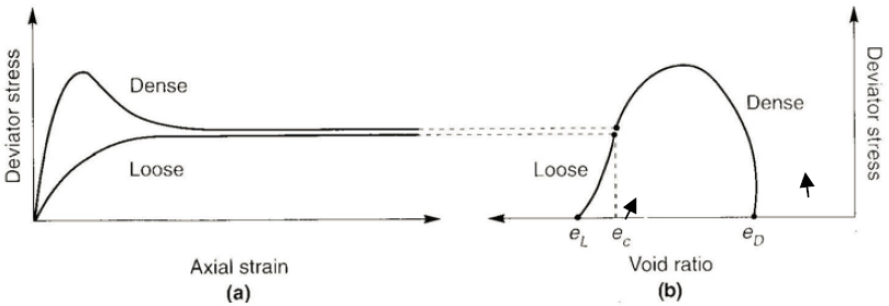
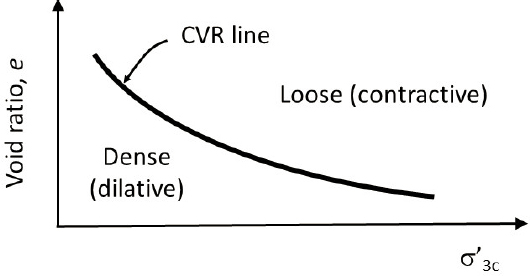
When monotonically sheared, initially loose and dense dry sands deform in fundamentally different manners with respect to their stress-strain and volume change (drained) behavior. Figure 2.1 illustrates the stress-strain and volume change behavior (change in void ratio) of a dry soil in loose and dense states confined under the same effective stress. The loose soil can be seen to contract (decreasing void ratio) and the dense soil to dilate (increasing void ratio) with increasing shear strain. Note that at large shear strain, neither loose nor dense soil continues to change in volume (as shown in Figure 2.1b). At large strains both loose and dry soil reach the same constant void ratio, termed the critical void ratio (ec). The critical void ratio is related uniquely to the effective confining pressure via the critical void ratio (CVR) line (often called the critical state line or steady-state line), as shown in Figure 2.2. The CVR line marks the boundary between loose and dense states; that is, between where the soil demonstrates contractive and dilative responses under monotonic shear loading. All soils tend to move toward the CVR at large monotonic shear strains.
Loose soil (i.e., soil with a void ratio greater than the CVR) is contractive; its void ratio or effective stress must decrease to reach the CVR line. Dense soil (i.e., soil with a void ratio lower than the CVR) is dilative; its void ratio or effective stress must increase to reach the CVR line.
If loads are applied to a saturated soil when there is not sufficient time for the water to move in or out of voids (e.g., the load is applied rapidly or the soil has a low permeability), the loading is said to be undrained. Since the water in a saturated soil is nearly incompressible, the tendency for volume change will cause changes in porewater pressure and effective stress. In loose soils, the tendency for contraction leads to increased porewater pressure and reduced effective stress. In dense soils, the tendency for dilation leads to reduced porewater pressure and increased effective stress.
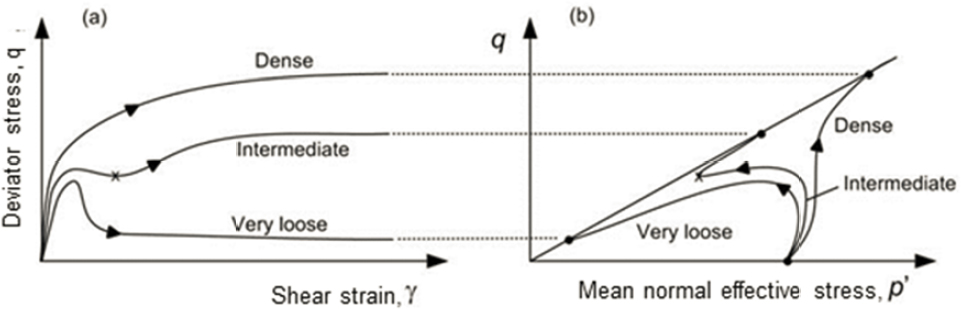
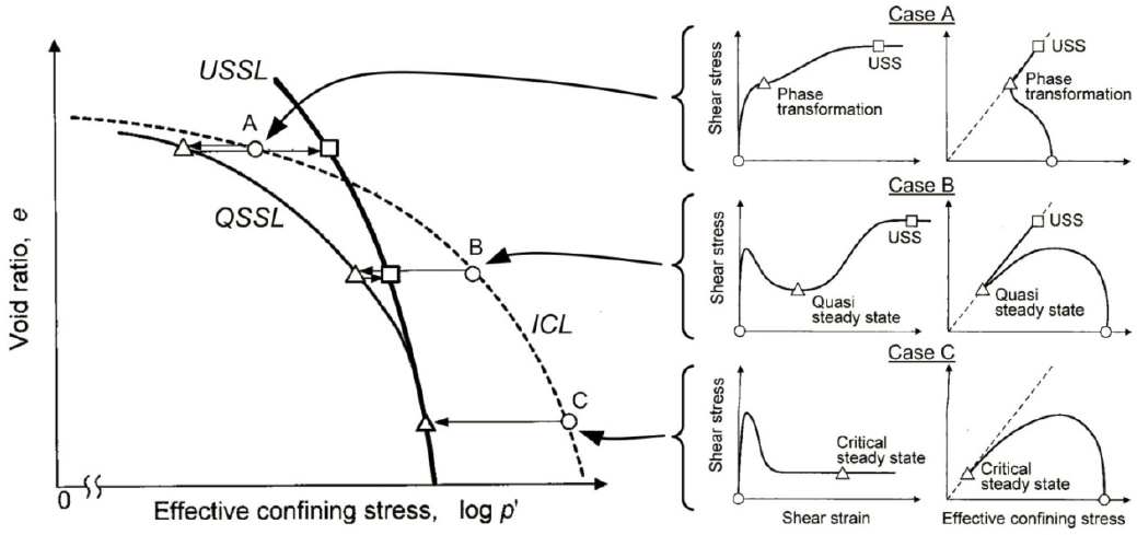
Saturated soils with initial states that plot well above the CVR line are highly contractive and, after reaching a peak shearing resistance at low strains, will generate high pore pressures with concurrent large reductions in effective stress. Such soils can often shear to large strains with low shearing resistance. Dense soils with initial states that plot well below the CVR line will be dilative with decreasing porewater pressures and increasing effective stress; these soils mobilize high shearing resistance at large strains when saturated due to decreasing pore pressure and concurrent increase in effective stress. Soils of intermediate density (i.e., having density between what is considered loose and dense) exhibit initially contractive behavior and mobilize a peak shearing resistance at low strains followed by a reduction in shearing resistance. After mobilizing the peak shearing resistance, however, these soils will dilate until a constant shearing resistance is reached. These three conditions are illustrated in Figure 2.3 and are discussed in more detail by Castro (1969).
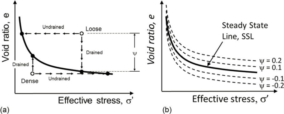
A steady state of deformation, in which a soil shears with constant volume, constant effective stress, constant shearing resistance, and constant strain rate, has been postulated to be a unique function of void ratio and effective stress for a given soil (Castro and Poulos, 1977; Poulos, 1981). Steady-state deformation can be represented graphically on a plot of void ratio versus effective stress as a steady state line (SSL). To simplify the explanation, the SSL can be considered nearly equivalent to the critical state CVR line. The degree to which a soil contracts or densifies, therefore, depends on its state (i.e., its density and effective stress conditions) relative to the SSL. The state parameter (ψ) is a measure of how far the initial state of a soil plots above (or below) the SSL and can be represented mathematically as
ψ = e – ess
where e is void ratio and ess is the void ratio under steady-state conditions. The value of ψ reflects the influence of both mass density and effective stress on soil behavior, and it is an index of a soil’s tendency to change volume. This tendency for volume change is, in turn, related to the tendency for pore pressure and strength to change in a saturated soil when sheared. Soils with positive state parameters plot above the SSL (see Figure 2.4b) and exhibit levels of contractiveness (i.e., the tendency for pore-pressure increase and strength loss when saturated) that increase with increasing state parameter value. Soils with negative state parameters plot below the SSL and tend to be dilative (i.e., have a tendency for pore-pressure decrease and strength gain when saturated) upon monotonic shearing. Under cyclic loading, soils with both positive and negative state parameters will tend to generate increasing pore pressure and can liquefy under sufficiently strong loading.
The transition from contractive to dilative behavior observed in soils of intermediate density occurs at the phase transformation point (Ishihara et al., 1975); that is, the point at which the soil
transitions from contractive to dilative behavior. The phase transition point represents a point of minimum local shearing resistance. Undrained loading beyond the phase transformation point produces dilation, a decrease in pore pressure, a higher effective confining pressure, and, consequently, higher strength at large strains. The point at which a local minimum shearing resistance is observed at moderate strain levels has been called the quasi-steady state of deformation (Alarcon-Guzman et al., 1988). The shearing resistance at very large strain (i.e., at the point where the shearing resistance no longer changes) is referred to as the ultimate steady state (USS) strength (Yoshimine and Ishihara, 1998) to distinguish it from the quasi-steady state strength.
As the void ratio of a soil decreases with increasing effective stress, the relationship between the quasi-steady state line (QSSL) and ultimate steady state line (USSL) of a soil changes with effective stress. Figure 2.5 illustrates the relationship between the quasi-steady state and ultimate steady state at different initial effective stress levels (Yoshimine and Ishihara, 1998). The figure also illustrates the relationship of the isotropic consolidation line (ICL), the line describing the relationship between void ratio and the effective confining pressure for one particular soil prior to shearing the specimen. Because the ICL is typically flatter than the USSL, the state parameter increases, and the soil becomes more contractive and potentially more liquefiable, as the effective confining pressure increases.
Behavior Under Cyclic Shear Stress Reversal
Earthquake loading may be characterized by repeated shear stresses of fluctuating intensity, with the added characteristic that the direction of the applied shear stress reverses. Shear stress reversal is an important characteristic of the earthquake loading, as both loose and dense soils tend to contract at small induced shear strains and therefore generate positive excess porewater pressures when subject to shear stress reversal (Martin et al., 1975). In steep slopes subjected to weak shaking, the combination of high static shear stress and low cyclic shear stress can keep the shear stress from reversing direction under undrained conditions, thereby preventing liquefaction triggering. Cyclic shear stresses may also exceed the shear capacity of soils in sloping ground and trigger a flow slide if the soil is loose of the critical state or contractive.
The stress-strain and pore-pressure generation behavior of sands subject to cyclic loading have been investigated through laboratory tests. The stress-strain and stress path behaviors of a clean sand1 subjected to undrained cyclic simple shear loading are described in Box 2.2. With repeated stress reversal loading cycles, all liquefiable soils exhibit increases in excess pore pressure (i.e., porewater pressure in excess of the initial steady-state pressure) and associated effective vertical stress decreases. In liquefaction analyses, the excess pore pressure is often expressed as a pore pressure ratio (ru)—defined as the ratio of the excess pore pressure to the initial vertical effective stress. The pore-pressure ratio is an index of how close a soil is to liquefaction. Prior to cyclic loading, ru = 0.0. As excess porewater pressure is generated, and thus ru increases, the soil softens and the cyclic shear strain amplitude increases. The rate at which softening and strain levels increase accelerates as liquefaction is approached. In some cases (e.g., for sites with no initial static shear stress on the horizontal plane and for loose soil sites where cyclic loading induces stress reversal) ru can approach and may actually reach 1.0 (at which point the effective stress is zero). For sites without an initial static shear stress on the horizontal plane, ru approaches and may actually be equal to 1.0 at liquefaction. For sites with an initial static shear stress on the horizontal plane not subject to stress reversal, flow may occur (or initiate) at values of ru less than 1.0. The softening and deformation produced by flow are driven by the static shear stresses.
___________________
1 According to accepted engineering standards (ASTM, 2011), “clean” sands refer to those with less than 5% fines content (i.e., grains smaller than 0.075 mm).
Effect of Initial Effective Stress
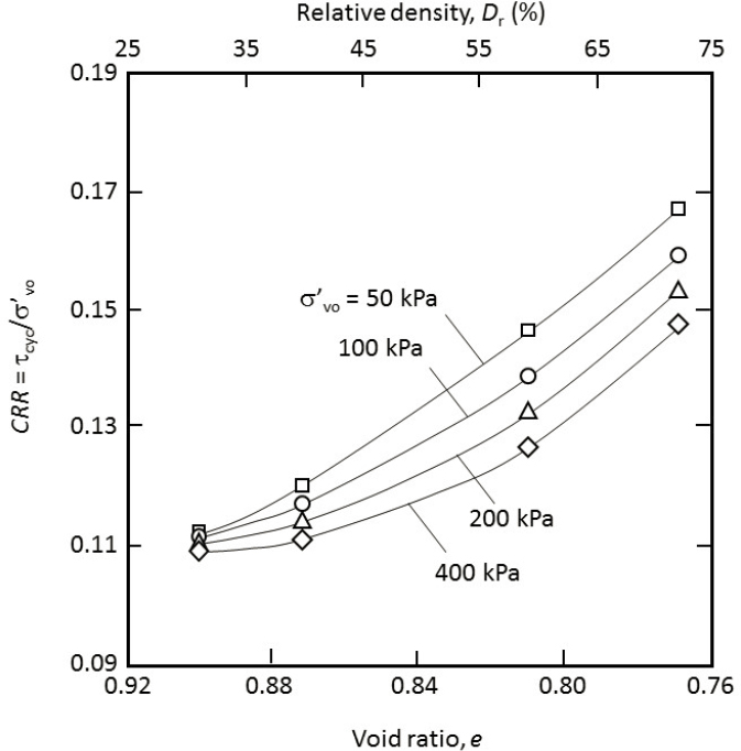
At a given density, steady-state and state parameter concepts predict that contractiveness increases with increasing effective stress. Increased effective stress in the field is usually accompanied by increased density (i.e., smaller void ratio), however, which tends to reduce contractiveness. The cumulative effect of increased effective stress on contractiveness, therefore, depends on whether the steady state line is steeper or flatter than the consolidation curve. Typically, as shown in Figure 2.5, the steady state line is somewhat steeper than is the consolidation curve. As a result, the cyclic stress ratio required to cause liquefaction decreases with increasing initial effective confining pressure. Figure 2.6 presents the results of cyclic simple shear laboratory tests performed without an initial static shear stress on the horizontal plane on soils of the same density but different effective confining pressures (Vaid and Sivathayalan, 1996). The CSR values in Figure 2.6 are all for the same number of cycles to liquefaction. These curves illustrate the decrease in the cyclic shear stress ratio required to trigger liquefaction in a given number of cycles with increasing vertical effective stress (i.e., increasing depth in the ground).
Liquefaction Susceptibility
Liquefaction susceptibility refers to the potential for liquefaction to be triggered in a soil. Not all soils are susceptible to liquefaction, and the degree of susceptibility may depend on the soil grain size and plasticity.2 The level of earthquake shaking and the in situ state of the soil (e.g., density, soil fabric) at the time of shaking determine whether a susceptible soil will liquefy in a particular earthquake. Factors that influence liquefaction susceptibility are reviewed briefly and qualitatively herein. Determining susceptibility to liquefaction is discussed more comprehensively in Chapter 4.
___________________
2 The plasticity of soil is the ability of a unit of soil to undergo permanent deformation under stress without cracking. Plasticity is also an index of how changing the water content in a soil changes its behavior. Clayey soils, generally considered more plastic than silty or sandy soils, can be deformed without cracking over a wide range of water content. Tests to quantify plasticity have been standardized (ASTM, 2010). The level of plasticity is defined using a plasticity index.
Liquefaction-susceptible soils generally are found within a narrow range of geologic environments and soil age (Youd, 1991). Fluvial (i.e., river transported), colluvial (i.e., gravity transported, such as at the base of a cliff), aeolian (i.e., wind transported), and other processes that sort and deposit soils by grain size can result in the deposition of loose soils susceptible to liquefaction. Liquefaction has occurred in alluvial-fan, beach, estuarine, and other deposits. Many constructed earth fills (i.e., man-made soil deposits) are susceptible to liquefaction, including, in particular, deposits created by hydraulic filling, which can replicate river and stream processes.
Primary compositional factors that influence the liquefaction susceptibility of soils include grain size and, for the finer-grained fraction, the plasticity. Grain size and plasticity are used to identify soils not considered to be liquefiable (e.g., those that are fine grained and of medium to high plasticity). Criteria for establishing whether or not a fine-grained soil is susceptible to liquefaction are also addressed in Chapter 4.
FACTORS AFFECTING LIQUEFACTION POTENTIAL AND ITS CONSEQUENCES
A number of factors affect the potential for initiation of liquefaction. The next sections include discussions on the effects of load amplitude, soil type, initial shear stress, shear strain amplitude, age, and hydraulic conditions.
Effect of Load Amplitude, Duration, and Density
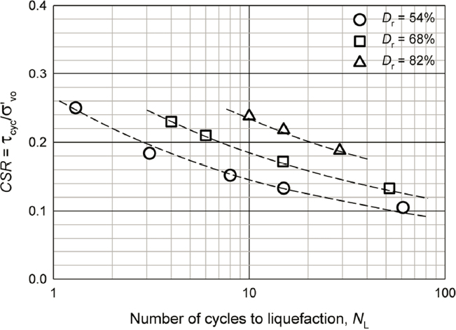
The excess pore pressure generated in a monotonic loading test on loose, saturated sand increases with increasing shear stress, so the excess pore pressures under cyclic loading should be expected to increase at a faster rate as the amplitude of the cyclic loading increases. An increase in the duration of strong shaking should also be expected to increase excess pore-pressure generation and the potential for triggering liquefaction. Figure 2.7 shows the relationship between the number of uniform stress cycles required to induce liquefaction for a soil at three different initial relative densities. The cyclic shear stress required to trigger liquefaction (i.e., the CSR defined in Box 2.1), the number of cycles required to trigger liquefaction, or both, for a given CSR can both be seen to increase with increasing density.
Effect of Soil Type on Soil Behavior Under Cyclic Loads
The potential for a soil to liquefy during undrained cyclic loading is influenced by the extent to which the soil skeleton tends to contract under such conditions. Loose, granular, and nonplastic soils such as sands, gravels, and nonplastic silts can have high levels of contractiveness. Therefore,
porewater pressures within them can build, the soil softens and the cyclic shear strain amplitude increases, and liquefaction will be triggered. Plastic fine-grained soils may exhibit some softening under cyclic loads, but their tendency to contract is less, and excess pore pressure may stabilize at values such that the effective stress does not approach zero (and the soil does not liquefy).
Effect of Initial Shear Stress
No shear stress exists on horizontal planes at level-ground free-field sites (e.g., zero slope) prior to earthquake shaking. In sloping ground, however, at level sites near slopes (e.g., riverbanks and embankment toes), and at level sites on which structural loads are imposed, there will be an initial shear stress on the horizontal plane prior to earthquake shaking. That initial horizontal shear stress can affect the rate of pore-pressure generation. Experimental studies (Seed and Harder, 1990; Boulanger, 2003b) have shown that pore pressures are generated more quickly in highly contractive (e.g., very loose) soils in the presence of an initial horizontal shear stress than when no initial horizontal shear stress is present. In less contractive or dilative soils (e.g., medium dense to dense), however, the presence of an initial horizontal shear stress tends to suppress pore-pressure generation. Laboratory studies have shown that the three-dimensional stress state and the shear strain level can also affect pore-pressure development (Boulanger, 1990; Kammerer, 2002; Cetin and Bilge, 2015).
Effect of Shear Strain Amplitude
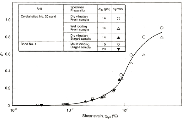
Different specimen preparation procedures produce soil specimens with different fabrics, and differences in stress-based measures of cyclic shearing resistance observed in tests on specimens reconstituted using different procedures (Ladd, 1974; Mulilus et al., 1977) led investigators to explore the use of cyclic strain amplitude as a measure of loading, or demand, for liquefaction. Data compiled by Dobry and Ladd (1980) suggest that the relationship between pore pressure and cyclic shear strain is relatively insensitive to initial variations in the soil fabric. That finding is consistent with the finding of Silver and Seed (1971): shear-induced volume change is more closely related to cyclic shear strains than to cyclic shear stresses. Figure 2.8 shows the relationship between pore-pressure ratios and shear strain amplitude developed by Dobry and Ladd (1980) from testing of reconstituted specimens of two soils, one of which was prepared using three different specimen preparation methods (see Chapter 5).
Effect of Age
Empirical observations (e.g., Youd and Hoose, 1977; Youd and Perkins, 1978) indicate that earthquake-induced liquefaction is more common in younger (e.g., Holocene age) soil deposits than in older (e.g., Pleistocene age and older) soil deposits. Experimental investigation of age effects is complicated by the difficulty simulating changes on geologic timescales, but combinations of experimental and field data have shown that older soils are generally more resistant to pore-pressure generation than younger soils are (Seed, 1979; Troncoso et al., 1988; Arango et al., 2000; Robertson et al., 2000). Mechanisms of aging effects are not understood
completely, but they may involve particle and particle group reorientation, increases in in situ lateral stresses, grain interlocking, chemical precipitation (cementation), and internal stress arching (Mitchell and Solymar, 1984; Mitchell, 1986, 2008; Schmertmann, 1991) operating on different timescales. It should be noted that aging effects can be “erased” when a soil’s structure or fabric is disturbed or destroyed by events. Thus, the “age” of a soil deposit from a liquefaction standpoint can be reset to zero by the triggering of liquefaction, even if large strains do not develop (Andrus et al., 2009; Hayati and Andrus, 2009; Maurer et al., 2014a). The influence of soil age on liquefaction potential is discussed in more detail in Chapters 3 and 4.
Hydraulic Considerations
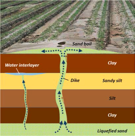
Redistribution and dissipation of excess porewater pressure can strongly influence the behavior of a soil as it approaches and undergoes liquefaction. Excess porewater pressure generally develops in a spatially variable manner, producing hydraulic gradients that cause water to flow from locations of high hydraulic head (i.e., locations of high excess porewater pressure) toward locations of low hydraulic head (locations of lower excess porewater pressures).3 Water from areas of high excess porewater pressure will often flow toward the ground surface. Sand boils, the most common surficial evidence of liquefaction, may form when water and entrained soil particles are ejected at the ground surface from a shallow liquefied soil layer (see Figure 2.9).
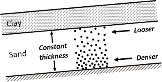
Excess porewater pressure migration and dissipation can be impeded if a low-permeability soil layer lies above a liquefiable soil layer. In such cases, upward flowing porewater can build up
___________________
3 The presence of an ambient artesian groundwater pressure could increase the rates and extents at which excess porewater pressures develop, redistribute, and dissipate. A correlation between such pressure to liquefaction hazards has been made between artesian pressures and liquefaction during the 2010 M 7.1 earthquake in New Zealand (e.g., Cox et al., 2012), although other researchers are less certain about the contributions (e.g., Tayler et al., 2012).
below the base of the low-permeability layer, and the density of the soil just below the low-permeability layer can become very low, as illustrated in Figure 2.10. In extreme cases, a water interlayer may form at the base of the low-permeability layer. Because porewater migration may continue after the ground has stopped shaking, the most critical condition with respect to the stability of a liquefied soil profile may exist after shaking ends.
EARTHQUAKE LOADING
Liquefaction is triggered when the loading applied to a liquefaction-susceptible soil exceeds the liquefaction resistance of the soil. Therefore, the evaluation of liquefaction triggering requires establishing consistent measures of earthquake loading and liquefaction resistance. Early investigations of liquefaction resistance were based on laboratory testing to develop cyclic strength
curves like those shown in Figure 2.7. Earthquake loading was, and still is, based on representative values of the amplitude of the uniform cyclic shear stress and the number of uniform loading cycles for the design earthquake. This approach requires development of procedures to establish a representative earthquake-induced shear stress and the number of uniform loading cycles as a function of earthquake magnitude, as discussed in the next section.
Ground Motion Intensity Measure
For most liquefaction analyses, the intensity of the design ground motion is characterized by the peak cyclic shear stress and an earthquake magnitude. The peak cyclic shear stress, in turn, depends on the design peak ground acceleration (PGA). As noted in Box 1.3, 65% of the peak cyclic shear stress ratio is typically used as the value of the equivalent uniform cyclic load. This reduced value of the peak cyclic shear stress was introduced to characterize the earthquake loading to account for the fact that the peak cyclic shear stress occurs only once during the earthquake and that all of the other load cycles during the earthquake are of lower amplitude. With subsequently introduced magnitude scaling factors (MSFs) that account for durational effects of the earthquake shaking, however, the use of the reduced (i.e., 65%) peak cyclic shear stress ratio is no longer needed; nevertheless, it has been retained for historical purposes (i.e., use of a different percentage reduction in peak cyclic shear stress ratio will result in either a shift in the triggering correlation or a commensurate offset in the MSFs such that the cyclic stress ratio adjusted to an M 7.5 will remain unchanged).
Sources of the Design Intensity Measure
The earthquake intensity measure used in design (e.g., the peak ground acceleration) is typically established based on a ground motion hazard analysis that considers the potential for strong ground shaking at the site from recognized earthquake sources. Seismic hazard analyses can be performed deterministically or probabilistically. Deterministic analyses consider a particular scenario event, often taken as the largest assessed magnitude earthquake occurring at the shortest source-to-site distance. Probabilistic analyses account for the distributions of magnitude, source-to-site distance, and levels of ground shaking, and they compute the probabilities of exceeding different ground shaking levels based on the probabilities of all combinations of magnitude, distance, and ground shaking level. Project-specific hazard analyses may be performed for certain projects, such as for critical infrastructure or in situations where lives may be at risk. Alternatively, published results of seismic hazard analyses from a recognized authoritative source (e.g., from the U.S. Geological Survey National Seismic Hazard Mapping Program)4 may be used. The selection of an appropriate earthquake magnitude for use with a probabilistic design acceleration is discussed in Chapter 4.
___________________
4 See, for example, http://geohazards.usgs.gov/deaggint/2008/documentation.php.
SOIL RESISTANCE TO LIQUEFACTION
The evaluation of liquefaction resistance has evolved in the last 40 years from laboratory-based methodologies to a field-based framework, largely because obtaining high-quality samples from the field for laboratory testing is difficult. The field-based framework characterizes liquefaction resistance using a “representative” in situ test parameter from a test such as the standard penetration test (SPT; described in Box 2.3), the cone penetration test (CPT; described in Box 2.4), and shear wave velocity (Vs) testing (described in Box 2.5). Methods for evaluating soil resistance to liquefaction are discussed in detail in Chapter 4.
CONSEQUENCES OF LIQUEFACTION
The triggering of liquefaction can lead to various consequences to soil and site properties as well as to physical damage, economic loss, and potential loss of life. Some factors that influence the main consequences of liquefaction are described below. Descriptions of liquefaction consequences and procedures for predicting those consequences are presented in Chapters 6 and 7.
Alteration of Ground Motion
The response of buildings, bridges, pipelines, and other elements of infrastructure underlain by liquefiable soils will be strongly influenced by how liquefaction affects the characteristics of the ground surface motions. Ground motion frequency change often occurs suddenly when liquefaction is triggered as a result of the rapid reduction in shear stiffness at high pore-pressure ratios. The frequency content change can be so abrupt and obvious that it is easily noticed in ground surface accelerograms.
While the onset of liquefaction typically reduces the intensity of the ground surface acceleration (as compared to ground surface acceleration had the site not liquefied), the lower-frequency components of the ground motion may increase subsequent to liquefaction triggering. Even relatively low accelerations at low frequencies can produce very large, long-period displacements following triggering—sometimes referred to as ground oscillations. Cases of damaging ground oscillation have been reported in a number of earthquakes (Youd and Keefer, 1994; Youd, 2003; Holzer and Youd, 2007).
Lateral Spreading and Flow Sliding
Initial shear stresses under sloping ground conditions can drive permanent lateral deformations of the ground subsequent to liquefaction. These lateral deformations are referred to in practice as lateral spreading and flow sliding. When initial shear stresses are less than the residual strength of the soil (i.e., the shearing resistance of the liquefied soil at large strain), but the seismically induced stresses exceed the residual strength, lateral displacement builds up incrementally during the earthquake and ceases when the cyclic loading stops and results in lateral spreading. When initial static shear stresses are greater than the available strength of the liquefied soil (e.g., in ground with a greater slope or lower soil density), lateral deformation will not only build up during the earthquake but also continue to accumulate after the shaking stops. This mechanism is referred to as a flow slide. While lateral spreading deformations may be limited enough to be accommodated in engineering design, displacements caused by flow sliding typically cannot be accommodated in design and must be addressed through mitigation measures. Both lateral spreading and flow sliding are often accompanied by cracking of the ground, separation between the ground and embedded structures, ejection of soil and water from the ground cracks, and surficial settlement (e.g., formation of a graben) due to the lateral movement. When the level of lateral spreading is small, these effects may be subtle and hard to detect.
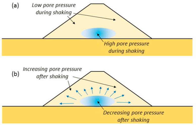
When earthquake shaking generates nonuniform excess pore pressures, hydraulic gradients may develop that can, in turn, cause increased excess porewater pressures in other areas. This would then result in a decrease in the effective stress and strength. This strength decrease can be important for stability after the shaking has stopped. Figure 2.11 illustrates this phenomenon for an embankment, but it can also occur beneath natural and man-made slopes. Slope failures associated with this type of pore pressure redistribution have occurred from minutes to hours after strong earthquake ground shaking (Seed et al., 1973; Ishihara, 1984). When porewater flow is
impeded by low-permeability soils, effective stresses can become extremely low and void ratios can become extremely high. Such void redistribution effects can, in extreme cases, lead to the development of water interlayers beneath the low-permeability zones.
Liquefaction-Induced Settlement
Volume loss due to the dissipation of excess pore pressure in the liquefied soil during and after an earthquake generally results in ground surface settlement. Settlement can cause damage to structures if the settlement is not uniform beneath the structure. Settlement can also leave a gap beneath the pile-supported structures, cause distress to utilities buried in the soil, and alter drainage grades at a site. The total volumetric strain (volume loss) following liquefaction is not explained entirely by pore-pressure dissipation and the reconsolidation of the soil. This is because cyclic loading of the soil beyond the liquefaction triggering changes the soil structure such that the soil is more compressible than it was in its original state. Procedures for predicting volumetric strain in saturated sands are discussed in Chapter 7. The settlement of structures underlain by liquefiable soil is also affected by local interaction between the structure and the soil, and it can differ significantly from the “free-field” settlement (Unutmaz and Cetin, 2012; Bray and Dashti, 2014; Bray et al., 2014). Settlement of the ground surface can also be associated with lateral soil movement and with the extrusion of soil (ejecta) from beneath the ground surface.
Damage to Foundations
Liquefaction-induced damage to structures supported on shallow foundations is typically caused by differential vertical and horizontal displacements. This is particularly true for structures supported on isolated spread footings or lightly reinforced mats, as is often the case for residential and light commercial structures (Cubrinovski et al., 2011; Bray et al., 2014). Structures supported on stiffer mat foundations may also be subject to distortion, settlement, and tilting when underlain by liquefiable soils. Embedded structures supported on mats or shallow foundations may also be subject to damaging lateral loads and displacements associated with lateral spreading and flow sliding.
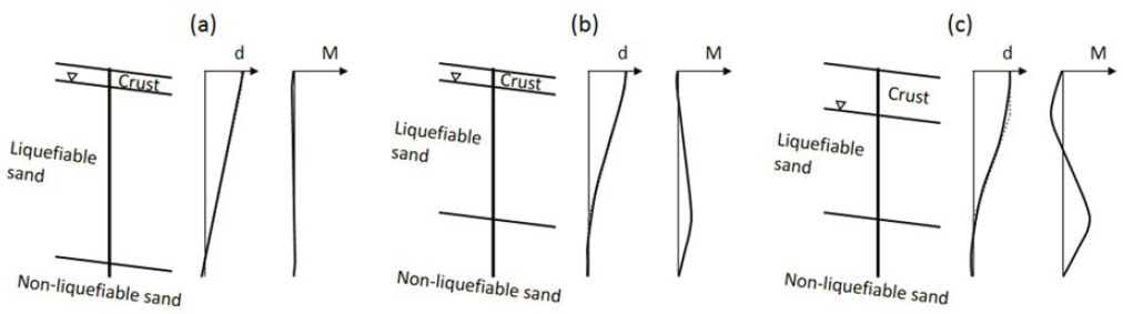
Liquefaction-induced damage to deep foundations is associated typically with lateral spreading and flow sliding. Lateral movement of the ground can induce lateral loads on pile caps and bending moments and shear forces in the deep foundation elements. The magnitude of these loads depends on the stiffness of the structure-foundation system and restraint provided by non-liquefiable soils above and below the liquefied zone (see Figure 2.12). Settlement of liquefied soil during and following an earthquake can lead to negative skin friction (i.e., downdrag loads) on pile foundations as discussed in Chapter 7, although reports of damage to deep foundations due to downdrag from the settlement of liquefied soil are rare.
Damage to Retaining Structures
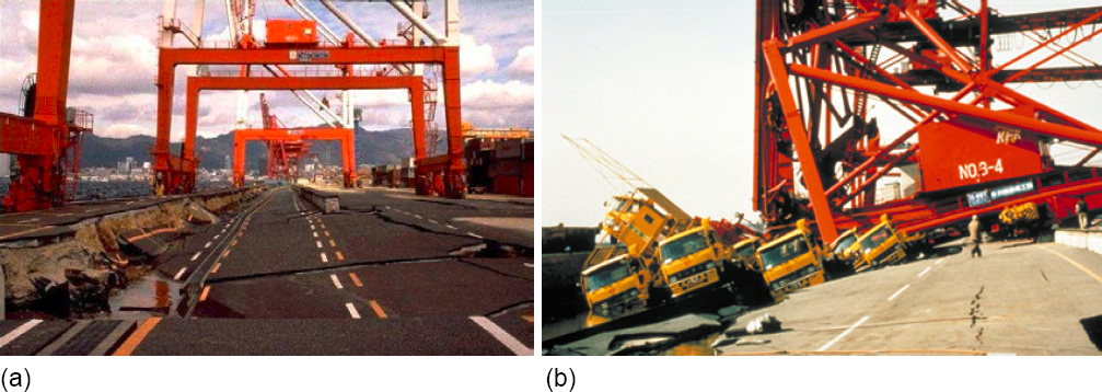
Bulging or tilting of retaining walls, sliding of the wall, and damage to structures on or behind the wall may result if liquefaction-induced increases in earth pressure and decreases in lateral resistance are not anticipated in design. In the 1995 Hyogo-ken Nanbu (Kobe, Japan) earthquake, many gravity quay wall structures at the Port of Kobe settled, tilted, and slid laterally due to a combination of increased lateral pressure, reduced lateral resistance, and bearing capacity failure beneath the wall structures (see Figure 2.13). These deformations destroyed gantry cranes that ran on rails along the tops of the walls and made the berths unserviceable, resulting in significant economic loss to the port (see Chapter 1).
___________________


