
Topic 3:
System Effects and Testing
The third workshop topic focused on system effects and testing and featured presentations by Mike Peretti of General Electric, Olivier L. de Weck of the Massachusetts Institute of Technology, Jorge Ledo of the National Center for Advanced Manufacturing (NCAM), Louisiana College of Engineering, and Michel Barsoum of Drexel University. The speakers gave separate presentations and took questions during and after their individual presentations.
DESIGN OPTIMIZATION INVOLVING MANUFACTURING PROCESS CONSTRAINTS
Mike Peretti, General Electric
Mike Peretti briefly outlined the history of technical innovation in jet engine design. The technology progressed from the early U.S. jet engines to the first U.S. turboprop engine to high-bypass engines by the late 1960s. Later developments included the first composite fan blade in airline service, the 120,000+ thrust engine, modular power tile, and, most recently, ceramic matrix composite production components.
He said that since approximately 2004 there have been a number of new material and process introductions for jet engine manufacturing, including the following:
- Titanium-aluminum turbine blades,
- Advanced high temperature SX (Single Crystal1) turbine blade alloy,
- R130 high temperature powder turbine disk alloy,
- SiC/SiC CMC turbine shrouds,
- High-performance CoCr turbine fuel nozzle produced using additive manufacturing,
- Polymer composite flowpath spacer designed to rotating part standards,
- Carbon/epoxy composite fan case,
- Advanced tribological coatings for compressor airfoils,
- GE1014 ultra-high torsional strength steel shaft,
- NiAl turbine blade coating,
- Translational friction welding of titanium and Ni disks,
- Low Re content SX turbine blade alloy family, and
- R65 cast and wrought turbine disk and case.
Peretti said that the introduction of new materials can take many years. For instance, modifying an existing material for a noncritical component can take approximately 2 to 3 years, but modifying an existing material for a critical structural component can take 4 to 6 years. Developing a new material within a system that we already have experience with can take approximately 10 to 12 years. Peretti said that introducing a new material class and/or process can take up to 20 years and even longer. This requires both developing design practices that fully exploit the performance of the material and establishing a viable industrial base.
According to Peretti, a material often can be a solution looking for a problem. He argued that a good rule is that a new material should target a specific platform or part. But sometimes timing is an issue. For example, he said that if a material is not ready enough but there is a deadline to develop a product, the product could be produced and there may be a wait of many years to introduce that material at the next opportunity.
Peretti noted that material properties are the first consideration and producibility is a close second. In order to be useful, materials need to be manufacturable at required cost and quality, and the manufacturers need to be able to establish material and process specifications. Scaling up, Peretti explained, may also present problems. For instance, engineering properties may not follow from the small scale to the large scales required for production. It could be, he said, because of thermal properties or some other factor; chemical changes can drive variations in properties and the use of predictive models can reduce development time and cost and predict stability.
___________________
1Single crystal refers to a component produced in such a way that it has no grain boundaries present and is therefore composed of only a single grain.
Peretti explained that the manufacturing process determines the properties. The production process requires good knowledge of allowable material property ranges. The process also needs to be stable in order for properties within the ranges to be obtained.
Peretti then turned to the role of additive manufacturing in jet engine production. He said that this changes the design process. “If I can think it, I can make it,” he said. But he said that the most difficult thing is getting designers to think in a different way that enables them to take full advantage of the new technology. Simply replicating existing parts is not the right way to do things.
Peretti provided an example of an object that consisted of 20 parts. A design team using additive manufacturing technology initially started designing all 20 parts to be manufactured individually, but then determined that they should simply make one single part, taking advantage of the technology’s capabilities. Another example he provided was a bracket. Using additive manufacturing, a group was able to redesign it with an 80 percent weight reduction via topological optimization. He said that additive manufacturing can be the key to an accelerated development and implementation program, but people definitely have to learn how to exploit the technology to the fullest extent.
Peretti warned about the possibility of design resulting in “missing the train.” The design and development time for a new commercial turbofan engine is about 10 years and costs about $1 billion. Materials and processes are frozen several years before production. Peretti explained that although a jet engine manufacturer will try to introduce new materials during production, they are limited to what is possible with a frozen design.
In response to a question, Peretti said that General Electric produces about 1,800 to 2,000 engine units per year. This prompted a discussion about analogies for military vehicle production runs, which are typically small. The U.S. Army has thousands of tanks and armored personnel carriers that will be replaced over the next two decades, but it only procures a few hundred vehicles per year. This represents a tiny fraction of the number of commercial vehicles that are produced each year. Finding a way to adopt commercial production techniques may be useful, but will not be easy, a participant noted. One participant suggested that the best analogy would be locomotives.
SWITZERLAND’S F/A-18 PROGRAM AND MATERIALS SUBSTITUTION
Olivier L. de Weck, Massachusetts Institute of Technology
Olivier L. de Weck spoke about a unique aircraft redesign challenge and the issues affecting vehicle development and how these examples could be used to develop management models for advanced development.2
De Weck discussed the experience that Switzerland has had with its F/A-18 Hornet fighters. The U.S. Navy introduced the F/A-18C and D versions in 1987. Switzerland purchased 26C models and 8D models in the mid-1990s, with deliveries starting in 1996. But the Navy and the Swiss air force used their respective aircraft in different ways. The Navy used its aircraft in a fighter-and-attack role, de Weck said, accumulating about 3,000 hours per aircraft. The average minimum sortie was about 90 minutes, with a maximum g-loading on the aircraft of 7.5 positive g’s. But the Swiss used their existing aircraft in an interceptor role, accumulating 5,000 flight hours per aircraft. De Weck then went on to say that they flew them for an average minimum sortie of about 40 minutes, with a maximum 9.0 positive g-loading. The Swiss, therefore, determined that, because they were going to use their F/A-18 Hornets in a different manner, the aircraft would have to be redesigned to operate in these conditions.
He also stated that the Swiss then redesigned their F/A-18s before production. The Swiss first specified a new mission usage spectrum for the Swiss aircraft, which was then applied to the existing U.S. Navy aircraft configuration. The engineers had to then identify and prioritize “hot spots” that were most in need of change. The engineers then conducted their redesign and implemented the local changes at the hot spots.
The biggest change involved the aircraft’s center fuselage structure, de Weck explained. The engineers substituted materials, strengthened the structure, and included heat treatment for some areas of the aircraft. In several locations, the engineers had to substitute titanium for aluminum to extend the fatigue life.
The wing carry-through bulkheads had to be modified along with the center barrel section of the aircraft. During the course of the upgrade, the Swiss discovered that changes propagated throughout the entire aircraft system. For example, the new material and additional strengthening shifted the aircraft’s center of gravity, which also required a change in the flight control software. In addition, the fuselage had to be stiffened, which had the additional effect of increasing the gross takeoff weight.
___________________
2 See also Olivier L. de Weck, “A Systems Approach to Mass Budget Management,” 11th AIAA/ISS-MO Multidisciplinary Analysis and Optimization Conference, 6-8 September 2006, AIAA 2006-7055.
De Weck indicated that the changes increased the cost per aircraft by approximately $10 million. The changes also produced some unexpected surprises along the way. The Swiss learned that changing a system or a product after its initial design is established can be expensive and time-consuming if the change was not anticipated in the original design. Some changes were local and remained local, but other changes started local and then propagated through the system in complex and unanticipated ways.
De Weck discussed the importance of mass budget management. He said that mass management during vehicle design is critical to maintaining performance targets. In ground vehicles, this affects range and transport. Some systems are critically dependent on delivering functional performance at minimal mass, such as aerospace vehicles, ground vehicles, watercraft, and mobile electronic products. He said that this is not as important an issue for industrial equipment and civil infrastructure, but it can be radically different for aircraft. As an example, de Weck showed how final dry mass of an aircraft can impact performance. For example, in the Boeing 737 commercial passenger jet, reducing the aircraft mass by 20 percent results in a substantial increase in the aircraft’s range.
De Weck then turned to the subject of automobiles and issues affecting their mass. Automobile mass definitions are defined by regulatory limits. These are set on the “curb weight” in kilograms or pounds. Curb weight is the total weight of an automobile with standard equipment, oil, lubricants, coolant, and a full tank of fuel that is not loaded with passengers or cargo. The gross weight is the total weight of a vehicle when fully loaded with passengers or cargo. The gross vehicle weight rating is used in vehicle regulations. Typically 6,000 pounds (2,721 kg) is a key weight, and vehicles weighing more than 6,000 pounds are restricted from many city roadways.
De Weck explained a systems framework for mass management. He said that performance requirements drive the mass. The second step is determining appropriate mass margins, followed by allocating mass to subsystems. Following this, he said, mass creep must be managed. The final step in development is trading off light-weighting versus cost.
During the first step, designers conduct parametric modeling of mass, determine the key performance requirements, map how requirements impact system mass, and then create parametric scaling relationships. De Weck said that these can either be first-order, physics-based models or empirical models based on historical data. Accuracy of the models depends on the size and quality of the data set. Increasing the number of parameters can increase model fidelity, but there will always be noise in the data used in the model. He said that this process only provides an estimate of aggregate system mass within approximately 5 percent. It is useful during conceptual design and trade space analysis, but not for detailed design.
In the second step, de Weck said, designers have to manage mass margins. The margins are reserves that are not allocated to subsystems but are controlled by proj-
ect managers. De Weck noted that mass growth is common for vehicle development and can typically range from 10 to 60 percent. He said that typical guidelines are to establish the SRR3 mass plus a 30 percent margin. For preliminary design review, the goal should be to keep 20 percent mass margin, said de Weck. Prior to critical design review, the goal should be to try to keep a 10 percent mass margin. Prior to initial operating capability, the goal should be to try to keep a 5 percent mass margin.
De Weck added that in many vehicle design cases maximum gross (dry) mass is fixed and cannot be exceeded. Thus, it is necessary to establish margins and thresholds and manage throughout the project. Weight reduction “exercises” can drive up both project cost and time.
Finally, de Weck stated that there are some open issues deserving further research, including the following:
- Materials substitution for lightweighting can reduce the structural mass, but will it increase life-cycle cost or decrease survivability?
- How does modularity impact system mass?
- How will modular designs, which are typically heavier than integral designs due to inefficiency and extra interfaces, be utilized?
- What are the impacts of mass savings on life-cycle cost—for example, cumulative aircraft fuel consumption savings versus upfront manufacturing impact?
- How will mass increases be managed during operations such as upgrades and retrofits?
De Weck concluded by reiterating that mass management is critical for vehicle design. A systems framework needs to integrate the five issues and address these across the whole life cycle. He said that some firms and industries are more advanced at doing this than others. He noted that there are major differences between vehicle designs. For instance, propellant mass fractions vary wildly. A full tank of gas may only represent about 3 percent of the mass of a car, whereas 27,000 kg of fuel in a 60-ton aircraft is 45 percent of its total mass. But for a rocket, up to 90 percent of the total mass is fuel.
___________________
3 SRR is the System Requirements Review, the first stage in a complex product or vehicle development. It is followed by the Preliminary Design Review, the Critical Design Review, and, finally, Initial Operating Capability.
WEIGHT REDUCTION FOR THE SPACE SHUTTLE EXTERNAL TANK
Jorge Ledo, National Center for Advanced Manufacturing (NCAM)
Jorge Ledo spoke about the space shuttle external tank and efforts to reduce the weight of the tank over the lifetime of the program. He said that NCAM is currently involved in NASA’s Space Launch System (SLS), assisting with weight reduction of that launch vehicle.
The NCAM initial agreement, he said, was signed in 1999, and a new agreement was signed in 2012. NCAM partners with the NASA Michoud Assembly Facility. This is a large site in eastern New Orleans with 2.5 million square feet of advanced manufacturing space and interstate and railway access. Michoud has laboratory and testing capabilities that include materials and processing, analytical chemistry, metallurgy labs, structural load testing, and production support.
The NCAM technology focuses on high performance lightweight structures and “production ready” technologies. NCAM uses friction stir welding and automated placement composite materials.
Ledo described a case study concerning the Space Shuttle’s external tank. The external tank provided the structural backbone for the launch vehicle and had to support the 2.9 million pounds of thrust exerted by each of the two solid rocket boosters, as well as the 1.1 million pounds of thrust exerted by the engines in the tail of the Space Shuttle Orbiter.
He said that the tank consisted of three major subcomponents. At the top was the liquid oxygen tank, which held 145,138 gallons of oxidizer at −297°F. Below this was the intertank, which was an unpressurized structure. Below this was the liquid hydrogen tank, which held 309,139 gallons of fuel at −423°F. In addition, the tank had 38 miles of electrical wiring, more than half a mile of pressure vessel welds, and 4,000 pounds of thermal protection materials (spread over 16,750 square feet).
Ledo also mentioned that the Space Shuttle program existed for 38 years and 135 flights. The overall system evolved during this time to improve both performance and producibility. The tank underwent several major design evolutions: the Heavy Weight Tank, which was first developed in 1973 and used until 1983; the Light Weight Tank, which was used from 1983 until 1998; and the Super Light Weight Tank, which was used from 1998 until the retirement of the shuttle program in 2011. The Heavy Weight Tank weighed 76,000 pounds and was flown six times. The Light Weight Tank weighed 66,000 pounds and flew 86 times. The Super Light Weight Tank weighed 58,500 pounds and flew 43 times.
The Heavy Weight Tank, Ledo said, was made from Aluminum (Al) 2219 and manufactured using the gas tungsten arc welding/tungsten inert gas welding technique. Its weight was reduced over the course of its lifetime. The first two Space Shuttle missions flew with tanks painted white, but NASA left further
tanks unpainted, which reduced weight by 580 pounds. In addition, removing and reducing hardware eliminated a further 713 pounds.
He said the Light Weight Tank started development in 1980, even before the first Space Shuttle launch. NASA mandated a 6,000-pound weight reduction to support the Galileo Jupiter spacecraft, then scheduled for a launch in the mid-1980s. The Light Weight Tank’s design was based on data obtained from Heavy Weight Tank flights, modeling refinements, and other developments. It too was made from Al 2219, but it was manufactured using the VPPA4 welding technique. Weight reduction was achieved through resized membranes and removed or reduced hardware. Ultimately, the designers were able to reduce weight by reducing design margins after they had obtained improved test data and analysis.
Ledo mentioned that the Super Light Weight Tank started development in 1993, with a first launch in 1998. NASA had mandated a 7,500-pound reduction to support the space station then in development. Additional data from earlier flights, along with tests and model refinements, contributed to the design. The new tanks were made with Al 2219 and Al 2195, but a major change was the adoption of friction stir welding. Weight reduction was achieved through changing to orthogrid panels and using design optimization. The change to orthogrid panels also required development of a new manufacturing process for machining, forming, and welding the barrel assemblies.
Ledo explained that because this new tank involved many changes to the design, NASA developed a structural verification plan that included early formation of an independent verification team that included industry experts. Each failure mode was verified by independent analysis, flight history, or testing. The guiding philosophy was “Test what you fly and fly what you test.”
The Super Light Weight Tank evolved further to mitigate production issues with fusion welding. Some parts reverted back to Al 2219, and the liquid hydrogen tank was further optimized.
According to Ledo, there were a number of key lessons learned with the development of the Super Light Weight Tank. These included the following:
- Industry experts should be engaged early in the design verification cycle;
- Verification program should be test-based and failure-mode specific;
- Testing to design capabilities is critical to understand margins;
- Tests should be performed incrementally to reduce program risk;
- Protoflight tests can be used when ultimate load tests are not practical;
- Independent analyses can be used to extend test-based data for similarity verification;
___________________
4 Variable Polarity Plasma Arc (VPPA) is a low-cost, reliable welding method used by NASA beginning in the late 1970s.
- All previous test, analysis, and engineering experience data should be leveraged to the fullest; and
- Designs should “evolve” when introducing new materials and manufacturing processes.
Ledo concluded by discussing NCAM’s current work and partnerships. He said it is working on several applications within aerospace markets, including launch vehicle cryogenic tanks and high-temperature composites. It is also interested in adjacent markets that can benefit from technology transfer. These include the automotive industry, where friction stir welding could be applied to dissimilar metals. Other markets include titanium ship structures, heat exchangers for power generation and liquid natural gas cryogenic storage tanks, and combat vehicles, he added.
FROM MAX TO MXENE: FROM 3D TO 2D
Michel Barsoum, Drexel University
Michel Barsoum of Drexel University spoke about a new class of layered machineable ternary carbides and nitrides known as MAX and two-dimensional (2D) transition metal carbides and carbonitrides known as MXenes. They have some of the characteristics of metals as well as ceramics. He said that these materials have existed for several decades, but that there have been some recent developments that are very exciting. The materials are light, stiff, and can go to high temperatures. Barsoum stated that these materials are better electrical conductors than titanium alloys. In addition, they have qualities similar to machineable ceramics and are highly resistant to high-velocity impacts, such as from rifle bullets. He explained that the technology has transitioned from the laboratory setting and is being used in manufacturing and has been sold for various commercial uses, such as heating elements, where researchers have managed to make the materials into a paper form. The technology also has applicability to high-power batteries.
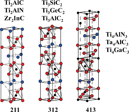
Barsoum explained that the “MAX” phases are layered, hexagonal carbides and that nitrides have the general formula Mn+1AXn, (MAX), where n = 1 to 3, M is an early transition metal, A is an A-group (mostly IIIA and IVA, or groups 13 and 14) element, and X is either carbon and/or nitrogen (see Figure 5). These carbides and nitrides possess unusual, and sometimes unique, chemical, physical, electrical, and mechanical properties that combine the best attributes of metals and ceramics,5
___________________
5 Barsoum, M.W., 2000, The Mn+1AXn phases: A new class of solids; thermodynamically stable nanolaminates. Prog. Solid State Chem 28:201-281; Barsoum, M.W., 2006, Physical properties of the MAX phases in Encyclopedia of Materials Science and Technology, edited by K. H. J. Buschow et al., Elsevier, Amsterdam.
such as high-temperature wear, corrosion resistance, and toughness. They are useful in technologies involving high-efficiency engines, damage-tolerant thermal systems, increasing fatigue resistance, and retention of rigidity at high temperatures.6
Barsoum indicated that, as synthesized, MXenes prepared via hydrofluoric acid (HF) etching have an accordion-like morphology, which can be referred to as a multilayer MXene (ML-MXene), or a few-layer MXene (FL-MXene) when there are fewer than five layers. He also said that because the surfaces of MXenes can be terminated by functional groups, the naming convention Mn+1XnTx can be used, where T is a functional group (e.g., O, F, OH).
He then indicated that MXenes adopt three structures, as inherited from the parent MAX phases: M2C, M3C2, and M4C3. They are produced by selectively etching out the A element from a MAX phase, which has the general formula Mn+1AXn, where M is an early transition metal, A is an element from group IIIA or IVA of the periodic table, X is C and/or N, and n = 1, 2, or 3. MAX phases have a layered hexagonal structure with P63/mmc symmetry, where M
___________________
6 B. Basu, and K. Balani, 2011, Advanced Structural Ceramics, Wiley.
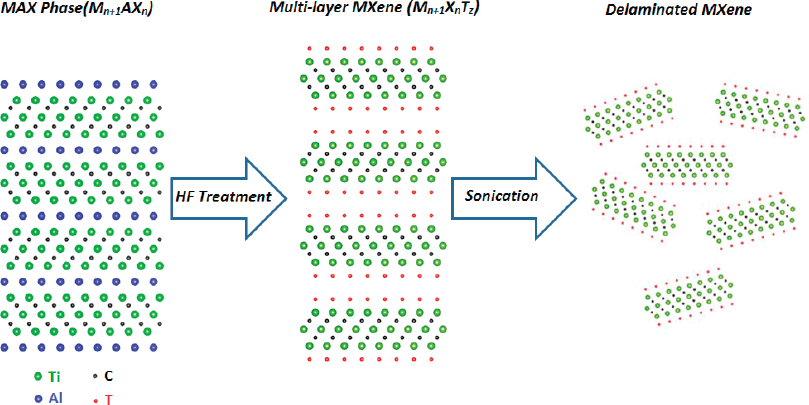
layers are nearly close packed and X atoms fill octahedral sites. Therefore, Mn+1Xn layers are interleaved with the A element, which is metallically bonded to the M element. MXenes are a class of 2D inorganic compounds (i.e., graphene, which is the most famous member of 2D materials family). These materials consist of few-atoms-thick layers of transition metal carbide or carbonitrides (see Figure 6). First described in 2011,7 Barsoum explained that MXenes combine metallic conductivity of transition metal carbides and hydrophilic nature because of their hydroxyl or oxygen terminated surfaces.
Barsoum explained that MXene is produced by etching a MAX phase by using strong etching solutions that contain a fluoride ion such as HF, ammonium bifluoride (NH4HF2), and a mixture of hydrochloric acid (HCl) and lithium fluoride (LiF). MX blocks remain stable and can be separated by sonication, forming 2D sheets called “MXenes.” For example, aqueous HF treatment for “aluminum” containing MAX phases results in selective etching of aluminum. It is the first time that a layered material with very strong primary bonds has been exfoliated. The
___________________
7 Naguib, M., Mochalin, V.N., Barsoum, M.W., Gogotsi, Y., 2013, 25th anniversary article: MXenes: A new family of two-dimensional materials, Advanced Materials 26(7):992-1005.
TABLE 1 Summary of Structure Characteristics and Properties of Two-Dimensional Layers, Including Elastic Properties
| Layer | a (Å) | aMX- aMAX (%) | r (Å) | rMX-r MAX (%) | c11 (GPa) | DOS at EF eV-1 atom-1 |
|---|---|---|---|---|---|---|
| M2AC | ||||||
| Ti2C | 3.007 | −1.08 | 2.291 | 0.9 | 636 (312) | 2.63 |
| V2C | 2.869 | −0.6 | 2.165 | −2.8 | 718 (338) | 1.45 |
| Cr2C | 2.787 | −1.1 | 2.080 | 690 (340) | 2.55 | |
| Zr2C | 3.238 | −1.8 | 2.522 | 0.6 | 594 (261) | 1.77 |
| Hf2C | 3.239 | −1.6 | 2.592 | 2.0 | 658 (291) | 2.25 |
| Ta2C | 3.138 | −0.5 | 2.491 | −1.9 | 788 (334) | 0.89 |
| M3AC2 | ||||||
| Ti3C2 | 3.071 | 0.4 | 4.605 | −1.9 | 523 (368) | 2.19 |
| Ta3C2 | 3.196 | 1.2 | 5.025 | −4.1 | 575 (417) | 1.44 |
| M4AC3 | ||||||
| Ti4C3 | 3.066 | 0.1 | 7.142 | −0.2 | 512 (403) | 1.83 |
| Ta4C3 | 3.172 | −0.6 | 7.804 | 0.3 | 633 (437) | 0.56 |
SOURCE: Michel W. Barsoum, Drexel University, presentation to the workshop, December 9, 2014. M. Kurtoglu, M. Naguib, Y. Gogotsi, and M.W. Barsoum, 2012, First principles study of two-dimensional early transition metal carbides, MRS Communications 2(4):133-137. doi: 10.1557/mrc.2012.25. © Materials Research Society 2012.
MXene family currently includes the following: Ti2C, V2C, Nb2C, TiNbC, Ti3C2, Ti3CN, (V0.5,Cr0.5)3C2, Ta4C3, and Nb4C3 (see Table 1).
MXenes have a much richer chemistry than graphene, and as a conductive layered material with tunable surface terminations, it opens up innovation possibilities in areas such as energy storage applications, composites, photocatalysis, and gas sensors. So far, it has proven to be a better electrical and thermal conductor than titanium, stated Barsoum. It has also shown strong elastic properties. Some have specific stiffness values comparable to Si3N4, which is approximately three times those of titanium. This opens up superb machinability possibilities for MXenes.
Barsoum also said that these materials are corrosion resistant to dilute HCl and H2SO4, hot alkalis, and probably molten nitrogen. Some have even excellent oxidation resistance. They have high fracture toughness: 8 to 16 MPa✓m and a brittle-to-ductile transition at approximately 1000°C. They have fully reversible plastic deformation, with record damping, where damping increases with applied stress squared. Barsoum explained that other properties and applications are still being researched.


