
2
Panel 1: Subsea Fastener Design Requirements
The workshop’s first panel included four speakers who were asked to present on fastener systems in use today for subsea critical equipment oil and gas applications; understanding of the diverse subsea environment in oil and gas drilling operations production; equipment design features and resultant required mechanical behavior for fasteners; fastener material and coating selection criteria; corrosion protection requirements, benefits, and limitations of active and passive corrosion inhibiting solutions; and understanding of all the potential risks, limitations, and failure mechanisms arising from equipment and fastener design, manufacture, material, and coating selection.
POTENTIAL RISKS, LIMITATIONS, AND FAILURE MECHANISMS ARISING FROM FASTENER DESIGN, MANUFACTURE, MATERIAL, AND COATING SELECTION
Tim Haeberle, GE Oil & Gas
Tim Haeberle is chief consulting engineer for materials and process engineering for GE Oil & Gas, where he has been instrumental in developing the company’s engineering policies, procedures, materials and coatings selection guides, and engineering specification systems.
He thanked the National Academies for inviting him and emphasized GE’s commitment to protecting the environment and the safety of oil and gas industry workers around the world. Noting that his own son is a mechanical engineer who
occasionally works offshore on drill ships, Haeberle said he has a personal interest in making sure this work is as safe as possible.
Risks Associated with Bolt Failures
Haeberle began by examining the risks threaded fastener failures bring to subsea drilling equipment. Offshore drilling equipment that contains critical threaded fastener systems includes bolted marine drilling risers, lower marine riser packages (LMRPs), and blowout preventer (BOP) stacks, and the risks of failure vary depending on the type of equipment affected, the fasteners used, where they are bolted onto the equipment, what stage of drilling operations they are used, and other factors.
Specific risks from bolt failures include difficulty in controlling a well; work loss due to surfacing and repairing an LMRP or a BOP; and loss of containment of mud, hydraulic fluid, oil, or gas. These can present major or minor problems; one of the failures described in the Bureau of Safety and Environmental Enforcement’s (BSEE’s) Quality Control Failure Incident Team (QCFIT) report, for example, led to a minor leakage of mud with quick containment, while a worst-case scenario would involve significant leakage of oil and gas with delayed control. In general, Haeberle said, a critical factor determining the degree of risk is fastener location: The closer a failing fastener is to the wellhead, the greater the risk of a major leak that is difficult to control and contain.
Failures on BOP stacks are a particularly important concern. A given drilling operation will have multiple annular BOPs and ram BOPs, and each of these BOPs uses several redundant control systems. The primary control system is two independent control pods operated by hydraulic systems that connect the ship to the drill. There is also an acoustic control pod that can be used if those two systems fail, and a remotely operated vehicle can be used for mechanical control if all of the other systems fail. Taken together, these systems have many bolts in various locations. The most critical components during subsea drilling operations, Haeberle noted, are the hydraulic connectors just under each BOP stack, because these connect the BOP stack to the wellhead at the bottom.
Failure Mechanisms and Options for Mitigation
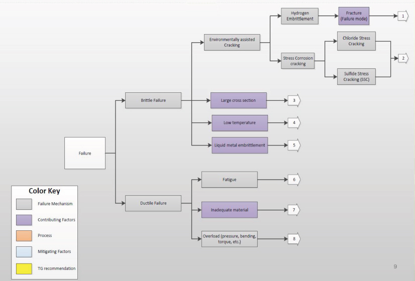
Turning to potential failure mechanisms, Haeberle introduced the work of API’s Multi-Segment Task Group on Bolting, which formed in 2015 and issued a report in 2016 that included detailed mapping of potential failure mechanisms, existing API specifications and industry standards that work well to mitigate the risk of failure, and items and actions other API and ASTM International committees should examine to further reduce failure risks (see Figure 2.1).
The task group’s report was not API’s first take on bolting specifications. API specifications already detail several requirements to reduce failure risks, Haeberle said. For decades, product specifications such as API 6A, API 16A, and API 17D have contained bolting requirements, including maximum design stress limits and quality control requirements. However, Haeberle noted, these specifications do have gaps that hurt the industry, such as a lack of hardness maximum for bolting in API 16A.
More recently, newer specifications such as API 20E and API 20F have specifically addressed material quality in low alloy steel and corrosion-resistant alloys (CRAs), respectively. API 20E, issued in 2012, specified a 34 hydrogen-reduced cracking (HRC) maximum for low steel alloy bolting, reduced from the 35 HRC in API 17D 2nd Edition, in order to limit hardness to prevent hydrogen embrittlement. In the context of this change, Haeberle noted that introducing lower maximum hardness values for bolts without reducing the pressure rating or load-bearing capacity of certain existing components may be challenging.
The API task group also created detailed failure maps, which include a failure’s contributing factors, mitigating factors, and process elements, plus recommen-
dations for improvement. In the upstream oil and gas industry, brittle fracture, specifically hydrogen embrittlement (HE), a form of environmentally assisted cracking (EAC), is much more common than ductile fracture. Therefore, the API task group’s main focus was on factors involved in HE.
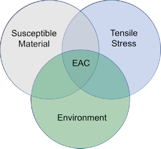
EAC occurs when a material that is already susceptible to cracking is exposed to tensile stress in an adverse environment (Figure 2.2). Controlling the susceptibility of materials is key to preventing environmentally assisted cracking, since it is often more difficult or impossible to fully design for the stresses or the environment to which the equipment is subjected once deployed.
HE tends to occur when bolting has too high of a strength and hardness, and either internal or external hydrogen is present, Haeberle said, noting that other panelists would delve into HE in more detail. The API task force identified several mitigating factors for HE, including selection of materials.
The way the industry has mitigated H2S cracking problems can be used as an example for mitigating HE problems in seawater. NACE MR0175, a document in use for decades (yet frequently updated for newer alloys), provides manufacturers with material processing parameters and helps end users take appropriate precautions in
the presence of hydrogen sulfide. An API task group is working on creating similar guidelines and recommendations for using alloys safely in the presence of seawater.
Finally, the API Multi-Segment Task Group on Bolting Failures also recommended that ASTM unify its guidelines on baking after plating and recommended that zinc plating be eliminated.
Issues Warranting Further Exploration
There are several additional possible contributing factors that the task group has not addressed, including monitoring and recording of cathodic protection (CP) levels for impressed currents and monitoring of risers, BOPs, and LMRPs for stray currents. Because those are operational issues, they are not under the control of API and thus must be addressed by other mechanisms.
Another challenge is determining the appropriate level of maximum hardness, because it is not just hardness, but also a steel’s microstructure, that can impact how it will perform in the field. One of the common materials, AISI 4340, can be processed to a hardness of 38 HRC without becoming susceptible to HE, while AISI 4340 processed to a lower set of requirements or improperly processed, can be susceptible to HE at a hardness of 35 HRC. This example demonstrates that susceptibility is not determined only by a single hardness value, but is also influenced by how the material is processed.
Haeberle stressed the need to better define the limits on corrosion-resistant alloys (CRAs) bolting. The industry currently defaults to NACE MR0175 limits for subsea bolting even though the NACE International limits are intended for hydrogen sulfide service, but newer nickel-based alloys are being considered for potential use in subsea applications, and their properties and susceptibility to HE need to be studied more thoroughly, Haeberle said. The characteristics of certain nickel-based alloys could make them more effective for subsea applications, but they need to have properly defined limits to mitigate risks.
Besides HE, the API task group also examined general stress corrosion cracking. Although this has not been common in seawater exposure, API is nonetheless working on several improvements and has added a note regarding this issue with ASTM A453 Type 660 Grade D bolts. Control of applied tensile stresses, either from makeup stresses or services stresses, is also important.
The size of large cross-section bolts can present particular challenges. Riser bolts are typically large (with a head of 4.75 inches in diameter), and proper material selection and processing to ensure sufficient depth of hardenability are essential to reduce the risk of failure. Insufficient attention to either issue can lead to low-impact toughness or weakened bolts. Subsea hydraulic connector bolts are typically smaller, but thorough hardened ability is also a key issue. 4340 is widely used in these bolts, and it is essential to follow 20E and 20F requirements, Haeberle said.
Low-temperature brittle fracture is not generally an issue for subsea applications. Liquid metal embrittlement is also not a common issue, though the task group did examine it because it can be a concern in bolt manufacturing and bolt lubrication practices. API recommendations should address this issue so that sulfur-based lubricants, as well as lubricants that contain lead, tin antimony, and bismuth, which can cause liquid metal embrittlement, are not used with susceptible materials, Haeberle said.
The task group also addressed bolt fatigue. While fatigue is not a problem in properly torqued threaded fasteners, Haeberle believes that torquing practices across the industry should be reviewed and perhaps addressed by a new API specification, to clear up confusion that can occur when some bolts are preloaded by manufacturers and others are torqued by field operators as well. To reduce failure risks, it is essential to illuminate and communicate proper torquing practices, Haeberle said.
Improper rig operation is another risk that API product specs do not control, but that can result in bolt stress, fatigue, and failure. Haeberle stressed that operational practices should also be examined to reduce added stress on bolts and mitigate failure risk.
Supply chain quality can also be an issue, especially in the era of global sourcing, Haeberle noted. New API specifications and vendor audits under the API Monogram program aim to increase and ensure material quality. While industry adoption of these new specifications has been slower than API would like, it is growing.
The final item the group examined in its failure mapping was tensile stress, which includes overloading, pressure, bending, and torque issues. Over-torquing is the most serious matter and should be addressed, Haeberle asserted, as should any operational practices that would increase tensile stress. Better stress monitoring and recording of stresses on risers such as pull tension, water velocity, and vortex-induced vibration would help identify when fasteners are being subjected to stresses that they were not designed to handle, he suggested.
Wrapping up, Haeberle reiterated that bolt failure on subsea drilling equipment can result in major or minor losses of control or containment and offered a quick recap of the API task group’s 2016 report, which identified multiple failure mechanisms, mitigating factors, and areas of further study. In particular, the task group identified areas where mitigations in current specifications are either nonexistent or insufficient, as well as key knowledge gaps with regard to defining the limitations on low alloy steels and CRA bolting materials.
Numerous API groups are now working to implement these recommendations, and API is also funding research into these issues. Haeberle closed by encouraging workshop participants to review the task group’s report and suggested it could serve as a useful starting point for the National Academies committee’s work.
FASTENER SYSTEMS IN USE IN CRITICAL EQUIPMENT AND THE DIVERSE ENVIRONMENTS IN SUBSEA OIL AND GAS DRILLING AND PRODUCTION
Khlefa Esaklul, Occidental Oil & Gas
Khlefa Esaklul, corrosion and materials adviser at Occidental Petroleum Corporation, specializes in corrosion management, materials selection, asset integrity, and failure analysis for oil and gas operations. He was recently appointed chair of the Technical Coordination Committee of NACE International (formerly the National Association of Corrosion Engineers). He presented key challenges to using bolts, offered his conclusions about bolt characteristics, and raised several issues NACE and other bodies can tackle in order to reduce bolt failures.
Fastener Challenges
Esaklul emphasized that new challenges are emerging as subsea explorations expand into deeper water depths and encounter environments with higher pressures and more extreme temperatures, hydrogen sulfide concentrations, carbon dioxide concentrations, and so on. Today’s equipment must be far more complex, with each component requiring material with higher thickness, strength, and resistance to cracking. He noted that while 10 years ago, subsea drilling was done at a maximum of 7,000 feet below sea level, companies are now routinely drilling more than 10,000 feet, with one vessel targeted to operate at 12,000 feet.
Bolts are essential to subsea drilling for many reasons; flanged connections—complex pieces of equipment requiring many fasteners—are integral to equipment for both drilling and production. Offshore drilling risers are extremely large and complex structures that vary greatly in size and include multiple flanges and bolts. Offshore oil production equipment relies on the same materials and fasteners. An important difference is that while drilling risers are meant to operate for a limited time, production equipment is generally meant to be permanently installed for the lifetime of the oil field.
Deepwater reservoirs, which are subjected to higher water pressure and more extreme temperatures, require materials with properties that exceed what is commonly in use today. Safety requirements, environmental regulations, and cost considerations throughout the industry also increase the need for reliable parts. For all of these reasons, dependable fasteners of all types, sizes, and uses are integral to any drilling operation.
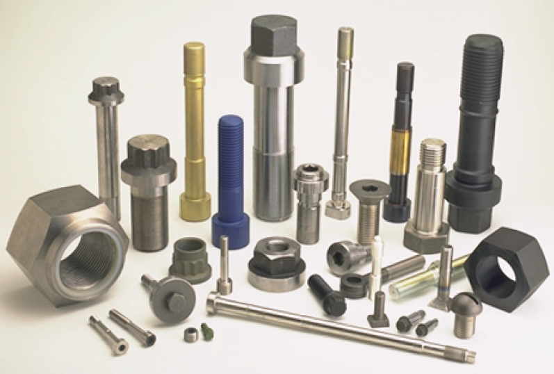
High-strength fasteners come in a range of sizes (Figure 2.3) and are used in many different pieces of equipment, including risers, connectors, BOPs, subsea assemblies, trees, wellheads, flanges, and internal valve connections. Larger bolt sizes
(exceeding 2.5 inches) are becoming more common. Most fastener components are also protected with CP via anodes, some of which are placed very close to flanges.
Choosing the Right Materials
The criteria for selecting bolt materials focus mainly on mechanical properties, such as strength and toughness; corrosion resistance, particularly with CRAs; and resistance to EAC, such as stress corrosion cracking, HE, or sustained load cracking. Engineers must weigh many considerations in order to select the appropriate fastener materials, including loading and environmental conditions. Loading conditions can be static (e.g., applied weight, fluids columns, and pressure) or dynamic (e.g., ocean current, wave action, and vortex-induced vibration). External environmental conditions must also be considered, such as water salinity and temperature, CP interaction, and stray currents. Internal environmental factors include the fluids used for drilling as well as the production fluids that interface with the inside of the equipment. All of these factors impact material performance.
A particularly difficult challenge, Esaklul said, is the extremely limited ability
to access, monitor, and maintain subsea equipment once in use. Engineers aim to build equipment that is inherently reliable because this equipment is often inaccessible for routine maintenance or inspection.
Esaklul highlighted several categories of materials that are currently in use or that have been considered for use in subsea fasteners. These include steels, stainless steels, nickel alloys, cobalt-nickel alloys, beryllium-copper alloys, and titanium alloys.
High-strength steels combined with CP have been found to be susceptible to stress corrosion cracking and HE. In fact, their susceptibility to cracking increases as their yield strength increases. Steels with a yield strength below 120 thousand pounds of force per square inch (ksi) are generally resistant to EAC, but above 120 ksi, resistance decreases as strength increases. However, it is possible to find the right balance. Esaklul noted that past NASA research determined that 4340 steel, without CP, is resistant to stress corrosion cracking up to a tensile strength of 180 ksi.
Research published in the ASM International textbook The Atlas of Stress Corrosion and Corrosion Fatigue Curves shows a compilation of material performance in a variety of environments.1 The findings show that going above 150 ksi renders materials less usable in these environments; similar conclusions were reached by Chung and Gangloff.2,3 The basic takeaway from this work is that exceeding 150 ksi generally makes it significantly more challenging to select materials that can be used for purposes requiring high strength.
In the past, the limitation on materials hardness exposed to CP, 22 HRC, was found to be overly conservative, Esaklul noted. The current recommended practice for subsea fasteners made of high-strength steel is between 34 and 35 HRC. This limit has been successful and has been adopted by various standards committees, including API and NORSOK. For CRA materials, the industry follows NACE’s maximum hardness requirement because there is not enough data showing success past that limit.
Qualification testing has long been in place to verify that materials will work under specific conditions. However, establishing the most reliable testing methods is a challenge, especially for assessing HE susceptibility after CP exposure. Despite extensive tests, there remains no material that is totally immune to hydrogen embrittlement, said Esaklul. That said, an indication that a material is susceptible to HE does not mean that a fastener will fail. Esaklul reminded participants that laboratory tests revealing HE susceptibility are not necessarily a reflection of in-
___________________
1 A.J. McEvily, ed., 1990, The Atlas of Stress Corrosion and Corrosion Fatigue Curves, ASM International: Materials Park, Ohio.
2 Y. Chung, 1984, Threshold Preload Levels for Avoiding Stress Corrosion Cracking in High Strength Bolts, Tech. No. 0284-03 EV, Bechtel Group, San Francisco, Calif.
3 R.P. Gangloff, 2003, Hydrogen Assisted Cracking in High Strength Alloys, pp. 31-101 in Comprehensive Structural Integrity (J. Petit and P. Scott, eds.), Elsevier Science, New York.
dustry experience in the field. Rather, the fact that very little failure is seen overall in use is a good indication that fasteners are subject to more severe conditions in testing than in the field.
A recent paper delivered at the NACE conference, for example, concluded that of four different nickel alloys in successful operational use, none are completely immune to HE. Like other metals and alloys, as strength increases so does HE susceptibility. This principle is true of the 18 fastener materials currently in use, Esaklul said. Precipitated hardened nickel alloys have some potential but are much more expensive than low alloy steels. Of hardened stainless steels, Esaklul said A286 works well, and some titanium alloys also have promise, although their applications are more limited.
Corrosion control is a separate issue for engineers to solve. Above water and in the splash zone, coating is essential, and for subsea corrosion, CP with no coating is generally the preferred protection. Most fasteners are coated prior to installation and CP activation. However, CP performance can vary near anodes or in the case of unpredictable environmental stresses, such as impressed or stray currents. There are several coating options with various temperature limits, but the most common coatings are zinc electroplating, hot-dip galvanizing, Xylan, and phosphating with or without zinc.
Unresolved Questions about Fastener Failures
Although bolt failure is a serious issue, Esaklul said that right now we are seeing fewer failures than have been predicted. He suggested several possible explanations. Perhaps bolts are under less stress than their worst-case-scenario designs anticipated, perhaps they are shielded from adverse CP effects through isolation or grease packing, or perhaps testing conditions are more severe than actual conditions. However, recent failures are suggestive of a rising problem as companies continue to drill deeper and water conditions change.
More than a decade ago, Esaklul examined the use of 34 HRC-specified bolts and found that despite their use in a range exceeding 34 HRC (from 35 to 39 HRC), the bolts performed well, with no failures. Recent failures could be due to a fastener’s load, materials, or environmental conditions, or, more likely, a combination of all three, Esaklul speculated. Load, conditions, and environmental stresses will all become more extreme as drilling goes into deeper water. HE susceptibility increases with stress levels; cases have shown, for example, that loading an X750 bolt to 80 percent of the yield strength or higher with severe CP can contribute to failures. Over-torquing such bolts on wellheads in the Mediterranean Sea has reportedly led to failure of wellhead equipment.
Quality assurance alone is insufficient to control strength. While materials may be specified at 34 HRC, Esaklul’s research reveals that there is quite a bit of variation
in practice. But because there had not been any known failures, this variation was previously dismissed as not a significant safety issue. Other variables to consider include CP protection, zinc coating, and anode interactions.
Despite few failures, Esaklul emphasized that alloys for subsea use must adhere to materials specifications and quality assurances for heat treatment, cold work, and maximum hardness to ensure EAC resistance. To ensure HE resistance, even tighter specifications may be needed. There are many materials to choose from, but the challenge is to select one that both resists EAC and is cost-effective.
In closing, Esaklul summarized his remarks, stating that there are many materials available for high-strength subsea fasteners, but there is a need to know more about their HE resistance and the effects of coating, specifically for high-strength steels. There is also a need for better monitoring of CP protection and any potential interference.
Another unresolved issue is the effect of thread cutting versus machine rolling during manufacturing. Craig’s recent article on this topic outlined challenges to accepted manufacturing processes.4 There is also more information needed to determine how ocean currents or vortex-induced vibration affects drilling risers.
On the whole, several issues require more clarity, and the industry and standards bodies must create tighter material and manufacturing specifications and better quality control to ensure their use, Esaklul concluded.
HIGH-STRENGTH BOLTING VERSUS SUBSEA SERVICE CONDITIONS
Russell Kane, iCorrosion, LLC
Russell Kane is president of iCorrosion, LLC, a corrosion and materials consulting agency that specializes in materials design, corrosion prediction, and failure analysis. His presentation focused on the environmental conditions in which high-strength bolts are used, including sources of hydrogen and sources of variability in the subsea drilling environment.
Trained as a structural engineer, Kane recalled that in his first job (with ExxonMobil) he was immediately sent into the field, where he got a perspective unusual among Ph.D. engineers: that of an end user operator. That hands-on experience in the service environment, he reflected, was perhaps more valuable than any book learning and has formed the basis of his career. It was in this context, for example, that he grasped the implications of “process creep”—a phenomenon common in the field but often overlooked by engineers—in which operators make small changes to the way a tool or process is used, often without realizing it. These
___________________
4 B.D. Craig, 2015, On the contradiction of applying rolled threads to bolting exposed to hydrogen-bearing environments, Oil and Gas Facilities 4(06):66-71, doi:10.2118/178431-pa.
small changes accrue until eventually the equipment is routinely being operated outside of the conditions or assumptions for which it was designed. To Kane, this story underscores the importance of understanding the operational context and environments in which equipment is used, and not just the context and environments it is designed for.
Causes of Hydrogen Embrittlement
As discussed by other speakers at the workshop, bolt failures can happen through a variety of mechanisms. Ductile failure can result from overload, fatigue, or the use of insufficient materials. Brittle failures are caused by low toughness or EAC. In his presentation, Kane focused in particular on EAC, specifically HE but also including chloride or sulfide cracking.
Expanding on the illustrative diagram other speakers presented, Kane pointed to three causes of HE: environmental conditions that create a hydrogen source, stress intensity from sustained heavy loads, and a susceptible material. All three elements must be thoroughly examined in order to resolve HE, he said.
Each aspect has its own set of complexities. Environmental conditions, for example, can include multiple potential sources of hydrogen in the context of different applications, and the duration and intensity of the exposure can also vary. Loads are also complex. For example, they can be static or dynamic, currents can loop, and bolts can be over-torqued. What makes a material susceptible also depends on a number of factors, although most engineers focus on hardness.
Sources of Hydrogen
Hydrogen is a small atom that diffuses easily in steel. In other alloys where it does not diffuse, it is very soluble. It causes brittle fractures, which can result in sudden, catastrophic operations failures. As other speakers mentioned, increasing strength or hardness of a material typically increases its susceptibility, though HE can also be a problem in low-strength materials.
There are many different sources of hydrogen, and it takes only a small amount to induce EAC. Plating during manufacturing, especially processes involving a cathodic current, can generate hydrogen ions. Hydrogen can also come from acid cleaning with anodes. Once hydrogen enters the material, subsequent coating can inadvertently ensure it is locked in place. In these scenarios, Kane stressed, hydrogen is present even before a bolt goes into service. Certain processing methods can also help to expel hydrogen, as in some baking regimens recommended in ASTM E850, or hot-dip galvanizing.
Once the bolt is deployed in the subsea application, CP can be a hydrogen source. There are two types of CP, impressed current and sacrificial anodes. They
work differently, but ultimately they both transfer currents, an act which generates electrons that can create hydrogen. Zinc plating on bolt threads also brings an anode and a cathode into close contact, generating a current between them, another potential hydrogen source.
Kane pointed out that much of the research engineers rely on today is from the 1960s, 1970s, and 1980s. While it is quality research, he suggested that new work would be useful, particularly research focused on external hydrogen and CP as they relate to deepwater applications.
One influential study, published in the early 1970s, revealed a “sweet spot” at −850 mV when high-strength steel is cathodically protected from corrosion and generates minimum hydrogen.5 Guidelines specifying this level can help, but unfortunately −850 mV is hard to achieve across all conditions. Straying too high generates hydrogen and leads to HE; straying too low invites corrosion, which also generates hydrogen. All of this, Kane concluded, demonstrates that sources of hydrogen in the environment are just as important as qualities of the material itself.
Sources of Variability
The undersea environment encompasses a wide range of environmental conditions. When drilling in warm, shallow water, such as parts of the Gulf of Mexico, there are relatively few barriers to effective CP thanks to higher concentrations of oxygen and because of the protective calcium layer that naturally accrues on cathodes in alkaline, calcium-rich water, which reduces the current demand and helps anodes last longer. In contrast, the waters of the North Sea are cold and move at a high velocity, causing anodic corrosion at a higher rate, resulting in higher current.
But even in those harsher North Sea conditions, drilling in relatively shallow water does not require high-strength bolts, and there have not been many bolt failures. As other speakers mentioned, deeper water brings new challenges. Water deeper than 5,000 feet, Kane explained, introduces different ranges of temperature, pressure, and flow that can counteract cathodic protection and prevent the formation of a protective calcium layer, increasing the current demand on CP, which in turn increases the potential for HE. Other factors that can increase CP current demand include low oxygen concentration, low water temperature, lateral currents, and anodes and cathodes positioned too closely together.
The document NACE SPO176 2007 contains the most recent guidelines for CP. While we tend to think of CP in terms of potential, Kane said, CP current demands
___________________
5 G. Sandoz, 1972, High Strength Steels, pp. 79-145 in Stress-Corrosion Cracking in High Strength Steels and in Titanium and Aluminum Alloys (B.F. Brown, ed.), Naval Research Laboratory, Washington, D.C.
are more important in determining the production of hydrogen and the consumption of the anode. While the South China Sea and the Gulf of Mexico show more moderate current demands, the Cook Inlet, with its cold, turbulent, fast-moving water and high levels of particulate matter, quickly erodes any calcium film and increases the current demand. That, Kane posited, is an environment reflective of what we can expect more of as subsea drilling goes deeper.
The bottom line is that each location has its own set of environmental variables (including water resistance, temperature, turbulence factor, lateral water flow, current density, and design slope) to which fasteners will be subjected. Deep water brings low temperature, which, among other effects, reduces the potential for a protective calcium film. It also increases hydrostatic pressure, demanding a higher CP current. This can lead to an overreliance on sacrificial anodes, which were originally meant for 5 to 10 years of use, in deepwater equipment expected to be in place for decades. All of this, Kane said, increases the likelihood of HE.
In 1975, Townsend’s work on high-strength steels concluded that stress intensity and hardness are linked and that despite zinc coating, exposure to seawater will inevitably lead to HE.6 Knowing this information, the remaining question is where to draw the line on the hardness of bolts. Should engineers design for all worst-case scenarios, or only work to address the conditions in which we’ve seen bolt failures so far? In addition, a material’s hardness measure is only one characteristic among many. Does a limit of HRC 32-34 make sense for all subsea fasteners, given variations in material type and quality, criticality level, and service conditions?
CRAs are also susceptible to HE under CP because of their composition, microstructure, and hardness, as described previously by Esaklul. Kane noted that while one alloy, A286, was most resistant to HE in NASA testing, it was susceptible to chloride stress corrosion cracking. This example illustrates that while HE is a primary concern, hydrogen stress cracking, sulfide stress cracking, and liquid metal embrittlement should not be discounted as potential mechanisms of failure.
Wrapping up, Kane reiterated the need to investigate all three elements that contribute to EAC: the environment, stress, and susceptible material. Removing any one of these factors from the equation can dramatically reduce the threat of HE or other forms of EAC. Focusing on environmental conditions, Kane stressed that subsea conditions vary considerably based on their location. With deeper drilling comes changes in environmental conditions, material requirements, and risks, which in turn affect the likelihood of HE. While standards for materials and their use are still evolving, more research is needed to understand how CP can define material limits and processing conditions.
___________________
6 H.E. Townsend, 1975, Effects of zinc coatings on the stress corrosion cracking and hydrogen embrittlement of low-alloy steel, Metallurgical Transactions A 6(4):877-883, doi:10.1007/bf02672311.
BOLT DESIGN FOR HIGH-POWERED SHIP PROPELLERS
Hilmar Stefansson, Rolls-Royce Naval Marine
Hilmar Stefansson recently retired after a career spanning more than 40 years at Rolls-Royce Naval Marine, where he was a propulsion engineer. He designed, built, and evaluated high-powered marine propulsion systems, specifically the high-powered propellers, fastened with bolts, that drive large U.S. Navy warships.
Propeller Components
Stefansson’s particular expertise is in large controllable pitch propellers for destroyers and other combatants, which operate at up to 60,000 horsepower, are powered by two turbine engines, and weigh approximately 30 tons each. The propellers range from 10 to 23 feet in diameter. The propellers, made of a nickel-aluminum-bronze alloy, consist of individual blades secured to a central hub mechanism of the same material and come in four- and five-blade configurations. The propellers are used to propel the ship throughout the speed range, but the controllable pitch mechanism is particularly used for slow speed maneuvering and to stop a ship or to change direction through the rapid change in pitch of the blades. While these maneuvers can impose significant stress, a full power turn at maximum speed is the most stressful condition for such a propeller.
The hub is hydraulically operated, and while the entire system has many bolts, eight bolts on each blade mounting flange are deemed critical. As an example, if each propeller has five blades, and there are two propellers per ship, that is 80 critical bolts on each ship, Stefansson noted. These bolts receive the most attention of any system component, because if one bolted joint fails, the blade or even the whole propeller can fail.
Such a failure would require a dry-dock repair, taking weeks and costing millions of dollars. Perhaps worse than the financial cost is the loss of a manufacturer’s reputation after such an event, Stefansson noted, pointing to a case in the 1970s in which a failure was discovered in all five blades of a propeller. The manufacturer of the faulty propeller never received another order and soon went out of business.
Evolution of Bolt Design
For Rolls-Royce Naval Marine, fatigue is considered to be the predominant design challenge for underwater bolts, even more so than corrosion. Stefansson described a unique bolt design used by Rolls-Royce, made of K-monel, a nickel alloy. While this material doesn’t have the level of yield strength seen in other types of bolts, the bolt uses a very different design that omits the hex head typically ex-
pected on bolts. Instead, it has a threaded head. The bolt is stretched hydraulically, threaded into the hole, and locked into place with a preload when the hydraulic pressure is released.
Rolls-Royce took this unusual approach, Stefansson explained, so as to avoid relying on torque, which cannot be fully controlled. Stretching, on the other hand, guarantees the right level of stress preloaded joints need. He noted that extensive Navy-sponsored studies support this design. In addition, Rolls-Royce collected data from full-scale testing, in which a full-sized propeller and its blades were connected to various instruments that measured stress levels when the ship performed high-speed maneuvers such as full power stops and turns.
The first-generation design for these bolts, known as Morgrip from the United Kingdom, came out in the 1970s, and Morgrip bolts were used successfully in more than 200 propellers. The second-generation design was developed in the late 1980s, when propellers got bigger and blades got heavier, adding demands that exceeded the capabilities of Morgrip bolts. For this second-generation design, Rolls-Royce chose an Inconel alloy for the material, which has a yield strength of 150 ksi. In this model, the threads are rolled—after age hardening, Stefansson emphasized—and there is a large fillet under the head, which reduces stress concentration on the head. Additionally, to distribute the stress more evenly over the bolt threads, reverse taper threads were used. In a normal threaded fastener, stress is mostly taken on by the first two threads. In the reverse design, the stress load is pushed further down the bolt, making it more evenly distributed. Finally, these bolts are about an inch and a half longer than the Morgrip bolts, because longer bolts are less stiff and distribute joint loads better, allowing a more even sharing of load between the joint members and the bolt.
One consequence of all of these design changes was that the second-generation bolts were not able to be hydraulically stretched. The team returned to conventional torquing, but still relied on stretch, which they measured with a depth dial gauge, to keep the bolt secure. If the stretch was measuring too low, the torque was increased within an acceptable range to achieve the desired value (currently 0.007 to 0.009 inches).
After designing the second-generation bolts, the team again conducted full-scale bolt fatigue testing to assess every new feature that had been added. After the bolts were put into service, the team followed up by measuring real-world stress loads and even conducted full-scale comprehensive fatigue testing. The new design features were a success, and in fact one second-generation bolt worked so well that it broke the machine used to test it.
One key lesson pervading the Rolls-Royce experience, Stefansson said, is that it is impossible to prevent moisture from entering an underwater system. For example, Morgrip bolts, originally made of steel, were fitted with caps in an unsuccessful attempt to keep water out, but moisture was still able to enter past the
rubber O-rings around the bolt. As a result, moisture must be accounted for in a bolt’s design; for the Morgrip bolts, this was accomplished through the use of K-monel material in lieu of steel.
A Rigorous Design Process
Stefansson offered an overview of the Rolls-Royce bolt design process. The process begins with the propeller’s particulars, such as power, RPM, and diameter. The team then conducts a computational fluid dynamics analysis to predict both steady and alternating propeller loads. They then generate the blade design and build 3D Computer-aided Design (CAD) models of the hub, blades, and bolts. Finite Element Analysis software lets them model full power ahead and full power turning load scenarios.
Those results are compared to an S-N curve, developed from full-scale bolts and not scale or rotating beam tests, and cycles to failure are calculated to estimate the life span of the bolt. The target life span is 30 years, a span that the equipment frequently exceeds in practice. The actual life span typically depends on how a ship is operated; while full speed ahead will not result in fatigue failure, full power turns impose a much greater level of stress. Stefansson noted that ships rarely perform full power maneuvers, however, because of the enormous amount of fuel they consume.
Instead of zinc coating or other types of plating, Stefansson said Rolls-Royce uses a thin copper flashing (0.0002 inches) along with anti-seize pastes to lubricate the threads and prevent galling on the bolt. Copper works well for this purpose, he said, and in addition it has an affinity for hydrogen so it acts as a sponge between the threads, reducing the likelihood of hydrogen embrittlement in the bolt material itself. Before bolts are installed, and whenever they are removed for maintenance, engineers test for cracks. Any cracked or otherwise defective bolts are replaced.
While the bolts Stefansson developed over the years have never been involved in a fatigue failure, bolts have sometimes been reported loose or even missing. Because the design relies on friction torque and not thread locking to keep the bolts in position, it is a mystery how bolts get so loose as to disappear, Stefansson said. Installation or maintenance error may be a contributing factor; Rolls-Royce often relies on U.S. Navy divers to replace blades or reinstall bolts under water and does not directly conduct quality control. To combat this loosening, engineers increased preload, and so far there appear to have been no more loose or missing bolts.
Before closing, Stefansson described the single hydrogen crack he experienced in his time at Rolls-Royce. It was on a K-monel bolt installed on a small propeller that was highly loaded. Stefansson theorized that the hydrogen was generated from an impressed current CP system, which is present on all ships. In his experience, manually adjustable impressed current systems are easy to overuse, and he suspected that too much current might have contributed to this instance of HE.
Luckily, the cracked bolt was found during routine maintenance and did not cause the failure of a blade or the propeller.
PANEL 1 DISCUSSION: SUBSEA FASTENER DESIGN REQUIREMENTS
Thomas Eagar, Massachusetts Institute of Technology, moderated an open discussion following the workshop’s first panel on Subsea Fastener Design Requirements. He began with a brief overview of the panel presentations: Haeberle detailed API’s standards to mitigate bolt failure; Esaklul covered the material characteristics required for successful fastener performance; Kane described the environmental conditions that bear on bolt performance; and Stefansson discussed the design and testing process for undersea bolts in the context of ship propellers.
Several trends emerged in the discussion. Participants asked questions about standards and techniques for manufacturing materials and bolts, understanding the impacts of stress loads and torquing, understanding practices and effects related to CP, and broader questions about how failure investigations are conducted and what may be learned from them. A common theme among all of these areas was the need for more research.
Hardness of Materials
Manuel Maligas, Trendsetter Engineering, asked Haeberle to clarify the API committees’ work on bolt manufacturing standards, specifically whether the 35 HRC limit for subsea bolts was still in place. Haeberle confirmed that API 17D limited all steel components (not just bolts) to the 35 HRC maximum in order to prevent HE.
Maligas recalled that in 2003 a bolt that failed on BP’s Thunderhorse riser exceeded 35 HRC, despite this limit, and noted that the BP Thunderhorse incident was not the only such example. Haeberle confirmed BSEE’s QCFIT report that the failed bolt was above 35 HRC. He then speculated that while the 35 HRC limit is in 17D, which covers subsea production equipment, those bolts could have been manufactured according to 16A, which covers drill-through equipment and has different specifications. Eagar weighed in to note that controlling hardness alone is not the sole solution to HE.
Timothy Foecke, NIST, asked via conference line how confident the panel was about the correlation between hardness and performance. In his experience at NIST, performance is instead related to operations procedures or calibrations. In fact, NIST has had little success, in 90 years of research, at finding a consistent correlation between hardness and mechanical properties. Kane responded that some of API’s recent work seeks to address that issue. 20E, for example, includes a maximum hardness as well as maximum variation for that hardness. Decades ago,
the focus was on improving material quality, reducing variation in hardness, and ensuring consistency. Kane expressed his belief that the field should still pursue these goals and that 20E is a step in the right direction.
Material Quality
Clyde Briant, Brown University, asked Haeberle to expand on his remarks about the preparation of the steel and whether enhancing quality could increase hardness maximums. Haeberle remarked that the manufacturing equipment, the bolt designs, and many of the specifications in use today are from the 1970s and 1980s, though they have been revised significantly over the decades. API’s 20E has tried to address these revisions by thoroughly reexamining manufacturing processes like casting, melting, forging, and heat treatment. Haeberle also noted that banding is particularly challenging with low-alloy steel and can result in inconsistent hardness measurements within a single piece of material. Briant noted that in the 1980s and 1990s, EPRI (the Electric Power Research Institute) sponsored research to create best practices for steel processing to reduce cracking.
John Scully, University of Virginia, asked the panel why the metallurgical standards change so frequently and whether this constant change might make it more difficult to determine exactly which variables contribute to HE or its prevention. Haeberle clarified that most revisions are internal to API, not issued externally to manufacturers, and noted that there is a feedback loop among suppliers, vendors, and API, though he acknowledged that this exchange may not achieve the level of rigor that would be expected in a true scientific study investigating the root causes of HE in different materials.
An unidentified participant weighed in, noting that her research on microstructure has revealed that strength has a first-order effect. Strength is calculated by measuring hardness, which is imprecise. To get an exact measurement, full-scale stress testing is necessary, but inconvenient, which is why engineers rely on the hardness measurement. The second-order effects are a function of microstructure. Hydrogen can be beneficial or harmful, and there remain many unanswered research questions in this area, she said. While she stressed that only full-scale testing can ensure true quality control of the material (rather than hardness alone), she added that other techniques, such as impact energy tests, can also help us understand hydrogen behavior and detect HE susceptibility in poorly manufactured material.
Esaklul expressed his belief that there has been an overreliance on the Charpy impact test to characterize materials and perform quality controls. Instead, he suggested, the field needs to delve further into the metallurgical conditions and microstructure of materials. He recalled research from the 1970s that came to a similar conclusion. Engineers need to combine impact plus classical fracture toughness data to ensure quality control for such crucial equipment, he said.
Brun Hilbert, Exponent, asked if the price difference between a titanium bolt and a steel alloy one was significant, given that BOPs cost tens of millions of dollars already. Eagar answered that titanium is 50 to 100 times more expensive.
Kane noted key differences in the manufacturing of production equipment and drilling equipment. Drilling equipment has a higher hardness because it was made for short-term use and in shallower waters. Today, we are drilling in deep water, the same equipment is expected to last years, and it is considered critical. These new, enormous, 10,000-foot-long machines have hundreds of variables, yet engineers still rely on research from the 1960s, 1970s, and 1980s. More updated research is needed, he said.
Coatings
Jyotirmoy Mazumder, University of Michigan, noted that all the speakers pointed out that zinc coating is a source of HE, yet zinc-coated bolts are still in service. He asked if there was a plan to replace those bolts, or whether the specification only addressed new bolts.
Haeberle replied that while some bolt failures from BSEE’s QCFIT report were zinc electroplated, not all subsea bolts are. In fact, zinc was never the only coating used. Bolts are often coated with Xylan, oil, or phosphate, and researchers are studying other materials’ potential as well. Cadmium coatings have been banned for environmental reasons. He noted that finding the right coating is difficult; it has to be thin, provide lubrication, prevent corrosion, allow electrical continuity, accept CP, and still conform to American National Standards Institute (ANSI) and ASTM standards. An unidentified participant added that each of these different coatings has a different friction coefficient, which means the amount of torque for each one would vary, adding more complications.
Thread Rolling
Bob Schafrik, GE Aviation, asked the panel whether compressive residual stress on rolled threads reduced a bolt’s HE susceptibility. If that is the case, why, he posited, aren’t we studying rolled threads more? Kane replied that where there is compression, there is always tension somewhere else. Hydrogen can invade that area of tension and lead to HE. Cold work, however, alters the physical properties of metal and can reduce hydrogen in a bolt’s modified microstructure.
An unidentified participant remarked that several unpublished studies have shown that rolling threads after heat treatment brings significant benefits. Part of the reason is that the cold work process introduces dislocation, which makes it harder for hydrogen to move within a material, decreasing its presence. Continuing this line of research could be very promising.
Stress Loads
Pol Spanos, Rice University, pointed out that the stress loads the Navy experiences are more predictable than the oil and gas industry because of factors such as water currents, waves, and other types of vibrations. He asked Stefansson what sort of safety factors Rolls-Royce considered when measuring stress loads for the Navy context.
Stefansson replied that Rolls-Royce was required to put safety factors on all fasteners. Fatigue measurements come from actual test data, ideally full-scale. Spanos wondered if it was possible to develop a holistic assessment to measure risk in the context of oil and gas installations, despite the unpredictability of the ocean environment. Trent Fleece, BP, noted that BOP equipment can have a load rated to 10 to 15,000 psi, which is orders of magnitude greater than the environmental loads. After the 2003 riser failure, BP added instrumentation to record and analyze riser data, such as daily loads, wave action, and displacement. These measurements are their safety factors. The topic was further discussed in Fleece’s presentation on Day 2 of the workshop.
Torquing
Hilbert asked if it is true that ductile failures are much rarer, and whether this is because there is enough yield strength in the material. Esaklul assented, noting that ductile failures result from over-torquing bolts.
Nancy Cooke, Arizona State University, asked for more information about over-torquing and torquing best practices. Haeberle replied that torquing is very difficult to do right, and both under- and over-torquing are common and harmful. He said the best practice is to take the time to measure the extension in every bolt, if a bolt placement allows it (which is not always the case). Time can be a barrier, however. While best practices may be followed faithfully in a factory, he said procedures might be rushed when a rig is in operation.
Stefansson added that the primary reason for torquing is to apply the proper preload to a bolt. Tightening it is only a secondary condition. Noting that torque is a coefficient of the diameter of the screw times the force on the bolt, he said that unfortunately, the coefficient varies considerably. He then pointed to lubrication as a key source of variability, noting that he once had to demonstrate to a worker how to properly and thoroughly lubricate an entire bolt with a paintbrush, not a finger. Fully applying lubricant makes a huge difference in the amount of torque, he said. This lack of technical knowledge is another reason Rolls-Royce prefers not to rely on torque to hold bolts in place. He also noted that while Rolls-Royce often uses high-torque wrenches, engineers are careful not to be overly dependent on them. The torque set by these wrenches can alter depending on the time of day,
weather conditions, or the strength of the person using the tool. For this reason, Rolls-Royce usually sends a company technician to oversee bolt installation, he said.
James Jennings, Naval Surface Warfare Center, offered the opinion that torquing receives so much attention because it is easy to measure, and torque wrenches are easy to use. However, he agreed that the preload is more important and that torque can add unwanted variation to a preload. Even a good mechanic adds 5 percent variation, plus or minus, and the industry rule of thumb is plus-or-minus 20 percent. Unfortunately, it’s not easy to measure preload, he said, and while Rolls-Royce measures stretch, that is also a difficult proposition. Complicating things further, torquing and measuring one bolt also affects all the other bolts. It is therefore difficult and time-consuming to get all the bolts in a connection properly balanced.
Cathodic Protection
Frank Adamek, Adamek Engineering and Technology Solutions, LLC, noted that HE failures started occurring around 2000, when ships switched from anodes in the hull to impressed current systems, and inquired about the voltage level used for the ship that experienced the cracked propeller Stefansson had mentioned. Stefansson replied that the Navy generally limited overvoltage, considering 1 volt the maximum acceptable.
In a similar vein, Scully noted that in the field he has seen the electrochemical dependency that Kane characterized as the “sweet spot” of −850 mV, where materials are protected from HE. The industry would benefit, he said, from failure mapping of proximity to anodes or impressed current systems even within this sweet spot. Kane replied that some of that has been tried in failure investigations. Unfortunately, there are a lot of unanswered questions. For example, what is the current distribution of that particular bolt? Is CP helping or not? Today, systems are being designed to last a long time, with more currents being used in smaller places, despite all that we have yet to understand about how steel behaves in deep, cold water.
Most of the time impressed current works well, Kane said, but there are gaps in the data. Impressed current has few limits on how much current it provides, resulting in periodic variability. There are other variables as well, including water pressure, flow, and anode consumption. Stefansson noted that impressed currents diminish as they travel farther from their source and can’t protect anything inside a closed structure. Kane mentioned that CP is usually used to protect the upper BOP stacks, and anodes protect systems closer to the bottom of the ocean floor, but we don’t necessarily know how well these systems coexist.
Jon Shoemaker, Diamond Offshore Drilling, asked if the distance of impressed current reference cells had ever been studied, and particularly whether the dissipa-
tion rate was affected. Haeberle replied that there are several ways to do a survey on a working riser, whether because an issue was reported or for routine maintenance. Remote operated vehicles can measure the level of CP, though Haeberle acknowledged that results can vary widely.
Following up, Shoemaker asked if anodes installed on the BOP experienced corrosion and whether that could be avoided. Kane responded that underprotection can be just as bad as overprotection. CP is complicated, with variation between how much current is running, how much hydrogen is generated, and whether bolt coatings are affected. There are no easy answers, he said, especially when operating in deep water.
An unidentified participant asked whether the interaction between fixed anodes and CP could affect bolt performance. Esaklul answered that one of his main concerns is that we don’t know exactly how the two systems interact, and more monitoring is needed to determine that and other possible effects of the interaction.
Failure Investigations
David Matlock, Colorado School of Mines, asked Esaklul to expand on his claim that there were fewer failures than predicted and to explain how those predictions were reached. Esaklul explained that while testing identifies materials that are susceptible to HE, these same materials have been successful in service despite their known susceptibility. He expressed his belief that the increase in bolt failures since 2003 is connected with the fact that operations have moved into deeper water.
In response to an unidentified participant’s comment about the effect of voltage on hardness, Kane reiterated that in the HE Venn diagram, the factors do not act in isolation. Each element affects the others. This is a multidisciplinary problem, which is part of the reason that it hasn’t been solved yet.
Salim Brahimi, Industrial Fasteners Institute and ASTM Fasteners Committee chair, remarked that while occasional failures are often identified by their failure mechanism, such as stress corrosion cracking, HE, or fatigue, often the root cause isn’t correctly identified. Examples of root causes, he explained, might include poor manufacturing processes, improper heat treatment, or the quality of the material. Brahimi stressed the need to be able to control these procedures to ensure uniformity and asserted that the emphasis of failure investigations should be on root causes rather than mechanisms of failure.


