
2
Millimeter Wave Advanced Imaging Technology
INTRODUCTION
Millimeter wave imaging currently uses radio waves in the frequency range of 24-30 gigahertz (GHz). The advantage of this frequency range for personnel screening is that the waves can pass transparently through lightweight materials, such as clothing, to detect1 metals and dense materials without causing ionization, which could be damaging to biological tissues, as is the case for X-ray transmission. Millimeter wave imaging is in use or under development for a wide variety of nondestructive analysis, medical diagnosis, security, scientific, and communications applications. Critical technologies for these applications include wave generation and detection components, such as sources, receivers (antennas), and waveguides, as well as computing hardware and software and visualization technologies. As source and receiver technologies improve, there is a continuing trend toward higher-frequency and lower systems.
Automotive radar for collision avoidance is a major current application of millimeter wave technology. Several million radar systems in 24 and 77 GHz ranges are installed annually in vehicles. Strong continuing growth in this market is expected as vehicles become increasingly autonomous.2
___________________
1 Detection is possible because materials such as metals and the body itself have higher levels of backscattered signal compared to clothing.
2 J. Dokic, B. Muller, and G. Meyer, 2015, European Roadmap Smart Systems for Automated Driving, European Technology Platform on Smart Systems Integration, April 1, http://www.smart-systemsintegration.org/public/documents/publications.
Millimeter wave imaging components, currently used for personnel screening work in frequency bands similar to automotive radar, use similar components. In both markets there is interest in moving to higher frequencies to improve spatial resolution. Higher frequencies are also attractive in security screening applications as a means of improving material specificity. Most of the luggage and/or bag detection systems today use X rays, and work in the transmission mode. In the transmission mode, the targets should be put in a direct and unblocked line of sight between the source and the detector. However, millimeter wave detection enables the use of diffuse reflectance spectroscopy (DFS) technique for the detection of explosives and related compounds.
Present millimeter wave systems, however, construct strictly spatial images without the use of spectral information. As discussed below, the widely deployed L3 ProVision system uses 24 to 30 GHz radiation and uses “active illumination.” Active illumination uses a source, such as a spotlight or flash, to illuminate the scene being imaged, and is common in RADAR,3 LIDAR,4 and optical imaging systems. Passive illumination uses the native radiation of the scene or signals reflected from ambient sources. The main challenge of passive illumination is obtaining sufficient signal for imaging from ambient light.
ACTIVE SYSTEMS
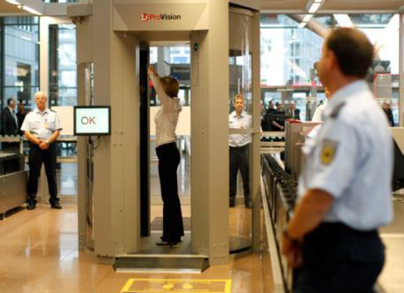
The signal available for millimeter wave imaging is substantially enhanced using active sources to illuminate the person or object, as is also the case for automotive radar. Under active illumination, images show scattering patterns from the scene, and differential contrast is due to differences in the scattering properties of clothing, skin, other dielectrics, and metals. The L3 ProVision 1 and ProVision 2 are active systems (see Figure 2.1) and are the only two AIT units currently in use at U.S. airports. The primary difference between the two units is the reduced height of the ProVision 2 (will fit areas with only 8 ft. ceilings) compared to the ProVision 1; for the purposes of this report, they are identical, including the electronics. These AIT units are image free and screen humans using active millimeter wave frequency technology operating in the 24 to 30 GHz band. They can reveal a variety of concealed objects, both metallic and nonmetallic, with automatic detection of threats.
___________________
3 The term RADAR was coined in 1940 by the United States Navy as an acronym for radio detection and ranging. The target is illuminated with a radio or microwave.
4 LIDAR measures the distance to a target by illuminating that target with a laser light. The name is an acronym for light detection and ranging.
SYSTEM DESIGN AND OPERATING PROCEDURES
The fundamental concept of operation for millimeter wave AIT scanners currently in use in the United States is to expose a subject to millimeter wavelength radiation, record the reflected radiation, then process the recorded signals to produce an image of the subject showing any suspicious objects contained in or under the subject’s clothing. The technical difficulty of implementing the concept is a consequence of the three-dimensional nature of the subject. The solution to this technical problem, as implemented in the L3 ProVision series of scanners, is to have the subject enter a “portal,” a cylinder in which the subject stands erect, with arms raised. A linear array of antennae pairs, arranged vertically as part of a “mast,” transmits (the transmit antenna of the pair) a set of millimeter wave signals, which reflect off the subject and are received by the linear array (all the receiving antennae of each pair, approximately 200 in total for each of the two arrays). These linear arrays revolve around the subject, repeatedly sending a pulse and receiving the reflection. Figure 2.2 illustrates this basic concept—a vertical linear array of

antennae (panel a) is arranged on either side of the “portal,” and the assembly revolves around the subject (panel b).
In a scan of a single subject, more than 200 vertical scan lines are produced as the ~200 transmit and ~200 receive antennae in each of the two masts are revolved through a 120 degree arc around the subject.5 Each individual transmit antenna transmits for ~6 µs during an ~8 µs pulse period.6 This transmission pattern for both linear arrays repeats approximately every 3 ms until the arrays have completed the rotation.7 As seen in the top of Figure 2.3, the pulse is on for ~6 µs and off for ~2 µs. In the middle of Figure 2.3, the time to pulse all antenna horns is ~3 ms, and this repeats until the masts have moved 120 degrees during approximately 1.3 s and produced the vertical scan lines. During the sweep, the arm accelerates initially and then decelerates toward the end of the sweep. Therefore, in order to have an evenly spaced set of measurements, the ~200 scan lines have a dynamic timing with the shortest time in between lines in the middle of the 120 degree sweep. In
___________________
5 Each antenna pair transmits and receives twice in a pattern that generates 383 spatial samples for each of the 224 scan lines of a mast, and each mast produces a set of spatial samples: one for the front and one for the back of the person scanned.
6 From Department of Health and Human Services (DHS), 2012, Compilation of Emission Safety Reports on the L3 Communications, Inc. ProVision 100 Active Millimeter Wave Advanced Imaging Technology (AIT) System, DHS/ST/TSL-12/118, Washington, D.C.
7 Presentation by Howard Bassen, Food and Drug Administration, on February 25, 2015.
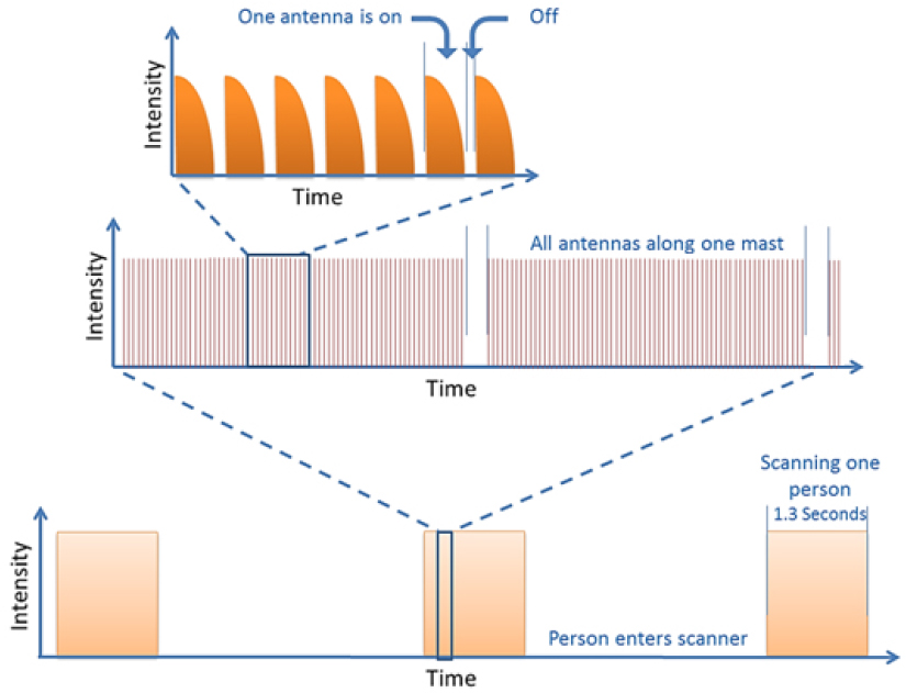
essence, this means that during the 1.3 s duration of a scan, at least one antenna is transmitting 37 percent of the time. During the remaining 63 percent of the time, there is no millimeter wave emission at all.
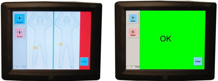
The automatic target detection (ATD) function post-processes the ~200 vertical scan lines using computer software. If threats are detected, they are displayed on the operator’s console using two iconic images of the subject, front and back. If no threat is detected, an “OK” message is displayed on the console. Figure 2.4 illustrates the operator’s console display.
In operation, subjects are instructed to enter the portal, as seen in Figure 2.1, and stand with each foot inside a template on the floor, with arms raised and hands above the head. These instructions place the subject in the center of the portal. The ProVision advanced imaging technology (AIT) scanners only require a single ~1.3 s scan of a subject in a stationary position, with no special movements or motions
required.8 The ATD software processes the data without human intervention to determine whether any threats are present. The system has an emergency stop to be used by the operator should an unexpected event occur, such as a failure of the sweep mechanism or a problem with the subject.
L3 ProVision 1 and ProVision 2 Physical Specifications
The physical specifications of the ProVision ATD and ProVision 2 system are as follows:
| Dimensions: | Height 102”/93” × diameter 77”/59” (2,594/2,360 mm × 1,956/1,500 mm) |
| Weight: | 1,800/1,500 lbs (816/681 kg) |
| Power: | ProVision ATD, 95-240 VAC/16 A, 50 to 60 Hz |
| ProVision 2, 100-240 VAC/1900 W peak, 50 to 60 Hz | |
| Operating | |
| Temperature: | ProVision ATD, 0°C to 40°C (32°F to 104°F) |
| Humidity: | 5 to 95 percent non-condensing |
| Inner Walls: | Clear Lexan 9600™ 6 mm |
| Outer Walls: | Clear Lexan 9600™ 3 mm |
| Antennas: | ~200 × 2 in two separate arrays |
| Transceiver: | GaAs monolithic microwave IC from United Monolithic Semiconductors, CHA2069-99F |
___________________
8 The duration of the active exposure during the scan is approximately 0.48 seconds.
NOTE: The transceiver has a maximum output power of 15 dBm (~30 mW)9 over the 24 to 30 GHz range.
The inner wall of the ProVision has a diameter of approximately 110 cm. There is a gap between the inner wall and the outer wall in which the two masts revolve around the subject. The distance from the mast to the inner wall is approximately 10 cm, and the distance from the mast to the center of the portal is approximately 63 cm. Therefore, in normal operation, it is not possible for a subject to stand closer than about 10 cm to the emitting horns in either of the two masts.
___________________
9 See United Monolithic Semiconductors, “CHA2069-99F/00: 18-31GHz Low Noise Amplifier,” data sheet, http://pdf1.alldatasheet.com/datasheet-pdf/view/32936/UMS/CHA2069-99F/00.html, accessed February 5, 2016.


