
7
ProVision System Design and Exposure Risk
This chapter reviews the ProVision systems design information provided by L3 Communications. The chapter begins by reviewing the procedures for installation, operation, and maintenance of the ProVision scanners. It then reviews the design of the radio frequency (RF)-power elements of the system, considering the Failure Modes and Effects Analysis provided by L3. to establish findings regarding the level of energy output at the transmitting antennae. Finally, it presents a worst-case analysis of the exposure to a screening subject resulting from both system and operator failure.
REVIEW OF PROCEDURES FOR INSTALLATION, OPERATION, AND MAINTENANCE
Installation
The information that follows regarding the installation of the L3 ProVision 2 comes from the L3 TSA PV2 Scanner Installation Manual, dated April 2015.1 No corresponding manual was available to the committee for the ProVision ATD.
The ProVision 2 scanner is delivered partially assembled in a crate to its usage site, with a second crate containing installation tools and Genie Lifts (these are utilized to safely move and position numerous heavy parts of the scanner during the
___________________
1 L3 Communications, 2015, TSA PV2 Scanner Installation Manual, Report Number 8100-20556-00, April.
assembly process). The unit is assembled on site only by authorized L3 personnel. Installation technicians must be properly trained and certified by L3—the certification is valid for 2 years following completion of the required training courses. Any violation of this will result in voiding the manufacturer warranty on the system.
Once assembled, several system checks and calibrations are required to ensure that the system operates properly and safely.
A pre-power-up check is performed to ensure that the power switch resistance is correct, followed by power-up and warm-up for at least 30 min to ensure that the electronics have reached operating temperature before scanner calibrations are performed. This is followed by Operator Control Panel (OCP) calibration.
The scanner is then calibrated by the Field Service Tool program on the desktop; this Field Service Tool is only available to specified technicians. Upon connecting to the program to the laptop, testing, diagnostics, and other buttons become active on the desktop. Using the service tool program, the technician will then place the scanner masts in “pre-cal” position, insert the calibration beam that is also used for calibration during operation, and perform an initial calibration, followed by several other calibration tests, after which the beam is removed (the masts will be moving during these tests). When these are complete, the technician will start several software tests utilizing the auto test setting on the Field Service Tool display. If the scanner fails any of these tests, the tool will help the technician troubleshoot the scanner. Several hardware tests follow the software tests, again using the Field Service Tool program. As with the software tests, the tool will help with any troubleshooting. Once these tests are successfully completed, the technician saves the settings as the scanner’s “factory baseline” and closes the auto-test window on the desktop.
The next step is for the technician to verify the data resolution of the scanner, again using the field service program only available to specified technicians. This consists of first checking that the calibration beam data set is acceptable. Following this, with the calibration beam still inside the scanner, a data quality test chart is attached to the top of the beam, to test that the scanner produces a data set of acceptable fidelity. This procedure is repeated with the test chart relocated to the center and finally to the bottom of the calibration beam. The technician then performs the Site Acceptance Test procedures in the presence of the customer. These procedures are outlined in the ProVision 2 (or ProVision ATD [where ATD stands for automatic target detection]) Site Acceptance Test Procedures Document (No. 8140-22122-00). This procedure is comprised of the following tests: functional test, system detection with OTK (Operational Test Kit) test, E-stop function/lockdown mode test, operator display test, UPS (uninterruptible power supply) test, fault reset, FDRS (Field Data Reporting System) test, power down test, and configuration audit. The results of these tests are documented in the Site Acceptance Test Report, and the scanner is ready for operation.
Finding 7.1: The installation procedure leaves the ProVision system in a normal operating condition in which both the RF and mechanical systems are operating as designed.
OPERATION OF THE L3 PROVISION ATD AND THE L3 PROVISION 2 SCANNERS
The information that follows regarding the operation of the L3 ProVision 2 comes from TSA PV2 Scanner Operator Manual, dated April 2015.2 A corresponding manual, TSA PV1 Scanner Operator Manual, dated September 2014,3 was available to the committee for the ProVision ATD. Review of that document uncovered several hardware and software design differences, none of which should affect the operation of any of the versions of the scanners. Therefore, the information for the ProVision 2 applies to operation of the ProVision ATD model for the purposes of the committee’s review. Additionally, four hazard warning labels are located prominently on the scanner regarding hazardous voltage, high current, and moving parts safety.
The UPS includes a backup battery, which provides emergency power if necessary; the UPS has a power cord that is connected to a junction box to access this emergency power source. The UPS is plugged into facility power. The scanner is plugged into a receptacle on the UPS. If facility power is interrupted, the UPS will disable the scanning process and provide backup power to commence an orderly shutdown of the Advanced System Control Unit (ASCU), notifying the operator via the Operator Control Panel (OCP), a touch-sensitive screen attached to the scanner. If the UPS battery degrades, the UPS will start the same shutdown process and indicate so on the OCP.
The scanner can only be operated by trained Transportation Security Administration (TSA) personnel who are in possession of a password that starts operation after being entered into the OCP screen. The operator interfaces, consisting of the OCP, two sets of on/off switches (one set on the UPS) and an emergency stop switch, are all logically positioned and easy to use.
During operation of the scanner, the passenger’s body is never displayed; instead, it is represented on the OCP by a software-generated gender-neutral mannequin image. The scanner is operated using only the OCP. Apart from the
___________________
2 L3 Communications, 2015, TSA PV2 Scanner Operator Manual, Software Version 3.20, Report Number 8100-20601-OM, Rev A5, April.
3 L3 Communications, 2014, TSA PV1 Scanner Operator Manual, Software Version 3.20, Report Number 8100-20601-OM, Rev A4, September.
on/off switches, the scanner has no manual controls—it can be operated using the OCP only.
At the start of a shift, the operator first must bring the scanner online. During this process, as during passenger scanning and calibration, any system malfunctions will be displayed on the OCP, including what the operator must do to correct (or further investigate) them. The first step is to ensure that the emergency stop switch is not pressed in. The scanner is then turned on using the power switch, the OCP powers up, and the display appears on the screen after a few minutes of warm-up. After warm-up, the operator logs in to the scanner with a user ID and password. A TSA disclaimer then appears. The operator presses “OK,” and the FDRS screen appears. The only functions available are “Scan,”“OTK,” and “Logoff.” The operator presses “Scan” to access the operations screen.
The operations screen is now in calibration mode—the calibration process will start once the “calibration” button is pressed. Once this button is pressed, a dialog box opens, asking whether the scanner is empty. Once verified, the operator presses the OK button to proceed. The scanner then begins a mast motion calibration, which lasts about 45 s; when complete, a “motion calibrated” alert appears. The operator then presses a “reset” button to clear that message and presses the “calibration” button again to start the clutter calibration process. This clutter calibration process is required throughout the day—typically every 30 min of continuous usage. It is also recommended that a calibration be conducted at the start of each shift. At the end of this process, the operator verifies that there is no red wrench icon on the screen—which is displayed near the calibration button when the scanner detects a change in the electronic circuity that could compromise the system’s performance. This test is performed as part of every clutter calibration. If the red wrench icon appears, the operator presses the “reset” button to see whether the icon disappears. If it does not, the operator presses the “calibrate” button again. If, after calibrating, the red wrench icon still does not disappear and the Functional Isolation Test (FIT) button appears, the operator will press that button and perform the FIT process. If the FIT button does not appear, the operator shuts down the scanner, waits 15 to 20 s, powers up the scanner, and performs another calibration. If the red wrench icon still appears, the operator contacts L3 customer support.
At this point, if no red wrench icon appears, the operator presses the menu button to return to the FDRS screen. The operator then presses the OTK button to initiate the OTK process. If there is a system fault, the “reset error” button on that screen will be active, with an accompanying description of any faults—which must be manually cleared before the OTK process can proceed by clicking the “reset error” button. The operator clicks on “start test” and a clutter calibration process begins. If the clutter calibration passes, the screen instructs the operator to insert a calibration beam (supplied with the scanner) into the scanner. The beam is scanned after it is inserted; if that process passes, the screen instructs the operator to place
an image quality chart target on the beam and to scan again. If this scan passes, the OTK process is complete. If any of these scans fail, the screen will instruct the operator on next steps, which could include repeating that step, shutting down and restarting the scanner, or calling L3 customer support if faults are not cleared. Only after the OTK operations are carried out without any displayed alert or warning is the scanner ready to begin scanning passengers; the operator is instructed to allow no passengers inside until this process is completed.
The passenger scanning process consists of the following steps:
- Instruct the passenger to enter the scanner.
- Instruct the passenger to position his/her feet on the scanner floor decals.
- Instruct the passenger to assume the “hands-up” position, as illustrated on the radome window in front of him/her.
- Instruct the passenger to remain completely still for 3 s while the scan is under way.
- The operator then presses a gender-specific button on the display to start the scan.4 The masts start moving, and after about 7 s, the results of the scan are displayed on the OCP.
- When the scan is complete, the operator asks the passenger to exit the scanner to wait for the scan results.
- If no potential threats (possible objects) are detected, the OCP screen is green with the message “CLEAR” in the center.
- If the operator is satisfied that the passenger is secure, the passenger is given the go-ahead to leave the area. The operator then presses the Next button to clear the screen and start the next scan.
- When one or more potential threats are detected, the OCP screen shows their location using a gender-neutral mannequin to represent the passenger—there are two separate frames showing the front and back of the passenger. The screen also displays a thick red stripe down the right side of screen. The location of the object or objects is displayed as red-bordered yellow indicator areas on the mannequin. The operators ask the passenger to exit the scanner and follow TSA Standard Operating Procedures while further addressing the passenger to investigate the potential threats. To keep the passenger queue going, the scanner has a feature that allows the operator to scan the next passenger while the first one is still being addressed by another transportation security officer.
___________________
4 Note that the scan with millimeter waves is identical in both gender cases; only the post software processing is different, so the safety of using the portal is not affected.
A “SCANNER MALFUNCTION—CALL SERVICE TECHNICIAN” message may appear in the center of a mostly orange screen. This indicates that there has been an equipment malfunction. If this appears, the operator presses the Next button to log off and back on to see whether the problem has cleared. If the problem has not cleared, the operator presses the Reset button. If the FIT button appears, the operator runs the FIT process to further explore the problem. If not, the operator logs off of the system and calls L3 customer support. To run the FIT process, the operator presses the FIT button, and then the OK button if a Start Isolation Test dialog box appears. After the FIT test is complete, a FIT screen appears, displaying the suspected component(s). The operator makes a note of the component(s) in question, and presses the Continue button to power off the system. When the screen goes dark, the operator flips the power control to the off (O) position and calls L3 customer support.
If necessary, the operator can shut down the scanner almost instantly by pressing the emergency stop (E-stop) control, which is mounted below the OCP mounting bracket.
If a problem occurs during operation of the scanner, an Alert message appears on the OCP. Warning and information messages may appear as well.
The standard procedure for most Alert messages is to press the Reset button and wait to see whether the software can solve the problem. If that does not work and the FIT button appears, the operator runs the FIT process, as described in an earlier paragraph. Otherwise, the operator reboots the system; if the problem persists, the operator shuts down the system and calls L3 customer support.
There are, however, some Critical Alert messages. If any of these appear, the operator must take the scanner immediately out of service and have it inspected by a technician. The following Critical Alert messages may indicate mechanical interference between the moving parts:
- Pre-sweep drift detected in CW home sensor,
- Post-sweep drift detected in CW home sensor,
- Pre-sweep drift detected in CCW home sensor,
- Post-sweep drift detected in CCW home sensor, and
- SCU ALERT:32008: System malfunction.
A Warning message gives the operator a maintenance operation to carry out, or it informs the operator of something in progress, such as a motor calibration. In some cases, no action is required; in others, the operator can press the Reset button to clear the problem.
Information messages inform the operator of current conditions and may suggest actions to take. While these messages do not indicate an alert, their content should be noted and acted upon as the situation requires.
Finding 7.2: ProVision self-diagnostics will detect failures that occur during operation of a sweep, requiring the operator to either allow the system to self re-calibrate or take the system offline.
MAINTENANCE OF THE L3 PROVISION ATD AND THE L3 PROVISION 2 SCANNERS
The information that follows regarding the maintenance of the L3 ProVision 2 comes from L3 report Number 8100-20602-TM, Rev A0, TSA PV2 Scanner Maintenance Manual, dated April 2015. A corresponding manual, L3 report Number 8100-12052-TM, Rev B4, TSA PV1 Scanner Technical Manual, dated March 2013, was available to the committee for the ProVision ATD. Review of the manuals for both the ProVision ATD and ProVision 2 uncovered several hardware and software design differences, none of which should affect operation or safety. Although maintenance may differ, depending on the hardware and software differences between models, the committee does not expect these differences to affect safe operation of the scanner. Significant hardware and software differences will be highlighted in the discussion that follows.
For the ProVision 2, the general description on pages 20 through 28 includes diagrams of the following: mainframe assembly, antenna frame assembly, electrical enclosure, upper frame assembly, and operator control panel. The technical description on pages 30 through 32 includes the following topics, plus functional diagrams for each and system interconnect diagrams, are all located in an appendix: power distribution, detection, and motor control.
The ProVision ATD and ProVision 2 scanners are specifically designed to prevent injury during system operation and maintenance. Injury can be avoided by knowing the following safety features:
-
Emergency stop switch. The red and yellow E-stop switch, located just below the OCP mounting point, disables the motor and associated moving parts, such as the antenna masts, swing arm, and belt drive. In case of emergency, the operator does the following:
- Press the E-stop switch to disable the moving parts.
- Turn the red button a quarter turn clockwise to reset the E-stop control.
-
Electrical power control. The scanner’s power switch removes all electrical power from the scanner. In case of an electrical emergency, the operator does the following:
- Press the bottom portion (O) of the scanner’s power control to remove all power from the scanner.
- Turn off the UPS power and unplug the scanner’s power cord from the UPS.
During maintenance, to clear a trapped object or person from the belt or swing arm, the operator can manually move the swing arm as follows:
- Remove the motor cover.
- Verify that the system is plugged in and turn the system on.
- Connect the motor brake release jumper to move the brake release cable and listen for the motor release solenoid to produce a clicking sound.
- Reset the E-stop switch by turning the red button a quarter turn clockwise.
- Then, carefully move the swing arm by hand to clear any object or person.
During non-maintenance normal operating conditions, the arms are fully enclosed and cannot be accessed. In addition, as mentioned earlier in the discussion of the operator manual, safety labels regarding hazardous voltage and high current and moving equipment are positioned prominently on the scanner.
QUARTERLY AND SEMI-ANNUAL PREVENTATIVE MAINTENANCE INSPECTION/MAINTENANCE TASKS
The ProVision 2 and ProVision ATD manuals list several tasks that must be performed on a quarterly basis (every 3 months). These include the following:
- Inspect and clean the mast and mast area (including radome panels).
- Inspect and clean the interior area (portal area for ProVision ATD).
- Clean the external surfaces.
- Inspect and clean the Operator Control Panel (OCP) monitor.
- Inspect and clean the Advanced System Control Unit (ASCU).
- Inspect and clean the Image Sampling Units (ISUs).
- Inspect and clean the electrical enclosure (ProVision 2 only).
- Components are:
- 24V/48V DC power supply
- Motor controller
- Power distribution board
- RFI filter, relay and metal oxide varistor (MOV)
- Components are:
- Inspect and clean the Control Tower (ProVision ATD only).
- Components are:
- 24V/48V DC power supply
- Motor controller
- Power distribution board
- RFI filter, relay and metal oxide varistor (MOV)
- E-stop switch
- Power on/off switch
- Components are:
-
- AC line filter
- Power dissipation module
- Check the motor collar torque.
- Check operation of the equipment fans.
- Perform the system power turn-on/fault isolation procedures.
- Perform an OCP calibration.
- Perform open/closed calibrations.
- Create a new baseline for the system.
- Perform software tests.
- Perform hardware tests.
- Perform the Operational Test Kit (OTK).
- Check frame alignment (ProVision ATD only).
- Inspect and clean the Uninterruptable Power Supply (UPS) (ProVision ATD only).
- Download the resulting Field Service Reporting System (FSRS) reports after completion of these tests.
The ProVision 2 and ProVision ATD manuals list several tasks that must be performed on a semi-annual basis (every 6 months). These include the following:
- Perform quarterly inspection/maintenance described above.
- Inspect the cable chain and drive springs (ProVision ATD only).
- Inspect the drive motor.
- Inspect the drive belt.
A chapter in the ProVision 2 Maintenance Manual provides the recommended troubleshooting process, including a system fault logic tree to guide the user to additional resources to isolate a system fault to the faulty component (page 52 of the manual). The logic tree includes the following:
- Perform system turn-on fault isolation procedure (with numerous OCP fault code descriptions).
- Perform system auto test procedures for software and hardware, including the mast/antenna and single antenna.
- Perform debug test procedures.
- Perform detection performance analysis procedures.
Several corrective maintenance procedures are required to maintain the ProVision 2 scanner in operating condition. For hardware, these include the following:
- Lock out/tag out procedures.
- Removal and installation procedures for the following components:
- Ceiling access cover
- Floor side panel
- Floor center panel
- LED fixture
- Inner radome panel movement
- Mast components, including transceiver, breakout board, TX/RX manifold switch, receive antenna switch, and transmit antenna switch
- E-stop switch and main switch/power input
- Electrical enclosure components, including 24V/48V DC power supply, aries motor controller, and power distribution board
- Upper frame components, including the ASCU, ISU, home sensor circuit card assembly, drive belt, motor, braking resistor, power strip and bracket assembly, and magnetic encoder and cable
- OCP touchscreen monitor and power cord
- Universal Power Supply (UPS)
- Removal and installation procedures for the calibration beam.
For software, these include the following:
- ASCU computer procedures
- ASCU name change
- ASCU password change
- ASCU time change
- System software installation
A chapter in the ProVision ATD Maintenance Manual provides the recommended troubleshooting process, including a system fault logic tree to guide the user to additional resources to isolate a system fault to the faulty component (page 54 of the manual). The logic tree includes the following:
- Perform system turn-on fault isolation procedure (with numerous OCP fault code descriptions).
- Perform system auto test procedures for software and hardware, including the mast/antenna and single antenna.
- Perform debug test procedures.
- Perform detection performance analysis procedures.
Several corrective maintenance procedures are required to maintain the ProVision ATD scanner in operating condition. For hardware, these include the following:
- Lock out/tag out procedures.
- Removal and installation procedures for the following components:
- Outer radome panel
- Ceiling access cover
- Floor side panel
- Floor center panel
- LED fixture
- Inner radome panel movement
- Mast components, including transceiver, VC adapter, breakout board, TX/RX manifold switch, receive antenna switch, and transmit antenna switch
- Control tower components, including 24V/48V DC power supply, GV6 motor controller, Gemini power dissipation module, power distribution board, E-stop switch and main switch/power input, and input power RFI filter, relay and MOV
- Upper frame components, including the ASCU, ISU, home sensor circuit card assembly, drive belt, motor, braking resistor, power strip and bracket assembly, and magnetic encoder and cable
- OCP touchscreen monitor and power cord
- Universal Power Supply (UPS)
- Removal and installation procedures for the calibration beam.
For Software Version 3.8.20, these include the following:
- ASCU II computer software installation procedures
- Computer name change
- Password change
- Time change
- FDRS application software installation on the ASCU
- ATD operating software installation on the ASCU
- No zone INI installation on the ASCU
- Running of the software scripts on the ASCU
- OS hardening on the ASCU
- ASCU III computer software installation procedures
- Running of the software scripts on the ASCU
- Computer name, date/time and password change
- FDRS application software installation on the ASCU
- Scout operating software installation on the ASCU
- No zone INI installation on the ASCU
- FDRS firewall rules
- Network configuration verification
The manual describes several steps necessary to install this version of the ASCU III software. Additionally, the “Part Restoration” section below outlines what is assumed to be all ASCU and software versions of the ProVision scanner: FDRS Setup and GV6 software installation.
Part Restoration
Part Restoration is a last resort method to restore the ASCU to a freshly imaged computer. As such, Part Restoration should be used when no other methods to fix a problem work. The manual describes the process for software Version 3.8.20 for both ASCU IIs and ASCU IIIs and for software Version 3.8.31 for ASCU IIIs.
Finally, the ProVision 2 and ProVision ATD maintenance manuals also contain a comprehensive illustrated parts list for the scanners.
Summary
Each manual contains an excellent general description of the scanner, followed by an excellent technical description of its operation.
The ProVision ATD and ProVision 2 scanners are specifically designed to prevent injury during system operations or maintenance. Injury can be avoided by knowing the following safety features:
- Emergency stop switch: The red and yellow E-stop switch, located just below the OCP mounting point, disables the motor and associated moving parts, such as the antenna masts, swing arm, and belt drive.
- Electrical power control: The scanner’s power control removes all electrical power from the scanner.
To clear a trapped object or person from the belt or swing arm during maintenance, the operator can manually move the swing arm as follows (during normal operation the arms are fully enclosed):
- Remove the motor cover.
- Verify that the system is plugged in and turn the system on.
- Connect the motor brake release jumper to move the brake release cable and listen for the motor release solenoid to produce a clicking sound.
- Reset the E-stop switch by turning the red button a quarter turn clockwise.
- Then, carefully move the swing arm by hand to clear any object or person.
As mentioned earlier in the discussion of the operator manual, safety labels regarding hazardous voltage and high current and moving equipment are positioned prominently on the scanner.
The ProVision 2 and ProVision ATD manuals list several tasks that must be performed on a quarterly basis (every 3 months). These include the following:
- Inspect and clean the mast and mast area (including radome panels).
- Inspect and clean the interior area (portal area for ProVision ATD).
- Clean the external surfaces.
- Inspect and clean the Operator Control Panel (OCP) monitor.
- Inspect and clean the Advanced System Control Unit (ASCU).
- Inspect and clean the Image Sampling Units (ISUs).
- Inspect and clean the electrical enclosure (ProVision 2 only).
- Inspect and clean the Control Tower (ProVision ATD only).
- Check the motor collar torque.
- Check operation of the equipment fans.
- Perform the system power turn-on/fault isolation procedures.
- Perform an OCP calibration.
- Perform open/closed calibrations.
- Create a new baseline for the system.
- Perform software tests.
- Perform hardware tests.
- Perform the Operational Test Kit (OTK).
- Check frame alignment (ProVision ATD only).
- Inspect and clean the Uninterruptable Power Supply (UPS) (ProVision ATD only).
- Download the resulting Field Service Reporting System (FSRS) reports after completion of these tests.
The ProVision 2 and ProVision ATD manuals list several tasks that must be performed on a semi-annual basis (every 6 months). These include the following:
- Perform quarterly inspection/maintenance described above.
- Inspect the cable chain and drive springs (ProVision ATD only).
- Inspect the drive motor.
- Inspect the drive belt.
A chapter in the ProVision 2 Maintenance Manual provides the recommended troubleshooting process, including a system fault logic tree to guide the user to additional resources to isolate a system fault to the faulty component.
Several corrective maintenance procedures are required to maintain the ProVision 2 scanner in operating condition. For hardware, these include the following:
- Lock out/tag out procedures.
- Removal and installation procedures for the following components:
- Ceiling access cover
- Floor side panel
- Floor center panel
- LED fixture
- Inner radome panel movement
- Mast components, including transceiver, breakout board, TX/RX manifold switch, receive antenna switch, and transmit antenna switch
- E-stop switch and main switch/power input
- Electrical enclosure components, including 24V/48V DC power supply, aries motor controller, and power distribution board
- Upper frame components, including the ASCU, ISU, home sensor circuit card assembly, drive belt, motor, braking resistor, power strip and bracket assembly, and magnetic encoder and cable
- OCP touchscreen monitor and power cord
- Universal Power Supply (UPS)
- Removal and installation procedures for the calibration beam.
For software, these include ASCU computer procedures.
A chapter in the ProVision ATD Maintenance Manual provides the recommended troubleshooting process, including a system fault logic tree to guide the user to additional resources to isolate a system fault to the faulty component.
Several corrective maintenance procedures are required to maintain the ProVision ATD scanner in operating condition.
For hardware, these include the following:
- Lock out/tag out procedures.
- Removal and installation procedures for the following components:
- Outer radome panel
- Ceiling access cover
- Floor side panel
- Floor center panel
- LED fixture
- Inner radome panel movement
- Mast components, including transceiver, VC adapter, breakout board, TX/RX manifold switch, receive antenna switch, and transmit antenna switch
-
- Control tower components, including 24V/48V DC power supply, GV6 motor controller, Gemini power dissipation module, power distribution board, E-stop switch and main switch/power input, and input power RFI filter, relay and MOV
- Upper frame components, including the ASCU, ISU, home sensor circuit card assembly, drive belt, motor, braking resistor, power strip and bracket assembly, and magnetic encoder and cable
- OCP touchscreen monitor and power cord
- Universal Power Supply (UPS)
- Removal and installation procedures for the calibration beam.
For software, these include the following:
- Software Version 3.8.20 ASCU II or ASCU III is to be installed depending on which computer is installed on the scanner.
- Software Version 3.8.31 is to be installed only on systems with V2ISUs (Image Sampling Units) and ASCU III computers. Do not install on systems with the original ISUs. The manual describes several steps necessary to install this version of the ASCU III software.
Part Restoration is a last resort method to restore the ASCU to a freshly imaged computer. As such, Part Restoration should be used when no other methods to fix a problem work. The manual describes the process for software version 3.8.20 for both ASCU IIs and ASCU IIIs and for software version 3.8.31 for ASCU IIIs.
Finally, the ProVision 2 and ProVision ATD maintenance manuals also contain a comprehensive illustrated parts list for the scanners.
Finding 7.3: Maintenance of the ProVision systems returns the system to its nominal operating condition.
The installation and maintenance of the ProVision systems leave them in a nominal operating condition. In operation, these systems require no technical expertise for calibration, because they incorporate continuous self-diagnostics. The standard operating procedures would not permit a malfunctioning system to be used for more than the single scan in which the malfunction occurred. Relevant to the charge of the committee, the main concern regarding design, maintenance, and operation is the possibility of malfunction during a single scan that would result in exposure beyond the recommended limits. That concern is addressed by the following two sections.
Finding 7.4: Practically all potential malfunctions of the ProVision ATD and ProVision 2 are caught during the cycle of scanning just one individual.
REVIEW OF PROVISION SYSTEMS DESIGN
Power Output
The committee had access to very limited information about the exact technical details and design of the ProVision AIT such as circuit diagrams and full electrical schematics, aside from the general transceiver and the basic architecture of the system. However, enough knowledge of the details has been gained to assess the overall safety with respect to RF radiation in the 24 to 30 GHz range. Each mast in the ProVision has a dedicated system for generating and transmitting the millimeter wave pulses, and for receiving and accumulating the data from the detected signals. The transceiver employed is based on a GaAs monolithic microwave IC from United Monolithic Semiconductors, the CHA2069-99F. This device, over the 24 to 30 GHz range, has a maximum output power of 15 dBm (~30 mW).5
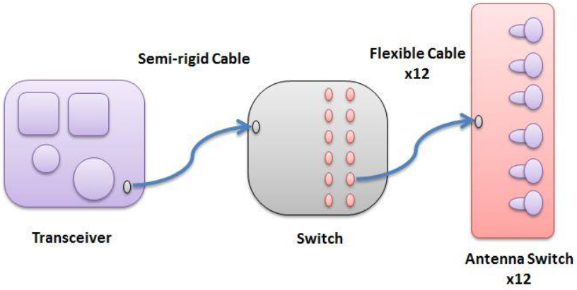
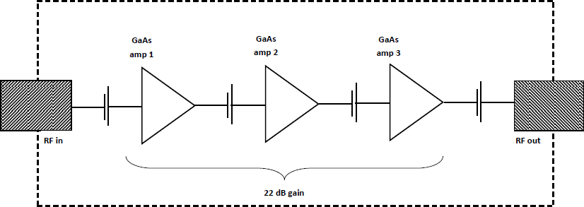
To look at possible malfunctions that would expose an individual to power density higher than the limit of 10 W/m2 one would start with the final amplifier in the transceiver generating the signal as seen in Figure 7.1. Per the specification, attempts to drive the device (see Figure 7.2) above 15 dBm for more than 1 s “may cause permanent damage”6 to the device, and the current transceiver design has the output amplifier operating in full saturation. The signal path for the system after the final output amplifier is a semi-rigid cable connecting to a manifold switch that in turn connects 12 different antenna switch modules with flexible cables. These 12 modules are located in one of the arms of the ProVision. From the final amplifier, it is possible to follow the signal path and analyze what can happen to the signal power density as a result of natural losses.
Following the signal path, one can conclude that any damage or fault in the cables and switches cannot suddenly cause their signal losses to become less than during normal operation. Bending or pinching of the cables would introduce more losses, and degradation of the connectors (oxidation of surfaces, incorrect torqueing) would also introduce increased losses. The semi-rigid cable for the ProVision in Figure 7.1 is more than 40 in. in length, and the flex cables are a few inches in length. The total cable losses, together with the manifold and antenna switch
___________________
5 See United Monolithic Semiconductors, Part CHA2069-99F/00 datasheet for the 18-31 GHz Low Noise Amplifier: GaAs Monolithic Microwave IC, Ref. DSCHA20699273-8-Sep-99, http://pdf1.alldatasheet.com/datasheet-pdf/view/32936/UMS/CHA2069-99F/00.html, accessed February 5, 2016.
6 Ibid., p. 2.
module losses, are typically near 30 dB.7 The signal path losses combined with the saturated transceiver signal means that the power fed to the antenna horn is in the order of 0.00003 W.
Finding 7.5: Maximum power output of the ProVision transceiver is 0.032 W, and signal losses from the transceiver to the antennae are significant (in the range of 25 dB to 40 dB) and will not be decreased by system use or damage to the passive elements (cables and switches).
FAILURE MODES
Engineers often determine the performance and safety of complex systems by performing a Failure Modes and Effects Analysis (FMEA), or Failure Modes, Effects and Criticality Analysis (FMECA). The following is a brief description of these types of analyses and their purpose.8
FMEA and FMECA are both methodologies designed to identify potential failure modes for a product or process and are used to assess the risk associated with
___________________
7 The losses for a system like this can vary quite a lot. It is estimated that losses can range from 25 dB to 40 dB.
8 See Reliability Hotwire, Issue 46, December 2004, http://www.weibull.com/hotwire/issue46/.
those failure modes, to rank the issues in terms of importance, and to identify and carry out corrective actions to address the most serious concerns.
Although the purpose, terminology, and other details can vary according to type (e.g., Process FMEA-PFMEA, Design FMEA-DFMEA, System FMEA, Product FMEA, FMECA, etc.), the basic methodology is similar for all.
In general, FMEA/FMECA requires the identification of the following basic information:9
- Item(s)
- Function(s)
- Failure(s)
- Effect(s) of Failure
- Cause(s) of Failure
- Current Control(s)
- Recommended Action(s)
- Plus other relevant details
Most analyses of this type also include some method to assess the risk associated with the issues identified during the analysis and to prioritize corrective actions. Two common methods include Risk Priority Numbers (RPNs) and Criticality Analysis (FMEA with Criticality Analysis = FMECA).
There are many published guidelines and standards for the conduct and recommended reporting format of FMEAs and FMECAs. Some of the main pub-
___________________
9 ReliaSoft Corporation, “Failure Mode and Effect Analysis (FMEA) and Failure Modes, Effects and Criticality Analysis (FMECA),” http://www.weibull.com/basics/fmea.htm?, accessed May 8, 2016.
lished standards for this type of analysis include SAE J1739,10 AIAG FMEA-4,11 and MIL-STD-1629A.12 In addition, many industries and companies have developed their own procedures to meet the specific requirements of their products/processes.13
The conduct of a FMEA or FMECA gives the designers insight into the possible failure modes of complex machines such as the ProVision ATD and ProVision 2 scanners and thus valuable insight into any potential safety issues. However, in the material received by the committee from TSA, no formal FMEA existed in the traditional sense, but upon request, the manufacturer, L3 Technologies (formerly L-3 Communications Holdings), provided a table describing some of the subsystems, as discussed in the next section.
Finding 7.6: It appears that no Failure Mode and Effects Analysis following established procedures was conducted while the ProVision millimeter wave AIT portals were designed and manufactured.
Recommendation 7.1: The Transportation Security Administration should require Failure Mode and Effects Analysis following established procedures to be done on any complex systems it plans to put into operation.
HAZARD FROM COMPONENT FAILURE
At the request of the committee, L3 provided a partial FMEA for the portion of the RF subsystem from the transceiver to the transmit antennae (failures in other parts of the RF system would not increase the subject’s exposure to RF energy).
Below is the Antenna Mast Component Description, Device Detail, Failure Mode, Mechanism, Failure Causes, Local Effects, and System Effects, as provided to the committee.
Transceiver Module:
- Output power amplifier. This is the last amplification stage in the TX path.
- Failure Mode—Amplifier integrated circuit failure
___________________
10 See SAE International, Standard J1739_200901, revised January 15, 2009, http://standards.sae.org/j1739_200901/.
11 See Automotive Industry Action Group, “Potential Failure Mode and Effects Analysis,” FMEA-4, June 2008, http://www.aiag.org/store/publications.
12 See Department of Defense, “Procedure for Performing a Failure Mode, Effects and Criticality,” Military Standard MIL-STD-1629A, issued November 24, 1980, cancelled in August 1994.
13 ReliaSoft Corporation, “Failure Mode and Effect Analysis (FMEA) and Failure Modes, Effects and Criticality Analysis (FMECA),” http://www.weibull.com/basics/fmea.htm?, accessed May 8, 2016.
-
- Mechanism—Integrated circuit element short or open results in loss of RF gain in the amplifier, which in turn reduces power delivered to the load
- Failure Causes—Electrostatic-discharge (ESD) damage due to latent manufacturing defects
- Local Effects—Reduction in output gain and output power
- System Effects—Reduced TX output power on all antenna elements*
- Output amplifier input source (overdrive failure)
- Failure Mode—Overdrive of RF input into transceiver output amplifier
- Mechanism—No known mechanism for increased drive level. There is no software control of maximum power level in transmit signal path.
- Failure Causes—None listed
- Local Effects—The output amplifier is operating in saturation, which limits the maximum power out of the device. There are no further amplification stages in the TX path.
- System Effects—TX output power would not increase above the normal operating level.
- Output amplifier input source (no pulse failure)
- Failure Mode—Pulse modulator control circuit malfunctions in a stuck “ON” condition.
- Mechanism—The modulator control circuit turns off the TX signal input to the final output amplifier.
- Failure Causes—Compromised cable connection for control signal for the output modulator.
- Local Effects—The TX signal would be active during the switching time between antennas.
- System Effects—Peak TX output power level would be the same as in normal operation.*
- Output port coaxial connector
- Failure Mode—Compromised connection on the semi-rigid cable
- Mechanism—Loose or damaged connection
- Failure Causes—Improper torque or assembly of precision connector
- Local Effects—Increased loss and high reflection coefficient at the connection point reduces the power delivered to the manifold switch
- System Effects—Reduced TX output over all antenna elements on the antenna mast*
Transceiver to Manifold Switch Connection:
- Semi-rigid coaxial cable
- Failure Mode—Mechanical damage to cable
- Mechanism—Crimping or crushing of semi-rigid cable
- Failure Causes—Incorrect mechanical retention in mast assembly or field service process
- Local Effects—Cable discontinuity will induce a signal reflection. High VSWR in cable, which reduces the power delivered to the switch antenna module
- System Effects—Reduced TX output on all antenna elements*
Manifold Switch Module:
- Input coaxial cable port connector
- Failure Mode—Compromised connection on coaxial input cable from the transceiver
- Mechanism—Loose or damaged connection
- Failure Causes—Improper torque or assembly of precision connector
- Local Effects—Increased loss and high reflection coefficient at the connection point reduced the power delivered to the manifold switch
- System Effects—Reduced output power on all manifold ports and corresponding downstream antenna ports*
- Monolithic Microwave Integrated Circuit (MMIC)**
- Failure Mode—Switch integrated circuit failure
- Mechanism—Integrated circuit switching element open or short failure
- Failure Causes—ESD damage due to latent manufacturing defect
- Local Effects—Increased switch insertion loss due to load sharing and/or mismatch internal to the integrated circuit
- System Effects—Reduced TX output on one or more antenna modules*
- Power and control cable to manifold switch
- Failure Mode—Compromised connection of power and control signal ribbon cable
- Mechanism—Loose or damaged connection
- Failure Causes—Improper seating and engagement of locking feature
- Local Effects—Power loss to switch module resulting in significant increase signal path attenuation
- System Effects—Significantly reduced TX output*
- Manifold switch control circuitry
- Failure Mode—Damaged control circuit
-
- Mechanism—MMIC switch control signals compromised, stuck on single port or selected out of sequence
- Failure Causes—ESD damage, physical damage to components
- Local Effects—Incorrect switch port selection will result in RF power being misdirected in the signal path
- System Effects—Reduced TX output on many antenna ports*
- Output port coaxial connector
- Failure Mode—Compromised connection on the output port coaxial connector
- Mechanism—Loose or damaged connection
- Failure Causes—Improper torque or assembly of precision connector
- Local Effects—Increased loss and high reflection coefficient at the connection point reduced the power delivered to the antenna switch
- System Effects—Reduced TX output to one of the antenna modules*
Manifold Switch to Antenna Connection (x12):
- Flexible coaxial cable
- Failure Mode—Mechanical damage to cable
- Mechanism—Crimping or crushing of flexible cable
- Failure Causes—Incorrect mechanical retention in mast assembly or field service process
- Local Effects—Cable discontinuity will induce a signal reflection. High voltage standing wave ratio (VSWR) in cable will reduce the power delivered to the switch antenna module
- System Effects—Reduced TX output on a single antenna module*
Antenna Module (x12):
- Input port coaxial connector
- Failure Mode—Compromised connection on input signal coax
- Mechanism—Loose or damaged connection
- Failure Causes—Improper torque or assembly of coax connector
- Local Effects—Increased loss and high reflection coefficient at the connection point reducing the power delivered to the antenna switch
- System Effects—Reduced TX output to all antenna elements on the module*
- Custom module with coaxial input and integrated antenna element outputs.**
- Failure Mode—Switch integrated circuit failure
- Mechanism—Integrated circuit switching element open or short failure
-
- Failure Causes—ESD damage due to latent manufacturing defects
- Local Effects—Increased switch insertion loss due to load sharing and/or mismatch internal to the integrated circuit
- System Effects—Reduced TX output on one or more antenna elements*
- Power and control cable to manifold switch
- Failure Mode—Compromised connection of power and control signal ribbon cable.
- Mechanism—Loose or damaged connection
- Failure Causes—Improper seating and engagement of locking feature
- Local Effects—Power loss to switch module resulting in significant increase in attenuation of the signal path
- System Effects—Greatly reduced TX output*
- Antenna switch control circuitry
- Failure Mode—Damaged control circuit
- Mechanism—Switch integrated circuit control signals compromised, stuck on single port selected out of sequence
- Failure Causes—ESD damage, physical damage to components
- Local Effects—Incorrect switch port selection will result in RF power being mis-directed in the signal path
- System Effects—No TX output on many antenna ports*
- Antenna element
- Failure Mode—Compromised antenna feed structure
- Mechanism—physical damage or wire bond failure due to latent manufacturing defect
- Failure Causes—Antenna launch circuit or connection compromised
- Local Effects—Loss of RF signal path to a single antenna element
- System Effects—RF output degradation on a single element*
* Detectable degradation in system self-test.
** MMIC switch components are the only active devices in the signal path.
L3 identified 16 failure modes. In 14 of the failure modes, the transmit power output to the antennae would decrease, and this degradation would be detected by system self-diagnostics; these failure modes are “safe” with respect to exposure hazard. One failure mode (output amplifier input source) is associated with overdrive of RF input to the output amplifier, which “would not increase” the power output. In fact, per the transceiver device specifications, overdriving for more than 1 s would likely cause the device to fail; this also is a “safe” failure mode. Only one
failure mode is of further concern (antenna switch control circuitry), because it admits the possibility that the transmitted signal is not switched between the ~200 transmit antennae, but continues to be transmitted from one single horn, and there is no indication that a self-diagnostic test would detect this failure. (There may be such a test, but it was not described in material available to the committee.)
There are two scenarios of concern: (1) if the mechanical subsystem has not failed, this single horn would transmit all pulses during the 120-degree sweep of the mast; and (2) if the mechanical subsystem has failed, this single horn would transmit all pulses from a single location for the portion of the sweep cycle remaining after the failure occurred. Regarding hazard, the difference in these two scenarios is not significant, because the recommended limit of 10 W/m2 applies whether the incident area is constant or changing.
No FMEA for the mechanical subsystem was provided by L3. In the mechanical subsystem, however, there are two safety-related elements. First, an optical encoder provides feedback to the motor controller on the position of the masts. Differences between the intended and detected positions signal a motion error, which stops the scan. Good design practice would be for the detection of a motion error to cause the transmitter to shut down. However, without detailed design specifications, or an original equipment manufacturer-supplied FEMA, it is not possible to comment on this aspect of design. The units also incorporate an E-stop at the operator console, so that if the swing arm should stop mid-scan, the operator can shut down the system.
Finding 7.7: The mechanical subsystem of the ProVision does not affect the dose delivered during failure scenarios involving the scanner arms stopping or the antenna switch failing.
WORST-CASE ANALYSIS OF EXPOSURE
This extreme analysis addresses the question, “If the system fails, what is the absolute worst-case exposure of RF energy to the subject pushing all calculations to an extreme?” The floor of these units has two footprint decals, and the operator instructs the subject to stand with feet on the decals and raise hands over head.14 This is intended to position the subject in the center of the portal. To appreciate the distance from the subject to the masts, consider the 95th percentile 40-year-old American male15 who has a bust depth of 28.2 cm16 and a foot length of 27.3 cm. A positioning error of 20 cm would require a subject to have significant parts of
___________________
14 ProVision® 2 Operator Manual, CDRL D001, March 25, 2015, p. 21.
15 See Section 3.3 in Volume 1 of NASA, 1995, Man-Systems Integration Standards.
16 Ibid.
both feet outside the footprint decals, clearly out of compliance with the operator’s instructions. This magnitude of positioning error would mean that the subject might be as close to one of the masts as 31 cm on one side, and conversely, as far away as 71 cm on the other side.
One worst-case failure scenario to consider, in addition to those discussed above, is if both the RF subsystem and the mechanical subsystem fail in such a way that a single antenna is stationary and transmitting during the entire sweep cycle and the operator does not engage the E-stop. If worst-case conditions are assumed—(1) the maximum power output of the transceiver is 15 dBm, or 31.62 mW; (2) all transmission losses in the RF subsystem cables and switches (which is a factor of 1,000) are ignored; (3) the entire 31.62 mW is delivered at the opening of the single transmitting antenna; (4) the subject is pressed up against the inner Lexan wall; (5) all power output is confined to 5.607 cm2 (0.00056 m2) area on the Lexan wall that is exactly the same size as the antenna horn opening; and (6) any free space path loss is ignored—the exposure would still be less than 6 W/m2—about half of the recommended safe level of 10 W/m2. If the subject only made a positional error of 20 cm (that is not observed by the operator) as described above when stepping into the machine, and thus was at 31 cm from the antenna, allowing for the free space signal loss at 25 GHz, the exposure would be 100,000 times less than half the safe level, as discussed in Chapter 6.
Finding 7.8: The ProVision signal path can at best remain stable; any changes in the path can only cause further signal power loss, and there is no way to alter the design inadvertently to produce an unintentional increase in the signal power.
Finding 7.9: The ProVision signal power cannot be higher than during normal operation due to the system transceiver operating at full saturation.
Finding 7.10: It is not possible for the scanned subject in the ProVision to be exposed to a power level exceeding the recommended maximum exposure limit of 10 W/m2.


