
B
Supplemental Information on the Underlying Laser Technology
APPENDIX B1 BASICS OF SOLID-STATE LASERS
Fundamentals of Solid-State Laser Media
While semiconductors and color centers in crystals are certainly solid-state materials, the term solid-state laser has evolved to cover lasers based on the energy-level transitions of paramagnetic ions (dopants) in a “host” crystal or glass. The ions have at least one unpaired electron in their electronic shell structure, leading to ion energy-level transitions that fall into the visible and infrared wavelength region. They have, almost without exception, been from the periodic table groups of 3d transition metals or 4f (lanthanide series) rare earths. Also, with a few notable exceptions, the laser transitions involved are between different arrangements of 3d- or 4f-shell electrons. The host materials, besides keeping the laser-active ions in place, also interact with levels in several important ways. In a static sense, the atoms surrounding the active ions lower the symmetry of the paramagnetic-ion environment and “activate” transitions between the energy levels in the same shell, which would otherwise be dipole-forbidden in free-space surroundings. The surrounding atoms also, to varying degrees, modify the energy levels of the ions, and remove level degeneracies that are present in a free-space environment. The “crystal field” theory of the static interaction has proven effective in predicting some of the ion properties and treats the atoms (ligands) surrounding the ions as simple point charges, creating an electric field that perturbs the ion electronic states. More sophisticated theories consider the wavefunctions of the surrounding electrons, rather than considering them as points.
In a dynamic sense, the host provides a way for non-radiative transitions to take place between different energy levels through conversion of the energy in the ion to atomic vibrations (phonons) in the host. The non-radiative process, especially for rare-earth ions, is often key to providing a way for the upper laser level to be fed by energy in higher-lying levels initially excited by the pumping process. The non-radiative process also provides a means, in four-level systems, for the lower laser level to de-populate after a laser transition takes place.
Figure B.1 is a simplified energy-level diagram for a common solid-state laser based on the trivalent, rare-earth ion neodymium (Nd3+, or simply Nd). Since the overwhelming majority of solid-state host media are insulators, the upper energy level for the laser process (labeled E3 in the figure) is populated, or pumped, by light, traditionally from a lamp but more recently from another laser. (We do not show the all of the high-lying levels that are also important for pumping with

lamps.) The pump light is absorbed by transitions from lower-lying levels (E1) of the ion and puts energy into higher-lying levels (E4). The diagram shows the importance of non-radiative transitions in getting energy from the pumped levels into the upper laser level. In that process, the energy difference results in heat being deposited in the host media. In the case shown, the non-radiative transitions also act to remove energy from the lower energy levels of the ion (E2), key to avoiding the build-up of energy that could stop laser action but also act to generate heat. As we will discuss below, dealing with removal of heat from the laser medium is one of the key engineering challenges in solid-state lasers as well as a major limit to performance.
One of the important characteristics of solid-state lasers is the relatively long decay time (the upper-state lifetime, or storage time) for energy in the upper laser level compared to other lasers. In the case of classic fully allowed (dipole) transitions among energy levels, the lifetime for transitions with energies in the visible and near-infrared wavelength regions is on the order of a nanosecond (ns). As noted above, the transitions for solid-state laser ions are activated by the host medium, but not to the full amount of a classic dipole transition, and have lifetimes ranging from microseconds (µs) to 10s of milliseconds (ms). Typical Nd-doped lasers have an upper-state lifetime around 300 µs, and for, say, 1 kW of pump power, delivered in a time shorter than the upper-state lifetime, this allows storage of about 0.3 Joules (J) in the upper laser level. As noted in the Technology History section, the ability to extract this level of energy in short, ns-duration pulses led to the early use of solid-state lasers as high-intensity sources.
In the engineering of lasers, an important calculation is the power gain for amplifying the laser wavelength, G, in a length, z, of material (with only two energy levels participating) from stimulated emission. This can be given in terms of a wavelength-dependent cross section σ (λ) for the laser transition by the equation:
| G = exp [σ (λ) z (N2–N1)], | (B.1) |
where N2 and N1 are the population densities (number/volume) for, respectively, ions in the excited state, or upper level, and ground state, or lower level, and λ is the wavelength, and the cross section is an area. The identification of the possibility of stimulated emission by Einstein (1917), and thus maser/laser operation, resulted from a thermodynamics argument that can be used to connect the rate of spontaneous emission from the upper to lower level to rates of stimulated emission for both upward and downward transitions between the two levels. From this relation, one can derive the cross section from the spontaneous rate (given by the inverse of the rate, the radiative upper-state lifetime, τr ) and for the cross section at the peak wavelength of the transition, σp, one can write the proportional relation:
| σp τr ∝ λ4 / n4 Δλ, | (B.2) |
where Δλ is the linewidth of the transition, given in units of wavelength, and n is the refractive index of the host material. The linewidth is a measure of the wavelength extent over which gain is possible, and is typically the full width at half-maximum (FWHM) points of the cross section as a function of wavelength. We will return to the discussion of cross sections after we consider the issue of linewidth.
As discussed in the Technology History section, the development of laser mode-locking led to the generation of short pulses in the picosecond (ps) and eventually femtosecond (fs) range, and was one of the key developments that allowed laser intensities to reach their current level. The length of typical optical cavities used in laser operation, in contrast to, say, microwave cavities, is a large multiple of the laser wavelength and can support a large number of (longitudinal) modes, separated in frequency by the inverse of the time it takes for the energy to traverse one trip through the cavity. The frequency separation falls in the range of MHz to GHz. In general, the frequencies have random phases with respect to each other, leading to high-frequency noise in the output of a laser running on multiple modes. A variety of techniques are available to establish a stable (or locked) phase relationship amongst the modes. If the modes have all the same phase in the frequency domain, this translates in time to a periodic series of pulses in the laser output, with the rate set by the frequency spacing of the modes. Most mode-locking techniques insert an element into the laser cavity that sets up a periodic loss in synchronization with the rate set by the cavity mode-frequency spacing, with the pulse that is formed passing through the cavity at the minimum loss point for the element.
The width of each pulse is determined by the numbers of modes that are locked and, with other factors equal, is determined by the inverse of the gain linewidth of the laser transition. The exact spectral width of a pulse is set by its temporal function. For Gaussian-shaped pulses the minimum product of the spectral width and the pulsewidth (both at FWHM) is about 0.44, while for pulses with a sech2 functional shape (generated by some mode-locking schemes) the product is about 0.32. Pulses meeting these criteria are referred to as “transform-limited,” a reference to the Fourier-transform calculation that is the basis for the product relation. A simplified view of laser mode-locking, and any subsequent amplification of mode-locked pulses, requires that the laser linewidth must be equal to if not greater than the spectral width. Thus, for example, a 1-ps-wide, sech2 pulseshape requires a linewidth of at least 0.32 THz. At a laser wavelength of 1,000 nm this corresponds to about 1 nm.
For solid-state lasers there are several physical effects that determine the laser linewidth. We consider first the case for rare-earth-doped systems, in crystalline hosts. Here the phonons, besides providing a means to facilitate non-radiative
transitions between energy levels, continually perturb the phase of wavefunctions associated with the energy levels through scattering events that do not change the level energy. This de-phasing broadens the linewidth of any transition between the levels, where the rate of dephasing events depends on the vibrational characteristics of the host material. A well-known solid-state laser, based on the Nd ion in the crystal Y3Al5O12 (YAG), has a commonly used laser transition at 1,064 nm characterized by a linewidth of 0.18 THz, which could support pulses of several ps in duration. Since each ion is in the same surrounding, this type of broadening is called “homogeneous.” We noted above that the energies of the ion levels depend on the ion environment, and when this varies from one ion to another then the overall laser linewidth becomes a superposition on all of the different energies, leading to another effect on linewidth, “inhomogeneous broadening.” This effect can occur in crystals that have multiple environments for the ion, but it is most pronounced in glasses, where the lack of a well-ordered atomic structure, and thus a widely varying environment for the laser ions, leads to linewidths that are more than an order-of-magnitude larger than in single-environment crystals. The linewidths are large enough so that the structure evident in the absorption and emission spectra from Nd ions in crystals resulting from the existence of multiple, closely spaced energy levels is smoothed out to give the appearance of one continuous “band.”
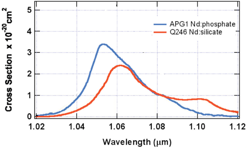
An example appears in Figure B.2, showing cross section data for two commonly used Nd-doped laser glasses. With such a broad effective linewidth, Nd:glass lasers can generate and amplify sub-ps-duration pulses.
For solid-state laser generation and amplification of pulses in the femtosecond range, linewidths broader than shown in the figure are required. A 10-fs sech2 pulse transforms to a 32 THz linewidth, about 100 nm for a 1,000-nm laser. Such large linewidths are possible but require a stronger interaction between the laser ion and the host than is found for rare-earth ions when the transitions remain among levels in the 4f shell. For that interaction, when the ion energy-level changes the relatively tightly bound and compact 4f wavefunctions do not create a major perturbation to the surrounding environment as they change from one energy level to another, and the distances from the laser ion to the nearby ions remain unchanged. For 3d-transition-metal ions the case is generally different, as the d-electron wavefunctions have a larger spatial extent and a more profound impact on the surrounding ions when they change state.
Figure B.3 illustrates the difference in the interaction. We plot the laser-ion energy level as a function of the distance from the surrounding ions, for the simple case where all of these ions change position in the same manner, the so-called “breathing mode” of ion motion. There is some minimum energy of the overall system, an equilibrium position, such that a displacement in either direction leads to a higher energy. The surrounding ions will vibrate about this position (quantized
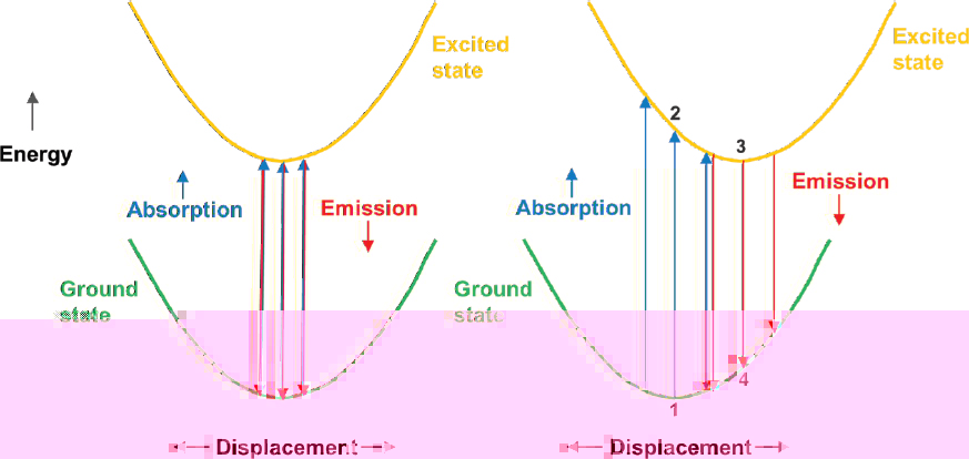
as phonons) at a frequency determined by the particular host. In Figure B.3(a) when the ion energy level changes the equilibrium position does not change the case, as we noted, for transitions between 4f energy levels. This is also true for the first (ruby) laser transition at 694.3 nm based on 3d Cr3+ ions in Al2O3, where the only difference in electronic states is the spin configuration, and the spatial nature of the wavefunction does not change. The more general case for 3d laser-active ions is that an energy-level change does result in a new equilibrium position, as illustrated in Figure B.3(b). The effect of this equilibrium shift is profound on the linewidth of the transitions, both upward (absorption) and downward (emission), associated with laser operation. The key physics in the absorption and emission processes are that the electronic transitions occur so quickly (on the order of 10–16 seconds) that the surroundings do not have time to adjust position, but do so (in about 1 ps) only after the transitions take place. In the figure, we label one absorption transition from point 1 to 2, and an emission transition taking place, after the system has reached the new equilibrium position, from points 3 to 4. It is evident that the absorption and emission have different energies. Since there is vibration about the equilibrium point, there is a distribution of energies for both absorption and emission, leading to a broadened linewidth for both.
The type of transition illustrated in Figure B.3(b) is often referred to as “vibronic,” a mix of vibrational and electronic, and also “phonon broadened,” but this is less precise, as we noted above that phonons play a role in determining linewidth even for the case of no equilibrium shift.
In contrast to the ruby laser, other early solid-state lasers operated on 3d-ion vibronic transitions. L.F. Johnson and co-workers in 1963 reported “optical maser oscillation from the 3d Ni2+ ion in MgF2 involving simultaneous emission of phonons,”1 and later operation from Co2+ and V2+ ions,2 where broad wavelength tuning was achieved. The major drawback to these first vibronic lasers was that, because of thermally induced non-radiative processes between the laser energy levels, relatively low-threshold operation with lamp pumping required cooling of the laser crystals to cryogenic temperatures.
Moulton reported the first laser operation from the 3d ion Ti3+ in the same host crystal Al2O3 (sapphire, the material, not the gemstone) used for the ruby laser,3 with more details on that provided later.4Figure B.4 shows Ti:sapphire
___________________
1 L.F. Johnson, R.E. Dietz, and H.J. Guggenheim, 1963, Optical maser oscillation from Ni2+ in MgF2 involving simultaneous emission of phonons, Phys. Rev. Lett. 11(7): 318-320.
2 L.F. Johnson, and H. J. Guggenheim, 1967, Phonon terminated coherent emission from V2+ ions in MgF2, J. App. Phys. 38(12): 4837-4839.
3 P.F. Moulton, 1982, Titanium-doped sapphire: A new tunable solid-state laser, in Physics News (Phillip F. Schewe, ed.), American Institute of Physics.
4 P.F. Moulton, 1985, Spectroscopic and laser characteristics of Ti:AI2O3, J. Opt. Soc. Am. B 3(1): 125-133.
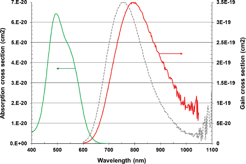
cross sections for absorption and emission from the lowest energy level of the ion to the first excited state, clearly a vibronic transition. The difference between the observed emission spectrum and the gain cross section reflects corrections needed to follow Einstein’s formulation for gain from stimulated emission.5 Of note is the very broad gain linewidth, about 100 THz. This has allowed generation of 3.6-fs-duration pulses at 800 nm,6 slightly more than one optical cycle, the shortest yet generated directly by a laser.
___________________
5 A. Einstein, 1917, Strahlungs-emission und -absorption nach der Quantentheorie, Physika Zeitschrift 18(121).
6 S. Rausch, T. Binhammer, A. Harth, F. X. Kaertner, and U. Morgner, 2008, Few-cycle femtosecond field synthesizer, Opt. Exp. 16(22): 17410-17419.
Petawatt-Class Solid-State Lasers, Criteria
Table B.1 lists important characteristics of laser materials. We include the saturation fluence, Esat, which is given by the relation
| Esat = hc / (λσ), | (B.3) |
with h Planck’s constant, c the speed of light, λ the laser wavelength, and σ the peak laser transition cross section. In Table B.1, we use this simplified relation, which assumes that the absorption cross section can be ignored, appropriate for the materials we consider. (If absorption cannot be ignored, the denominator should be the sum of the two cross sections.) For a laser pulse to efficiently extract the
TABLE1 B.1 Key Characteristics of Common Solid-State Laser Materials
| Material | Wavelength (nm) | Storage time (msec) | Cross section (cm2) | Gain linewidth (nm) | Saturation fluence (J/cm2) |
|---|---|---|---|---|---|
| 4f rare-earth dopants | |||||
| Nd:YAG | 1064 | 0.24 | 2.8 x 10⁻¹⁹ | 0.6 | 0.66 |
| Nd:YVO4 | 1064 | 0.09 | 1.1 x 10⁻¹⁸ | 1.0 | 0.17 |
| Nd:YLF | 1047 | 0.485 | 1.8 x 10⁻¹⁹ | 1.0 | 1.0 |
| Nd:glass | 1050-1060 | 0.3-0.4 | 3-4 x 10–20 | 20-30 | 4.7-6.3 |
| Yb:YAG | 1030 | 0.95 | 2.1 x 10⁻²⁰ | 9 | 9.2 |
| Yb:YAG (77K) | 1030 | 0.85 | 1.1 x 10⁻¹⁹ | 1.5 | 1.8 |
| Yb:CaF2 | 1030 | 2.4 | 3.0 x 10⁻²¹ | 50 | 64 |
| Yb:CALGO | 1040 | 0.4 | 7.5 x 10⁻²¹ | 70 | 25 |
| Yb:S-FAP | 1047 | 1.1 | 6.1 x 10⁻²⁰ | 4 | 3 |
| Er:YAG | 1645 | 7.6 | 5.0 x 10⁻²¹ | 5 | 24 |
| Er:glass | 1550 | 7.9 | 8.0 x 10⁻²¹ | 55 | 16 |
| Ho:YAG | 2090 | 8.5 | 1.3 x 10⁻²⁰ | 25 | 7.3 |
| Ho:YLF | 2050 | 15 | 1.8 x 10⁻²⁰ | 25 | 5.3 |
| 3d transition-metal dopants (vibronic transitions) | |||||
| Co:MgF2 (77K) | 1900 | 1.4 | 1.5 x 10⁻²¹ | 600 (50 THz) | 68 |
| Cr:BeAl2O4 | 755 | 0.26 | 7 x 10–21 | 55 (29 THz) | 37 |
| Cr:LiSAF | 850 | 0.067 | 5.0 x 10⁻²¹ | 190 (85 THz) | 4.7 |
| Ti:sapphire | 800 | 0.0032 | 2.5 x 10⁻¹⁹ | 225 (100 THz) | 1.0 |
| Cr:ZnSe | 2450 | 0.006 | 1.3 x 10⁻¹⁸ | 1000 (50 THz) | 0.06 |
NOTE: All data for materials at 300 K unless noted.
energy stored in the upper laser level, the incident fluence, for one pass through the laser material, should be several times the saturation fluence. For systems that pass the laser pulse through the material multiple (N) times, the amount required for efficient extraction can be divided by N, provided the energy does not decay during the time required for the multi-pass process.
We noted in the Technology History section a major challenge in the direct amplification of ps- and shorter-duration pulses would be damage to the laser material and associated optics. If we assume a saturation fluence of 5 J/cm2, the peak power incident of the laser material for efficient single-pass extraction with a 1-ps pulse would be 5 TW/cm2, much greater than the ps-pulsewidth optical damage limit for common materials and optical coatings. The invention of chirped-pulse amplification [Mourou, Strickland] provided a solution to this problem through stretching of pulses into the ns region. For pulses of that duration, typical optical damage thresholds are as high as 40 J/cm2 for uncoated silica optics to as low as several J/cm2 for anti-reflection coatings. Other limits may set in from nonlinear effects in the laser material.
If we consider laser materials suited for high-energy, ps and shorter-pulse CPA systems, there are several criteria:
The gain linewidth must be sufficiently large to allow amplification for the desired pulsewidth. This criterion is more stressing than for simple mode-locked pulse generation since there is a large amount of amplification required to take the typical 10s of nanoJoules (nJ) pulse energy from a mode-locked laser to the J and higher level. High amplifications act to narrow the effective bandwidth of the laser material through gain narrowing, the result of the gain spectral function being raised to some higher power, depending on the required amplification.
The saturation fluence must be low enough to allow good extraction of energy stored in the laser medium before optical damage to the laser material or associated optics. While multi-passing of the extraction beam can improve extraction efficiency, this also requires that the material have sufficient gain bandwidth to overcome the gain narrowing that becomes more problematic as the number of passes increases. For saturation fluences above 10 J/cm2 efficient extraction is problematic.
The laser material must be capable of being optically pumped with good conversion of pump energy into stored energy. Until the last decade, the only practical, affordable pump source for high-energy systems was flashlamps or pump lasers based on flashlamps. Attached to this requirement is that the pump power must be delivered in a time comparable to the storage time, to obtain a high stored energy.
Given the need to increase, at high energies, the area of the laser beam doing extraction, the laser material has to be able to be grown, in the case of crystals, or fabricated, in the case of glasses, in sufficiently large size to accommodate the area of the extraction beam.
There must exist techniques to avoid, at large material sizes, the inability to store energy due to (1) spurious laser operation in the material due to formation of laser cavities based on internal reflections inside the material or (2) excessive optical gain, in a direction along that of the gain or, for large beam sizes, along the width of the beam. This high gain leads to ASE that arises from decay of the upper laser level and leads to depletion of stored energy. Unfortunately, the issue of ASE becomes more pronounced for materials with large cross sections and thus low saturation fluences, which otherwise facilitate efficient extraction.
The first two criteria eliminate many of the materials listed in Table B.1, due to limited bandwidth, too high a value for saturation fluence, or, in a few cases, too low a value. Equation B.2 points out the fundamental relations between storage time, gain cross section (and hence saturation fluence), and linewidth, and one result is the challenge in finding materials that have both large linewidth and a low Esat. Other materials that pass the first criteria have, until recently, suffered from poor efficiencies with lamp pumping (notably the Yb- and Ho-doped crystals) since they do not have a multiplicity of high-lying energy levels that overlap with the emission spectra of lamps. As we note in Appendix B3, such materials may emerge as high-peak-power sources in the future with the development of diode and other pumping techniques.
Petawatt-Class Nd:glass Lasers
Background of Nd:glass Lasers
The glass materials used as hosts for the Nd ion belong to a very large category of optical glasses. In general, glasses are amorphous materials and, in contrast to crystals, have no organized structure that extends past several clusters of atoms. Another property of glass is the presence of a glass transition from a hard to a “rubbery” state as the material temperature is increased to a certain level, but below the point at which the material turns liquid. Transparent glasses are characterized by formers that make up most of the glass, and these are typically oxides of Si, B, Ge, or P, although there are glasses based on metallicfluoride formers and mixes of oxide and fluoride formers. Other components of the glass, network modifiers, typically alkali-based (e.g., Na and Ca) are added to control specific glass properties. The most widely used glass for photonics is pure silica (SiO2), the basis for optical fibers for telecom and lasers, while common window glass is 72 percent silica mixed in with oxides of Na, Ca, Mg, and Al.
The first Nd:glass laser was demonstrated by Snitzer in 1961.7 The potential to scale glass lasers to high energies has led to their extensive development for ICF,
___________________
7 E. Snitzer, 1961, Optical maser action of Nd3+ in a barium crown glass, Phys. Rev. Lett. 7: 444.
which has funded Nd:glass-laser research since the 1970s. Key requirements of laser glass for ICF, besides desirable laser-spectroscopic, nonlinear-optical, thermal, and mechanical properties, are the ability to fabricate the material in large, optically uniform slabs, which have to be free of impurities and defects that would lead to optical damage in the material.
Glass Categories and Manufacture
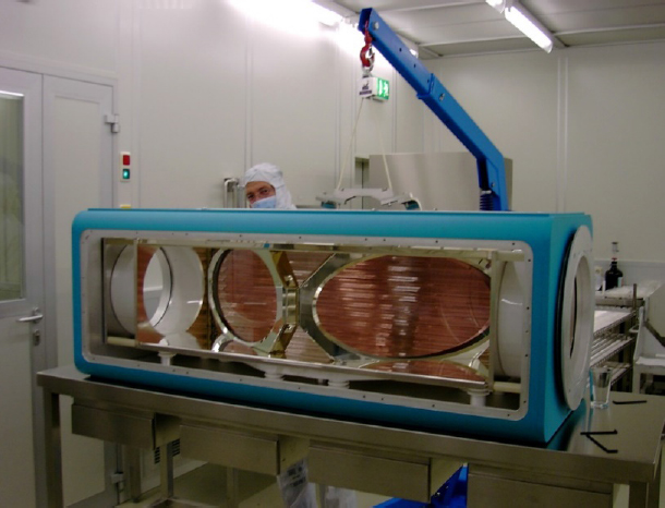
The main categories of laser glass are silicate, phosphate, and fluorophosphates. The first glasses used for ICF work were silicates, but at present, phosphate glass (typically 60P2O5 – 10Al2O3 - 30M2O/MO, where M stands for a metallic ion) has become the glass category of choice, as it can be fabricated in large sizes free of the metallic inclusions that plague other glasses.8Figure 2.1 is a photograph of a large slab of unpolished Nd-doped phosphate glass, shown in a facility developed to provide the size of glass needed in the Lawrence Livermore National Laboratory (LLNL) National Ignition Facility (NIF).
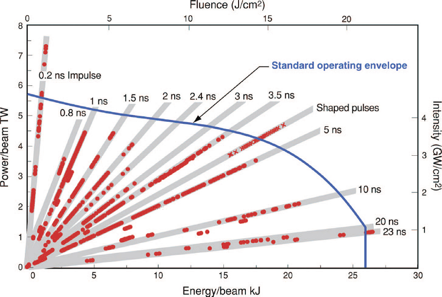
In terms of amplifier performance, Figure B.5 provides a good illustration of the relation among operating fluence, pulsewidth, and output energy, for the case of the present 1053-nm NIF final amplifier stage, which operates with a square beam cross section of 37.2 cm and a double-pass configuration.9 At short pulsewidths, energy limits come about from nonlinear effects in the glass, which lead to the generation of intensity peaks in the beam and optical damage to the material, while at long pulsewidths the limit is from the available input energy to the amplifier.10 The reduction in allowable output energy with shortening pulsewidth illustrates why the CPA technique is key to generating PW-class laser systems. For several-ns-duration pulses the amplifier operates efficiently, at 23x the Nd:glass saturation fluence. As another example, the Laboratory for Laser Energetics (LLE) Omega system runs conservatively with a final stage, single-pass amplifier fluence of up to 3.6 J/cm2 with temporally shaped, 0.1 to 4-ns pulses.
The high operating fluences used at the NIF and in other facilities are the result of substantial development of polishing and coating technology over several decades that has allowed relatively damage-free operation at increasingly higher levels. The NIF system runs with fluences on the UV-wavelength optics that do lead to occasional damage, but includes techniques to mitigate the effects of localized damage and reduce further growth of damaged regions, as well as means to easily
___________________
8 J.H. Campbell, J. S. Hayden, and A. J. Marker, 2011, High-power solid-state lasers from a laser glass perspective, International Journal of Applied Glass Science 2(1): 3-29.
9 C.A. Haynam, P. J. Wegner, J. M. Auerbach, M. W. Bowers, S. N. Dixit, G. V. Erbert, G. M. Heestand, et al., 2007, National Ignition Facility laser performance status, Appl. Opt. 46(16): 3276-3303.
10 C.A. Haynam, et al., 2007, National Ignition Facility laser performance status.
service components when the damaged regions grow to the point that the optics are unusable.
Glass Thermal Limitations
The many favorable properties of glasses for high-energy lasers are accompanied by a significant limitation. Due to the lack of long-range structure, glass has poor thermal conductivity, as phonons that transport heat in electrically insulating materials like glasses cannot travel far without being scattered. The conductivities of common laser glasses are about 25x lower than for YAG, a common laser host, and about 50x lower than sapphire. In the process of heat generation in the laser that is a natural outcome of the pumping-lasing process, the flow of heat out of the material creates a temperature gradient that in turn creates optical distortion,
through the material change of refractive index with temperature. In addition, the stress in the material from the gradient (due to differential thermal expansion) leads to optical distortion from the stress-optic effect, primarily the creation of birefringence that depolarizes the linearly polarized light that is required in systems needed to drive nonlinear optics or work efficiently with grating compressors. Ultimately, large thermal gradients create enough stress to fracture the material.
In comparing laser materials, the thermal shock parameter, RT, provides an indication of the ability of a given material to handle a high thermal load without fracturing, and is given by the relation:
| RT = κ σT (1 - ν) / (α E), | (B.4) |
where κ is the thermal conductivity, σT is the tensile strength of the material, ν is the material Poisson ratio, α is the thermal expansion coefficient, and E is the Young’s modulus. The only parameter not purely intrinsic to a material is the tensile strength, which can vary depending on the nature of the surface finish of a material. (Fracture can start at a location of a “flaw” or “micro-crack” on the surface.)
While the exact amount of thermal load a laser material can handle depends on the geometry of the system, the value is proportional to RT and thus the quantity does provide a way to compare different materials under the same conditions. While glasses can be engineered to have a low thermal expansion coefficient (pure silica glass and zerodur are examples), those glasses do not make good hosts for high concentration levels of rare-earth ions. The low thermal conductivity and resultant low thermal shock parameter of laser glasses remains a major limit to their average-power output. Typical laser glasses have values of the thermal shock parameter in the 40-140 W/m range, while crystal hosts such as YAG and sapphire have values of 1,450 and 3,400, respectively.11
The problems of poor thermal conductivity in glass are magnified by the large material volumes required for high energies, which lead to relatively long paths for heat flow and thus large temperature gradients. High-energy systems, to date, mainly operate at such low pulse rates (several per min to per day) that heat in the glass material can be fully removed before the next pulse is generated, and thus long-term gradients do not develop. (We also discuss later how higher pulse rates in glass lasers have been enabled by diode-laser pumping and/or advanced thermal-management techniques.)
Early glass lasers, like other solid-state lasers, were fabricated in the shape of rods, well matched to the cylindrical geometry of pump lamps, but also subject to
___________________
11 W.F. Krupke, 1983, Insulator materials in high power lasers for inertial fusion: Present and future, MRS Proceedings 24: 401;W.F. Krupke, 1999, Materials for lasers and nonlinear optics, in Advances in Lasers and Applications (D.M. Finlayson and B. Sinclair, eds.), CRC Press.
major thermo-optic distortion since the heat flow, and hence temperature gradient, is perpendicular to the laser beam. The beam experiences different optical paths depending on the point in the beam cross section, as well as stress-induced birefringence. High-energy glass laser designs evolved to use relatively thin, multiple disks, designed with flashlamp illumination to be uniformly pumped. In that design the thermal gradient is primarily along the laser beam, and thus all parts of the beam experience nearly the same optical path. The ultimate limitations due to thermal fracture remain the limit to pulse rate and hence laser average power.
Petawatt Glass System Examples
At present there are a number of PW-class, Nd:glass-based systems worldwide, as shown in Table 4.2 from Chapter 4. We present details on a selected few of these.
First Petawatt Laser
The first PW laser system employed CPA technology and included a Ti:sapphire mode-locked laser at 1,054 nm, with output pulses stretched to about a 3-ns pulsewidth, Ti:sapphire pre-amplifier stages, Nd:glass rod amplifiers, and, at high energies, disk amplifiers based on phosphate glass.12 It was constructed at LLNL, crossed the PW-peak-power threshold in 1996 and by 1998 had reached 1.5 PW of peak power, with 660 J of energy in a 440-ps pulse. For this system one key technology was large-aperture, flashlamp-pumped, disk-geometry amplifiers, as shown in Figure B.6, developed primarily for applications to ICF studies and incorporated in the NOVA laser, the fore-runner to the present NIF system. Such amplifiers convert about 1-1.5 percent of the electrical energy input to the lamps into stored energy in the laser medium. The large size of the glass disks in NOVA limited operation to 6 firings/day. The system was de-commissioned in 1999 to make room for the present NIF laser system.
A key part of the LLNL PW-laser effort involved development of techniques to fabricate large-diameter optical gratings, needed to compress the high-energy stretched pulse and not suffer from optical damage. The system employed LLNL-developed, 94-cm-diameter gratings, which represented a major advance in grating-fabrication technology.13Figure 2.2 shows one of the gratings mounted in the compressor system, which, as with other high-peak-power systems, must operate in a vacuum to avoid air breakdown by the pulse. The LLNL metallic gratings could operate reliably
___________________
12 M.D. Perry, D. Pennington, B. C. Stuart, G. Tietbohl, J. A. Britten, C. Brown, S. Herman, et al., 1999, Petawatt laser pulses, Opt. Lett. 24(3): 160-162.
13 M.D. Perry, “Crossing the Petawatt Threshhold,” Lawrence Livermore National Laboratory, December 1996, https://str.llnl.gov/str/Petawatt.html.
at fluences of 0.33 J/cm2.14 Large-area gratings remain a key technology component to any CPA-based systems used at the PW level.
Texas Petawatt Laser
Of interest is the so-called “Texas Petawatt Laser,” at the University of Texas at Austin, which employs a combination of technologies to produce a relatively short pulsewidth (130 fs) for a Nd:glass-based system. The system diagram (Figure B.7) shows that the Nd:glass amplifier stages use a mix of silicate and phosphate glass, which in combination provide a broader amplifier spectral bandwidth than possible with a single type of glass host.15Figure B.2 shows the effect of the glass former on the spectrum of the laser gain cross section. In general, silicate glasses present a larger crystal field to the Nd ion, leading to a larger splitting of the lower (multiple) energy levels of the laser transition, and thus a broader linewidth, shifted
___________________
14 M.D. Perry, et al., 1999, Petawatt laser pulses.
15 E.W. Gaul, M. Martinez, J. Blakeney, A. Jochmann, M. Ringuette, D. Hammond, T. Borger, et al., 2010, Demonstration of a 1.1 petawatt laser based on a hybrid optical parametric chirped pulse amplification/mixed Nd:glass amplifier, Appl. Opt. 49(9): 1676-1681.
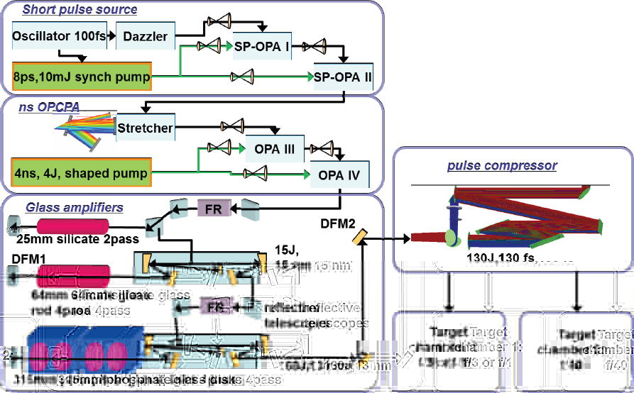
somewhat towards longer wavelengths compared to the phosphate glasses. As with the first PW-level laser at LLNL, the system employs a final stage, phosphate-glass disk amplifier based on the NOVA stage shown above.
Another important design feature of the system, now becoming a common feature of PW-class lasers, is the use of a high-gain, broad-linewidth optical parametric amplifiers (OPAs), both for the Ti:sapphire-laser-generated mode-locked pulse as well as for the stretched pulse. For the latter, the devices are referred to as optical parametric chirped-pulse amplifiers (OPCPAs). We discuss the technology of parametric amplifiers in Appendix B2 in reference to their application as both preamplifiers and as the final stage amplifiers in PW-class systems. The devices provide a broad-bandwidth, high-energy input to the glass amplifier stages, which operate with a total gain of less than 200, reducing the effect of gain narrowing. Another feature of the system is the use of a “Dazzler,” the trade name for an acousto-optic based device that provides control of the phase and amplitude distribution of the frequency spectrum generated by the mode-locked laser. Adjustment of this spectrum allows better control of the output of the system, by correcting for distortions that act to broaden the compressed pulsewidth. The net combined
gain with the phosphate and silicate glasses supports an output bandwidth for the Texas Petawatt of 13 nm, centered at 1,057 nm, allowing compression to the 130-fs-pulsewidth region. The system pulse rate is 1 per hour.
In Appendix B3 we discuss the outlook for Nd:glass PW systems, where we show how replacement of flashlamps with diode-laser pumps, combined with advance cooling techniques can increase the system pulse rate, and the use of mixed-glass approaches, and possibly new glass materials can lead to shorter pulses.
Petawatt-Class Ti:sapphire Lasers
Background of Ti:sapphire Lasers
Beyond the clear difference in laser spectroscopic properties, compared to glass host materials the sapphire host crystal can handle a much higher thermal load and thus can operate at a much higher average power. As noted above, the thermal shock parameter for the material is about 25-80x higher than for laser glasses.
The shorter pulses generated by Ti:sapphire amplifier systems (15-30 fs) allow at least 6x lower energies to reach the PW level compared to Nd:glass systems. Laser-based pumping of Ti:sapphire, due to the short storage time of the material, is the universal approach to high-power system operation. At present, commercial “tabletop” Ti:sapphire oscillator-amplifier systems are available approaching the TW/pulse level (30 mJ in 30-40 fs), at rates as high as 1 kHz, with custom systems at PW-level powers advertised as available from two French-based companies, Thales and Amplitude Technologies. The general approach to building the higher-energy “custom” systems is to employ multiple identical pump lasers, each of which is engineered to operate at an energy and average power limited by the choice of the laser technology, at this writing based on either lamp-pumped Nd:YAG or Nd:glass lasers. Energy- and average-power scaling is done by adding more pump lasers, up to technical limits set by ASE, thermal effects in the Ti:sapphire final stage amplifier, or practical limits set by funding. The alternative is to employ a high-energy, single-stage Nd:glass-laser based pump, with the limits to average power then set by the performance of the pump. In the following we show examples of both approaches.
Berkeley Lab Laser Accelerator
The Berkeley Lab Laser Accelerator (BELLA) is unique, at present, in that it operates at a > 1 PW power level with a pulse rate as high as 1/second. Of interest is that it was constructed by a commercial laser supplier, Thales Optronique (Elancourt, France), rather than by a National Laboratory or an academic institution, and was claimed to be the first “commercial” PW laser. Figure B.8 shows a schematic of the system, with many of the components labeled with commercial

trade names. Details of the system have been published,16 and we briefly summarize them here to point out important PW-system technologies of general interest. The configuration in Figure B.8 is referred to as a “double CPA.”
800-nm-centered, < 10-fs-duration, 100-nm-bandwidth pulses from a mode-locked Ti:sapphire laser are initially stretched to 150 fs, amplified, by about 2 × 10⁵, through use of a highly multipass (regenerative) Ti:sapphire amplifier, where gain-narrowing reduces the pulse bandwidth to 35 nm, then recompressed and passed through a cross-polarized wave (XPW) element. The latter is used to minimize energy before the main pulse in time (prepulse), i.e., to improve, in the initial stages
___________________
16 F. Lureau, S. Lauxa, O. Casagrandea, C. Radiera, O. Chalusa, F. Caradeca, and C. Simon-Boissona, 2012, High energy 1 Hz Titanium Sapphire amplifier for PetaWatt class lasers, in Solid State Lasers XXI: Technology and Devices (W. A. Clarkson and R. K. Shori, eds.), Proc. of SPIE, Vol. 8235, doi: 10.1117/12.908127.
of the system, the “contrast ratio” of the pulse. Prepulse energy is typically generated by ASE in the regenerative amplifier and also arises from incomplete suppression of other pulses emerging from the high-pulse-rate mode-locked source laser. For many scientific applications, particularly interaction with solid targets and plasmas, any energy arriving before the main pulse can ionize or otherwise perturb the target and modify the interaction. In XPW, a crystal, or two, (typically BaF2) is placed between two crossed polarizers and the pulse to be improved in contrast is focused through the input polarizer onto the crystal.17 The third-order nonlinear response of the crystal leads to the generation of a beam in the crystal with an orthogonal polarization, which passes through the output polarizer. Since the transmitted pulse energy depends on the cube of the pulse intensity, lower-energy (pre-pulse) light is significantly attenuated. An added benefit of the XPW element is the nonlinear interaction adds some bandwidth back to provide shorter pulse. For the BELLA system, the use of XPW increased the pulse contrast ratio by about 4-5 orders of magnitude to the present operating level of about 1 × 10⁻¹⁰, for energy contained in a 1-ns time around the main pulse.
The second CPA system employs pulse stretched to the ns level and a series of staged Ti:sapphire amplifiers, all pumped by doubled Nd:YAG lasers. Thales developed an advancement in this technology through use of 25-mm-diameter Nd:YAG rod amplifiers, which facilitated construction of pump lasers that generate 14 J of green pulse energy at a 1-Hz rate. Eight of these sources are used to pump the final, two-pass Ti:sapphire amplifier, which uses a 12-cm-diameter crystal and a 7-cm-diameter pump/extraction beam. For a total of 112 J of pump energy, about 60 J is output (with 39 J extracted) at 800 nm. The compressor employs “commercial” 48.5 × 30-cm gold-coated diffraction gratings manufactured by Horiba Jobin-Yvon in France. At present the system, a photograph of which appears in Figure 2.3, operates at the 40 J output level with a 30-ps pulse, for a peak power of > 1.3 PW.
While Ti:sapphire systems can operate at lower energies to reach the PW level compared to Nd:glass, the larger gain cross section of the gain medium presents an ASE challenge, notably in the large-diameter disk-configuration final stages where the gain transverse to the extraction beam can lead to significant losses in stored energy and/or parasitic oscillations arising from reflections at the disk edges. In high-energy glass lasers the outer edges of the disks are clad in an index-matched glass doped to absorb the relatively narrow-linewidth emission around 1,050 nm. In Ti:sapphire the challenge is heightened by the large refractive index of the host, the scarcity of suitable index- and thermal-expansion-matched solid materials, and the broad bandwidth of the emission. For BELLA, Thales surrounded the
___________________
17 A. Jullien, O. Albert, F. Burgy, G. Hamoniaux, J-P. Rousseau, J-P. Chambaret, F. Augé-Rochereau, et al., 2005, 10−10 temporal contrast for femtosecond ultraintense lasers by cross-polarized wave generation, Opt. Lett. 30(8): 920-922.
Ti:sapphire disk edge with an index-matched liquid, with a broad-band absorber dye dissolved in the liquid, and water-cooled the liquid to allow operation of the laser at a 1-Hz rate.18
Shanghai Institute of Optics and Fine Mechanics (SIOM): Ti:sapphire
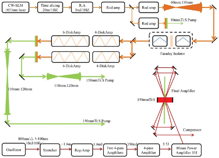
At present, a high-peak-power Ti:sapphire laser (2 PW, 53.2 J in 26 fs) has been operated at SIOM, employing a single-beam Nd:glass laser as the pump source.19 In addition, a 5.3-PW system pumped by two beams has recently become operational.20Figure B.9 is a simplified schematic of the 2-PW system, while Figure B.10 shows the 5.3-PW system design. As with the BELLA laser, the SIOM systems employ a XPW element, leading to a claimed contrast ratio of 1.5 × 10⁻¹¹ in the period of 100 ps before the main pulse.21 After the high-contrast front end, the pulse passes through a series of amplification stages to the final amplifier.
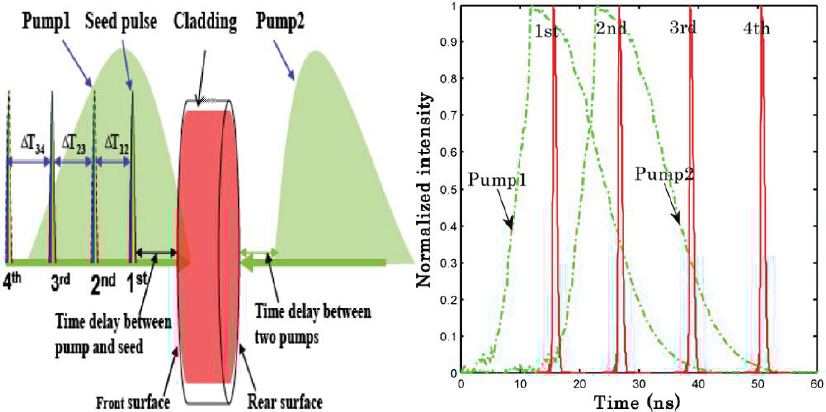
The final amplifier design in both the 2-PW and 5.3-PW systems employs several techniques to minimize the effects of ASE. Figure B.11 shows a schematic representation of the final amplifier design with pumping and extraction approaches illustrated.
As with the BELLA laser, the Ti:sapphire disks use a cladding consisting of an index-matching liquid containing an IR-absorbing dye. The most effective ASE suppression comes about through a technique referred to as extraction during pumping (EDP),22 which makes use of the timing of multiple extraction passes through the amplifier to control the excited-state population in the laser material. EDP is only available to ns-pulse-pumped lasers such as Ti:sapphire. The final amplifiers in the two SIOM systems have four-pass designs, with delays set by propagation distances for the extraction beams, as shown in Figure B.11. In addition, for the 5.3-PW system, the two pump beams, directed on each surface of the disk, are delayed with respect to each other. The extraction process, rather than
___________________
18 S. Laux, F. Lureau, C. Radier, O. Chalus, F. Caradec, O. Casagrande, E. Pourtal, et al., 2012, Suppression of parasitic lasing in high energy, high-repetition rate Ti:sapphire laser amplifiers, Opt. Lett. 37(11): 1913-1915.
19 Y. Chu, X. Liang, L. Yu, Y. Xu, L. Xu, L. Ma, X. Lu, et al., 2013, High-contrast 2.0 Petawatt Ti:sapphire laser, Opt. Exp. 21(24): 29231-29239.
20 Y. Chu, Z. Gan, X. Liang, L. Yu, X. Lu, C. Wang, X. Wang, et al., 2015, High-energy large-aperture Ti:sapphire amplifier for 5 PW laser pulses, Opt. Lett. 40(21): 5011-5014.
21 Y. Xu, X. Guo, X. Zou, Y. Li, X. Lu, C. Wang, Y. Liu, et al., 2013, Pulse temporal quality improvement in a petawatt Ti:sapphire laser based on cross-polarized wave generation, Opt. Commun. 313: 175–179.
22 V. Chvykov, and K. Krushelnick, 2012, Large aperture multi-pass amplifiers for high peak power lasers, Opt. Commun. 285(8):21342136; V. Chvykov, V. Yanovsky, S-W. Bahk, G. Kalintchenko, and G. Mourou, 2003, paper CWA34 presented at the Conference on Lasers and Electro-Optics, Baltimore, Md., June 1–6, OSA Technical Digest.

starting when all the pump energy has been accumulated in the gain medium, is timed to extract some of the stored energy at different times during the pumping process. The timing of the two pump pulses also helps to manage the peak stored energy in the 5.3-PW system. This reduces the maximum transverse gain to predicted values, respectively, of around 800 and 1,750 for the 82-mm-diameter beam in the 2-PW system and the 120mm-beam in the 5.3 PW system. The conversion efficiencies of pump to output energy for the 2 PW laser were 47 percent (72.6 J output before compression) and 50 percent for the 5 PW system, which generated 192 J of energy. By using 65-cm × 37.5-cm gratings, the SIOM group has obtained 24-fs, 5.3PW pulses (127 J), in a ~300mm laser beam.23
___________________
23 R. Li, L. Yu, Z. Gan, C. Wang, S. Li, Y. Liu, X. Liang, et al., 2016, “Development of a Super Intense Laser Facility at Shanghai,” presentation at IZEST Conference Extreme Light Scientific and SocioEconomic Outlook, Paris, Nov. 25-29.
At present there are a number of 0.1 PW and higher Ti:sapphire-based systems worldwide, as shown in Table 3.3 in Chapter 3. We return to a discussion of this technology in Appendix B3 in terms of future advances.
APPENDIX B2 NONLINEAR OPTICS AND OPTICAL PARAMETRIC CHIRPED-PULSE AMPLIFICATION BACKGROUND
The discovery and development of lasers quickly allowed the related development of nonlinear optics, a field that could be predicted in theory but required the intensity produced by lasers to transition to a demonstration and then real applications.
Light entering an insulating material interacts with the electrons and atomic vibrations through a variety of processes. It can be absorbed by creating a vibration or promoting an electron to a higher energy level. Barring that, light creates a displacement of electrons and atoms, for low light intensities, in almost entirely a linear proportion to the electric field of the light. The linear term for polarization has the effect of making light propagate through the material at a slower speed than in a vacuum which varies with wavelength λ, where the speed is c/n, with c the vacuum speed of light and n the refractive index of the material. At higher intensities, the accurate modeling of the displacement, or polarization, requires the inclusion of terms that include the square, cube, and higher-orders of the electric field.
Specifically, the presence of polarization proportional to the square (second-order nonlinearity) of the electric field of the light permits generation of a polarization resulting from the product of two electric fields. This leads to several possibilities. If the two fields are the same frequency, the nonlinear polarization created has a component that is at twice the frequency of the light. This creates light at the “second harmonic” of the two fields, or equivalently, half the wavelength. Another possibility is that two fields can be different frequencies, and here there can be light created at either the difference in frequencies or at the sum of the two frequencies.
Second-order nonlinearity, for one incident beam of light, means that a material polarization is established in a direction that is the same whether the light electric field is positive or negative. Consider setting up a vector inside the material pointing in a certain direction. If this vector is flipped into exactly the reverse direction, and the material appears to the vector to have the same structure, the material is said to have inversion symmetry. For such materials (glass is a good example, but many crystals have this as well), the material will not have a second-order nonlinearity, as there can be no preferred polarization that follows the square of the electric field. Only crystals that lack inversion symmetry can have a non-zero second-order nonlinearity.
The processes of harmonic generation and mixing we describe can be modeled classically using Maxwell’s equations with the nonlinear polarization added in to the customary linear polarization terms for light propagation in a material. Solutions of these equations with two light waves show, in one solution, how two frequencies can generate light at the sum frequency, the intensity of which can increase as the waves propagate in the material, with a loss of energy at the two
frequencies. The same general equations show another solution where light at one frequency can generate light at two lower frequencies, provided the sum of the two new frequencies is equal to that of the original frequency. (The sum requirement follows from energy conservation, and from the viewpoint of quantum theory, the sum of the energies of the two new photons must equal that of the original photon.) The latter process, with nomenclature carried over from early work with microwave technology, is called optical parametric generation (OPG) or, when at least one of the lower frequencies is also present in the beam incident on the material, optical parametric amplification (OPA). When an optical cavity is used to provide feedback at the signal or idler wavelength (or both), the device is called an optical parametric oscillator (OPO). The incident power at the high frequency is called the pump, the higher of the two frequencies generated or amplified is the signal, and the lower the idler. Energy conservation requires that the power conversion of pump to signal and pump to idler is given by the ratio of the signal to pump and idler to pump frequencies, often referred to as the Manley-Rowe relation, which was derived from early work at radio frequencies.
The same equations show that to produce appreciable amounts of amplification as the light travels through the material, all the electric fields of the light waves involved need to maintain a constant phase relationship. If they do not, power conversion into the signal and idler flows backwards into the pump, then back to the signal and idler, in a periodic fashion through the material. As a result, it is impossible to obtain significant amplification. The process of arranging the three interacting frequencies to stay in phase is called, fittingly, phase-matching. The phase change per length of material at a given frequency ν, k(ν), is given by
| k(ν) = 2π n(ν)ν /c , | (B.5) |
where n(ν) is the refractive index at the frequency and c is the speed of light (in vacuum). In terms of the wavelength λ corresponding to the frequency above,
| k(λ) = 2π n(λ)/λ. | (B.6) |
For the parametric process, phase-matching requires
| kp = ks + ki , | (B.7) |
where the subscripts p, s, and i refer to the pump, signal, and idler, respectively.
If the refractive index of the material was a constant, then phase-matching would happen automatically given the other requirement for conservation of energy, but in all conventional materials the index varies with wavelength due to refractive dispersion. Typically, at visible and near-infrared wavelength it decreases
with wavelength. To overcome this, one can utilize birefringent crystals, which show a difference in refractive index depending on the polarization (i.e., the direction of the electric field) of light and the direction of propagation with respect to the crystal orientation. Birefringent phase-matching is the most common technique, although the development of artificially structured materials has allowed another variety, called quasi-phase matching.
The simplest birefringent crystal is uniaxial, that is, there is an “optic axis” in the material along which the refractive index experienced by the light in that direction is independent of its polarization. Light going along any other direction experiences a refractive index that is polarization dependent, where the difference in refractive index between different polarizations depends on the specific direction of propagation. By making use of this dependency, one can achieve phase-matching for the three wavelengths through the proper choice of polarizations for light at each wavelength. One simple case would be the pump polarized parallel and the signal and idler perpendicular to the optic axis, a scheme referred to as “Type I” phase-matching, for the case of crystals (called positive uniaxial) where the index for a given wavelength is higher for the perpendicular polarization. If it is lower (negative uniaxial), then one can reverse the polarizations of the pump, signal, and idler.
The requirement that a crystal be birefringent and also lack inversion symmetry greatly limits the number of materials that can be used for parametric processes. Further limits are set by other practical considerations, such as crystal quality, absorption at all the wavelengths involved, freedom from photochemical degradation at high light intensities, high optical-damage threshold, and, for use with high energies, ability to be grown in large sizes. The number of crystals suited for harmonic and parametric generation at high powers and energies, after about 60 years of development efforts, remains in the single digits.
One class of crystals, first used as acoustic transducers, and predating the development of lasers, are members of the KDP (KH2PO4) family. They are composed of compounds of alkali metals with light or heavy (hydro, deutero) water and oxides of phosphate or arsenate. Motivated by application to harmonic generation in ICF sources, several groups developed technology to grow nearly meter-aperture KDP and an isomorph, DKDP or KD*P, where almost all the hydrogen is replaced by deuterium. Two other materials, β-BaB2O4 (BBO) and LiB3O5 (LBO), first synthesized in China in the 1970s, have found widespread use in commercial parametric-based light sources. They are relatively robust crystals mechanically, with high optical damage thresholds, a wide transparency range, and, in the case of LBO, a very low level of optical absorption. Another borate material, YbCa4O(BO3)3 (YCOB), has also been used for some systems needing a large-aperture crystal.
One important point about parametric amplifiers is, in contrast to amplifiers based on stimulated emission, there is no energy storage in the nonlinear material. Gain is only present when the pump is on and is proportional to the pump intensity.
For the time the pump is on one can obtain very high gains with high-peak-power pump pulses, as high as 1012 and sufficient to build up a substantial signal and idler power with only the photon-level thermal noise background as input. Unlike lasers, there is no spontaneous emission background around the pulse in time, and the nature of phase-matching results in gain that is only in the general direction of the pump beam. Thus, scaling to large pump-beam sizes can be done without limits set by gain transverse to the beam. Also, unlike lasers, in the absence of any background absorption in the crystal, or absorption-inducing nonlinear effects in the material, the parametric process does not create any heat. All the incident energy is converted into light at other wavelengths.
Parametric Amplification of Broad-Spectrum Pulses
The advantages we have just outlined for parametric processes suggest they could be used for high-intensity generation of light, if a suitable high-energy pump laser is available. The other criterion is that the parametric gain has sufficient bandwidth to amplify an ultrashort pulse. If one utilizes a narrow-band pump laser, the bandwidth of an OPA is determined by how rapidly the phase-matching condition deviates from the condition set by equation B.7 as the signal frequency changes. Consider what happens to this condition as the signal frequency deviates by an amount Δν from the value at which phase-matching occurs. From energy conservation, the idler must deviate by –Δν, and we can approximate the new phase-matching requirement by the equation
| kp = ks + (dks /dv)Δν + ki – (dki /dν)Δν. | (B.8) |
We can write the derivatives as
| dks /dν = 2π/vs and dki /dν = 2π/vi, | (B.9) |
and thus
| kp = ks + ki + 2π Δν (1/vs – 1/vi ), | (B.10) |
where vs and vi are the “group velocities” for the signal and idler waves, respectively. These quantities describe the velocity of the peak position of a short pulse of light (centered at the frequency of the signal or idler) as it travels through the crystal. In the absence of any refractive dispersion this velocity would be the same as the velocity of a continuous wave of light at that frequency, but with dispersion the different frequency components that make up the pulse travel at slightly different speeds. The effect of this makes the peak of pulse move at a different speed. The
physical interpretation of equation B.6 is that the broadest bandwidth amplification arises when the group velocities of the signal and idler beams are matched, i.e., the pulses travel together through the nonlinear crystal.
For Type I phase-matching it is possible to have “degenerate” parametric amplification, where the signal and idler frequencies are the same. In that case group velocities for signal and idler waves are the same, the third term in equation B.6 vanishes, and phase-matching is maintained independent of the frequency change in the signal. This leads, in theory, to an infinite bandwidth, but in actuality the approximation of equation (B.4) is no longer valid and higher-order derivatives need to be considered. Nevertheless, the bandwidth does become large, and early work to use parametric gain to amplify short pulses employed systems operating around the degenerate point.
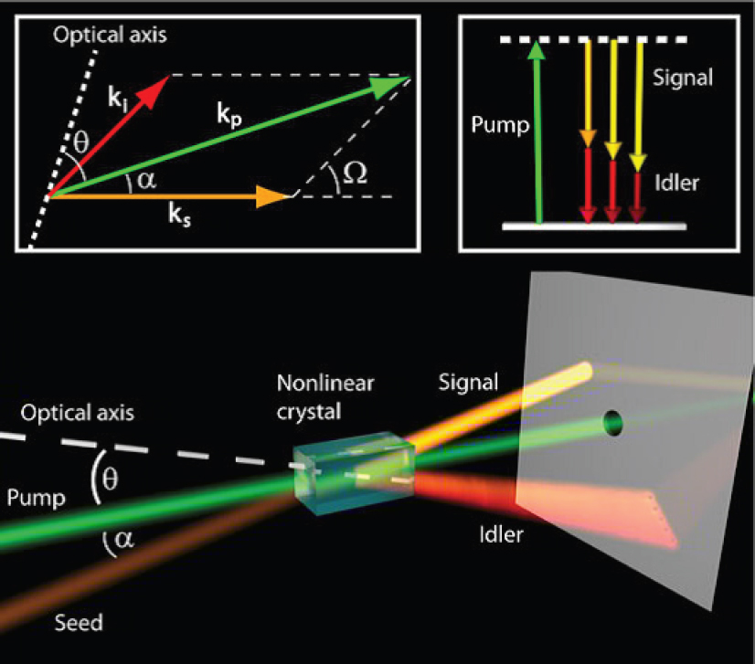
Experiments in the 1990s involving parametric amplifiers driven by ultrashort pulses demonstrated that a more complicated type of phase-matching could lead to even larger bandwidths than found with degenerate phase-matching.24Figure B.12 illustrates “non-collinear” phase-matching, where the constraint that the pump, signal, and idler beams travel in the same direction is eliminated. The significance of this scheme is that through the right combination of angles, not only is phase-matching possible, but it is also an excellent matching of group velocities of the signal and idler, well away from the degenerate case. An important point is that when amplifying a broad-bandwidth signal beam the angle for the idler wave can and does vary to facilitate phase-matching for the different frequency components in the signal. This degree of freedom is not available for collinear phase-matching.
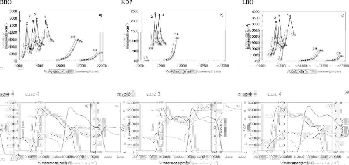
Figure B.13 shows calculated gain bandwidths with non-collinear phase-matching for three nonlinear materials, for a variety of pump wavelengths, as well as calculated gains as a function of frequency in cm–1. The latter unit is equivalent to a frequency of 30 GHz, and thus gain bandwidths in the 2,5003,500 cm–1 region correspond to 75-100 GHz linewidths, comparable to Ti:sapphire in spectral width. The actual computed gains, on the order of 1,000, have spectral widths, in the 90-120 GHz range, so in contrast to laser media it is possible to have significant amplification without gain narrowing. In fact, analysis of the gain bandwidth set by phase-matching conditions shows that the bandwidth increases with gain. Thus one can obtain high-gain amplification of several-fs pulses.
___________________
24 V. Krylov, A. Kalintsev, A. Rebane, D. Erni, and U. P. Wild, 1995, Noncollinear parametric generation in LiIO3 and b-barium borate by frequency-doubled, femtosecond Ti:sapphire laser pulses, Opt. Lett 20(2): 151-153; Di Trapani, A. Andreoni, G. P. Banfi, C. Solcia, R. Danielius, A. Piskarskas, P. Foggi, et al., 1995, Group-velocity self-matching of femtosecond pulses in noncollinear parametric generation, Phys. Rev. A 51(4): 3164-3168.
Petawatt-Class Optical Parametric Chirped-Pulse Amplification Systems
Russian Optical Parametric Chirped-Pulse Amplification Systems
The PEtawatt pARametric Laser (PEARL) system, built at the Institute of Applied Physics, Russian Academy of Science in Nizhny Novgorod,25 utilizes KD*P crystals, which, when pumped at 527 nm, show a gain bandwidth peaked at 910 nm
___________________
25 V.V. Lozhkarev, G.I. Freidman, V.N. Ginzburg, E.V. Katin, E.A. Khazanov, A.V. Kirsanov, G.A. Luchinin, et al., 2007, Compact 0.56 Petawatt laser system based on optical parametric chirped pulse amplification in KD*P crystals, Laser Physics Letters 4(6): 421.
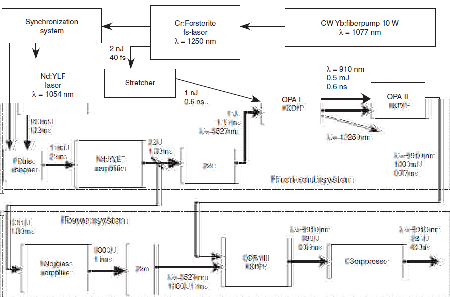
and capable of amplifying 10-15-fs-duration pulses. Figure B.14 shows a schematic diagram of the system, which employs a 40-fs-pulsewidth, 1,250-nm, mode-locked Cr: Mg2SiO4 (Cr:Forsterite) laser as a pulse source, stretched to a pulsewidth of 0.6 ns and amplified as an idler by one KD*P OPCPA to generate a 0.5-mJ signal at 910 nm. Another KD*P OPCPA brings the signal energy to 100 mJ, where it is sent into a final KD*P OPCPA stage pumped by 180 J of 527-nm pump energy. The latter, with a 1-ns pulse duration, is derived from a 300 J, Nd:glass (phosphate) system, which was constructed to provide a nearly intensity-uniform, low-divergence pump beam. The final OPCPA amplifier employs a 120-mm-diameter aperture, 80-mm-long crystal, and converts 21 percent of the pump energy into the signal, about 36 percent of the maximum possible based on the Manley-Rowe relation. Subsequent losses in the compressor stage lead to a final output of 24 J in a 43-fs pulse, for 0.56 PW of peak power. The system pulse rate is limited to about one per half hour by the Nd:glass pump laser pulse rate.
A less-documented Nd:glass-pumped system built at the “Luch” Facility at the Russian Federal Nuclear Center-All-Russian Research Institute of Experimental Physics, Sarov, in the “Nizhny Novgorod region,” claimed to have reached the 1 PW level with a 100 J-output chirped pulse that was compressed to a 70-fs duration.26 The final KD*P crystal had a 200 x 200-mm aperture and was pumped by 2.3-ns, 1 kJ green pulse derived from a 2-kJ Nd:glass pulse. Here the pump-to-chirped-signal conversion was around 10 percent.
Shanghai Institute of Optics and Fine Mechanics (SIOM): Optical Parametric Chirped-Pulse Amplification
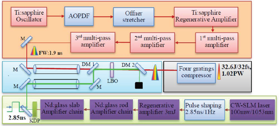
In contrast to the Russian OPCPA work, the SIOM has reported a 1-PW peak power system employing a large-aperture LBO crystal.27 The source, as shown in Figure B.15, employs a Ti:sapphire CPA system to provide a 800-nm-centered, 1.9-ns-duration chirped pulse with as much as 2.25 J of energy. A single OPCPA stage, employing a 100 x 100 mm-aperture, 17-mm-thick crystal, amplifies the CPA signal input to an energy of about 45 J, compressed to 32.6 J of energy with a 32-fs-duration pulse. A Nd:glass laser provides a 2.85-ns pump pulse in the green, in a 84-mm-diameter beam on the LBO crystal. In a series of optimization experiments, the best operating point was for a signal energy of 0.82 J and a pump energy of 170 J, for a 26 percent conversion of pump to chirped-pulse energy and a gain of 55. The conversion was at about 40 percent of the Manley-Rowe limit.
The SIOM work exploring combinations of signal input energy and pump pulse energy found issues with so-called “back conversion,” where energy in the signal and idler convert back to pump energy. In principle, with perfect phase-matching, spatially uniform pump and signal-input beams, and temporally uniform pump and signal pulses one could convert pump to signal energy up to the Manley-Rowe limit. In practice, none of these conditions can be met, especially phase-matching over a broad spectral range. Back conversion acts as a limit to the efficiency of OPCPA devices, and for the PEARL and SIOM the limit was in the range 36 to 40 percent of Manley-Rowe.
___________________
26 A.A. Shaykin, G.I. Freidman, S.G. Garanin, V.N. Ginzburg, E.V. Katin, A.I. Kedrov, E.A. Khazanov, et al., 2009, 1 petawatt OPCPA laser in Russia: status and expectations, in Lasers and Electro-Optics 2009 and the European Quantum Electronics Conference, June 14-19, Munich, CLEO Europe - EQEC.
27 L. Yu, X. Liang, L. Xu, W. Li, C. Peng, Z. Hu, C. Wang, et al., 2015. Optimization for high-energy and high-efficiency broadband optical parametric chirped-pulse amplification in LBO near 800 nm, Opt. Lett. 40(14): 3412-3415.
APPENDIX B3 ENABLING TECHNOLOGIES
Laser Diode Pumping Sources
Laser diodes are based on a semiconductor material with a p-n junction, where laser action is obtained by passing electrical current through the junction. First developed in the 1960s, they operated at room temperature as low-power continuous-wave (cw) devices (10’s of mW) until the 1980s, when advances in technology allowed power scaling of individual lasers to the 1 W level and fabrication of linear arrays (bars) to the tens-of-W level. Since then there have been steady advances to the point that single devices can operate at >10 W power levels and bars at the 500 W level. These power levels are not in a diffraction-limited laser beam but are nevertheless suited for many applications, notably optical pumping of solid-state lasers. Typical limits to power for single-emitter devices are destruction of the chip surface by optical damage, a limit that varies little whether the devices run cw or in a pulsed mode. For bars the limit is typically excessive temperature rise, and here the peak power available can be increased by running the device in a pulsed format.
The use of diodes for pumping of solid-state gain media has advantages over the use of gas-discharge lamps. Both can convert a high fraction of electrical power into light (60 to 80 percent),28 but diodes have the following advantages:
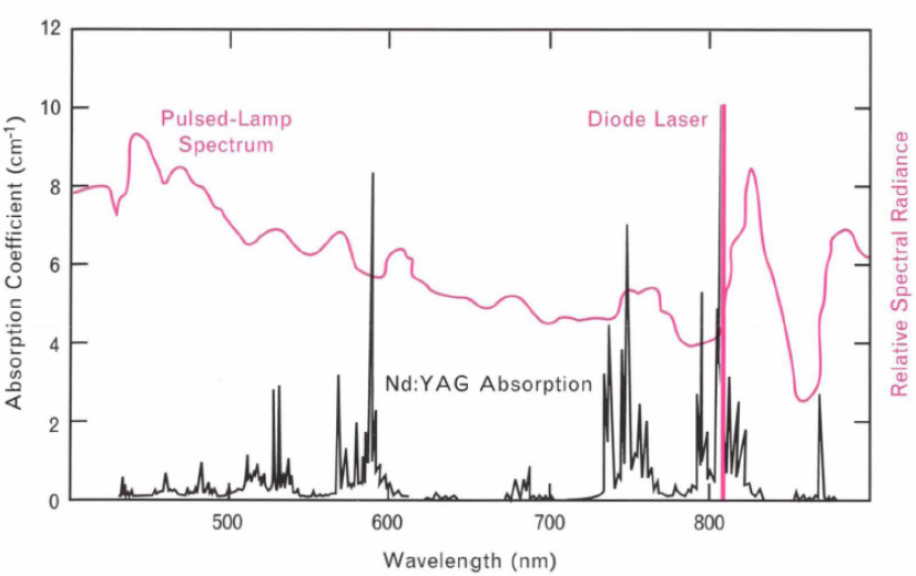
A narrow spectral bandwidth that can be tuned, by adjusting the composition of the semiconductor, to pump the upper laser level or slightly higher energy levels directly. This results in less heat left in the laser material compared to lamps, which, especially for near-infrared lasers, pump a multitude of higher-lying energy levels. In addition, lamps produce a large fraction of power that does not pump the laser material at all. Figure B.16 illustrates this for the case of Nd:YAG.
___________________
28 J. H. Goncz and P. B. Newell, “Spectra of Pulsed and Continuous Xenon Discharges,” J. Opt. Soc. Am. 56, 87 (1966). Data showed 65% conversion efficiency from electrical input to light in the 350- to 1100- nm region.; J. Holzrichter, Laser Fusion Program, Semiannual Report, July-December 1973, (UCRL-50021-73-2), Lawrence Livermore National Laboratory, University of California, Livermore, CA, p.44. Data was taken with a wavelength-insensitive calorimeter and a xenon flashlamp, showing as much as 80% conversion of electrical input to radiant energy; Commercial Diode bars operating in the 915-1030-nm wavelength region specify 62% conversion efficiency (II-VI Laser Enterprise BPC/OPC 80W), and 65% at 980 nm for unmounted bars (OSRAM SPL BF98-4-05); P. Crump, G. Erbert, H. Wenzel, C. Frevert, C. M. Schultz, K-H. Hasler, R. Staske, B. Sumpf, A. Maaßdorf, Frank Bugge, Steffen Knigge, and Gunther Trankle, “Efficient High-Power Laser Diodes,” IEEE. J. Sel. Topics Quantum Electron. 19, 1501211 (2013); P. A. Crump, M. Grimshaw, J. Wang, W. Dong, S. Zhang, S. Das, J. Farmer, M. DeVito, L. S. Meng, and J. K. Brasseur, “85% Power Conversion Efficiency 975-nm Broad Area Diode Lasers at – 50°C, 76 % at 10°C,” in Conference on Lasers and Electro-Optics/ Quantum Electronics and Laser Science Conference and Photonic Applications Systems Technologies, Technical Digest (CD) (Optical Society of America, 2006), paper JWB24.
A narrow spatial beam compared to the incoherent emission in all directions from a lamp, allowing better matching of the pump energy to the desired region in the solid-state gain medium, and thus higher conversion of pump power into laser power for some laser configurations.
The net result of the use of diodes is a much higher overall electrical efficiency for diode-pumped solid-state lasers, at least an order-of-magnitude, and, for a given power output, a much reduced level of waste heat in the laser material. For Nd:YAG, as an example, waste heat is one-third or less of that with lamps.29 The ability to deliver diode pump power to the desired gain region in a material is most significant at low powers, where excited volumes are small. For high-energy systems, especially large-aperture Nd:glass lasers, the brightness of diodes is less important, but the higher efficiency in converting electrical power to absorbed pump power, and the lower waste heat, remains an advantage for diodes.
___________________
29 T.S. Chen, V.L. Anderson, and O. Kahan, 1990, Measurements of heating and energy storage in diode-pumped Nd:YAG, IEEE J. Quantum Electron. 26(1): 6-8.
The replacement of cw arc-lamps and pulsed flashlamps by diodes has resulted in a major advance in solid-state laser systems, particularly for industrial applications. The major impediment for high-energy systems has been the cost of diode lasers compared to flashlamps. For example, a typical pulsewidth is about 0.2 ms for a pulsed pumping system with Nd-doped solid-state lasers. For 100 J of diode pump energy this requires a pump source with about 500 kW of peak power, or 1,000 bars with 500 W of power each. Even with diode cost at $1/W, the cost of lamps is still several orders-of-magnitude cheaper, even if at least 10x more energy is needed. Nevertheless, the improved performance with diode pumping can justify the extra expense. We discuss, below, current applications of diode pumping to high-peak-power lasers.
The emergence of high-power diodes has also enabled development of an entirely new class of solid-state lasers based on the rare-earth dopant ytterbium (Yb). The energy-level structure for this ion, which has only 1 electron in the 4f shell, is very simple compared to other rare earths. Referring to Figure B.17, for the case of Yb:YAG, there is only one main energy level above the ground state, with both absorption and emission taking place around 1,000 nm. Compared to Nd-doped crystals, the Yb-doped absorption and gain linewidths tend to be broader except for those between the lowest-lying ground state and lowest-lying excited state, the “zero-phonon” transition. This is the result of considerable lifetime broadening of the lower levels due to a high scattering rate by phonons. For flashlamp pumping the ion has poor absorption overlap with the broad emission spectrum of flashlamps, and lasers based on the ion did not find any commercial uses due to their low efficiency. This problem was eliminated with diode pumping, with the added advantage that the small difference in pump and laser wavelengths leads to a greatly reduced level of heating compared to 800-nm-region, diode-pumped Nd-doped lasers. As is evident from Figure B.17, absorption is present at the laser wavelength (making this a so-called 3½-level) laser, so the amount of pump power density needed to achieve gain is higher compared to Nd-doped lasers. This can be overcome with the high pump power densities possible with diode pumping or by cooling the laser material to reduce the population of the lower level and hence the absorption. We discuss more about Yb-doped media in sections below.
Thermal Management
For relatively low-energy (1-10 J/pulse), pulsed solid-state lasers with flashlamp pumping, active cooling, typically with flowing water, has long been used to allow modest average powers, in the 10-100-W range. Similar systems with diode pumping can run at much higher powers, at the kW level. With diodes as pump sources other overall systems designs are possible to better handle thermal issues with high cw or quasi-cw operation, notably the thin-disk laser first demonstrated

by Giesen30 and commercialized primarily by Trumpf Inc. (Ditzingen, Germany) and fiber-format lasers, which now can produce the highest cw powers of any commercial solid-state laser. Neither of these designs can operate with single apertures large enough for PW-class lasers, at least those with 10-fs and longer pulses.
For PW-level, high-energy systems, which have been, with the exception of BELLA, based on flashlamp-pumped Nd:glass, the pump laser has relied on passive air cooling for the laser material as well as the flashlamps. The firing of the next shot has to wait until components have returned to ambient temperature. This is
___________________
30 A. Giesen, H. Hugel, A. Voss, K. Wittig, U. Brauch, and H. Opower, 1994, Scalable concept for diode-pumped high-power solid-state lasers, Appl. Phys. B 58(5): 363-372.
also true of ICF drivers, but the OMEGA system does water-cool the lamps and thus can run at a higher shot rate than similar systems.31
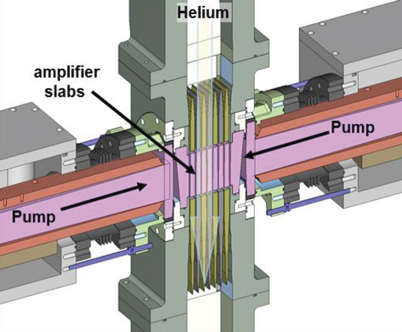
The challenge in more aggressive cooling of high-energy lasers arises from the large volumes of laser material needed for high-energy operation. Figure B.18 and Figure B.19 show two approaches used for large-aperture designs, involving flowing a coolant between a series of relatively thin disks of laser material. The first employs rapid flow of helium gas through the disks, which was demonstrated at
___________________
31 R. McCrory and C. Verdon, “Collaboration Ignites Laser Advances,” Lawrence Livermore National Laboratory, June 1999, https://str.llnl.gov/str/Verdon.html.
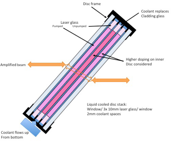
LLNL with the Mercury laser32 and is being used in the LLNL HAPLS Ti:sapphire laser, described in more detail below. Effective operation with the gas is aided in these by the lower heat loads from diode-laser pumping. Figure B.19 shows a design being tested by National Energetics, where liquid cooling (fluorinert) of the disks is employed in flashlamp-pumped systems and allows operation, for 250-J-class amplifiers, at rates of at least 0.1 Hz. Similar thin-disk designs can be used with Ti:sapphire lasers (see HAPLS, below), although liquid cooling is problematic due to the added spectral dispersion.
With future PW-level systems planned for operation at higher powers, considerations of thermal issues must also be applied to other elements of the system. With OPCPAs, in theory, there should be no heat deposited in the media, but in reality all materials have some level of optical absorption in the bulk of the crystal, as well as absorption due to defects in the surface polish and in the dielectric coatings. The issue is of concern since nonlinear materials in general do not have good thermo-mechanical properties. As an example, the thermal shock parameters of KD*P and BBO are 145 and 39 W/m, respectively, comparable to laser glasses.
___________________
32 A. Erlandson, 2014, “High Energy DPSSL Technology,” presented at the ELI-HiLASE Summer School, Aug. 24-29, Prague, Czech Republic, http://www.eli-beams.eu/wp-content/uploads/2013/11/Erlandson_high_energy_class_dpssl_technology.pdf.
Likely some form of gas-based cooling systems similar to that of Figure B.18 will be needed for high-average-power, high-energy OPCPAs.
Another area of concern for PW-class systems in the future is thermal limits to compression gratings. Present gratings employ metallic coatings, which have some level of absorptive losses. All-dielectric-coating gratings can be made but are challenged in operating over a wide enough bandwidth to compress 30-fs and shorter pulses. Research in this area, applied for example to the HAPLS system described below, is ongoing and proprietary in nature.
Fiber Geometry
One of the most significant recent developments in solid-state lasers has been the scaling in average power of fiber-geometry lasers, simply called fiber lasers. In general, fiber lasers involve an optical fiber that has a core doped with rare earths. The latter can be optically pumped to produce optical gain and thus laser action. The vast majority of fiber lasers employ silica glass as the major constituent of the fiber, with non-laser dopants such as Ge, Al, and F used to modify the index of the glass and create the index waveguide structures needed for light guiding. With proper control of the index structure in the fiber, one can constrain the beam properties of the fiber laser to a single, diffraction-limited mode, an important advantage for the fiber geometry. Two key developments have enabled power scaling of single-mode fiber lasers.
One is the concept of cladding pumping that allows highly divergent, multimode pump light to be coupled into the single-mode, doped core of an optical fiber.33 This allows the fiber laser to operate as a brightness converter, specifically taking the multi-mode power from a multitude of diode lasers and converting it into single-mode power. For fiber lasers doped with the rare-earth Yb, the raw optical power conversion from pump to output power can approach 90 percent.
Fibers are essentially rod-geometry solid-state lasers, where the limit on power output (independent of the rod diameter) is given by the fracture-limited heating power per unit length (W/l). This quantity is directly proportional to the thermal shock parameter of equation B.4. For fused silica, which has a very low thermal expansion coefficient, the thermal shock parameter (1,450 W/m) is similar to materials such as YAG, but more importantly, for typical cladding-pumped fiber lasers the length of material used in a laser is in the 120m range, about 1,000x that of typical rod lasers. Thermal fracture has not been an issue for conventional, silica-based fiber lasers.
___________________
33 E. Snitzer, H. Po, F. Hakimi, R. Tumminelli, and B. C. McCollum, 1988, Double clad, offset core Nd fiber laser, in Optical Fiber Sensors, Vol. 2, Optical Society of America, New Orleans.
The second development, mentioned above, has been the steady and significant improvement in the power available from diode lasers. Related to fiber lasers, an associated advance has been in finding ways to efficiently couple the outputs of many diodes into a single multimode fiber that in turn couples light into the cladding of the fiber laser. Present technology has allowed construction of directly diode-pumped fiber lasers that operate with a single fiber and a single mode (i.e., diffraction limited) at multi-kW power levels. Hybrid designs have also been developed that use a collection of lower-power fiber lasers to cladding pump the core of one fiber, and this has allowed further scaling of a single-mode fiber laser to the 10-kW level.34
Until recently, thermo-optic distortion of the core region of the fiber from temperature gradients created by laser operation has been small compared to the built-in refractive index structure in the fiber. Thus the beam properties of fiber lasers have been nearly power-independent. Advances in high-power diodes, and also in development of fibers with large single-mode core diameters, have shown that thermal effects can appear as a limit to single-mode power, especially when single-mode core diameters exceed about 15 µm. This effect, thermally induced mode instability (TMI),35 has become the most important limitation to the cw power available from single-mode fiber lasers. The commercial 10-kW fiber laser cited above mitigates TMI through the use of a small difference in pump and laser wavelengths, which minimizes fiber heating.
While the overall electrical efficiencies, high average power, and high beam quality of fiber lasers make them unique as solid-state lasers, the small diameter of the single-mode active core (on the order of 10-100 µm) limits the pulsed, peak-power outputs of individual fiber lasers. The ultimate limit is optical damage, but before that is reached, a variety of unwanted nonlinear optical effects distort the temporal and spectral nature of the pulse. In addition, although the gain-bandwidth of the most favorable fiber laser to date, Yb-doped silica glass (Yb:fiber), could support nominal 20-fs pulses, fiber lasers operate with high gain and are thus subject to substantial gain-narrowing, with the result that amplified pulsewidths for Yb:fibers are typically in the 200-fs and higher range. To date, the highest peak power output from a CPA-technology, single-Yb:fiber system is 3.8 GW (2.2 mJ in 415 fs),36 achieved through use of an extraordinary fiber having a 108- µm core diameter. In terms of average power, the highest achieved from a single-fiber CPA
___________________
34 V. Gapontsev, V. Fomin, and A. Yusim, 2009, Recent progress in scaling high-power fiber lasers at IPG photonics, in 22nd Annual Solid State and Diode Laser Technology Review, Newton, Mass, July.
35 A.V. Smith and J. J. Smith, 2011, Mode instability in high power fiber amplifiers, Opt. Express 19(11): 10180-10192.
36 T. Eidam, J. Rothhardt, F. Stutzki, F. Jansen, S. Hädrich, H. Carstens, C. Jauregui, J. Limpert, and A. Tünnermann, 2011, Fiber chirped-pulse amplification system emitting 3.8 GW peak power, Opt. Express 19(1): 255-260.
system is 830 W, for 640-ps pulses at a 78-MHz rate, or 12 MW of peak power.37 As we discuss in the next section, further energy scaling of ultrafast fiber lasers is possible through beam-combining techniques.
Beam Combination
When a limit to higher power output (or a shorter pulsewidth) is reached for a certain source technology, one can employ the use of multiple sources to exceed the limit. One extreme example is the NIF system at LLNL, which employs 192 different beams from Nd:glass lasers to irradiate the target. In this case, obtaining both a high energy and a uniform illumination are achieved by the combination of beams. However, to obtain higher focused intensities, this type of “incoherent” combination does not lead to higher beam brightness, i.e., the ability to put more power into a small focal area. For that, multiple sources must be coherently combined, either spatially to get higher brightness or spectrally to produce shorter pulses and hence higher peak powers.
Coherent combining of cw lasers requires precise control over the relative phases of the lasers so that the rapidly varying electric fields of the lasers all peak at the same time as well as overlap in space. This requires lasers to have a stable, single-frequency output as well as a spatial output with a well-defined phase-front and a well-defined polarization. Typical coherently combined lasers might consist of one low-power laser as a stable, singlefrequency source, which provides input to an array of amplifiers, the outputs of which are then combined. Given the need to maintain the correct phase relationship amongst the beams, one must hold the path length for light in each amplifier stable to a small fraction of the laser wavelength. Typically this can only be accomplished by an active, path-length control system for each beam. For a narrow-line, single-frequency source, the absolute path length for each amplifier does not have to match that of another amplifier, just the optical phases.
For coherent combining of pulsed lasers there is an added requirement. The absolute path lengths the pulses travel through the amplifiers must be matched enough so that the pulses all arrive at the same time, as well as with the same phase. Clearly, the path matching gets more challenging as the pulses get shorter. For example, a 30-fs pulse has a length in free space of 9 µm, and any path difference must be a small fraction of this for effective combining.
In the area of pulsed systems, one can also perform spectral combining, where lasers centered at different wavelengths can be combined to produce a broader--
___________________
37 T. Eidam, S. Hanf, E. Seise, T.V. Andersen, T. Gabler, C. Wirth, T. Schreiber, et al., 2010, Femtosecond fiber CPA system emitting 830 W average output power, Opt. Lett. 35(2): 94-96.
bandwidth source, with a shorter pulsewidth, again if the phases of the two lasers can be synchronized to the same degree required for spatial combining.
Much of the recent work in beam combining has involved cw fiber lasers, which can be engineered with both the beam and spectral properties needed for efficient coherent combining. Reported beam-combined results include total powers of 4 kW from 8 spatially overlapped (or “tiled aperture”) lasers38 and 5 kW from 4 lasers combined with a diffractive optic into one beam, so-called filled aperture combining.39 Both systems included an electronic control for the phase of each beam. In the former, feedback control for phase-locking employed the “stochastic parallel-gradient-descent” (SPGD) technique, an algorithm that seeks to maximize combined beam quality by continually dithering the phase of each laser40 until a desired metric, such as beam quality, is reached. The latter employed the “locking of optical coherence by single-detector frequency tagging” (LOCSET) scheme where each beam has a unique high-frequency phase modulation applied to then determine the needed phase correction for the beam.41
In terms of PW-class, intense-laser technology, coherent spatial and/or spectral combination techniques are more challenging. The present technology of Nd:glass-driven systems has such a low pulse rate that any adaptive feedback control for phase is impractical. It is unrealistic to expect that the optical phase path would remain stable enough against environmental changes between pulses to allow optimization of the beam or spectrum. We discuss newer technologies below for high-energy lasers that will allow higher pulse rates, but it remains an open question whether they can be high enough for effective combination.
There have been active efforts to explore beam combination of ultrashort-pulsed fiber lasers, given their high electrical efficiencies, high beam-quality, and high-average-power capabilities. The latter allow operation at high enough pulse rates to enable effective feedback control of beam and/or spectral combining. However, given the mJ-level of pulse energy now available from individual fibers, the absolute numbers of fiber lasers required to reach the PW-peak-power region goes well beyond the current state of the art. That has not prevented proposal of speculative schemes that scale fiber-based systems to the PW peak-power level. In the following we briefly discuss examples of these efforts, showing systems that
___________________
38 C.X. Yu, S. J. Augst, S. M. Redmond, K. C. Goldizen, D. V. Murphy, A. Sanchez, and T. Y. Fan, 2011, Coherent combining of a 4 kW, eight-element fiber amplifier array, Opt. Lett. 36(14): 2686-2688.
39 A. Flores, I. Dajani, R. Holten, T. Ehrenreich, and B. Anderson, 2016, Multi-kilowatt diffractive coherent combining of pseudorandom-modulated fiber amplifiers, Opt. Eng. 55(9): 096101.
40 M.A. Vorontsov and V. P. Sivokon, 1998, Stochastic parallel-gradient-descent technique for high-resolution wave-front phase-distortion correction, J. Opt. Soc. Am. A 15(10): 2745-2758.
41 T.M. Shay, 2006, Theory of electronically phased coherent beam combination without a reference beam, Optics Express 14(25): 12188-12195.
operate at the state of the art as well as designs that could allow scaling to large energy levels. A recent review of the subject provides more examples and details.42
There are two general schemes for spatial beam combining. One is similar to the approach used with cw lasers, where the outputs of multiple amplifiers working with the same input pulse are combined (common pulse). The other is unique to pulsed systems, where multiple pulses, separated in time, are combined into one pulse (divided pulses). The schemes can be combined for energy scaling, and we show how this had led to the highest peak power (35 GW) to date for a fiber-based system with eight fibers.43 We provide examples of these approaches below.
In this section we also discuss the use of an enhancement cavity at the output of a system to increase the peak power, which could be considered a form of beam combining.
Spatial—Common Pulse
22 GW of peak power has been obtained through the coherent combination of four very-large mode-area (80 µm) Yb:fiber lasers.44 An optical schematic of the system, Figure B.20 shows a CPA system, where a common, low-energy, stretched pulse is amplified, spectrally optimized by a spatial-light-modulator-based “Pulse-Shaper” (also seen in Figure B.7) and split into four beams through polarization-dependent, 50/50 beam splitters. Successive combining, two beams at a time, again with polarization-dependent optics, leads to a common beam that is then compressed. The phase-control scheme, based on a technique developed by Hänsch and Couillaud,45 senses the combined polarization of the two beams and adjusts the relative phases to maximize the linearly polarized combined power. The system construction took care to match the pulse propagation time for the four beam paths. Measurement of the compressed pulse indicated a 200-fs pulsewidth, with about 16 percent of the total pulse energy outside of the main pulse. The energy contained in the 200-fs pulse was about 5.7 mJ, and, at a 40-kHz rate, the average output power was 230 W.
It is important to recognize an important effect in this and other fiber-laser-based ultrafast systems. Despite the CPA technique, which for this system resulted
___________________
42 M. Hanna, M. Guichard, Y. Zaouter, D. N. Papadopoulos, F. Druon, and P. Georges, 2016, Coherent combination of ultrafast fiber amplifiers, J. Phys. B: At. Mol. Opt. Phys. 49(6): 062004.
43 Marco Kienel et al., “12 MJ KW-Class Ultrafast Fiber Laser System Using Multidimensional Coherent Pulse Addition,” Optics Letters 41, no. 14 (July 15, 2016): 3343–46, doi:10.1364/OL.41.003343.
44 A. Klenke, S. Hädrich, T. Eidam, J. Rothhardt, M. Kienel, S. Demmler, T. Gottschall, J. Limpert, and A. Tünnermann, 2014, 22 GW peak-power fiber chirped-pulse-amplification system, Opt. Lett. 39(24): 6875-6878.
45 T.W. Hänsch and B. Couillaud, 1980, Laser frequency stabilization by polarization spectroscopy of a reflecting reference cavit, Opt.Commun. 35(3): 441-444.

in 2-ns-duration pulses in the amplifiers, the nonlinear effect of the high peak power on the refractive index and hence the optical phase in the final amplifiers (self-phase modulation, or SPM) was significant, about 5 radians of shift, and thus the phase delay through the amplifiers depended strongly on the pulse peak power. This coupling of power and phase represents an added challenge to control of the beam-combining effectiveness, mapping intensity fluctuations to phase fluctua-
tions and adding to the other environmental perturbations on the phase of the beams to be combined.
Another combining scheme (XCAN), developed in collaboration between the Ecole Polytechnique and Thales in France, claims to be scalable to large numbers of fiber amplifiers.46Figure B.21 presents a schematic of the system, which remains at an early stage of actual implementation. The key features of the design are CPA, with pulses stretched to the several-ns length, a “tiled aperture” beam combination, and a camera-based sensor that samples each fiber output before compression, interfered with a common beam derived from the input to the fiber array. The image presented to the camera is a set of spatially distinct interference patterns that can be processed to derive the phase control for each fiber amplifier. The present plan seeks a short-term demonstration of a 61-fiber system with pulse energy of 10 mJ, with 50-kHz pulse rate, 350-fs pulses.
Spatial—Divided Pulse
One approach of the divided pulse amplification (DPA) scheme is to split a pulse into a series of replicas in time, not in space, and send them through a common amplifier. After that, one has to implement an inverse process to recombine the replicas into a single pulse. Here there is excellent spatial overlap, and the phase control shifts to that needed to ensure that the pulses recombine in time with the same phase. DPA can be considered as a variant of CPA in that the peak power of the split pulses is reduced, in this case by the number of replicas, and also that the maximum average power of the amplifier is not increased. The major challenge in DPA designs is in gain saturation in the common amplifier, where the gain for each subsequent pulse is smaller and thus the pulses do not match in amplitude (and for large saturation also shape) when they are recombined. This lowers the efficiency of the combination process. To avoid this and run the amplifier in a mode with minimal gain saturation unfortunately lowers the total energy extracted from the amplifier; for fibers, this reduces the overall electrical efficiency.
The DPA technique has been employed for ps-duration pulses, where temporal splitting is relatively simple, and can be done, for example, with a set of birefringent crystals, taking advantage of the stable optical path difference in the crystal for orthogonal polarizations.47 In the example cited, 32 pulse replicas of 2.2-ps
___________________
46 L. Daniault, S. Bellanger, J. Le Dortz, J. Bourderionnet, É. Lallier, C. Larat, M. Antier-Murge, J.-C. Chanteloup, A. Brignon, C. Simon-Boisson, and G. Mourou, 2015, XCAN – A coherent amplification network of femtosecond fiber chirped-pulse amplifiers, Eur. Phys. J. Special Topics 224(13): 2609-2613.
47 L.J. Kong, L. M. Zhao, S. Lefrancois, D. G. Ouzounov, C. X. Yang, and F. W. Wise, 2012, Generation of megawatt peak power picosecond pulses from a divided-pulse fiber amplifier, Opt. Lett. 37: 253.
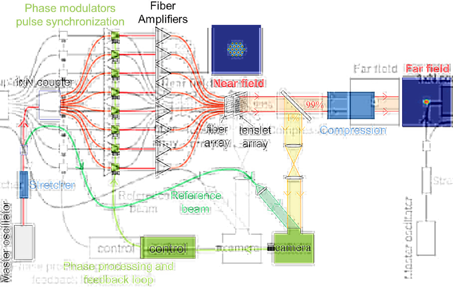
pulses were generated and amplified by Yb:fibers, and the design employed the same crystals to both split and recombine the pulses.
For high-energy scaling one needs to employs ns-duration chirped pulses, and here generation of replicas requires free-space optics, with m-level paths to produce enough delay between pulses. In one system separate splitting and combining optics were used to produce 4 pulses, with path-length control provided by a LOCSET control system, and individual control of pulse amplitudes in the optics provided some compensation for gain saturation in the Yb:fiber amplifier.48 The system generated 380-fs-duration compressed pulses of 1.25 mJ (2.9 GW) at a 30-kHz rate, with a recombination efficiency of 75 percent.
___________________
48 M. Kienel, A. Klenke, T. Eidam, S. Hädrich, J. Limpert, and A. Tünnermann, 2014, Energy scaling of femtosecond amplifiers using actively controlled divided-pulse amplification, Opt. Lett. 39: 1049.
A more sophisticated DPA scheme has been proposed but only demonstrated at low powers.49 In this design, the train of equally time-spaced pulses, to be amplified and then combined, is generated by an electronic system that controls both the amplitude and phase of each pulse. After amplification, the pulses are combined through use of mirror-based interferometers, specifically, a Gires-Tournois (GT) design. A set of pulses is injected into one interferometer, which has a round-trip time exactly equal to the pulse spacing. Pulse energies add together, and then a final (extraction) pulse is injected with a different phase but the same energy as that stored in the cavity and acts, through coherent interference, to couple all of the stored energy out in a single pulse. Through the combination of N of these interferometers, as shown in Figure B.22, it is possible to stack about 2N pulses together, with the understanding that the extraction pulse increases in energy as it passes through the N interferometers. By controlling the individual interferometer input/ output mirror reflectivities, it is possible to combine equal-amplitude pulses by control of just the pulse phase, simplifying the design.50 Another scheme, in Figure B.23, combines two sets of N interferometers, with the second set having a round-trip time 2N times as long as the first. This “multiplexing” scheme can combine about (2N)2 pulses. To date, researchers51 have stacked nine low-energy pulses by four cascaded GT interferometers with a pulse-energy increase of 7, and 16 dB of contrast between the main pulse and other pulses. In a multiplex design of four interferometers and one long-path interferometer, the same group combined 27 pulses.
This stacking design promises scaling to a large number of pulses and allows control of gain saturation in the amplifier through individual control of the pulse amplitude sent into the amplifier. A major challenge for future high-energy applications is in obtaining a sufficiently high pulse-contrast ratio.
Spatial—Combined Approaches
The highest pulse energy to date (12 mJ, before compression) from a fiber-laser-based, femtosecond-class source has been obtained through a combination of spatial and temporal beam combining.52Figure B.24 shows a schematic of the system, whose
___________________
49 T. Zhou, J. Ruppe, C. Zhu, I-Ning Hu, J. Nees, and A. Galvanauskas, 2015, Coherent pulse stacking amplification using low-finesse Gires-Tournois interferometers, Opt. Exp. 23 7442; J. Ruppe, M. Sheikhsofla, S. Chen, H. Pei, J. Nees, R. Wilcox, W. Leemans, and A. Galvanauskas, 2016, “Progress in Coherent Pulse Stacking: A Pathway Toward Compact kHz Repetition Rate LPA Drivers,” 17th Advanced Accelerator Concepts Workshop, Aug. 1-5, Gaylord National Resort, Baltimore. https://indico.syntek.org/event/4/session/15/contribution/234.
50 J. Ruppe, et al., 2016, “Progress in Coherent Pulse Stacking.”
51 J. Ruppe, et al., 2016, “Progress in Coherent Pulse Stacking.”
52 M. Kienel, M. Muller, A. Klenke, J. Limpert, and A. Tünnermann, 2016, 12 mJ kW-class ultrafast fiber laser system using multidimensional coherent pulse addition, Opt. Lett. 41(14): 3343-3346.
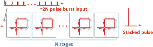
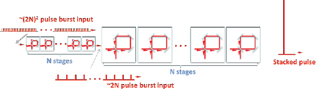
delay lines splits the 1.3-ns stretched pulse into 4 pulses, each of which is adjusted to correct for gain saturation in the final amplifiers. As with the system in Figure B.20, polarization optics spatially split the beam into 8 channels, which are then spatially recombined with polarization-based optics and then temporally combined with optical delay lines. For phase control the system combines HC and LOCSET control. The combined average power was 700 W and the estimated peak power after compression was 35 GW in a 262-fs pulse, to date the highest peak power from a fiber-based source.
Spectral
Spectral beam combining facilitates generation of shorter pulses than possible from a single type of source, whether a laser medium or an OPA. As with spatial combining, precision phase control of the combined sources is needed to generate a stable and reproducible pulse. When combined with high-energy amplification, the technique promises generation of PW-class peak powers for the lower pulse energies.

In pioneering low-energy work,53 pulses from a broad bandwidth Ti:sapphire mode-locked laser acted as seed sources for two OPCPAs. One, pumped by a
___________________
53 S.W. Huang, G. Cirmi, J. Moses, K-H. Hong, S. Bhardwaj, J. R. Birge, L-J. Chen, I. V. Kabakova, E. Li, B. J. Eggleton, G. Cerullo and F. X. Kartner, 2012, Optical waveform synthesizer and its application to high-harmonic generation, J. Phys. B: At. Mol. Opt. Phys. 45: 074009.
doubled Nd:YLF laser at 523 nm, provided amplification centered around 870 nm for input directly from the seed source. The other, pumped by the same laser at 1,047 nm, amplified a 2,150-nm-centered signal derived from difference-frequency generation with the Ti:sapphire pulse spectrum. When outputs of the two OPCPAs were coherently combined, they generated a complex pulse with an estimated duration of 0.8 cycles, centered at 1,260 nm, or approximately 3.3 fs in duration. A balanced optical cross correlator (BOC), the optical equivalent of a balanced microwave phase detector,54 provides the feedback signal needed to maintain a stable phase relationship between the pulses.
A more recent and ambitious attempt at spectral beam combining has been ongoing at the Max Planck Institute of Quantum Optics (MPQ) in Garching, Germany. An example of this concept,55 in Figure B.25, as part of “Third-generation femtosecond technology,” makes use of three OPCPAs pumped by the fundamental, second, and third harmonics of a Yb:YAG laser system. They are seeded by a three-octave spanning seed source based on a high-power Yb:YAG mode-locked laser combined with a variety of nonlinear pulse compression and spectral broadening techniques to produce a phase-coherent pulse with a spectrum from 450-2,700 nm. The three OPCPAs each amplify a different portion of this spectrum, and can, with proper control of phasing, be (theoretically) combined in output to generate pulses as short as 1.7 fs. The OPCPA pumps are derived from high-average-power, ps-duration thin-disk sources, developed initially for applications to industrial materials processing and could allow kHz-rates for pulses. At present, the efforts at MPQ are in the development phase to turn the concepts in Figure B.25 into a working reality.
With regard to fiber lasers, the Yb:fiber lasers, due to gain-narrowing, operate with CPA pulsewidths at least an order-of-magnitude higher than their gain linewidths could support. Dividing the input pulse spectrum into several spectral regions can allow Yb:fiber lasers to produce shorter pulses. In one low-power demonstration,56 a broadband input source was split into two spectral bands, which peaked at 1,026 and 1,040 nm, and each was input to a Yb:fiber CPA and then combined, with phase control on one beam provided to lock the phases. Here the interference between the two beams provided a sensing signal through high-frequency modulation of the phase. The combined pulsewidth was 130 fs.
___________________
54 T.R. Schibli, J. Kim, O. Kuzucu, J. T. Gopinath, S. N. Tandon, G. S. Petrich, L. A. Kolodziejski, J. G. Fujimoto, E. P. Ippen, and F. X. Kaertner, 2003, Attosecond active synchronization of passively mode-locked lasers by balanced cross correlation, Opt. Lett. 28(11): 947-949.
55 H. Fattahi, H. Barros, M. Gorjan, T. Nubbemeyer, B. Alsaif, C. Teisset, M. Schultze, et al., 2014, Third-generation femtosecond technology, Optica 1(1): 45-63.
56 F. Guichard, M. Hanna, L. Lombard, Y. Zaouter, C. Hönninger, F. Morin, F. Druon, E. Mottay, and P. Georges, 2013, Two-channel pulse synthesis to overcome gain narrowing in femtosecond fiber amplifiers, Opt. Lett. 38(24): 5430-5433.
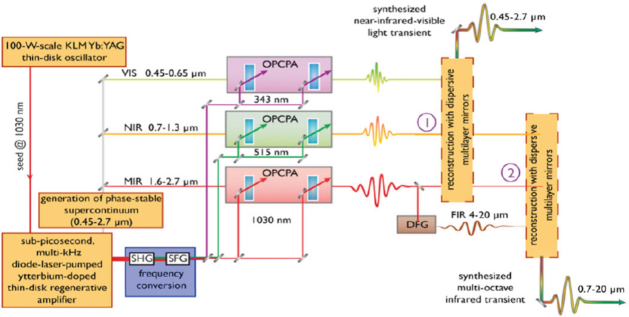
External Cavity Peak Power Enhancement
Pulses repetitively injected into an external, low-loss resonator, if synchronized with the resonator round-trip time, can build up in peak power through additive combination, or “pulse stacking,” which can be viewed as a variation on the technique of divided pulse amplification. For fiber lasers, pulse stacking allows the device to operate with relatively low-energy pulses at a high pulse rate—a favorable operating condition for this technology. The key to extraction of the enhanced-power pulse for use outside of the resonator is the insertion of a fast, low-loss optical switch inside the resonator that diverts the pulse out in a time short compared to the cavity round-trip time. A recent theoretical design57 postulated a stacking of 666 pulses to enable scaling of one spatially combined, 16-channel CPA (0.18 mJ per pulse per amplifier) running at a 10 MHz pulse rate to an energy of 1.3 J/pulse at 15 kHz. With compression of the resultant pulse to 300 fs, the peak power could be 3 TW. The key technology to be developed is the required fast and low-loss optical switch inside the resonator that could handle such a high pulse energy/power.
___________________
57 S. Breitkopf, T. Eidam, A. Klenke, L. von Grafenstein, H. Carstens, S. Holzberger, E. Fill, et al., 2014, A concept for multiterawatt fibre lasers based on coherent pulse stacking in passive cavities, Light: Science & Applications 3: e211.
Pulse Compression
A variety of pulse-compression techniques are under investigation, particularly for fiber lasers, which, even with CPA techniques, are challenged to produce pulses shorter than 100 fs. Many of these compression schemes, employing solid-core fibers, gas-filled hollow-core photonic-crystal fibers, or gas-filled capillary tubes, involve a nonlinear process, such as self-phase-modulation, to add additional bandwidth and frequency chirp to the pulse, combined with spectral dispersion that compresses the pulse to a smaller pulsewidth than at the input. All do lead to some loss of pulse energy. In general, these schemes do not have the aperture needed to reach or even approach the PW regime, with the exception of the thin-film compressor we reference below. We describe several potentially large-aperture techniques that are under deployment, development, or consideration.
Tiled Gratings
The desire to further scale the energy of intense-laser sources creates a challenge for fabrication of the large-area gratings (e.g., Figure 2.2) needed to avoid optical damage in the grating-based compressor stages of CPA systems. One approach to reach larger energies is to use multiple (tiled) gratings, essentially a form of coherent spatial beam combination. The technique requires the same level of alignment, path-length, and phase control applied to coherent beam-combining. In this case the control requirements are somewhat easier, as one does not have to contend with the large path lengths and environmental changes present in amplifier systems. In principle, the feedback system control system can function effectively even with low-pulse-rate sources. Figure B.26 shows the mechanical design of one three-grating tiled compressor system58 that is equivalent, in theory, to a 1.41-m aperture grating. Two of the gratings have a linear position control as well as tip, tilt, and rotation controls that assemblers can adjust, using laser-based, interferometic measurements to achieve suitable alignment of all three gratings.
Raman Compressors
Plasma-based compressors were proposed59 in 1999 as an alternative to gratings for pulse compression and as a means to reach multi-MJ, exawatt (1018 W) pulses needed for applications such as fast-igniter fusion. A plasma is gas-like state
___________________
58 J. Qiao, A. Kalb, M. J. Guardalben, G. King, D. Canning, and J. H. Kelly, 2007, Large-aperture grating tiling by interferometry for petawatt chirped-pulse–amplification systems, Opt. Exp. 23(15): 9562-9574.
59 V.M. Malkin, G. Shvets, and N. J. Fisch, 1999, Fast compression of laser beams to highly overcritical powers, Phys. Rev. Lett. 82: 4448.
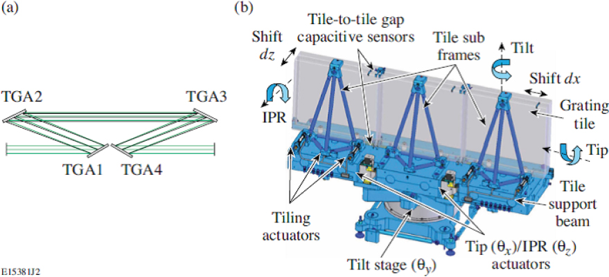
of matter consisting of free electrons and an equal number of positively charged ions, which can be sustained by applying a suitable electric field to a cell containing a gas. In principle, plasmas can survive source intensities higher than solid materials, particularly gratings. The most promising plasma-based compressor scheme uses stimulated plasma Raman scattering, which is a type of parametric process similar to OPAs. Here the interaction involved is with light and longitudinal electronic oscillations in the plasma. The oscillations arise from the restoring force between ions and electrons when the incoming light acts to separate the equilibrium locations of electrons and ions and create spatial regions that have a net charge. In the Raman process, light at a (signal) frequency equal to the difference between that of a “pump” source and that of the electron plasma oscillation frequency can be amplified.
Figure B.27 shows a conceptual timing diagram of a plasma Raman compressor. In the top of the figure, a high-energy, long-pulse pump beam, moving from left to right in the plasma, encounters a low-energy, short-duration seed pulse at the signal frequency, moving in the opposite direction. The bottom of the figure represents a later point in time when the amplified seed pulse becomes large enough in energy to remove a large fraction of the pump energy, essentially compressing a portion of the pulse energy into roughly the same duration as that of the seed.
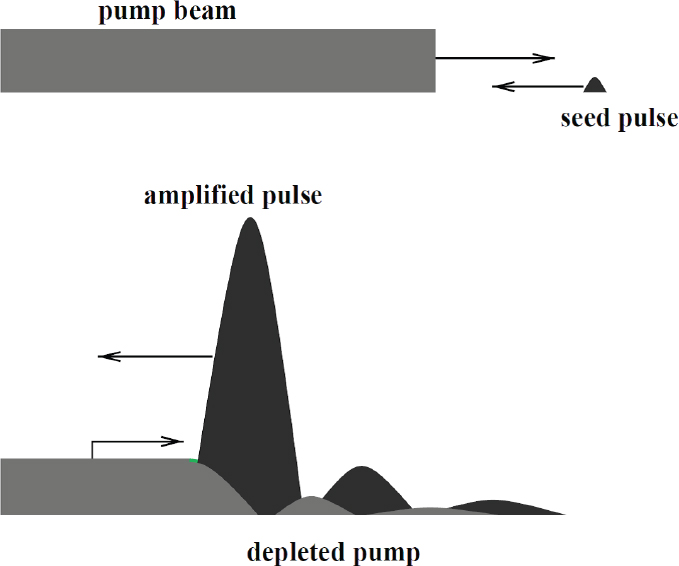
While the fundamental concept of Raman pulse compression is simple, modeling of all of the nonlinear interactions in the plasma is highly complex and computer intensive. While some work has investigated 1,000x compression of ps-duration pulses to the fs level, other studies claim that ns-duration pulses can be similarly compressed, with 60 percent efficiency, into the ps regime.60 Since the initial proposal, extensive research efforts (primarily theoretical) have identified a variety of processes that complicate efficient compression61 and recent models suggest that the parameter space for efficient compression is narrow.62 The latter
___________________
60 R. M. G. M. Trines, F. Fiúza, R. Bingham, R. A. Fonseca, L. O. Silva, R. A. Cairns, and P. A. Norreys, 2011, Production of picosecond, kilojoule, and petawatt laser pulses via Raman amplification of nanosecond pulses, Phys. Rev Lett. 107(10): 105002.
61 V.M. Malkin, Z. Toroker, and N. J. Fisch, 2014, Exceeding the leading spike intensity and fluence limits in backward Raman amplifiers, Phys. Rev. E 90(6): 063110.
62 R. M. G. M. Trines, F. Fiúza, R. Bingham, R. A. Fonseca, L. O. Silva, R. A. Cairns, and P. A. Norreys, 2011, Simulations of efficient Raman amplification into the multipetawatt regime, Nature Physics 7: 87-92.
work proposed a system that would compress a 25-ps pulse at 800 nm to about 25 fs, with 35 percent efficiency. To date, laboratory efforts63 have led to generation of 60 GW of peak power in a 50 fs pulse, with a 20-ps pump and low (6.4 percent) conversion efficiencies. Work at the Laboratory for Laser Energetics is planned to explore much higher energy and power regimes64 with a high-energy, Nd:glass, ps-duration pump laser at 1,053 nm.
One area of interest for this technology is in the compression of shorter-wavelength sources, where damage-resistant gratings are not available, but here the work to date has been in theory only.
Thin-Film Compressors
A more speculative compressor, in this case to take 25-fs-duration pulses into the 2-fs regime, has been proposed65 based on the use of thin plastic films. The system schematic in Figure B.28 shows a two-stage design, with a 25-fs pulse passing through a 0.5-mm plastic film (Film1), where self-phase-modulation in the film adds bandwidth and frequency chirp to the pulse. The pulse is then reflected by two mirrors, with deformable surfaces to correct for beam irregularities due to both the input beam and the plastic film, and compressed by a chirped-mirror compressor (Compressor 1) to about 5 fs. The compressed pulse passes through another plastic film, 0.1 mm in thickness, and a similar mirror-compressor scheme to reduce the pulsewidth to about 2 fs.
The proposed design modeled a 27 J, 27 fs (1 PW), 800-nm Ti:sapphire laser with a uniform output beam and a beam diameter of 16 cm. The use of a plastic film allows an inexpensive means of deploying such a thin material over a large diameter. With an assumed efficiency of >50 percent, the compressor achieves a peak power increase of nearly 10x, and the design can be employed with higher-peak-power lasers through suitable area scaling.
___________________
63 J. Ren, W. Cheng, S. Li, and S. Suckewer, 2007, A new method for generating ultraintense and ultrashort laser pulses, Nature Phys. 3:732-736.
64 J. Bromage, University of Rochester, “Ultra-High Intensity Laser Technology,” presentation to the committee on July 14, 2016.
65 G. Mourou, S. Mironov, E. Khazanov, and A. Sergeev, 2014, Single cycle thin film compressor opening the door to Zeptosecond-Exawatt physics, Eur. Phys. J. Spec. Top. 223(6): 1181-1188.

APPENDIX B4 SYSTEMS UNDER CONSTRUCTION OR CONSIDERATION
We organize this section by the technologies being utilized.
Nd:glass
Extreme Light Infrastructure Beamlines, 10 Petawatts
The ELI Beamlines facility in Prague, Czech Republic has ordered a 10-PW-power Nd:glass system, with delivery planned for the end of 2017, from National Energetics in Austin, TX, a spinout company related to the “Texas Petawatt” system described above. The technology is similar in that a mixed-glass high-energy amplifier is combined with an OPCPA front end. In contrast with the earlier system, active cooling of the Nd:glass elements, as illustrated in Figure B.19 in Appendix B3, is part of the design, allowing for a claimed pulse rate of one per minute.
Figure B.29 is a functional block diagram of the system, showing the staging and details of the energetics and pulse/spectral properties, and Figure B.30 is an optical schematic of the design. The goal is to generate 150-fs-duration pulses
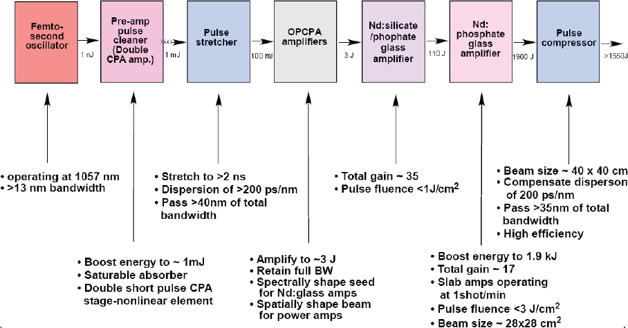

and > 1,500 J of compressed energy. The final amplifiers will operate with 30-cm aperture, phosphate Nd:glass slabs.
Laser Ignition Fusion Energy, Lawrence Livermore National Laboratory
LLNL, in considering the future of laser-driven ICF, carried out a design study for a laser capable of driving a fusion-based electrical power plant. We provide some of the study details as they provide guidance on what could be the basis for future designs for Nd:glass lasers and OPCPA systems operating with high rates at the PW level. The designs also have been employed on a smaller scale for the pump laser used in the HAPLS Ti:sapphire laser described below.
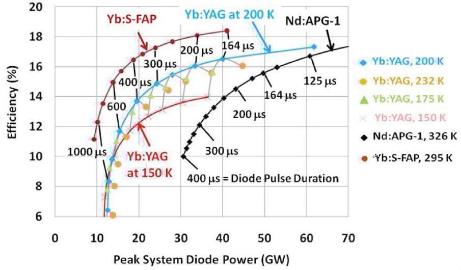
The laser requirements for Laser Ignition Fusion Energy (LIFE) called for a megajoule-class, ns-pulse laser that would operate at a pulse rate of 16 Hz. The design concept was based on high-efficiency modules, each operating at 130 kW (8 kJ/pulse) of average power at the fundamental wavelength. As part of the study, researchers66 did a system overall electrical efficiency trade-off among several diode-pumped solid-state media, with the results plotted in Figure B.31. The efficiency calculations included the power consumed for cooling in systems operating below ambient temperature. The net result was that Nd:glass could operate with an efficiency comparable to crystalline media. The medium has the advantage that it has been well developed and is available in large sizes, in contrast to Yb:SFAP and, to a lesser extent, Yb:YAG.
___________________
66 A.C. Erlandson, S. M. Aceves, A. J. Bayramian, A. L. Bullington, R. J. Beach, C. D. Boley, J. A. Caird, et al., 2011, Comparison of Nd:phosphate glass, Yb:YAG and Yb:S-FAP laser beamlines for laser inertial fusion energy (LIFE), Opt. Mat. Exp. 1(7): 1341-1352.
Ti:sapphire
High-Repetition-Rate Advanced Petawatt Laser System, Extreme Light Infrastructure Beamlines
As with National Energetics, LLNL is under contract to design, build, and deliver a PW-class laser system to the ELI Beamlines facility. The High-Repetition-Rate Advanced Petawatt Laser System (HAPLS) is based on a 1-PW, Ti:sapphire laser pumped by a 10-Hz, diode-pumped Nd:glass laser, with a design building on prior work at LLNL on high-pulse-rate, high-energy diode-pumped lasers, including the LIFE design discussed above. A rendition of the system appears in Figure B.32 and includes a Nd:glass pump laser with the capability for 200 J/pulse of fundamental energy. A key component of the system is an 800-kW pulsed, 888-nm-wavelength diode-laser array, shown in Figure B.33, developed by Lasertel Inc. (Tucson, AZ) and driven by LLNL-developed pulse-power electronics,67 that provide 300-µs-duration pulses with 75 percent efficiency in delivering electrical power to the diodes. For some perspective, the array is claimed to be the largest peak-power diode-laser system ever developed. Four of these arrays are used, for a total maximum pump energy of 960 J. The Nd:glass slabs are cooled by the flowing He-gas design in Figure B.18, with a similar design used for the Ti:sapphire crystals. The planned operating point for 1 PW of compressed peak power (30 J in 30 fs) is 42 J of energy from the Ti:sapphire laser with 107 J of green pump energy and 140 J of fundamental pump energy. At 10 Hz the system would operate the Ti:sapphire laser at the highest average power ever attained from the material.
As of December 2016, the system had operated with the pump laser at an intermediate milestone of >100 J of fundamental energy, 75 percent conversion to the second harmonic, and operation of the Ti:sapphire source with < 30 fs pulsewidth.68
High Field-Petawatt, Extreme Light Infrastructure-Attosecond Pulse Light Source
In contrast to the HAPLS system, the ELI-ALPS facility in Szeged, Hungary was scheduled to obtain a 10Hz, 2PW Ti:sapphire laser that employs flashlamp-pumped pump lasers, for the so-called HF PW System.69 A schematic of the system appears in Figure B.34. The device, to be built by Amplitude Technologies (Lisses, France)
___________________
67 E.S. Fulkerson, S. Telford, R. Deri, A. Bayramian, R. Lanning, E. Koh, K. Charron, and C. Haefner, 2015, Pulsed power system for the HAPLS Diode Pumped Laser System, in Proceedings of the IEEE Pulsed Power Conference (PPC), Austin, May 31-June 1.
68 Lawrence Livermore National Laboratory, “Petawatt Laser System Passes a Key Milestone,” January 22, 2016, https://www.llnl.gov/news/petawatt-laser-system-passes-key-miestone.
69 K. Osvay, 2015, “The ELI attosecond light pulse source,” http://www.eli-alps.hu/sites/default/files/tangows/20150224-0945-ELI-ELIALPS-General-KarolyOsvay.pdf.
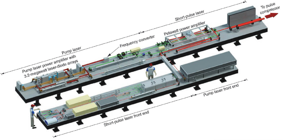
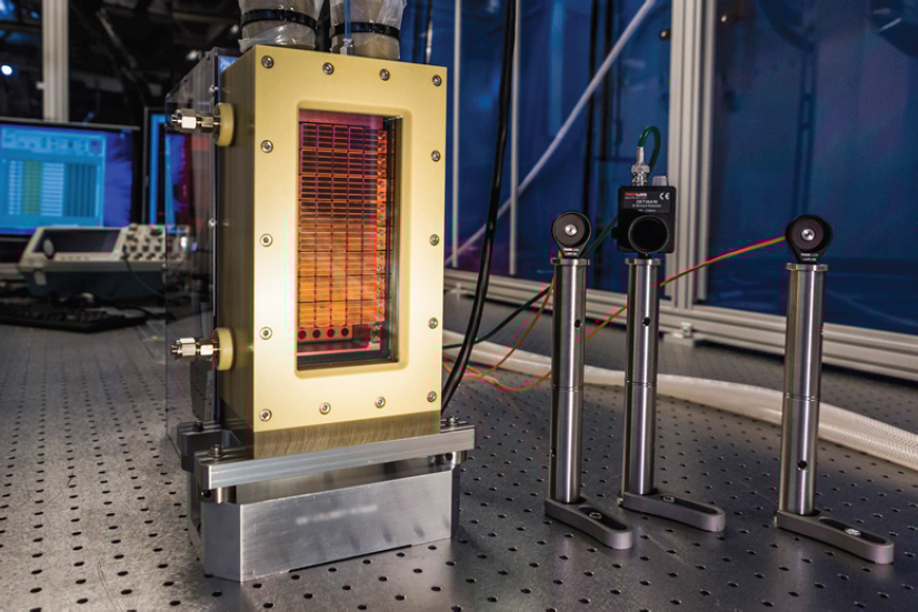
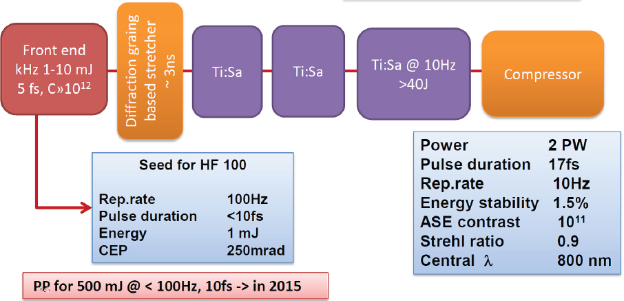
in cooperation with their subsidiary, Continuum (San Jose, CA), would include newly designed pump lasers providing 60 J of energy from a single beam.70 Also in contrast with the HAPLS system, the design would seek to operate with 17-fs-duration pulses, thus requiring 34 J of pulse energy, compared to the 30 J design for the LLNL system. The front end of the system would be based on a high-contrast, OPCPA design.
In a recent update on the HF-PW system,71 it now appears that the specifications of the final stages of the HF-PW system are uncertain, with one possibility being a Ti:sapphire system providing 40 J in < 15 fs pulses at a 5-Hz rate, or an OPCPA system at 10 J in < 8 fs at a 10-Hz-rate, but “the parametric super-fluorescence contrast and substantial level of laser command control has to be yet demonstrated for PW OPA stages.”72
___________________
70 P.M. Paul, F. Falcoz, E. Gontier, S. Branly, L. Vigroux, and G. Riboulet, 2016, Towards high repetition rate ultra-intense lasers, latest developments at Amplitude Technologies, in Proceedings High-Brightness Sources and Light-Driven Interactions, Long Beach, California, March 20-22, Optical Society of America.
71 Extreme Light Infrastructure, “ELI-ALPS Research Facilities,” http://www.eli-alps.hu/?q=en/02_ Parameters, accessed January 27, 2017.
72 Extreme Light Infrastructure, “ELI-ALPS Research Facilities.”
Center for Relativistic Laser Science, Korea
At the Center for Relativistic Laser Science (CoReLS) in Gwangju, Korea, a 4-PW Ti:Sapphire has recently been operated at a 0.1 Hz pulse rate.73 The system is an upgrade to a 1.5 PW source at the facility, with an added Ti:sapphire “booster” amplifier pumped by 180 J/pulse (green), Nd:glass-based system, delivering 112 J of energy with a 34-J input, for an efficiency of 47 percent. To narrow the system pulsewidth, developers employed a spectrally optimized OPCPA-based seed laser and were able to obtain a compressed pulsewidth of 19.6 fs, with 83 J of energy. The system is in the commissioning stage and is slated to become available for experiments in the near term.
Extreme Light Infrastructure-Nuclear Physics, 10 Petawatts, Romania
At the ELI-NP facility in Magurele, Romania, Thales Optronique (Elancourt, France) is currently set to install two 10-PW Ti:sapphire systems, pumped by a bank of flashlamp-pumped Nd:glass lasers operating at 1 pulse/minute. A schematic of the combined systems appears in Figure B.35, including additional, higher-pulse-rate beamlines for other experiments. The system front-end design appears in Figure B.36, showing a hybrid scheme with a Ti:sapphire mode-locked oscillator and CPA stages, followed by a compressor, XPW stage, another stretcher, to the 20-ps level, and a high-gain OPCPA stage pumped by pump source whose pulse is derived from the Ti:sapphire oscillator.74 The front end produces 10.5-mJ, 20-ps pulses at a 10-Hz rate, with a pulse contrast of 1012 in a 100-ps window around the main pulse and a bandwidth of 70 nm. This output is stretched to the ns level and injected into a series of Ti:sapphire amplifiers, shown in Figure B.35, to reach the final design energy of 280 J, which yields a projected compressed energy of 210 J in 21 fs.
The initial high-energy Ti:sapphire amplifier stages utilize flashlamp-pumped Nd:YAG lasers similar to those used in the BELLA system described above. The final Nd:glass amplifiers are pumped by as many as eight “ATLAS” 100J (527-nm) Nd:glass lasers. Figure B.37 shows a photograph of one completed ATLAS system, while Figure B.38 shows a drawing of the complete system as it will be installed at ELINP. The ELI-NP 10 PW laser is scheduled for operational status in 2018.
___________________
73 S.K. Lee, J. H. Sung, H. W. Lee, J. Y. Yoo, and C. H. Nam, 2016, “0.1 Hz Sub-20 fs 4 PW Ti:Sapphire Laser,” presented at Seminar 4, Annual International Laser Physics Workshop, Yerevan, Armenia, July 11-15, http://www.lasphys.com/workshops/abstracts/files/2016/99/ff/0c/fef86f98c626380d3544758d06/abstract.pdf.
74 F. Lureau, 2015, “High Power Laser System (HPLS),” in ELI-NP Science Program and Instruments Technical Design Reports, Magurele, Romania, February 18-20, http://www.eli-np.ro/indico/getFile.py/access?contribId=2&resId=0&materialId=slides&confId=22.
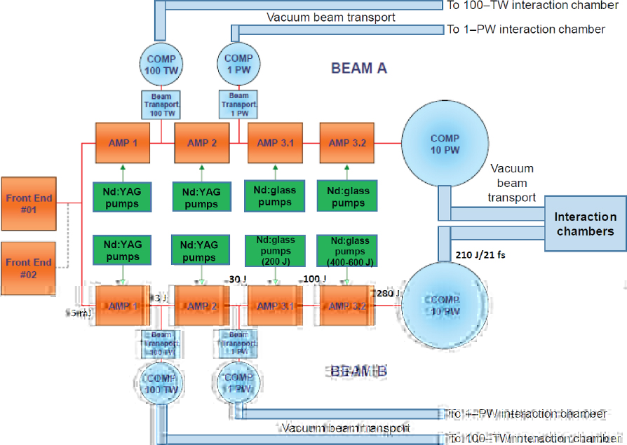
APOLLON, France
The Apollon laser, under construction at l’Orme des Merisiers, Saclay, France, is also slated to generate 10 PW of peak power, but as of September 2015 was funded for 5 PW.75 The design pulsewidth of 15 fs is slightly shorter than the 21-fs pulse for the ELI-NP system. Figure B.39 shows a diagram of the Apollon front end. As with the ELI-NP system an OPCPA design is employed to amplify the output of the Ti:sapphire mode-locked source, but in this case a 1,030-nm part of the oscillator spectrum is amplified in a Yb:fiber, stretched to 1.5 ns, amplified to 2 mJ
___________________
75 Ecole Polytechnique, “Birth of Apollon, the most powerful laser worldwide,” September 30, 2015, https://www.polytechnique.edu/en/content/birth-apollon-most-powerful-laser-worldwide?language=en.
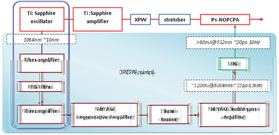
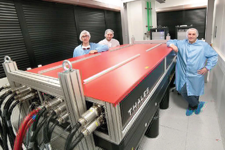
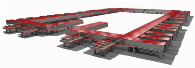
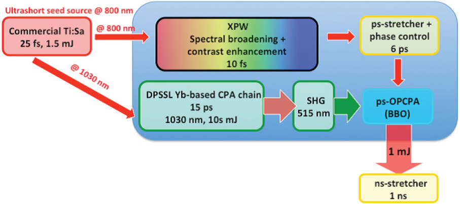
in a Yb:KYW regenerative amplifier and further amplified in a Yb:YAG thin-disk regenerative amplifier to 150 mJ. The 15 ps compressed pulse is doubled to about 80 mJ of energy and pumps a BBO OPCPA. A Ti:sapphire CPA system after the oscillator provides 1.5 mJ, 25-fs pulses which drive a XPW stage to provide high contrast (> 1013), the output of that is stretched to 6 ps and provides the input
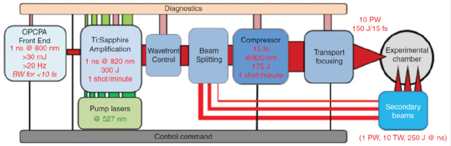
to the OPCPA stage.76 The mJ-level OPCPA output pulse is then set to amplified further to provide an input to the high-energy Ti:sapphire amplifier chain.77 The use of diode-pumping for all of the lasers in the front-end enables a 100-Hz pulse rate, an aid to the use of diagnostics and feedback controls that provide for a high-stability seed source, even when the entire system runs at a much lower rate.
Figure B.40 shows the entire system block diagram, indicating that the OPCPA front end will provide 30mJ, 1-ns-duration pulses with a theoretical bandwidth supporting <10fs pulses, although the overall system is designed for 15 fs compressed pulses. The Nd:glass, liquid-cooled pump lasers, built by Continuum and National Energetics, will run at a rate of 1/minute and are specified to generate a total of 800 J of green energy for the final three stages of Ti:sapphire amplifiers. The last amplifier will utilize 17.5-cm-diameter Ti:sapphire crystals, with a pumped diameter of 15 cm. Compression gratings for the system, supplied by LLNL, measure 91 × 45.5 cm.
At present, the Apollon laser is scheduled to be available for experiments in 2018.
___________________
76 D.N. Papadopoulos, P. Ramirez, A. Pellegrina, N. Lebas, C. Leblanc, G. Chériaux, J. P. Zou, et al., 2015, “High-contrast 10-fs OPCPA-based Front-End for the Apollon-10PW laser,” paper ATu4A.3 in Advanced Solid State Lasers, OSA Technical Digest.
77 J.P. Zou, C. Le Blanc, D.N. Papadopoulos, G. Chériaux, P. Georges, G. Mennerat, F. Druon, et al., 2015, Design and current progress of the Apollon 10 PW project, High Power Laser Science and Engineering 3:e2.
10 Petawatts at the Shanghai Institute for Optics and Fine Mechanics
Presently under consideration at the Shanghai Institute for Optics and Fine Mechanics (SIOM) is a 10-PW source that employs a Ti:sapphire stage as the final amplifier.78 The device would be installed at the Superintense Ultrafast Laser Facility (SULF) at SIOM. The notional design would utilize two 527-nm, 500-J, 10 ns pump beams from Nd:glass lasers, arranged to provide four separate time-delayed pumps in a design similar to that in Figure B.11. The amplifier would provide a gain of 10 and generate about 500 J of energy with a 1.5-ns pulse before compression. Based on the 5.3-PW laser now at SIOM, the system pulsewidth would be about 24 fs, requiring a minimum of 240 J of compressed energy to reach the 10-PW level. The major issue to be resolved is whether the required gain and stored energy can be achieved before parasitic losses arise in the amplifier.
Optical Parametric Chirped-Pulse Amplifiers
10 Petawatts at the Shanghai Institute for Optics and Fine Mechanics
Also under consideration at the Shanghai Institute for Optics and Fine Mechanics (SIOM) is a 10-PW source that would employ an OPCPA stage as the final amplifier, also for use in SULF at SIOM. Figure B.41 is a diagram of the system design, which employs a Ti:sapphire-based source, similar to the SIOM 2- and 5.3-PW systems described above, to reach the 50-J energy level. In order to achieve the 10-PW output power, two materials are under investigation for the final 800-nm-region OPCPA stage, LBO and YCOB. (KD*P does not have a high-enough bandwidth for operation in this wavelength range.) The ultimate choice may depend on the ability to grow either material with a sufficiently large aperture to handle the 2-kJ, 527-nm pump beam derived from a Nd:glass laser. The system projected optical-optical efficiency of 25 percent will yield a 500-J pulse, compressed to produce a 300-J, 30-fs output pulse. Issues to be resolved before this choice would be made, besides obtaining the OPCPA crystal, are whether the desired OPCPA efficiency can be realized.
Vulcan 20 Petawatts, UK
The Central Laser Facility (CLF) at the Rutherford Appleton Laboratory, in Oxford, UK, has had several high-peak-power systems in operation, including a flashlamp-pumped Nd:glass laser (Vulcan) with a CPA option that can generate
___________________
78 R. Li, L. Yu, Z. Gan, C. Wang, S. Li, Y. Liu, X. Liang, et al., 2016, “Development of a Super Intense Laser Facility at Shanghai,” presentation at IZEST Conference Extreme Light Scientific and SocioEconomic Outlook, Paris, Nov. 25-29.
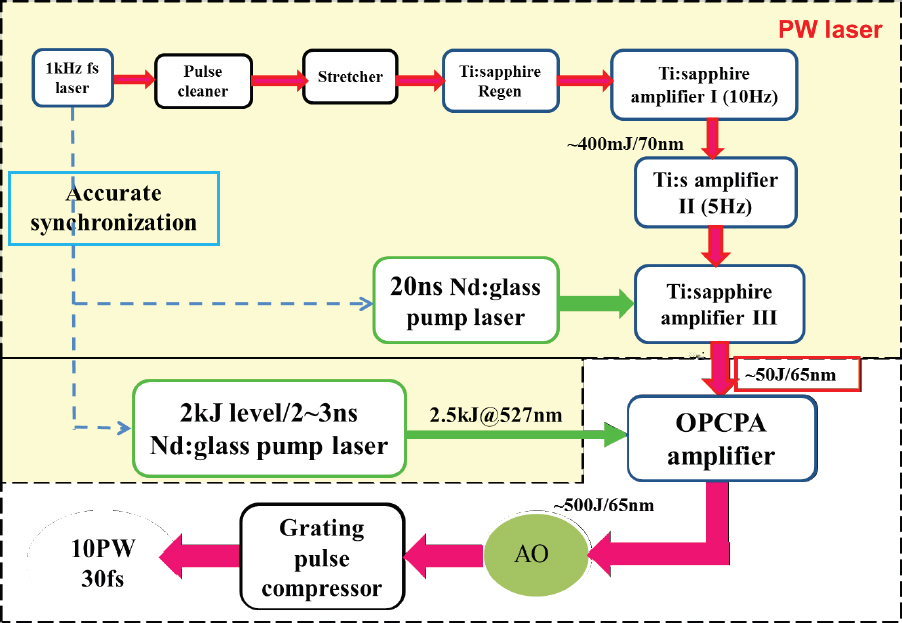
1 PW (500 J in 500 ps) at a pulse rate of 1 shot every 20 minutes.79 Of interest to the CPA option is the early and pioneering use of OPCPA technology to provide the front end for the system. The CLF also has a Nd:glass-pumped Ti:sapphire laser (Gemini) that has two output beams, each capable of 15 J in 30fs pulse (0.5 PW) at a pulse rate of one shot every 20 seconds.
For over a decade the CLF has been engaged in the development of an OPCPA-based source that would utilize the Vulcan laser as a pump source. The initial effort was intended to generate 10 PW of peak power, as diagrammed in Figure B.42, and was able to demonstrate the front end of the system, up to the Joule-level with ns pulses. Budgetary constraints put development on hold around 2008. Current plans are under way to eventually reach the 20-PW level.
___________________
79 C.N. Danson, P.A. Brummitt, R.J. Clarke, J.L. Collier, B. Fell, A.J. Frackiewicz, S. Hawkes, et al., 2005, Vulcan petawatt—design, operation and interactions at 5 × 10²⁰ Wcm−2, Laser Part. Beams 23: 87–93.
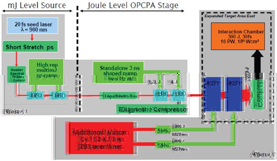
The design of the system involves the use of large-aperture KD*P crystals, which, when pumped by a doubled Nd:glass laser, have maximum spectral bandwidth when non-collinear phase-matching is set for a central wavelength of 910 nm (see Figure B.12 and Figure B.45). This is the same technology discussed above for the Russian PW-class OPCPA systems. In order to provide a seed laser at this wavelength, researchers at the CLF developed a unique, Ti:sapphire-pumped, collinear-phase-matched OPCPA-based source80 that employs a chirped pump (around 400 nm) and synchronized chirped signal (around 714 nm) to maintain phase-matching over a broad wavelength region and generate an idler beam at 910 nm with a bandwidth of > 165 nm, suitable for compression to 15 fs. More recent work has shown how the chirping scheme can be optimized to generate an optimized 910-nm source, stretched to 3 ns and capable of compression to below 20 fs after the final OPCPA amplifier.81
___________________
80 Y. Tang, I. N. Ross, C. Hernandez-Gomez, G. H. C. New, I. Musgrave, O. V. Chekhlov, P. Matousek, and J. L. Collier, 2008, Optical parametric chirped-pulse amplification source suitable for seeding high-energy systems, Opt. Lett. 33(20): 2386-2388.
81 A.S. Wyatt, P. Oliveira, A. Boyle, Y. Tang, M. Galimberti, I. N. Ross, I. O. Musgrave, C. Hernandez, and J. Collier, 2015, “Ultra-Broadband Spectral Phase Control in the Vulcan 20PW Upgrade Front End,” in 2015 European Conference on Lasers and Electro-Optics, Munich, June 21-25, Optical Society of America.
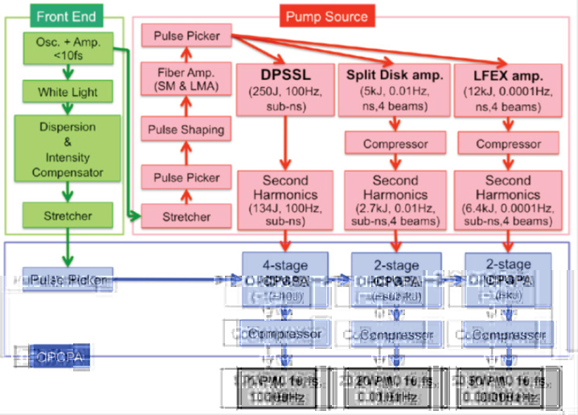
1, 20, and 50 Petwatts Gekko-EXA
Since 2009 a group at the Institute of Laser Engineering (ILE), Osaka University, Japan has been discussing development of a high-peak power OPCPA system, with initial discussions suggesting a two-beam source with a total peak power of 200 PW. More recently, a design for a 50-PW, single-beam system has been proposed, along with additional beamlines that generate 1 PW, 10-fs pulses at 100 Hz and 20 PW, 10-fs pulses at 0.01 Hz.82 The overall design appears in Figure B.43, and shows a common front end generating < 10-fs pulses, followed by associated low-energy stretchers and amplifiers to provide the signal (center wavelength around 1,053 nm) for the OPCPAs as well as the seed sources for the OPCPA pumps. The 100-Hz-pump system employs diode-pumped, cryogenically cooled Yb:YAG crys-
___________________
82 J. Kawanaka, K. Tsubakimoto, H. Yoshida, K. Fujioka, Y. Fujimoto, S. Tokita, T. Jitsuno, N. Miyanaga, and Gekko-EXA Design Team, 2016, Conceptual design of sub-exa-watt system by using optical parametric chirped pulse amplification, Journal of Physics: Conference Series 688:012044.
tals, while the 0.01-Hz system may use either Nd:YAG or Nd:glass, with a split-disk cooling design similar to that in Figure B.19. The 50-PW beamline employs the existing Nd:glass-based Laser for Fast Ignition Experiments (LFEX) at the ILE. In all cases, the final OPCPA stages are based on partially deuterated KDP (p-DKDP) crystals, arranged for slightly non-collinear phase-matching to provide 600-nm gain bandwidths around 1,053 nm.
75-Petawatt Extended Performance-Optical Parametric Amplifier Line, Laboratory for Laser Energetics
LLE has presented a conceptual design to build an OPCPA-based 75-PW source (EP-OPAL) that would be pumped by the OMEGA EP Nd:glass laser.83 The latter system, in operation since 2008, has 4 beamlines, each with technology derived the LLNL NIF laser. Each beamline, operating with a 10-ns pulse, can produce 6.5 kJ of 351-nm energy. Two of the beamlines can also run with short pulses, with 2.6 kJ of 10-ps-pulsewidth energy at the fundamental, and up to 1 PW of peak power, 1 kJ of energy with a 1-ps pulsewidth. The system shot rate is one per 105 minutes.84
Figure B.44 is an optical schematic of the proposed EP-OPAL system, which shows that two of the OMEGA-EP beamlines would be employed to provide doubled (527-nm) wavelength pump energy of 6.3 kJ in a 2.5ns pulse. The final NOPA (really non-collinear OPCPA) stages would employ large-aperture KD*P crystals, in common with the Russian PW OPCPA systems and the proposed Vulcan 20 PW system, discussed above. We show the calculated gain as a function of wavelength for that material in Figure B.45.
LLE has been engaged in preliminary work on a sub-scale system, MTW-OPAL, to test out some of the technologies, and plans to demonstrate that device by 2019, with a goal of 7.5 J in 15 fs.85 To date, LLE has developed and has operational a high-contrast, ultra-broadband front end (UFE) for the system, the design of which appears in Figure B.46.86 The source is unique in that the short pulse, providing a broad linewidth in the 810-1010-nm region, is derived from a “white-light continuum” (WLC) which is generated by a fiber-laser pumped crystal. The WLC is
___________________
83 J. Bromage, University of Rochester, “Ultra-High Intensity Laser Technology,” presentation to the committee on July 14, 2016.
84 S. Morse, “Omega Laser Facility and User Group Overview,” presentation to the committee on July 14, 2016.
85 J. Bromage, 2016, “Ultra-High Intensity Laser Technology.”
86 E.M. Campbell, 2015, “Ultrahigh Brightness Laser Development at the Laboratory for Laser Energetics,” presentation at George Washington University, Washington, D.C., December 14. https://physics.columbian.gwu.edu/sites/physics.columbian.gwu.edu/files/downloads/Campbell_LDRS2015.pdf.

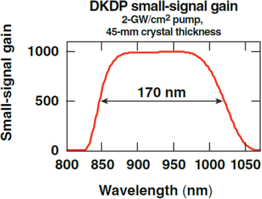
___________________
87 J. Bromage, 2016, “Ultra-High Intensity Laser Technology.”
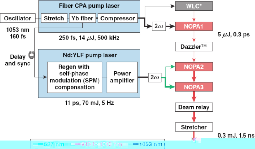
subsequently amplified by three picosecond-pulsewidth-pumped NOPAs and then stretched to a 1.5-ns pulsewidth for further amplification by OPCPAs. The use of the relatively low-pulse-rate WLC makes possible a high pulse-contrast ratio compared to a mode-locked source, where the high pulse rate can make suppression of nearby (in time) pulses a challenge.
Operation of the eventual EP-OPAL system requires solving a number of technological challenges, including development of gratings with both a large bandwidth and aperture, sufficiently large KD*P crystals, wavefront control for high beam quality, and optical coatings needed to handle the large bandwidths and high peak energies.87
Exawatt Center for Extreme Light Studies, 200 Petawatts, Russia
During the initial stages of planning for what is now the Extreme Light Infrastructure (ELI), presently under construction in Europe at three locations, there was a proposal to develop a “Fourth Pillar” facility in Russia that would include a laser system generating 200 PW of peak power. The program, Exawatt Center for Extreme Light Studies Project (XCELS) proposed to reach this level through the coherent combination of 12 Nd:glass-pumped, KD*P, OPCPA-based sources, as shown in Figure B.47.88 The bases for the system were energy-scaled versions of the Russian OPCPAs discussed above, “PEARL” and “Luch.” For XCELS a 500-J, 1-ns-stretched pulse source would be split in 12 beams and each beam would be then amplified back to the 500-J level, compressed to 400 J in 25 fs and then coherently combined at the target. As we have noted, such coherent combination would present a major control challenge given the expected low pulse rate of the system. The future status of XCELS is uncertain given a variety of monetary and political challenges.
Shanghai Institute for Optics and Fine Mechanics, 100 Petawatts
We note that recently the SIOM has proposed to build a 100-PW source (1,500 J in 15 fs), presumably OPCPA-based, as part of a facility called the Station of Extreme Light Science (SEL) at X-ray FEL, where the possibility of combining the source with an X-ray FEL will provide a unique experimental capability.89
Yb-doped Materials
As discussed in Appendix B3, the development of diode pumping opened a variety of new approaches to the operation of solid-state lasers and a whole class of laser materials based on the rare-earth dopant Yb. With relation to PW-class lasers, a direct system similar to Nd:glass or Ti:sapphire is a challenge, as an examination of Table 2.1 indicates. While Yb-doped, large-bandwidth materials have favorable storage times, extraction of the stored energy faces the problem of a relatively high saturation fluence, especially for materials with a large bandwidth. The use of multi-passing to overcome the high fluence then makes short-pulse operation problematic, due to gain narrowing.
___________________
88 A.G. Litvak, E.A. Khazanov, and A.M. Sergeev, 2013, Exawatt Center for Extreme Light Studies Project (XCELS), https://gargantua.polytechnique.fr/siatel-web/linkto/mICYYYSJkYY6.
89 R. Li, L. Yu, Z. Gan, C. Wang, S. Li, Y. Liu, X. Liang, et al., 2016, “Development of a Super Intense Laser Facility at Shanghai,” presentation at IZEST Conference Extreme Light Scientific and SocioEconomic Outlook, Paris, Nov. 25-29.
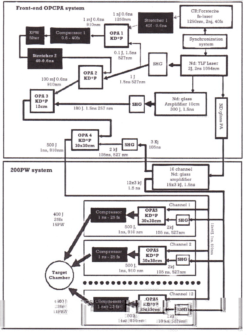
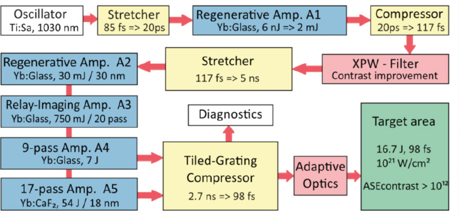
We discuss below two systems under construction that are attempting to reach PW levels directly from the diode-pumped Yb-doped media. We follow with descriptions of high-energy Yb-doped ns-duration lasers, which can be employed as pumps for OPCPA (or Ti:sapphire) systems as an alternative to Nd doped lasers.
POLARIS (glass)
The POLARIS (Petawatt Optical Laser Amplifier for Radiation Intensive Experiments) in operation at the Helmholtz Institute in Jena, Germany, employs a mix of diode-pumped Yb:glass and Yb:CaF2 media as amplifiers.90 The Yb:glass media are used for all but the final stage of the system because of their large gain bandwidth, but this does lead to a limited pulse rate of 0.02 Hz even with diode pumping. A schematic of the system, in Figure B.48, shows a double-CPA design, where pulses from a mode-locked Ti:sapphire laser at 1,030 nm are stretched to 20 ps, regeneratively amplified, compressed, and then passed through an XPW stage
___________________
90 M. Hornung, H. Liebetrau, S. Keppler, A. Kessler, M. Hellwing, F. Schorcht, G. A. Becker, M. Reuter, J. Polz, J. Körner, J. Hein, and M. C. Kaluza, 2016, 54 J pulses with 18 nm bandwidth from a diode-pumped chirped-pulse amplification laser system, Opt. Lett. 41(22): 5413-5416.
for contrast enhancement. After that, the pulses are stretched to the ns region and passed through a series of regenerative and multi-pass amplifiers, with the final stage a 17-pass, Yb:CaF2 amplifier that generates 54 J of energy. This stage employs a 6.5-cm-diameter, 3.4-cm thick crystal and is pumped by 1.2 kJ (120 diode arrays) of diode energy at 940 nm, delivered in a 4-ms-duration pulse. The extracted energy represents an optical efficiency of 4.5 percent. Due to the limited aperture of the available compression gratings, only a fraction of the pulse energy has been compressed, yielding a 16.7 J, 98fs, pulse, or 0.17 PW. Future system improvements may yield peak powers closer to the PW level. The system pulse contrast from background ASE is estimated to be 7 × 10¹³.
PENELOPE (CaF2)
Under construction at the Helmholtz-Centre Dresden-Rossendorf (HZDR) in Germany is the PEnELOPE (Petawatt, Energy-Efficient Laser for Optical Plasma Experiments) system.91 The staging of the system is diagrammed in Figure B.49 and shows a series of regenerative and multipass amplifiers, with roughly a 10x increase in energy between stages. The 60-fs, diode-pumped Yb:KGW oscillator pulse is stretched to 3 ns, with a 50-nm bandwidth, and followed by thin-disk (active-mirror) amplifiers to the 1-J level. The final two, 12-pass stages employ He-gas-cooled disks (4 per stage) with sizes of 5.5 and 11 cm, respectively, cooled to the 200-300 K range, and operate with diode pulsewidths in the 1.5-4-ms region. Thus the final stage of the system, with 1.2 MW of diode peak pump power, will utilize a pump energy of 1.8-5 kJ, leading to optical efficiencies well below 10 percent. Operation at the 0.1-PW level (15 J in 150 fs) at a 10-Hz rate is scheduled for 2016, while the PW-level system at 10x the energy and a 1-Hz rate is planned for 2017.92
High-Energy, ns-pulse Yb:YAG Lasers
High-energy, ns-pulse, diode-pumped Yb:YAG lasers can provide an alternative to various Nd-doped lasers as pumps for both Ti:sapphire lasers and OPCPAs. In Figure B.31 we show an efficiency comparison for a particular ns-pulse application, MJ-energy driving of ICF, that shows favorable operation for Yb:YAG lasers with
___________________
91 M. Siebold, F. Roeser, M. Loeser, D. Albach, and U. Schramm, 2013, “PEnELOPE - a high peak-power diode-pumped laser system for laser-plasma experiments,” in High-Power, High-Energy, and High-Intensity Laser Technology; and Research Using Extreme Light: Entering New Frontiers with Petawatt-Class Lasers, (J. Hein, G. Korn, L.O. Silva, eds.), Proc. of SPIE Vol. 8780, 878005; Helmholtz-Zentrum Dresden-Rossendorf, “PEnELOPE,” February 6, 2016, https://www.hzdr.de/db/Cms?pNid=2098.
92 P. Michel, 2016, ELBE Center for High-Power Radiation Sources, Journal of Large-Scale Research Facilities 2: A39.
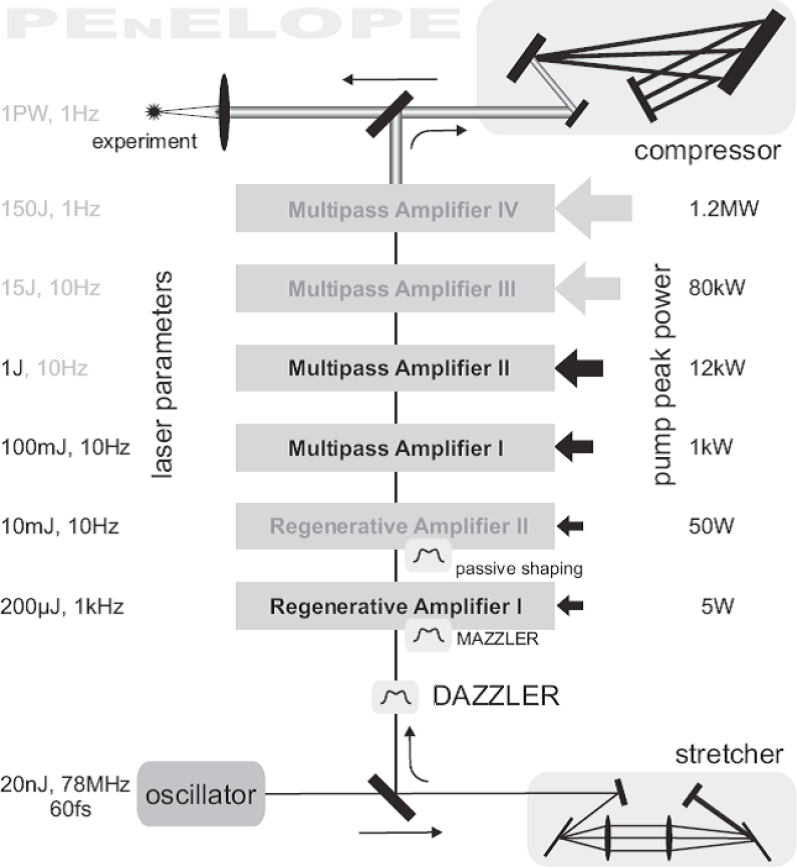
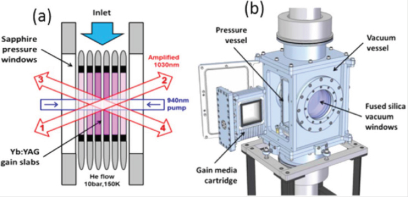
cooling to below room temperature, and indicates that the diode-peak power (and hence cost) to reach a certain energy would be less than for Nd:glass. For more modest energies the requirements for large-diameter Yb:YAG crystals is relaxed to levels now attained through ceramic fabrication techniques.
The Diode Pumped Optical Laser for Experiments (DiPOLE) system under development at the CLF, Rutherford Laboratory,93 intended for eventual application in the L2 Beamline at ELI Beamlines in Prague, utilizes a He-gas-cooled final stage based on ceramic Yb:YAG. Figure B.50 shows the details of this stage, which contains six, 0.85-cm thick, square-shaped ceramic gain media slabs, with a central 10cm square, Yb-doped YAG region surrounded by a 1-cm-wide, Cr-doped YAG absorptive cladding for ASE suppression. To date, with gas cooling at 175 K, the system has generated a 10-ns output pulse with 107 J of energy. The pulse rate was limited to 1 Hz by issues with the cooling system, but the goal is 10Hz operation, and cooling to 150 K. The two 940-nm diode pump source produced a total of 506 J in a 1.2-ms-pulse, for an optical efficiency of 21 percent.
In principal, as an OPCPA pump (doubled), the DiPOLE laser could be the basis for an overall PW-class system, with a 20-J, 20-fs pulse output from the OPCPA.
___________________
93 S. Banerjee, P. D. Mason, K. Ertel, P. J. Phillips, M. De Vido, O. Chekhlov, M. Divoky, et al., 2016, 100 J-level nanosecond pulsed diode pumped solid state laser, Opt. Lett. 41(9): 2089-2092.
In other, similar work, Hamamatsu Photonics K.K., in Shizuoka, Japan, has reported on a 55 J, cryogenically cooled (105 K) Yb:YAG laser with 55 J of pulse energy at a low rate. The diode-pump produced 450 J of energy in a 1 ms pulse and produced an estimated stored energy of 170 J. Further development of this system is under way, for both scientific and industrial applications.94
As a reminder, we note from above the intent at the ILE in Japan to construct a 1-PW (10 J in 10 fs) OPCPA-based source running at 100 Hz, based on a 250-J/pulse, cryogenically cooled, ns-pulse, diode-pumped Yb:YAG laser, doubled to 134 J/pulse and driving a multi-stage OPCPA to produce the desired peak power.
Fiber Geometry
International Coherent Amplification Network
The International Coherent Amplification Network (ICAN) was a highly publicized conceptual design for a Yb:fiber-based, PW-class system. Motivated by a desire to drive next-generation particle accelerators, the ICAN design (Figure B.51) called, in one publication,95 for a 30-J/pulse, 30-fs output at kHz rates, but a later publication discussed goals of >10 J per pulse, a >10 kHz pulse rate with pulses of 100–200 fs duration.96 The longer pulsewidth in the later publication recognizes that, with the properties of Yb:fibers, a 30-fs pulse would require spectral beam combination in addition to spatial combination. Given the notional design of 1 mJ/fiber, the system requires > 10,000 fiber lasers to meet the output-energy requirements.
There are several major challenges for the ICAN concept, which are evident from our discussion, in Appendix B3, of experimental results to date with fiber lasers.
The number of required lasers is several orders of magnitude beyond the number of sources that have been coherently combined to date. This issue can be mitigated by cascading the combining process (i.e., combine 10 lasers, then combine the combined laser, etc.) but it still represents a major control challenge.
For pulsewidths in the 100-fs range, the path lengths for all the fibers require matching at the 30-µm level.
Even at the mJ level for a chirped pulse, for conventional fibers there is a strong coupling, due to nonlinear optical effects, between the phase delay in the
___________________
94 T. Sekine, Y. Takeuchi, T. Kurita, Y. Hatano, Y. Muramatsu, Y. Mizuta, Y. Kabeya, Y. Tamaoki, and Y. Kato, 2016, “High Gain, High Efficiency Cryogenic Yb:YAG Ceramics Amplifier for Several Hundred Joules DPSSL,” in Lasers Congress 2016, Optical Society of America.
95 T. Tajima, W. Brocklesby, and G. Mourou, 2013, ICAN: The next laser powerhouse, Optics & Photonics News 24(5): 36-43.
96 G. Mourou, W. Brocklesby, T. Tajima, and J. Limpert, 2013, The future is fibre accelerators, Nature Photonics 7: 258-261.
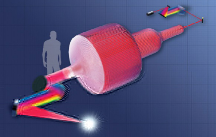
fiber and the pulse intensity, adding in the need to match and control the energy out of each fiber.
Obtaining a high pulse contrast is problematic, as ASE is a major issue with fiber lasers and there is no evident technique in ICAN to suppress ASE to the levels required by many applications.
At present, development of the ICAN concept has evolved into the XCAN effort discussed above.
Free-Electron Lasers
While we have considered PW-level laser-based sources for generation of high intensities, another approach to reaching high intensities is to greatly shorten the wavelength of the source to allow much tighter focusing and enable high intensities without requiring PW-level powers. Free-electron lasers can provide a source of short-wavelength (e.g., X-rays), coherent radiation, and in addition could produce significantly shorter pulses than conventional lasers. To date, they have produced pulses on the order of 10 fs, with pulse energies on the order of 1 mJ, and focal spot sizes on the order of 100 nm. These numbers imply a combined peak power of 1021 W/cm2.
SASE-driven X-ray Free-Electron Lasers
FELs were originally conceived as broadly tunable lasers in the infrared and visible97 but came into their own with the realization that they could operate
___________________
97 L.R. Elias, M. Fairbank, J. M. J. Madey, H. A. Schwettman, and T. I. Smith, 1976, Observation of stimulated emission of radiation by relativistic electrons in a spatially periodic transverse magnetic field, Phys. Rev. Lett. 36: 717.
as ultra-high power X-ray laser sources without requiring mirrors or a stable recirculating optical cavity. This principle, known as self-amplified stimulated emission (SASE),98 comes about because the relativistic electron gain medium travels along with the radiation it produces. Therefore the lasing requirement for a long gain-length product, which is ordinarily achieved by recirculating the light with mirrors, can instead be accomplished without mirrors by simple linear co-propagation of the light and the electrons. SASE led to the development of today’s class of uniquely valuable, high-powered, X-ray free-electron laser light sources such as the U.S. Department of Energy’s LCLS, first commissioned at SLAC.99 Current-generation FELs have approximately one billion times higher power than the synchrotrons they replaced, and thus are far and away the most intense X-ray laser sources available. These currently operate at photon energies up to about 10 keV, with peak power up to 50 GW, demonstrated focused intensities of 1020W/cm2,100 and pulse lengths from 100 fs down to less than 1 fs. They have led to some unique science, including science in high-intensity areas that will be discussed later in this report. (See Tables B.2 and B.3)
The general characteristics of X-ray pulses can be summarized as follows:
- Pulse energy hundreds of μJ to a few mJ.
- Linewidth in SASE mode about 10−3, order of magnitude of the FEL parameter ρ, about 10 times smaller than SASE when using self-seeding.
- Pulse duration from a few to about 100 fs.
- About 103 photons/electron, at 1 Å, compared to about 10−2 for spontaneous radiation, more at longer wavelengths.
Free Electron Laser Basic Concepts and Technology
Free-electron lasers use relativistic electrons as a gain medium. Their principle of operation is resonant stimulated synchrotron radiation by electrons that are wiggling in a periodical magnetic field array called an undulator, as shown in Figure B.52.101 The resonant wavelength is equal to the slippage length between
___________________
98 R. Bonifacio, C. Pellegrini, and L. M. Narducci, 1984, Collective instabilities and high-gain regime in a free electron laser, Opt. Commun. 50: 373.
99 P. Emma, R. Akre, J. Arthur, R. Bionta, C. Bostedt, J. Bozek, A. Brachmann, et al., 2010, First lasing and operation of an angstrom-wavelength free-electron laser, Nature Photonics 4(9): 641–647.
100 H. Mimura, H. Yumoto, S. Matsuyama, T. Koyama, K. Tono, Y. Inubushi, T. Togashi, et al., 2014, Generation of 1020 W cm−2 hard x-ray laser pulses with two-stage reflective focusing system, Nature Communications 5: 3539.
101 J.M.J. Madey, 1971, Stimulated emission of Bremsstrahlung in a periodic magnetic field, J. Appl. Phys. 42: 1906-1913; C. Pellegrini, A. Marinelli, and S. Reiche, 2016, The physics of x-ray free-electron lasers, Rev. Mod. Phys. 88(1): 15006.
TABLE B.2 Characteristics of Hard X-ray Free-Electron Laser in Operation or under Construction (identified by the *)
| LCLS | SACLA | European X-FEL* | Korean-X-FEL* | Swiss X-FEL* | LCLS-II Cu RF* | |
|---|---|---|---|---|---|---|
| Electron energy (GeV) | 2.15–15.9 | 5.2–8.45 | 8.5–17.5 | 4–10 | 2.1–5.8 | 2.5–15 |
| Wavelength range (nm) | 0.11–4.4 | 0.275–0.063 | 5.1–0.04 | 0.6–0.1 | 7–0.1 | 1.2–0.05 |
| X-ray pulse energy (mJ) | 1–3 for 0.1<λ<1.5 | 0.2–0.4 for 0.08<λ<0.275 | 0.67–8.5 for 0.04<λ<5.1 | 0.81–1 for 0.1<λ<0.6 nm | 0.5–1.3 for 0.1<λ<7 | 1–4.5 for 0.05<λ<0.4 |
| Pulse duration, rms (fs) | 5–250 for 0.1<λ<1.5 | 4.3 for 0.08<λ<0.275 | 1.68–107 for 0.04<λ<5.1 | 8.6–26 for 0.1,λ<0.6 nm | 2–20 for 0.1<λ<7 | 5–50 |
| Linewidth, rms (%) SASE | 0.5–0.1 for 0.1<λ<1.5 | 0.11–0.37 for 0.08<λ<0.275 | 0.02–0.25 for 0.04<λ<5.1 | 0.15–0.18 for 0.1<λ<0.6 nm | 0.06–0.4 for 0.1<λ<7 | 0.2–0.1 |
| Linewidth, rms (%) seeded | 0.01–0.005 for 0.1<λ<1.5 | 0.01–0.03* 0.08<λ<0.275 | 0.04–0.005 for 0.04<λ<5.1 | 0.002–0.002 for 0.1<λ<0.6 nm | 0.01–0.002 for 0.1<λ<7 | 0.02 |
TABLE B.3 Characteristics of Soft X-ray Free-Electron Lasers Operating and under Construction
| FLASH | Fermi FEL-1 | Fermi FEL-2 | LCLS-II SXR Und* | LCLS-II HXR Und* | |
|---|---|---|---|---|---|
| Electron energy (GeV) | 0.35–1.25 | 1.0–1.5 | 3.6–4.0 | 3.3–4.0 | |
| Wavelength range (nm) | 52–4.2 | 100–200 | 20–4 | 6–1.0 | 1.2–0.25 |
| X-ray pulse energy (mJ) | 0.2@λmax, 0.5@λmin | 0.3@λmax, 0.1@λmin | 0.1@10.8 nm, 0.01@λmin | 0.9@λmax, 0.4@λmin | 1.1@λmax, 0.02@λmin |
| Pulse duration, rms (fs) | 15–100@λmax, 15–100@λmin | Depending on seed pulse duration and harmonic order, typically 40–100 | 6–50 | 6–50 | |
| Linewidth, rms (%) SASE | 0.2@λmax, 0.15@λmin | 0.1 | 0.2–0.05 | ||
| Linewidth, rms (%) seeded | 5×10⁻⁴–10−3 | 0.06@λmax, 0.03@λmin | 0.06 @ 10.8 nm, 0.02 @ 5.4 nm, 0.04@λmax | 0.02 | … |
NOTE: LCLS-II has two undulators for soft X-ray (SXR) and hard X-ray (HXR).
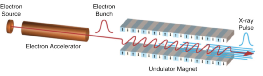
wiggling electrons in an undulator and the radiation they emit over one wiggle period. The gain at this resonant wavelength is due to the phenomenon of microbunching, in which the emitted radiation acts back on the resonant wiggling electrons to increase the orbit length of some and decrease the orbit length of others until they are driven into density modulations at the resonant wavelength. Electrons that wiggle together emit their synchrotron radiation in phase, so that when the bunching is sufficient to overcome the spontaneous synchrotron emission the beam can efficiently convert electron kinetic energy to coherent light.102 The quantum description of this shows that it is in fact the same stimulated emission phenomenon as lasing at optical frequencies. In a typical FEL, the number of photons produced per electron is on the order of 1,000.
High-Intensity Free-Electron Lasers and Scaling of the Fundamental Intensity Limit
The spectral intensity of a conventional laser beam is expressed as the [energy/area-time-bandwidth]. The equivalent figure of merit popularly employed for X-ray sources is the six-dimensional (d3x)(d3k) phase space density measure called the spectral brightness or the spectral brilliance and is expressed in units of [photons/mm2-mr2-second-0.1%bandwidth]. Figure B.53 shows the brightness of some current FELs in these units. When expressed as a phase space volume it becomes clear that there is a maximum possible intensity, which is defined by the product of the diffraction limit and the Fourier transform limit for any laser pulse with a given number of photons.103 For N photons of energy ħω in a diffraction-limited Gaussian beam (FELs typically have this) and with temporal width σt and spectral width σω the fundamental intensity limit is given by:
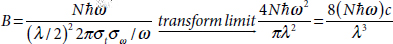
This equation is written to emphasize that Gaussian laser beams have an intensity that scales with wavelength as λ–3 for a constant energy, and as λ–4 for a constant photon number, thus favoring X-ray FELs over optical frequency lasers for high-intensity sources. For the present, however, current sources such as LCLS are not Fourier transform limited at the highest energy levels, and also the technology of X-ray mirrors prevents focusing to waists on the order of the wavelength,104 and so the highest focused intensity for an X-ray FEL is far below this limit. Measured
___________________
102 L.R. Elias et al., 1976, Observation of stimulated emission.
103 A.E. Siegman, 1986, Lasers, Revised edition, University Science Books, Mill Valley, Calif.
104 H. Yumoto, H. Mimura, S. Matsuyama, H. Hara, K. Yamamura, Y. Sano, K. Ueno, et al., 2005, Fabrication of elliptically figured mirror for focusing hard x-rays to size less than 50nm, Rev. Sci. Instrum. 76(6): 63708.
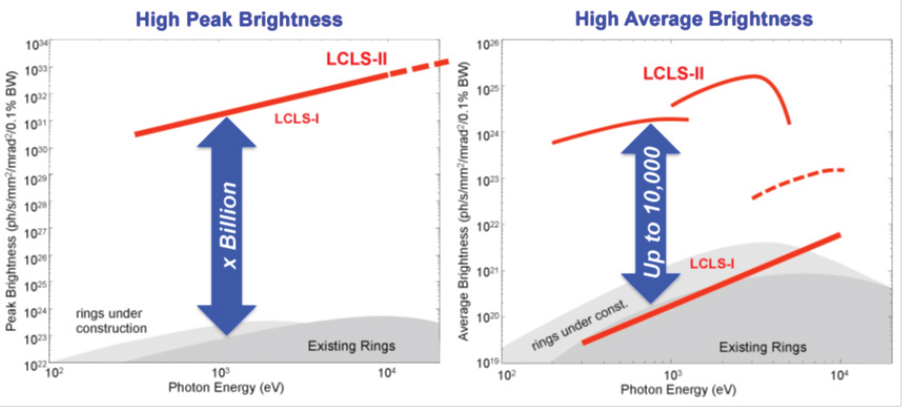
intensities are in the range of 1020 W/cm2, which is below the highest intensity available with optical frequency lasers.105
Average Power
The current average power for these sources is on the order of fractions of a watt (millijoules at 120 Hz), but this will change with the commissioning in the next decade of X-ray FELs based on continuous superconducting linear accelerators. These sources will have average X-ray powers approaching a kilowatt (see Figure B.30 for details).
Transform-limited Pulse Generation
Several methods are under active development to generate transform-limited pulses in X-ray FELs and overcome this major impediment to the highest intensity
___________________
105 H. Mimura, et al., 2014, Generation of 1020 W cm−2 hard x-ray laser pulses.
operation of SASE-based devices.106 There is no intrinsic limit to the gain bandwidth in a free-electron-based gain medium, so in addition transform limited pulses could be extremely short. Attosecond and even sub-attosecond zeptosecond pulse lasers have been proposed.107
In order to generate transform-limited pulses, the electron beam can be manipulated to have only sufficient quality to lase on a single SASE gain spike.108 Self-seeding is another method, where an initial SASE FEL is filtered to produce a transform-limited energy slice, which is subsequently amplified to saturation in a downstream section of the undulator.109 Several methods employ an upstream laser to co-propagate with the electron beam in order to condition its momentum distribution, thereby seeding the microbunching process. These include as examples, harmonic multiplication (HGHG methods),110 the beam echo effect (EEHG),111 and direct injection of harmonics.112
Attosecond and Zeptosecond Pulses
Since the gain bandwidth in an FEL is effectively unlimited there are also many methods proposed and some demonstrated for attosecond pulses or shorter. Most of these are based on using lasers upstream from the undulator to co-propagate
___________________
106 E. Hemsing, G. Stupakov, D. Xiang, and A. Zholents, 2014, Beam by design: Laser manipulation of electrons in modern accelerators, Reviews of Modern Physics 86(3): 897–941.
107 M. Ferrario, J. B. Rosenzweig, L. Serafini, D. J. Dunning, B. W. J. McNeil, and N. R. Thompson, 2014, Proceedings of the workshop ‘Physics and Applications of High Brightness Beams: Towards a Fifth Generation Light Source’ Towards Zeptosecond-Scale Pulses from X-Ray Free-Electron Lasers, Phys. Procedia 52: 62-67.
108 S. Reiche, P. Musumeci, C. Pellegrini, and J. B. Rosenzweig, 2008, Development of ultra-short pulse, single coherent spike for SASE X-Ray FELs, Nucl. Instrum. Methods Phys. Res. Sect. -Accel. Spectrometers Detect. Assoc. Equip 593(1-2): 45-48; J.B. Rosenzweig, D. Alesini, G. Andonian, M. Boscolo, M. Dunning, L. Faillace, M. Ferrario, et al., 2008, Generation of ultra-short, high brightness electron beams for single-spike SASE FEL operation, Nucl. Instrum. Methods Phys. Res. Sect. -Accel. Spectrometers Detect. Assoc. Equip 593 (1–2): 39–44.
109 J. Amann, W. Berg, V. Blank, F.-J. Decker, Y. Ding, P. Emma, Y. Feng, et al., 2012, Demonstration of self-seeding in a hard x-ray free-electron laser, Nat. Photonics 6(10): 693-698; D. Ratner, et al., 2015, Experimental demonstration of a soft x-ray self-seeded free-electron laser, Physical Review Letters 114(5): 054801; A.A. Lutman, F.-J Decker, J. Arthur, M. Chollet, Y. Feng, J. Hastings, Z. Huang, et al., 2014, Demonstration of single-crystal self-seeded two-color x-ray free-electron lasers, Physical Review Letters 113(25): 254801.
110 L. H. Yu, 1991, Generation of intense UV radiation by subharmonically seeded single-pass free-electron lasers, Physical Review A 44(8): 5178–5193.
111 G. Stupakov, 2009, Using the beam-echo effect for generation of short-wavelength radiation, Physical Review Letters 102(7): 074801.
112 T. Popmintchev, M.C. Chen, P. Arpin, M.M. Murnane, and H.C. Kapteyn, 2010, The attosecond nonlinear optics of bright coherent x-ray generation, Nature Photonics 4(12): 822–832.
with and thereby condition the electron bunch in advance.113 Methods to measure sub-femtosecond pulses have also been reported.114 There have even been serious recent attempts to lay the path toward zeptosecond pulses.115
Multi-Terawatt Free-Electron Lasers
The intrinsic efficiency of a SASE-based FEL is the ratio of the photon to electron total pulse energy. At LCLS one 250 pC (1.56 × 10⁹) 15 GeV electrons possess 250 mJ of kinetic energy, which is converted into several mJ of 10 keV laser radiation, so the efficiency is approximately one percent. The limit is due to the loss of the resonance condition when the electrons lose energy and their oscillating orbits shift in the undulator. This could be compensated by changing the period of the undulator to maintain resonance at the same lasing wavelength. Recent studies of undulator tapering predict that extraction efficiencies could be raised to as much as 12 percent, which would then yield a hard X-ray FEL with a power of several terawatts.116
__________________
113 A. A. Zholents and G. Penn, 2005, Obtaining attosecond x-ray pulses using a self-amplified spontaneous emission free electron laser, Physical Review Special Topics - Accelerators and Beams 8(5): 050704; Y. Ding, Z. Huang, D. Ratner, P. Bucksbaum, and H. Merdji, 2009, Generation of attosecond x-ray pulses with a multicycle two-color enhanced self-amplified spontaneous emission scheme, Physical Review Special Topics - Accelerators and Beams 12(6): 060703.
114 N. Hartmann and J.M. Glownia, 2016, X-ray photonics: Attosecond coherent control at FELs, Nature Photonics 10(3): 148–50; N Hartmann, W. Helml, A. Galler, M. Bionta, J. Grünert, S. Molodtsov, K. Ferguson, et al., 2014, Sub-femtosecond precision measurement of relative x-ray arrival time for free-electron lasers, Nature Photonics 8: 706-709.
115 M. Ferrario et al., 2014, Proceedings of the workshop.
116 C. Emma, K. Fang, J. Wu, and C. Pellegrini, 2016, High efficiency, multiterawatt x-ray free electron lasers, Phys. Rev. Accel. Beams 19(2): 20705.


