
3
Current State of Single-Event Effects Hardness Assurance and Infrastructure
Single-event effects (SEEs) hardness assurance—the discipline by which SEE risk is managed—focuses on identifying and bounding risks of SEE vulnerabilities in a device before it is incorporated into flight hardware, because even low probability modes can compromise a mission. This chapter describes the radiation hardness assurance methodology and assesses the existing infrastructure for verifying the ability of existing and emerging microelectronic, optoelectronic, and photonic components to operate properly in the space radiation environment. The committee’s definition of infrastructure includes the following: facilities and related resources necessary to characterize failure modes of electronic components induced by radiation stress; simulation capabilities and related theory and modeling; facilities and related resources available for undertaking those simulations; an inventory of radiation-hardened and/or tested parts, along with the data and models that represent them; workforce available to conduct such simulation and characterization; and the training and research experience programs in place to prepare a workforce for these activities.
RADIATION HARDNESS ASSURANCE APPROACH
The goal of radiation hardness assurance is to identify potential systems failures caused by radiation and to either harden the electronic components to prevent radiation effects or harden the system to prevent system failure as a result of an electronic component upset. SEE hardness assurance has three steps (summarized in Figure 3.1.1 in Box 3.1) as follows:
- Identify the SEE threat. This is done based on knowledge of device technologies and the SEE modes to which those technologies are susceptible in the mission environment. The knowledge of device susceptibilities comes from physics of the device, expert opinion, past testing of similar technologies, etc.
- Evaluate the SEE threat. In this step, data specific to the device are assessed to bound the risk due to SEE. These data may include SEE test data for the device or proxy data that can be used to parameterize a statistical or physical model of likely SEE performance for the device and bound SEE risk to the desired confidence. This step can be iterated if the bound on SEE risk is not acceptable for the application.
- Mitigate the SEE threat. If the bound on the SEE risk remains unacceptable after all reasonable tests and analyses have been applied, the threat can be mitigated, either by replacing the part or using techniques appropriate for the SEE mode(s) of concern and the application.
SINGLE-EVENT EFFECTS HARDNESS ASSURANCE
Testing with heavy ions is usually the most reliable method for bounding risk due to an SEE mode. It also offers the greatest flexibility in tailoring the test to detect the SEE modes of concern, and because heavily ionizing particles are the most effective probes for SEE susceptibilities in semiconductor devices. It is also the most expensive—both in terms of cost and schedule. As such, usually the first attempts to bound SEE risk will involve a search of archival test data to see if the device of interest has been tested previously. In some cases, if data for the part of interest are unavailable, the analyst may attempt to bound the SEE risk by looking at how similar parts fabricated in the same technology performed. (For a discussion of SEE test costs, see Box 3.2.) Table 3.1 summarizes how decisions regarding radiation hardness testing are typically made.
If the a priori analysis described above is insufficient to minimize the SEE risk to an acceptable level, and if the consequences of such an error or failure are sufficiently severe to justify the cost, the part(s) will be scheduled for heavy-ion and, possibly, proton SEE testing.
There are fewer than half a dozen accelerator laboratories that can produce ion beams with sufficient ion species and energies to meet the needs of SEE testing. These facilities are heavily used because they serve the nuclear physics research community, and the entire U.S. governmental SEE testing community (including NASA, the Department of Defense, the Department of Energy, and other government agencies), occasional foreign collaborators, and an increasing number of commercial enterprises eager to take advantage of business opportunities offered by access to space. With the many users competing for time, it is usually necessary to book beam time well in advance, with wait times of 6 to 12 months not uncommon. If long, continuous blocks of beam time are required (as is often the case for a characterization of a complex, state-of-the-art microcircuit or system), then wait times can be even longer.
If the part performs sufficiently well in heavy-ion testing (with no error/failure modes of concern for ions with a linear energy transfer [LET] value of less than ~15 MeVcm2/mg), proton testing or neutron testing may not be needed. If proton beam time is required, it can be booked at one or more of several accelerators used to treat cancer tumors with high-energy protons. Usually, beam time will only be available on weekends when patients are not being treated, and because arrangements with these facilities are still relatively new, the situation with regard to these facilities is still fluid, as will be discussed below.
Whether testing with heavy ions, protons, or neutrons, the test itself is governed/guided by several international standard and guideline documents. These documents make it clear that there is no single SEE test method, but rather many, with each one tailored to detect particular SEE modes, if they are present in the parts being tested. Each of these test methods seeks to achieve all or a subset of the following goals:
- Detect and segregate all SEE modes to which the device under test is susceptible—for simple devices (e.g., bi-stable logic gates), there may be but a single SEE mode. Complex microcircuits may exhibit a range of destructive and nondestructive SEE modes. Seemingly simple operational amplifiers may exhibit a single SEE mode—single-event transients, but these transients may assume a range of wave forms, amplitudes, and durations, which may have different consequences for the system. Finally, some devices may fail via different mechanisms over different ranges of application conditions.
- Accumulate sufficient statistics for each SEE mode such that any variability (e.g., part to part, over application conditions, etc.) can be determined and, ideally, a cross-section can be estimated for each LET value used in the test.
- If cross-sections can be estimated for a sufficiently large number of LET values (e.g., by varying ion species, ion energy, etc.), a cross-section versus LET curve can be constructed. The predominant error on cross-section values is usually Poisson errors on the event count, which diminish as more events are accumulated.
If all of the above goals can be achieved, the device response for each SEE mode and each test condition serves as input for SEE rate-estimation tools to characterize device responses to heavy ions. Unfortunately, some SEE modes are sufficiently complicated that rate estimation is not viable (e.g., for single-event gate rupture [SEGR])
TABLE 3.1 Decision Matrix for Radiation Hardness Assurance
| I am a… | working on… | I need radiation testing because… | My immediate concern is… | If mytest doesn’t occur or has to be delayed, then the impact is on… | Time criticalityof test | |
|---|---|---|---|---|---|---|
| Spaceflight projects | survivability engineer at a large satellite contractor | A high-value US satellite that is months away from preliminary design review | I am not sure whether using some parts will violate mission availability requirements | Uncertainty in SEE susceptibilities in a short list of parts that are lacking information for my application | Project schedule and cost | High |
| systems engineer at a small satellite start-up | A short-lived mission concept that is early in design | I may need to consider radiation effects but they are lower-risk than other problems I are working | My team has no test experience and limited understanding of possible single-event effects | I’m not sure what the impact will be | Low | |
| radiation effects engineer at a satellite contractor | An orbiting satellite | A satellite anomaly happened a month ago. The anomaly response team has narrowed the problem to a single electronics part and I have been tasked with determining whether SEE is the root-cause. |
Whether SEE is the root-cause. I have assembled a test plan for the suspect part and need beam time at a heavy-ion accelerator. |
Delay and risk in return to operations The satellite is safe but near-term and future operation solutions depends on an accurate attribution of the anomaly to unforeseen SEE. Satellites that are in development plan to use the same part and I need to know if they will have a latent SEE susceptibility. |
High | |
| Research | design engineer at a US National Lab | a new detector technology | I need to qualify the new detector for use in space | Whether the new detector will meet mission availability and performance requirements | Mission risk if the new detector has a latent SEE susceptibility | High |
| graduate student | A thesis on radiation effects on a new technology | I have a model of particle energy deposit in a test structure and I want to compare predictions with measurements. | How well my model reproduces the actual energy deposition from heavy-ions | Completion of my student research | Low | |
| space scientist | a new particle mass spectrometer for a heliophysics science mission | Actual particle exposure to a range of heavy elements will ensure my instrument meets its level-1 science requirements | Calibration of my mass spectrometer requires ions at energies similar to what I will measure in space | Project schedule and mission risk | Medium | |
| Industry/Commercial | parts designer at a large chip manufacturer | a new part that I want to market (can be for satellite, aviation, or automotive use) | I need to quantify any SEE susceptibility for the part datasheet | Obtaining sufficient beam time to characterize and benchmark the radiation tolerance of the new part design | My ability to bring my product to market in time | High |
| design engineer for a commercial internet company | a concept for distributed internet service using high-altitude platforms that are not satellites | I need to determine whether some high-performance parts will work in my application | Whether a few parts will upset or fail while operating for long times at high atmospheric altitudes | Mission risk Project schedule and cost | Medium |
or, at least, not usually done (e.g., single-event burnout [SEB]). For these modes, the result is a “safe operating area” (SOA) for application conditions. For instance, for SEB and SEGR, the SOA includes the operating voltages where risk of failure for the test ion is negligible. There may be several SOAs—one for each test ion. In some cases, the question to be answered by the test is merely whether or not the part was susceptible to a given SEE mode at the highest test LET (this is often the way a null result for SEL is presented—e.g., onset LET for SEL > 80 MeVcm2/mg).
SEE test costs are high (see Table 3.2.1 within Box 3.2). Much of the cost is in the manual phases of the tests—preparation, test development, and analysis and reporting. Consequently, it has been difficult to reduce overall cost significantly, even by scaling back the scope of the test and accepting increased risk. Figure 3.2.1 illustrates a breakdown of SEE test costs by type for testing of a DDR SDRAM (double-data rate synchronous dynamic random-access memory) device by an experienced NASA radiation testing group. As can be seen, test costs are front loaded, with nearly 70 percent of costs going to highly skilled labor and more than 50 percent of the costs being needed for test development. Less than 30 percent of the cost is incurred in the execution of the test, and beam costs only account for about half of this (~15 percent of the total test cost), assuming testing is done at Texas A&M University (TAMU). If instead the testing were done at the NASA Space Radiation Laboratory, beam costs would account for ~41 percent of the total test cost. A less established testing group with less experience could wind up with an even higher proportion of up-front costs for procurement of test hardware and test development.
Finding: The complicated packaging and high level of integration of many COTS (commercial-off-the-shelf) parts has made them increasingly difficult to test at conventional heavy-ion accelerators. In many cases, the only options for testing such parts are the following:
- Costly and risky modification and/or repackaging of the part to ensure ion beams can reach sensitive volumes in the device.
- Testing at an expensive and difficult-to-access ultra-high-energy ion accelerator to ensure that ions have the range to reach device sensitive volumes.
- Testing with protons only and accepting the residual risk of heavy-ion-induced destructive SEE or other hidden SEE modes not revealed by such a test.
When the rate and consequences for the SEE mode are quantified, the consequences must be propagated to the circuit, subsystem, and system levels so that the impact on mission requirements can be assessed. When the device under test is sufficiently complicated (e.g., microprocessors, Field Programmable Gate Arrays [FPGA]), then the consequences, even at the chip level, may not be obvious from the test results. Thus reliability models are required that span many levels of integration.
Even when the mission launches, the radiation analyst’s work continues, using on-orbit performance of mission hardware to validate the methods used in qualifying that hardware. Thus the hardness assurance loop closes for the next mission.
Box 3.3 provides an overview of the infrastructure to support a successful SEE risk evaluation and reduction process.
TEST METHODS FOR DIFFERENT SINGLE-EVENT EFFECT MODES
SEE testing is governed by internationally accepted standards and guidelines that incorporate the body of knowledge for destructive and nondestructive SEE modes. (See Table 3.2.)
These test methods are sufficiently flexible that if a new SEE mode is discovered in testing, it can be characterized to determine how it depends on ion characteristics, application conditions, and other variables. At present, these test methods are geared toward either constructing a SEE cross-section versus LET curve suitable for rate estimation using CRÈME-96 (see below in the section on modeling and simulation) or similar methods, or if rate estimation is not feasible (e.g., SEB and SEGR), identifying safe operating conditions for avoiding these effects. At present, test techniques are not optimized for more complicated physics-based Monte Carlo SEE rate-estimation methods.
TABLE 3.2 Governing Single-Event Effects (SEEs) Test Documents
| Type of Testing/Environment | Available Standards, Guidelines, and Methods |
|---|---|
| Proton SEE Testing | JEDEC JESD234: Test Standard for the Measurement of Proton Radiation Single-Event Effects in Electronic Devices (2013) ESCC 25100: Single-Event Effects Test Method and Guidelines (2014) |
| SEE Testing for Terrestrial Effects | JEDEC JESD89: Measurement and Reporting of Alpha Particle and Terrestrial Cosmic Ray–Induced Soft Errors in Semiconductor Devices |
| Heavy-Ion SEE Testing | ASTM F1192-11: Standard Guide for the Measurement of Single-Event Phenomena (SEP) Induced by Heavy-Ion Irradiation of Semiconductor Devices JEDEC JESD57: Test Procedures for the Measurement of Single-Event Effects in Semiconductor Devices from Heavy-Ion Irradiation (under revision) ESCC 25100: Single-Event Effects Test Method and Guidelines (2014) |
| Heavy-Ion Test for SEB/SEGR | MIL-STD-750, Method 1080: Single-Event Burnout and Single-Event Gate Rupture |
ASSESSING FACILITIES
As discussed above, SEE testing is done with both protons and heavy ions. SEE testers are secondary users at all of the accelerators where they test. The heavy-ion accelerators were built to serve the nuclear physics community at the facilities where they reside (universities or national laboratories). The proton accelerators used for SEE testing are at medical facilities dedicated to treating cancer and other diseases with radiation. This report considers each proton and heavy-ion accelerator separately.
Proton Accelerators
Up until recently, there were five facilities in the country with proton accelerators (see Table 3.3). Up until a decade ago, the NASA Space Radiation Laboratory (NSRL) was used for high-energy proton testing. However, the high costs, temporal structure of the beam, and high demand for the facility for other testing have meant that it is rarely used for proton testing at present. With the closure of the proton accelerator at the Indiana University Cyclotron Facility (IUCF) in 2014, the radiation community lost its major workhorse for high-energy proton testing. While there are several facilities that had experience with proton SEE testing, IUCF provided more hours for electronics testing with more flexibility of access. The remaining facilities are active cancer treatment centers, and as such can only do SEE testing on weekends, making it difficult to meet the demand for proton beam time.
Heavy-ion testing is critical to all of these efforts to harden electronics to the space radiation environment, and loss of any of the current facilities could pose significant risks for future U.S. space missions.
To make up for the loss of proton beam hours and to ensure quality across the testing community, a consortium consisting of the NASA Electronic Parts and Packaging (NEPP) Program, the U.S. Air Force, and other interested parties has been evaluating and consulting with medical proton accelerator facilities. To date, 26 proton accelerators have been evaluated in the continental United States (including three listed in Table 3.3), and 11 proton treatment centers under construction have been identified. Some of these facilities will provide beam time for electronics testing on weekends when they are not treating cancer patients. However, it is difficult to anticipate demand patterns for proton beam therapy. As such, the situation with regard to participation, beam characteristics, cost, and scheduling remains fluid. At present, although wait times have increased, most SEE testers have been able to find beam time when they need it. This would not be the case if a critical accelerator (e.g., TAMU, LBNL, or Francis Burr) were to close.
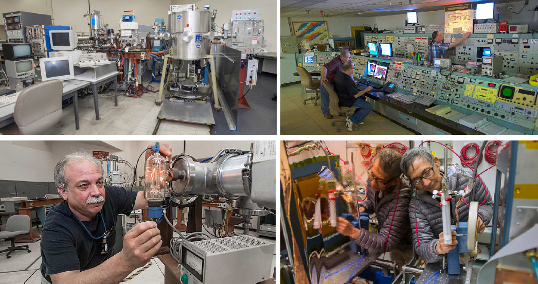
The situation with respect to medium- and low-energy proton testing has also been unsettled. Medium-energy protons (50–70 MeV) are occasionally used for SEE testing, but more often are used for displacement damage studies on detectors, optoelectronics, and other potentially vulnerable devices. The Crocker Nuclear Laboratory at the University of California, Davis (UC Davis) has been the workhorse facility for the medium-energy range (see Figure 3.1). However, costs for beam time there have fluctuated, rising in 2015 and falling in 2017. It also has had trouble finding enough qualified accelerator operators to meet needs.
TABLE 3.3 High-Energy Proton Accelerators with Single-Event Effect (SEE) Test Experience Prior to 2014
| Proton Facility (Location) | Comments/Status |
|---|---|
| Indiana University Cyclotron Facility | Closed in 2014. |
| Massachusetts General Hospital Francis H. Burr Proton Therapy Center (Boston) | Highly experienced competent staff, motivated to facilitate SEE testing, wait time >12 months. |
| TRIUMF (Vancouver, BC, Canada) | Lots of SEE test experience and beam energies up 480 MeV. Limited beam runs per year. Location in Canada can pose challenges for transport of test equipment. |
| Loma Linda Univ. Medical Ctr. (Loma Linda, California) | Significant experience with SEE testing. Limited availability. |
| Proton Therapy Ctr. (San Diego, California) | Significant experience with SEE testing. Limited availability. Declared bankruptcy in 2017. |
LBNL and TAMU can also provide proton beams in this energy range. Low-energy proton beams for investigating SEE due to direct proton ionization in deep submicron CMOS processes can be found at a variety of facilities, including UC Davis, NASA Goddard Space Flight Center, and Vanderbilt University. Relatively little low-energy proton testing is currently being done, except for research purposes, so beam time is usually available.
Heavy-Ion Accelerators
Heavy-ion testing allows the ion characteristics (species, energy, angle of incidence, etc.) and application conditions for each test run to be selected. For this reason, and because they are much more ionizing than protons, heavy ions are the preferred probe for revealing SEE susceptibility in devices under test. The following several characteristics make a good heavy-ion test facility:
- It must be able to deliver ions into device-sensitive volumes such that they deposit a reproducible and predictable amount of charge. The lower the ion energy, the fewer parts there are that can be tested without significant, risky modifications to the part.
- It must be able to change ion species, energy, LET, and angle of incidence relative to the device.
- It must provide accurate counts of particles incident on the device.
- It must accomplish all of the above in a timely fashion and as economically as possible.
- It must provide ions with sufficient energy so that testing in air rather than in a vacuum is possible, because this makes the test hardware more accessible and reduces thermal challenges.
- A cyclotron is more desirable than a synchrotron, where ions arrive in packets with a cyclic structure. For the many microelectronic parts that operate in synchrony with an internal or external clock, it is highly desirable that ions arrive at the die randomly in time.
At the other end of the energy spectrum, LANL has proposed the development of a proton accelerator capable of providing protons with energies from 200 to 800 MeV. This facility could be useful for trying to elucidate destructive SEE susceptibilities in some microelectronics. However, because the accelerator would be a synchrotron, caution and analysis may be required when testing complex, synchronous devices.
All of the facilities discussed below and itemized in Table 3.3 offer adequate control of beam characteristics (itemization 2 above) and dosimetry (itemization 3 above). However, they vary in terms of their beam penetration, availability, and cost. By far, the overwhelming majority (>90 percent) of heavy-ion beam-hours are provided by the two main accelerators—the K500 accelerator at the TAMU Cyclotron Facility (providing ~3,100 hours/year) and the 88-inch cyclotron at LBNL (providing 2,000–2,500 hours in most years). (See Figures 3.2 and 3.3.) TAMU has been operating near capacity (even above capacity in 2016) for several years. LBNL operations are limited by its funding structure and sources. In 2016, the loss of guaranteed funding from a sponsor resulted in 30 percent less beam time being available compared to the previous year.
Table 3.4 lists the heavy-ion accelerators currently or recently in use in the United States, along with some of their characteristics. More details by facility are given in the following sections.
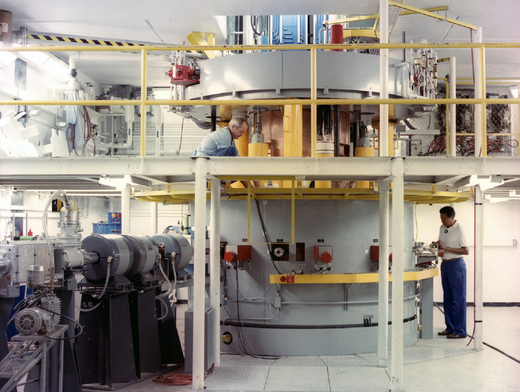
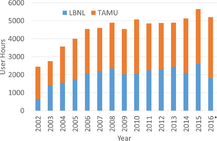
TABLE 3.4 U.S. Heavy-Ion Accelerators Currently/Recently in Use
| Facility | Energy Range MeV/nucleon | Test Environment | Beam Cost | Beam Hours | Comment/Challenges/Advantages |
|---|---|---|---|---|---|
| TAMU | 15–40 | Air | ~$1,000 | ~3,000 | Near capacity with increasing wait times; broad range of ion test energies, species |
| LBNL | 4.5–30 | Vacuum | ~$2,300 | 2,000–2,500 | Availability has fluctuated due to financial challenges; fast beam changes |
| NSRL | 50–1500 | Air | ~$6,000 | 100–200 | Could provide more SEE test hours/cost and beam structure/broad range of ion test energies, species; fast beam changes |
| SEUTF | ~1.7–8 | Vacuum | ~$1,000 | ~100 | Low-beam energy not suitable for all tests and technologies |
| NSCL | 72–143 | Air | ~$5,500 | 0 | Not available—future site of Facility for Rare Isotope Beams |
NOTE: LBNL, Lawrence Berkeley National Laboratory; NSCL, National Superconducting Cyclotron Laboratory; NSRL, NASA Space Radiation Laboratory; SEUTF, Single-Event Upset Test Facility; TAMU, Texas A&M University.
TEXAS A&M UNIVERSITY CYCLOTRON FACILITY
TAMU is the workhorse facility for heavy-ion SEE testing, having provided 3,100 hours during 2016. The facility provides a range of ions with atomic numbers from 1 to 79 and LET from 0.1 to 93 MeVcm2/mg and energy tunes of 15, 25, and 40 MeV/nucleon. Testing can be done either in a vacuum or in air. Costs are comparable to those paid at most proton or heavy-ion facilities. TAMU seeks to provide roughly 3,100 hours of beam time for SEE testing (and roughly an equal amount for nuclear science), and in the last several years has come close to this goal. The higher energies at TAMU make it easier to test many devices that are highly integrated or in packages that are difficult to test. However, some parts require still higher test energies.
Testing at TAMU poses some challenges. Beam time is in high demand at this facility, so it can sometimes be challenging to get time there. Also, although the 25- and 40-Mev/nucleon ions have fairly good penetrating
power, it may not be sufficient to penetrate parts in challenging packages or highly integrated parts with multiple stacked die. For such parts, risky, expensive, and complex alteration of the parts may be required to ensure that the beam reaches the sensitive volume.
Although the accelerator is well past its design life, it continues to operate reliably, albeit with occasional breakdowns that may take weeks for repair and full recovery of operations. The facility is also trying to improve access by offering beam time on a smaller (K150) cyclotron, although this machine has yet to add significant hours.
LAWRENCE BERKELEY NATIONAL LABORATORY
The Berkeley Accelerator Space Effects (BASE) Facility was the site of the first SEE test in 1979—just 7 years after the discovery of SEEs. In recent years, the facility has provided up to ~2,500 user hours for electronics testing, providing ion beams from protons to bismuth (LET >99 MeVcm2/mg) and beam tunes of 4.5, 10, and 16 MeV/nucleon. In July 2017, LBNL introduced a 21-MeV/nucleon beam tune for a few light ions (and includes Xe), significantly increasing ion range and simplifying the task of testing some difficult parts in challenging packages.
BASE offers the fastest beam changes of any widely used accelerator because it provides a “cocktail” of ions in which several ion species are accelerated at the same time, and the desired species is then selected for delivery to the experimenter. The cocktail makes switching ion species quick, as long as one stays with the same energy tune. This decreases the time required to construct a cross section versus LET curve and can make testing more economical.
The main challenge at BASE is the way the facility is funded. In recent years, beam time has been paid for in advance by the U.S. Air Force and other government agencies and then dispersed to projects needing the test facility. In 2016, one government agency withdrew from this form of strategic funding. Without this guarantee of funding, BASE reduced its operations, with the result that it could only provide ~1,800 hours of beam time, a reduction of about 700 hours of beam time from previous years. This precarious funding situation persists. Costs are driven by labor and by the limited number of “planned hours” scheduled, which has made beam time at BASE more expensive than TAMU. In addition, the 88-inch cyclotron (equivalent to the K150 machine at TAMU) is even older than the TAMU machine, raising concerns about its future reliability. Were the BASE facility to close due to either funding or reliability concerns, it is unlikely TAMU and the other facilities could provide sufficient beam time to meet community testing needs. According to BASE management, the facility could provide more beam time if the prospects for additional funding were longer term, because this is primarily an operational issue.
NASA SPACE RADIATION LABORATORY
NSRL was developed at Brookhaven National Laboratory with the intention of studying the effects of high atomic number (Z), high-energy ions (so-called HZE radiation) on biological samples. To do this, it had to have ions that were representative of the galactic cosmic ray environment in terms of both energy and ion species. This makes the facility an excellent candidate for investigating the effects on electronics caused by these same ions (see Figure 3.4).
Ions from hydrogen to gold can be provided with energies from a few hundred MeV to more than 1 GeV per nucleon. These ions can penetrate up to several centimeters of overburden due to the package and die and deposit energy in the sensitive volume of most semiconductor components. They make it possible to carry out realistic studies of multi-bit upsets and other phenomena that would be impossible at lower-energy facilities. The facility has also become a lot more user friendly. For instance, it can now change ion species in a matter of minutes, significantly lowering the cost of construction of a SEE cross-section versus LET curve.
Cost, however, remains one of the biggest obstacles to greater use of this facility, with beam time costing ~$6,000/hour, ~6 times (or more) the cost of lower-energy facilities. Accessibility is also more difficult, requiring an application for a Strategic Partnership Project Agreement and funding for beam time more than 30 days in advance of the test. Also, the accelerator at NSRL is a synchrotron, so the ions arrive in bunches at a particular frequency. This can be problematic for testing some devices that operate synchronously. These factors have limited use of the facility to about 100 hours per year for electronics testing.
Despite these difficulties, NSRL’s high-energy ion beams and the increasingly user-friendly facilities suggest this facility could see greater use in the future—particularly as users develop strategies for making more efficient use of beam time to offset higher beam costs.
BROOKHAVEN SEU TEST FACILITY
The SEU test facility at Brookhaven National Laboratory provides low-energy heavy-ion beams from a tandem Van de Graaff accelerator. The facility saw greater use in the 1990s than it does today. However, because the ions it supplies have ranges in Si of only 20 to 40 microns, use of the facility has decreased over the past two decades. The short ranges of the particles make testing for destructive SEE problematic, and they necessitate testing in a vacuum, increasing the chance of thermal issues with the test parts and board. In 2016, the community used only about 80 hours of beam time at this facility. Nevertheless, the facility does provide a range of ions (from hydrogen to gold) and is suitable for many studies of nondestructive SEE. Beam costs are similar to those at TAMU and LBNL.
NATIONAL SUPERCONDUCTING CYCLOTRON LABORATORY AT MICHIGAN STATE UNIVERSITY
The National Superconducting Cyclotron Laboratory (NSCL) is another high-energy cyclotron where heavy-ion SEE testing has been conducted in the past. The facility is no longer active, because the laboratory will be the home of the Facility for Rare Ion Beams (FRIB). However, when it operated, it was capable of providing ions up to uranium with energies on the order of 100 MeV per nucleon. Beam time was expensive (~$5,000), and beam changes were time-consuming and costly.
OTHER SINGLE-EVENT EFFECT TEST FACILITIES AND TECHNIQUES
One of the most useful techniques for revealing SEE susceptibilities in electronics has been the use of a pulsed laser. In this technique, a visible or infrared laser is focused on a feature of interest in the device under test, the laser pulse is focused at the desired depth, and the response of the device is observed. Because the technique focuses the beam spot down to about 1 micron diameter, it is useful not just for identifying SEE susceptibilities in a device but also for identifying the particular feature responsible for the effect. Unfortunately, it has proven difficult to develop a general method for equating the energy delivered by the laser pulse to a particular ion LET. This, coupled with the difficulty of fully automating the technique and the sheer number of ion pulses required to cover a chip 1 μm2 at a time, has meant that this technique is more of a complement to rather than a replacement of heavy-ion testing. Moreover, if the die is covered with a significant percentage of metal, or if there are irregularities on the surface of the part, some features may not be reachable with a laser. At the very least, significant preparation or alteration of the part may be required for this technique to be useful.
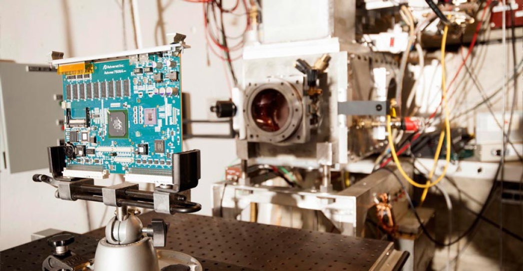
More recently, investigators have begun using synchrotron X-ray pulses from the Advanced Light Source at Argonne National Laboratory to investigate SEE susceptibilities in some simple devices. These techniques may surmount the limited resolution of laser testing as well as penetrate packaging and metallization over the sensitive volume. Although this technique is still an active area of research, it bears watching for the future (see Figure 3.5).
SUMMARY SINGLE-EVENT EFFECT TEST FACILITIES AND TECHNIQUES
Although SEE test facilities have been able to meet demand for most users to date, this infrastructure is showing signs of strain. The closure of the Indiana University Cyclotron Facility, the bankruptcy at Scripps Proton Therapy Center, and the ongoing financial turmoil at LBNL are indications of this strain. The loss of roughly 30 percent of LBNL’s beam hours in 2016 significantly increased demand at TAMU and resulted in increased wait times for testers. In addition, many of the accelerators in use for SEE testing are significantly older than their design life, and a failure of critical systems is becoming more likely—especially if the financial health of the facilities does not permit increasing maintenance and replacement of vulnerable components prior to failure.
Finding: The proton and heavy-ion SEE testing infrastructure is showing increasing signs of fragility and strain. Although the community has been able to find beam time at medical proton test facilities, the list of facilities willing to participate in this effort has been in a state of continual flux.
Single-Event Effect Test Hardware
In order to glean useful data from an SEE test, the experimenter must monitor the part’s behavior as it is irradiated with ions. This requires test hardware—and the more advanced the part, the more advanced the test hardware must be. If the goal of the test is to measure the transients on the output of an operational amplifier, an oscilloscope may be sufficient. On the other hand, understanding the SEE response of a state-of-the-art field-programmable gate array (FPGA) will likely require a custom tester built with state-of-the-art parts. If the test part is operated at high speed, special cabling may be required as well. Moreover, the rapid pace of electronics development often means that what was a state-of-the-art tester a few years ago will be obsolete for the next generation of parts.
Test hardware development is costly and involves the concerted efforts of highly skilled engineers and technicians. The skilled staffing costs needed for part procurement, preparations, and test procedure and harness development can easily account for half of the cost of test development, before the part sees a single ion. And the fast pace of electronics development means that it will be a recurring cost as current electronic parts become obsolete and the next generation of advanced parts and evolving technologies require new tests and analysis.
Availability of Radiation-Hardened Parts
COTS parts often provide a critical performance advantage for satellite missions. In some cases, they provide the critical boost to performance required to meet mission requirements. Often a cost for performance trade is done, and in spite of the COTS part being used in a critical system, the COTS part is the only way to meet cost and schedule demands. In such a case, radiation testing may be critical for selecting the best COTS option as well as the best strategy for quantifying and minimizing the risk of using that part. Unfortunately, because COTS parts—by their very nature—were never intended to operate in a space radiation environment, they often wind up dominating the design and qualification efforts for the hardware in which they are used. Some missions may also use COTS components due to their lower procurement costs, or the fact that unlike many radiation-hardened parts, they can be procured immediately with little delivery delay. However, if the parts are used in a critical application, the cost and schedule hits due to qualification and validation often make these seeming advantages vanish.
This weakness is a serious concern for builders of small satellites (SmallSats), CubeSats, and other risk-tolerant platforms, because these missions are often driven to use COTS parts due to stringent demands on schedule, board space, performance, and cost. In addition, small companies often lack access to experts who could help them adapt traditional tests to meet their specific needs. In the absence of a strong body of knowledge about these parts, the only way to ensure their reliable operation is by SEE testing, and SEE testing likely exceeds the budgets of these missions.
For this reason, it is critical that spacecraft have access to data on a broad variety of radiation-hardened and radiation-tolerant parts—not only to ensure that critical elements in the hardware operate reliably, but also to keep the designers and radiation analysts from becoming overwhelmed by COTS-related challenges.
Suppliers of radiation-hardened parts face the difficult challenge of justifying to management and shareholders that they provide a useful return even though their market is miniscule compared to commercial electronics. They face an equally skeptical audience in their customers as they try to justify the high prices of their products compared to COTS alternatives—some of which may exhibit radiation performance comparable to the radiation-hardened parts but have not been tested or analyzed.
At the present time, the marketplace for radiation-hardened semiconductor devices appears to be functioning. New products are reaching the market and capabilities are increasing significantly—albeit more slowly than in the commercial market. The chief source of attrition of vendors of these parts appears to be consolidation, as a larger supplier buys up smaller competitors. For example, in 2011, Texas Instruments acquired National Semiconductor, and in 2014, Infineon (a European company) bought International Rectifier—the main manufacturer of radiation-hardened power MOSFETs, critical components in power systems. In 2016, Analog Devices bought Linear Technologies, and Renesas acquired Intersil. In all of these instances, the acquiring company also had a branch supplying radiation-hardened parts prior to the acquisition. However, in all cases, the acquiring company derived much less of its business from the radiation-hardened branch than did the original company. To date, little has changed as a result of these mergers. Radiation-hardened products continue to be produced at more or less the same rate. However, it will be interesting to see if these trends persist across a few business cycles. As the current study was being finalized, Honeywell announced that it would be closing their foundry in Plymouth, Minnesota. Although other vendors offer parts capable of fulfilling the functions of standard parts from this foundry, this development could represent a significant concern for programs that are reluctant to send their intellectual property to an offshore foundry.
SEE data often remain valid as long as the part is available. However, for some commercial users, current radiation-hardened parts are not able to meet the demands of the payload community for price versus performance. In many cases, they cannot meet performance requirements at all (e.g., high-speed Ethernet bus hardware). Making the same performance available in space that users have come to expect terrestrially would go a long way toward making space more enticing to the commercial market.
DATA
Single-Event Effect Testing Databases
Another resource that is critical for preventing radiation test and qualification costs from escalating out of control is the archive of historical SEE test data in various databases and in the journals and conference proceedings for radiation effects. Table 3.5 summarizes all available databases. Sometimes one can also ask satellite vendors and managers of other programs for data deemed proprietary.
TABLE 3.5 Single-Event Effect Testing Databases
| Database | Website | Comments |
|---|---|---|
| GSFC Radiation Data Base (NASA Godard Space Flight Center) | https://radhome.gsfc.nasa.gov/radhome/raddatabase/raddatabase.html | At present, the only U.S. database open to the public without registration |
| ESA Radiation Reports (European Space Components Information Exchange System; European Space Agency) | https://escies.org/labreport/radiationList | |
| JPL RAD Archive (Jet Propulsion Laboratory) | https://radcentral.jpl.nasa.gov | Requires registration |
| IEEE Nuclear and Space Radiation Effects Conference (NSREC); Radiation and its Effects on Components and Systems (RADECS) Conference; IEEE Radiation Effects Data Workshop | http://ieeexplore.ieee.org/Xplore/home.jsp | Publishes yearly radiation effects data workshop proceedings; proceedings can be accessed via the IEEE literature search tool |
Although these resources include test reports on the SEE response of hundreds of semiconductor devices, use of these data poses challenges, especially for small missions that use large numbers of COTS components.
First, most testing is done by conventional builders of satellites and spacecraft. Most of these builders use COTS parts only in small numbers to capitalize on the performance advantage they confer. As such, there are relatively few COTS parts featured in most of these databases. Because the builders are using COTS for their performance advantages, they are more likely to deem the test results sensitive and proprietary. Moreover, the short product life cycle for such parts means that most test reports are out of date less than a year after they are published. Thus, an analyst seeking guidance for a COTS part is unlikely to find it from the existing literature.
A second challenge has also been exacerbated by increased use of COTS. Because many of these parts are complicated, it is difficult if not impractical to carry out a full characterization of the part’s radiation response for all operating modes and all configurations of the parts in space. Most test reports are to some extent specific to the application the tester is addressing. Radiation response of complex parts depends on a variety of factors, including application voltages, operating mode, frequency, and so on. Although it may be possible to infer something about a part’s radiation response for conditions other than the test conditions, this will depend on the complexity of the part and on the analyst’s experience and familiarity with the part. Like many tasks in radiation hardness assurance, interpreting data benefits from an experienced and well-informed analyst.
To date, these challenges have been manageable because the radiation-hardness assurance community is relatively small. A significant proportion of the community attends one or more of the yearly conferences where data and new results are disseminated, and there is a single journal of record (IEEE Transactions on Nuclear Science) in which the overwhelming majority of new results are published. An additional journal, IEEE Transactions on Device and Materials Reliability, can also be useful for some purposes. This closeness of the community makes it straightforward to place data in context and avoid extrapolating results to applications where they would not apply. For new engineers entering the field as the commercial space industry grows, sources of data may not be known and context may be more difficult to obtain. This could increase demand for a centralized database for results from satellite builders. In the United States, much of the data available to builders of both conventional satellites and SmallSats, and much of the expertise for interpreting it, resides at NASA.
On-Orbit Data and Validation of Methodologies Used for Single-Event Effect Hardness Assurance
Given growing capabilities in space, especially commercial spacecraft that can support on-orbit technology development, it is feasible that more radiation-hardness assurance testing can occur on-orbit (as distinct from simulating the space environment terrestrially). However, anyone who has served on an anomaly review board can testify to the difficulty of understanding spacecraft operations based on the limited telemetry available. A radiation analyst attempting to validate methodologies and assumptions from on-orbit performance of spacecraft faces a similar task. Usually, if the spacecraft is operating nominally, subject-matter experts hear nothing. If anomalies are observed, the expert may be called on to explain the cause or more likely to develop work-around strategies. Once the behavior of the spacecraft is understood, the work-around strategies and the recovery operations become routine, and little further information is likely to be forthcoming. In some cases, spacecraft operators will make data on performance of critical systems available, and the testing and analysis of particular critical devices can be analyzed. Some of the most detailed comparisons of predicted and observed SEE rates were made to validate SEE rate-estimation models (Petersen, 1997, 2008; Ladbury, 2009; Schaefer, 2009). Such on-orbit data are invaluable for validating SEE risk-management tools. Unfortunately, it often depends on informal relationships between individuals on the radiation team and in the operations team of a satellite.
Models
Radiation Environment Models
As mentioned at the beginning of Chapter 2, ionizing particles of concern for causing SEE derive from three sources—galactic cosmic rays (GCRs), solar particle events, and trapped protons. For nearly 20 years, the
de facto standard model for GCRs has been the CRÈME-96 model used in the CRÈME-96 SEE rate-estimation tool. The main shortcoming of this model is that it has limited options for capturing the variability of the GCR environment—having only two options: solar maximum and solar minimum. While this limits the model’s ability to capture the variation of GCR fluxes from one solar cycle to the next, the effects on SEE rates are usually not significant compared to other sources of error in SEE rate estimations.
Potentially, more flexibility exists for capturing the variability of the solar particle and trapped proton environments since the introduction of probabilistic models of these environments. The Emission of Solar Protons (ESP) and Prediction of Solar Particle Yields for Characterizing Integrated Circuits (PSYCHIC) models allow solar event proton and heavy-ion (respectively) levels to be selected for a desired confidence level. Similarly, the AP9 model allows trapped proton levels to be evaluated for any orbit at any desired confidence level. In principle, the proton and heavy-ion fluxes versus energy can be imported into rate-estimation tools and the rate evaluated for the mission environment at the desired confidence level.
In practice, few take full advantage of these capabilities. AP9 is fairly new and is still undergoing revisions (albeit minor ones). CRÈME-96’s built-in models still include AP8 (for both solar maximum and minimum) and a “worst-case” solar particle event model with peak, worst-day, and worst-week proton and ion flux versus LET distributions. These models are adequate for most SEE rate estimation analyses.
The tools and models described here have proven sufficiently accurate that they do not significantly increase errors on SEE rate estimations (Petersen, 2008).
SEE Rate-Estimation Models
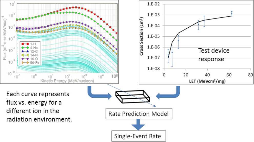
Bounding SEE risk requires knowing the probability that a given SEE mode will manifest in the mission. The rectangular parallelepiped (RPP) method of SEE rate estimation has been the standard method for more than 25 years. The method models SEE as occurring when an ionizing particle with constant LET traverses a single sensitive volume in the form of a thin rectangular slab surrounded by inert silicon. If the dimensions of this slab are known, the distribution of chord lengths through it can be calculated exactly. In addition, the method assumes the LET of the ion is constant as it traverses the sensitive volume, that nuclear reactions are negligible, and that the charge responsible for the SEE is generated by energy loss of the ion. The rate-estimation process is illustrated in Figure 3.6.
CRÈME-96 is an example of an integral RPP SEE rate-estimation model. Its emergence as the primary rate-estimation tool is in part attributable to the fact that it includes all the models and routines needed to estimate relevant SEE rates; models of GCR, solar particle, and trapped proton fluxes; and routines for transporting the space environments through the geomagnetic field and through spacecraft materials, and plotting routines. Another popular feature is that it is available free to the user. The test methods documented in Table I are optimized to provide precisely the sort of cross-section versus LET curve required by CRÈME-96 and other similar methods.
If the assumptions of constant LET, RPP sensitive volume, no nuclear reactions, and so on are violated, the user will have to use a more complicated tool for rate estimation. One such tool is the Monte Carlo Radiative Energy Deposition (MRED) package (developed by the Institute for Space and Defense Electronics at Vanderbilt University), which is an example of such a physics-based model. For this SEE rate estimation, one constructs a model of the device structures and propagates the desired ion flux environment through this model, counting the events that deposit sufficient energy in the sensitive volume to cause an SEE. The MRED package uses realistic physics models for transport and energy loss of the ion, charge transport, nuclear interactions, and material properties of the device. This allows rates to be estimated for parts where CRÈME-96 would fail. The challenge for Monte Carlo methods is in constructing the device model. It is unlikely that one would be able to glean sufficient detail solely from broad-beam heavy-ion testing to construct such a model. To date, this method has been used most successfully when the radiation analyst works closely with the vendor of the part to develop such a model.1 One can then investigate the characteristics and susceptibilities of the model and validate the results with a heavy-ion test.
___________________
1 Admittedly, sometimes vendors are unwilling or unable to work with spacecraft contractors due to the proprietary nature of the chips being modeled.
A somewhat scaled down and more user-friendly Monte Carlo SEE rate-estimation method was also developed at Vanderbilt—CRÈME-MC. This package is available at the same site where the CRÈME-96 model is hosted. It allows the user to construct more complicated models of the sensitive volume than can be analyzed by CRÈME-96. CRÈME-MC and MRED are expected to become more important as microelectronic technology features continue to shrink and the assumptions of the CRÈME-96 become increasingly inaccurate.
Despite the central role of CRÈME-96 and CRÈME-MC, the infrastructure that hosts this critical community resource has also exhibited fragility. Especially since Vanderbilt is still hosting the rate-estimation packages only because of emergency funding provided by NASAs NEPP program. Without this funding, these critical elements of the radiation-hardness assurance infrastructure might have been jeopardized. It is hoped that the packages will find a new home in 2018. Regardless of the method, rate estimation cannot rely on modeling alone. SEE test data are required to constrain it. Even if using a full-blown Monte Carlo rate-estimation tool and a computer-aided design (CAD) model of the device structure, the results must still be validated to ensure the CAD model is truly representative of the microelectronic device.
SINGLE-EVENT EFFECT PROPAGATION FROM THE DEVICE TO THE SYSTEM LEVEL
SEEs are a prime example of an event occurring on a very small (nanometers) scale having consequences on a much larger scale (e.g., a satellite or larger). Unfortunately, propagation of errors from the device level to the system level remains a gap in capability for the field that can lead to significant over-estimation of failure rates. In the past, SEE analyses simply assumed that every SEE that occurred manifested with worst-case consequences
at the system level. Likewise, many upset bits may have no observable effect on a complex system because they may be manifested in scratch memory, be overwritten immediately, not occur in a sensitive area, and so on. As a result, such an analysis yields unreasonably pessimistic and unrealistic results. At present, developing tools for realistic error propagation in complex systems remains a gap, but it is a gap that designers and researchers are actively trying to fill.
Fault injection analyses in microprocessors provide an intuitive method of following error propagation. In such studies, a particular bit is assumed to flip at a particular stage of a code’s progress. That error is programmed into the device, and the code executes from that point. Results depend heavily on the code being executed. However, in some cases, more than 90 percent of the errors had no effect on the functioning of the processor. Unfortunately, again, the complexity of microelectronic devices precludes detailed fault injection analyses spanning the phase space of even a single complex microchip, let alone a system.
Instead of brute-force methods such as fault injection, many organizations have begun to use Model-Based Systems Engineering and Model-Based Mission Assurance as a way of identifying critical components and failure modes in a system (Evans, 2016). These techniques are still under development, and the level of fidelity required for the full system remains to be determined.
PEOPLE—WORKFORCE, EDUCATION, AND TRAINING
As indicated in the preceding discussion, much of the success of hardness assurance depends on a well-trained, knowledgeable, and experienced workforce. Although individual radiation experts have particular specialties, success in radiation hardness assurance requires understanding of the space environment and the available models thereof; semiconductor devices and technologies and their radiation susceptibilities; test development, preparation, and execution; data analysis; and spacecraft design.
BODY OF KNOWLEDGE OF SINGLE-EVENT EFFECT MODES FOR AVAILABLE SEMICONDUCTOR TECHNOLOGIES
Keeping abreast of the current state of the art with respect to SEE mechanisms and vulnerabilities is challenging for several reasons. First, as indicated in the introduction to this section, SEEs manifest in a variety of modes with a range of consequences. Second, the basic subject matter of SEE hardness assurance is microelectronics, which evolves—literally—at an exponential pace. Fortunately, the physics underlying basic SEE mechanisms is just the deposition of energy in materials by ionizing particles. This is sufficiently well understood, and when coupled with an understanding of the design and technology of a semiconductor device, a model of the SEE mechanism can usually be developed. This, along with heavy-ion SEE testing allows worst-case application conditions and ion characteristics to be determined so that test methods reveal the susceptibility efficiently. It allows mitigations and safe operating conditions to be developed. Moreover, familiarity with the basic destructive and nondestructive SEE modes allows experienced radiation analysts to spot analogous but new error and failure modes.
The process by which the SEE body of knowledge grows can be seen by considering a recent “surprise” failure mode discovered during routine testing. The first indication of this new failure mode was the discovery that some Schottky and related power diodes could fail under exposure to heavy ions. The first example of this failure mode came during a 2012 test of a commercial AC/DC converter. After the converter failed, the culprit was found to be a diode. This was unexpected, since diodes had been considered mostly immune to SEE. The failure mode was repeatable, both for the converter and when the diodes were tested by themselves. Subsequent tests on other Schottky diodes by Aerospace Corporation and NASA observed similar failures, indicating that this was a failure mode of general concern rather than being limited only to the part in which it was first observed. Less than a year after the original observation, guidelines had been developed for derating the application voltages to levels where the parts were effectively immune. Additional SEE tests on more parts added support to this risk-avoidance approach. By 2017, the accumulation of evidence made it clear that the failure mode in Schottky diodes was similar to SEB in power MOSFETs, and the basic mechanism of the failure was starting to be understood. Unfortunately, the failure mechanism is sufficiently complicated and uncertain that rate estimation (and therefore risk estimation)
is not possible. As such, the only risk-mitigation method appropriate for this failure is still risk avoidance. The following scenario illustrates several aspects of how the SEE body of knowledge grows:
- Heavy-ion testing is carried out routinely on parts in critical applications. The ability to control the ion species, energy, angle, LET, and other characteristics allows testing to be conducted for conditions most likely to reveal SEE susceptibilities and for investigation of how these susceptibilities vary with the ion characteristics.
- An unexpected effect is discovered, verified, and then investigated to determine whether the concern is general or specific to only a few parts where it was observed.
- Based on these test results, if the SEE mode is a general threat, an approach for mitigating the effect or avoiding it is developed.
- Additional investigations validate or call into question the approach for dealing with the threat and give clues to the underlying mechanism of the effect.
- The mechanism provides further validation for the risk-management approach and may be used eventually to harden the vulnerable technology to the SEE susceptibility.
Several similar incidents (e.g., the discovery of low-energy proton-induced SEE) in the past decade revealed a similar ability of the radiation community to deal with a new threat and incorporate it into the community’s body of knowledge.
STATUS OF RADIATION EFFECTS WORKFORCE
Radiation-hardness assurance employs a fairly small but highly trained workforce. Radiation experts must be familiar with radiation transport in materials, semiconductor physics, semiconductor device design, space radiation environments, and a variety of other fields. Given the rapid pace of change in electronics, the field changes rapidly, and continuing education through conferences, short courses, and workshops is critical to ensuring radiation analysts are familiar with the latest developments. However, in addition to keeping up with the latest developments, there are also skills that must be developed over time—for example, data analysis and testing techniques and how radiation engineering integrates into the spacecraft design process. In general, the community has traditionally used an apprenticeship/mentorship model, with experienced engineers training young engineers on the job.
Although radiation engineering suffers from the same difficulties as most highly technical disciplines in finding qualified personnel, experience and training are currently adequate to meet the needs of the discipline. However, two trends raise concerns about the future development of the field. A recent informal demographic analysis of NASA radiation engineers found a bimodal age distribution in the profession.2 The concern here is that the experienced engineers in the older mode will retire before passing along their full skillset to the young radiation engineers in the lower age mode. Moreover, informal discussions at conferences and technical meetings reveal that this concern is not unique to NASA. The dearth of mid-career professionals raises concerns about continuity of operations and accumulated knowledge as the older cohort of radiation experts begins to retire in the next few years. In addition, the growth of commercial space companies means that many engineers are having to learn about radiation hardness assurance without the benefit of experienced colleagues at the same company—and not all of these companies are willing to send their engineers to radiation conferences or courses.
The apprenticeship/mentorship model, thus far successful because of the small size of the community, may come under strain as commercial space companies enter the market. In particular, one important resource in the past has been the Short Course slides and notes presented at NSREC and RADECS. However, these materials are only available to the registered attendees of the conference and short courses. These excellent resources could be made available to a wider audience—preferably online with an interface that can guide readers to the short courses relevant to their needs. The website could then be updated with additional short courses and other train-
___________________
2 Similar anomalies are present for many other engineering disciplines, per the Workforce Information Cubes for NASA website at https://wicn.nssc.nasa.gov/index.htm.
ing materials to educate the next generation of engineers and to disseminate valuable new tools, techniques, and models into the wider community. But small startup companies will always face a challenge of being aware of the available resources.
A FIELD UNDER INCREASING STRESS
When the Indiana University Cyclotron Facility (IUCF) closed with only 4 months warning on January 1, 2015, nearly half the proton beam time used for electronics testing disappeared with it. Because the few other proton accelerators with electronics testing experience did not have sufficient beam time to make up the difference, the SEE test community had to quickly find new proton beam facilities. In the absence of any standing organization that could have worked with management to shift more hours to electronics testing and adjusted the beam time costs to stabilize the situation, the community formed an ad hoc assessment team—with representatives from NASA, the U.S. Air Force, the Department of Energy (DOE), and other government agencies—to gauge interest from medical proton accelerator facilities and assess whether they could fill the needs of the community. Over the next year, the team identified promising centers interested in collaborating with the space radiation community, carried out test beam runs at several of these facilities, and managed—with difficulty—to fill the gap left by IUCF’s closure.
However, the closure of IUCF alarmed the space radiation community for reasons beyond the mere loss of beam time. This closure was yet another indication that the SEE-testing infrastructure was under increasing stress and becoming increasingly fragile. The accelerators used for SEE testing are all 30 to 55 years old, and several facilities have had outages (sometimes lasting months) due to equipment failure. In addition, IUCF was not the only facility lacking financial security (the facility may have benefited from advanced purchasing agreements). LBNL has had to rely on funds contributed by the U.S. Air Force and National Reconnaissance Office (NRO) in addition to its normal funding from DOE. Beam time costs at the University of California, Davis, have fluctuated significantly in recent years.
The concerns arising from these events are in part responsible for the launching of several studies of the health of the radiation-effects infrastructure (among others, by Aerospace Corporation; NRO; an ad hoc proton “team” formed by NASA OSMA/NEPP along with Air Force Space and Missiles Center [AFSMC], NRO, and DOE, with support from industry and university partners; the Joint Mission Assurance Council (JMAC); and the current study by the National Academies). Many of the accelerator facilities used by the SEE test community have also taken actions that could increase the robustness of the infrastructure. TAMU has begun trying to revive its lower-energy K150 cyclotron to run in parallel with their workhorse K500 machine. NSRL has taken steps to make beam changes more rapid, which lowers the cost of testing there. LBNL has taken steps to make its higher-energy heavy nuclei more reliable and has even begun offering a few light ions with energies of 21 MeV/nucleon, allowing it to fulfill some testing needs that formerly would have required TAMU.
Nonetheless, subsequent events showed that the concern that coalesced around the closure of IUCF was justified. In 2016, NRO pulled out of the funding agreement with the U.S. Air Force, NRO, and DOE, resulting in the laboratory reducing beam time for SEE testing by more than 30 percent. The shock waves of this reduction were felt throughout the testing community, as wait times for beam at TAMU climbed, despite TAMU offering more beam time than ever before. The situation with regard to heavy ions is potentially an even greater concern than that for protons. Only two facilities—TAMU and LBNL—provide the overwhelming majority of heavy-ion beam hours. The remaining facilities—Brookhaven’s NSRL and SEUTF—are not suitable for all SEE tests and are unlikely to be able to completely fill the void left if TAMU or LBNL were unavailable. Moreover, unlike the situation with respect to proton facilities, there are no other heavy-ion facilities analogous to the medical proton facilities that could fill in. Finally, heavy-ion accelerators are long-lead-time facilities, so replacing either TAMU or LBNL with a new facility would take several years.
Developments during the past year have not allayed concerns for LBNL. No other institution has stepped in to fill the gap left by the departure of NRO from the funding agreement. The facility has had to raise rates for beam time to ~$2,300 per hour, in part because the decrease in beam hours increases the burden of overhead for users. The number of beam hours to be offered in 2018 will likely be even lower than the past 2 years and still remains undetermined. Staffing decisions also remain unresolved.
The increasing fragility of the radiation testing infrastructure is occurring even as several trends are operating to increase demand for these services.
- The performance gap between commercial and radiation-hardened electronics continues to widen (illustrated in the next chapter in Figure 4.1), increasing the incentive to use commercial technologies and the corresponding need to test the SEE performance of these parts to ensure they will function as required.
- The commercial space sector continues to grow, increasing the number of players competing for accelerator beam time. Although commercial vendors often de-emphasize conventional SEE test methods requiring heavy-ion testing, alternative test methods (e.g., with protons) cannot reliably reveal destructive SEE modes in electrical components. These commercial players are likely to make increasing use of heavy-ion testing as they begin to take on longer, more demanding missions in more difficult radiation environments.
- The rapid development of electronics technologies in the post-scaling era has led to device topologies and materials different than those used in conventional planar CMOS. Now each new generation of microelectronics technology can differ significantly from the last, and each generation will need to be evaluated for SEE performance to see if it is a promising candidate for future radiation hardening.
- The wave of mergers among manufacturers of radiation-hardened parts, along with the recently announced closure of a radiation-hardened parts foundry (Honeywell in Plymouth, Minnesota) introduces uncertainty as to whether the radiation-hardened parts on which the community relies heavily will continue to be available in the future.
The facilities used for radiation testing of electronics in the United States represent national assets of importance to the ability of the United States to operate national security, civilian, and commercial spacecraft. The facilities are illustrated on a map in Figure S.1 and itemized in Appendix B.


