
I
Drilling Riser Design
This appendix presents background information regarding bolting preload and safety factors used in bolting design.
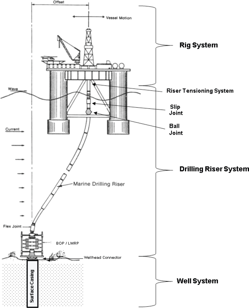
A marine drilling riser is an unpressurized conduit through which drilling operations can be conducted in deep water. It allows the passage of tubulars (such as drill pipe) drilling tools (such as drill bits) and drilling fluid.
For the purposes of this appendix, the drilling riser system includes
- The wellhead connector,
- The blow-out preventer (BOP),
- The LMRP, and
- The riser joints.
The drilling riser system interfaces with the wellbore system, which includes
- The surface casing and
- The soils in which the surface casing is set
The drilling riser system interfaces with the rig system, which includes
- The riser tensioning system
- The rig itself, including rig performance in various ocean environment conditions
Figure I.1 depicts a typical drilling riser system and its sub-systems and components.
FORCES ACTING ON A DRILLING RISER SYSTEM
Pressure
The pressure of water increases greatly at depth. Subsea equipment must be designed to operate in these high-pressure environments. Equipment in service on the sea floor, such as marine risers and BOPs, will see much more external pressure than equipment higher up, such as drilling riser connections.
For example, at 3,000 m (9,843 ft.) the water pressure is 4,400 psig (30.3 MPa). Any connections (e.g., the space in bolt threads) made up at the surface will likely have sea water intrusion into any tiny crevices, unless the material is hydrophobic.
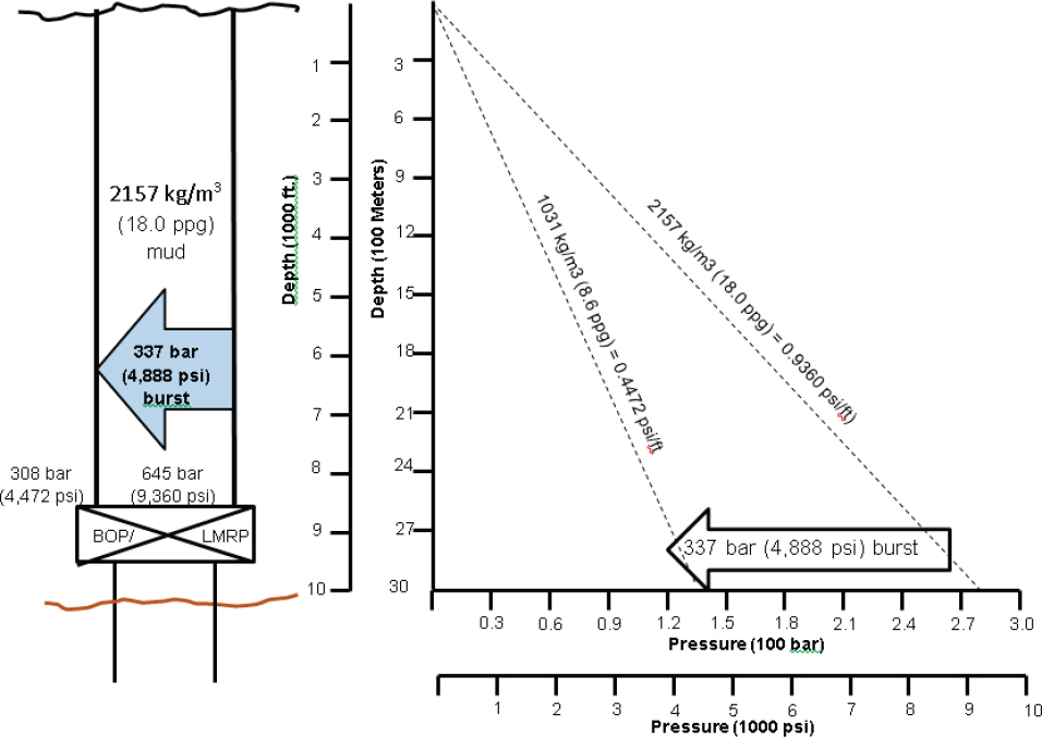
The design of subsea equipment must also consider the effect of differential pressure. The difference between the internal pressure and the external pressure is referred to as the “differential pressure.” During deep-water drilling, the mud density can be 2157 kg/m3 (18 ppg) or larger, while the sea-water density remains the same: 1031 kg/m3 (8.6 ppg). Figure I.2 demonstrates that, during drilling, the pressure differential is a positive 4,888 psi (33.6 MPa).1
The pressure differential affects the loads on the bolts of the flanged connections of the subsea equipment. For example an internal burst pressure can add to the tensile force on a connector in the following two different two ways:
- Piston effect due to pressure acting on an end cap or
- Pipe shortening due to ballooning of the pipe.
The pressure differential loads must be included incorporated in determining the bolt pre-load (among other load sources).
In deep-water operations, the sea-water pressure can approach 5,000 psi. (34.5 MPa) The pressure and temperature of the seawater at great depth should be considered when considering corrosion mitigation strategies for flanges and bolts, such as cathodic protection and protective coatings.
Currents
As stated in Appendix D, surface and subsea currents can be significant in the Gulf of Mexico. These currents can be created by the loop current, eddy currents that are spun off the loop current, and topographical Rosby currents.
___________________
1 Assuming seawater specific gravity of 1.032.
One of the most significant impacts on deepwater drilling and production riser design is that strong currents may occur at any time, from any direction in deepwater Gulf of Mexico—be it from the loop current, warm core eddy currents, or cold core eddy currents.
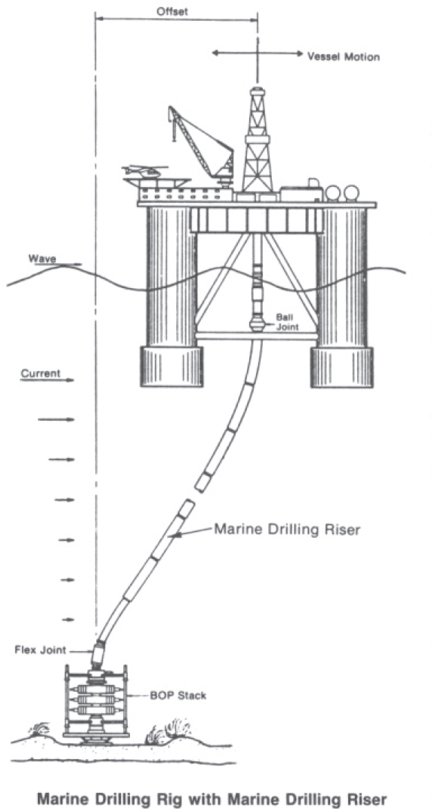
The loading these currents place on riser and BOP connectors is mainly riser displacement at depths where currents are sufficiently fast. The lateral displacement of the rig and riser caused by both waves and current will place a lateral load on the top of the BOP resulting is some seemingly minor displacement of the top of the BOP. This load will transfer as a bending moment to the wellhead connector and the wellbore casing through bottom BOP flange. This bending moment can be significant, and place tensile forces on bolts that are over and above the bolt preload. Figure I.3 depicts how currents can displace the rig and the riser.
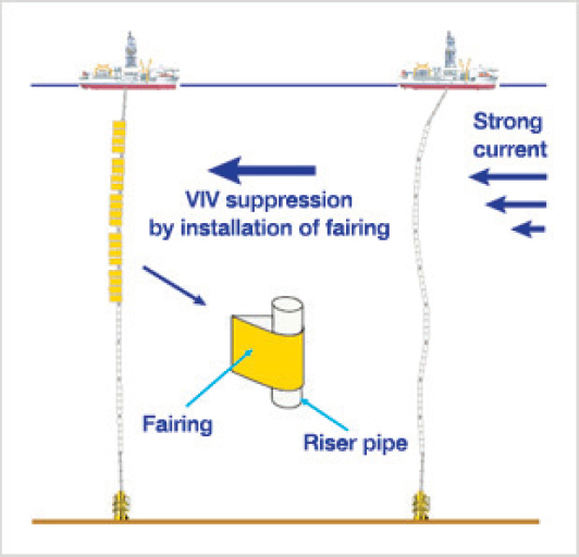
It is possible that currents could cause VIV (vortex induced vibrations), which might cause fatigue. Fairings (see Figure I.4) may be installed on risers to prevent VIV.
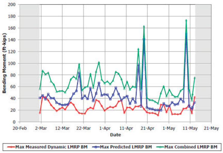
Figure I.5 shows the predicted and measured bending moments for the deepwater drilling operation that captured the current speed profile shown in Figure G.10 in Appendix G.
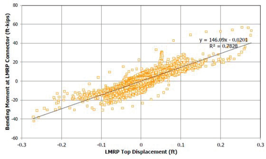
Figure I.6 shows the actual LMRP top displacement vs. actual bending moments, with a good correlation. In this case the bending loads were within the leak and structural capacity of the 10,000 psi API-18-3/4” flange, being used. It should be noted, however, that current speeds were only 1 knot at the surface. If the currents were as high as 4 knots, which can be caused by eddy currents, the bending moments would be higher.
Wind and Waves
Ocean surface wind and waves impact deepwater drilling operations in several ways.
- Wind speed and direction impact the amount and direction of lateral movement of the drilling rig, and resultant forces on the riser, the BOPs, and the wellhead connector. For drill ships, lateral movement can be somewhat mitigated by facing the ship into the wind.2 Wind speed and direction also affects the sea state. A constantly high wind coming from a consistent direction for an extended area can cause relatively high seas.
- Wave height impacts the heave (vertical movement) of the drilling rig. Unless extreme, any forces on the drill rig are mitigated by the riser slip joint at the top of the riser.
___________________
2 Bill Capdevielle, discussions with Jim Raney and Pat Boster, May 5, 2017.
3 Willard C. Capdevielle, discussions with Jim Raney and Pat Boster, May 5, 2017.
- Wave height, direction, and wave period impact the amount and direction of lateral movement of the drilling rig, and resultant forces on the riser, the BOPs, and the wellhead connector. For drill ships, lateral movement can be somewhat mitigated by facing the ship into the seas.3
- Wave period may impact fatigue life of drilling riser/BOP components, but only if the forces on the riser-BOP-wellhead are significant.
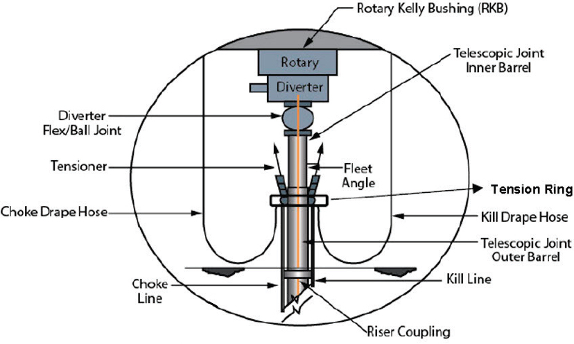
The analysis of the impact of wind and waves on riser/BOP loading need to take all these factors into consideration as they all occur simultaneously. To do this one needs to understand how the top of the riser is connected to the drill rig (or ship). Figure I.7 shows a typical riser top connection configuration. The riser is supported to the rig by tensioners that come down through the moonpool (the “hole” on the rig directly underneath the drill floor). The tensioners pull up on the riser to keep it in tension. This helps keep it straight and supports it against and current loading.
The tensioners may also pull up slightly on the BOP at the sea floor. For example, the rig tensioners may keep a 500,000 pound pull on the riser, 450,000 pounds will represent the buoyant weight of the risers and 50,000 pounds will be
tension pull on the LMRP.4 In this example, the tension could increase flange bolt tension in the LMRP over and above their preload.
In normal riser operations there is very little tension placed on the LMRP and BOP stack. It is only during abnormal situations (such as rig heave exceeding slip joint travel) that significant tension will be placed on LMRP and BOP flange connectors and bolts.
Buoyancy is considered in calculating riser weight. Riser buoyance is affected by the density of the fluid inside the riser and is therefore dependent on the drilling operations being undertaken at any given time. On very heavy risers buoyancy enhancement devices may be installed.5
The three pieces of equipment that manage riser tension during rig operations in response to movement induced by wind and waves are
- The rig tensioner system attached to the riser tensioner ring,
- The riser slip joint, and
- The riser flex joint (or ball joint).
___________________
4 Les Smiles, teleconference with Willard C. Capdevielle, May 18, 2017, presented to the committee on September 28, 2017.
5 API RP 16Q—Design, Selection, Operation, and Maintenance of Marine Drilling Riser Systems, Section 4.13.
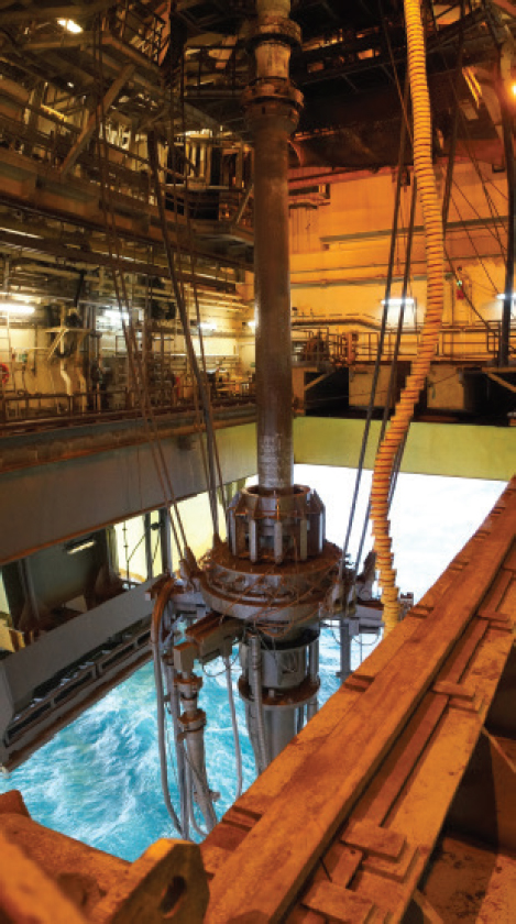
Figure I.8 is a photograph of riser tensioners coming down through the moonpool to hold the top of the riser, with an extended slip joint.
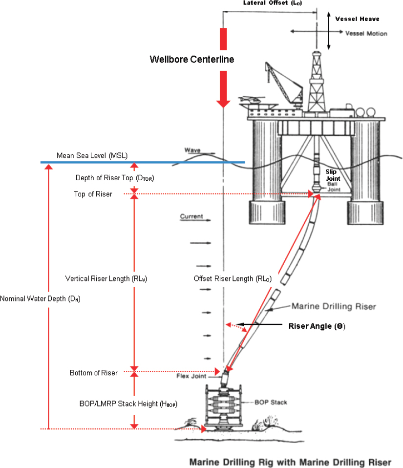
Consider this example of how rig heave and lateral displacement combine to potentially cause failure of the riser system. Refer to Figure I.9.
When offset is zero, then the length of the riser is the water depth (at mean sea level) minus the height of the BOP above the sea floor.
When wind, waves and current drive the rig off centerline the distance between the rig and the top of the BOP stack is increased slightly. This extra riser length is accommodated for by expansion of the slip joint(s).
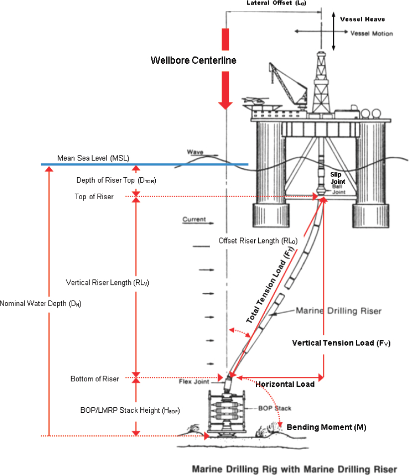
Taking this example a bit further, if the slip joint bottoms out a lateral force will be placed on the BOP/LMRP. This will be in addition to the tensile load placed
on the riser system. Refer to Figure I.10. This lateral force will produce a bending moment (MLF) will be created according to the formula:
MLF = FH HBOP
where MLF = bending moment due to lateral force
FH is the horizontal load on the riser just prior to riser failure
HBOP is the vertical distance between the sea floor and the bottom of the riser
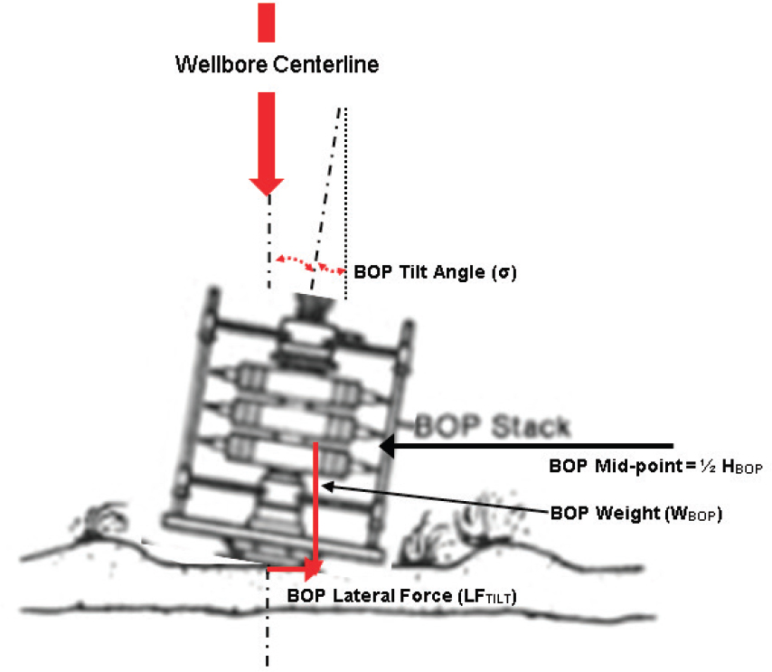
One more potential complication is BOP tilt. Refer to Figure I.11. BOP tilt can occur because of
- The well’s casing being installed a bit off vertical, and/or
- The surface casing, being set in soft mud and being pulled off center by currents acting on the riser.
BOP tilt can cause a small bending moment (MTILT) due to the high weight of the BOP/LMRP stack.
BOP Testing
BSEE requires that BOPs be tested every 14 days. Part of a BOP test is the pressure test program. BOPs are tested at a low pressure (several hundred psi) and at high pressure. The high-pressure test must be performed at rater working pressure (RWP) or 500 psi greater than anticipated maximum service pressure (MASP).
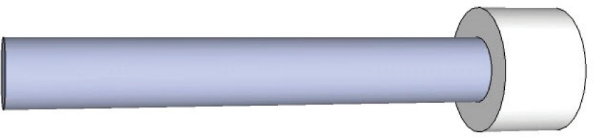
During these pressure tests all pressure sealing rams and annulars are closed and pressure is applied through the choke line or the kill line. For non-blind rams and annulars, a test tool (see Figure I.12 at right) is on the drill pipe. The outer surface of this test tool is sized to fit the “hole” n pipe rams. It also provides a surface on which the annulars can close.
The plug at the bottom of the test tool rest against the bottom of the pipe rams or the annular as the pressure below it acts like a piston trying to push up on the test tool.
The test pressure between BOP components creates a tensile load on the flanges between the components. This force is the test pressure times the bore area of the component being tested.
This tensile load is transferred to the flange bolts in proportion to the bolt-to-flange stiffness. This load is in addition to the bolt preload.
Tension/Compression Cycles
In normal operations there is no significant compression loads on the riser system. Flange ring gaskets will experience normal compression loads due to flange bolt pre-loading. Unless flange bolts are pre-loaded to highly, ring gasket compression should be within design limits.
Tension in the bolts will be created by
- Bolt preloading,
- Internal pressure loads (such as pressure testing BOPs, or heavy fluids in the riser),
- Tension being pulled on the riser by the rig, and
- Bending moments on the flange connector.
DRILLING RISER SYSTEM DESIGN PROCESS
The purpose of a riser system design effort is to ensure that a drilling riser system can be successfully constructed, deployed, and operated to enable safe drilling of a well. Although this section deals with design techniques for a complete riser system, the design and construction of components must have been performed prudently so they will perform as required by the riser system. API RP 16Q states, “The marine drilling riser is best viewed as a system. It is necessary that designers, contractors, and operators realize that the individual components are recommended and selected in a manner suited to the overall performance of that system.” It is for just this reason that this appendix will discuss overall riser system analysis processed before delving deeper into the design processes for flanges and flange bolts.
Because of the complexity of the design and operation of a drilling riser system, API RP 16Q presents several types of design methodologies that can be used at the discretion of the lease operator, the drilling contractor, a drill rig shipyard, or the OEM.6 The most common are
- Operability analysis,
- Failure analysis, and
- Fatigue analysis.
Additionally API RP 16Q describes methodologies for
___________________
6 API RP 16Q—Design, Selection, Operation, and Maintenance of Marine Drilling Riser Systems, Chapter 5.
- Recoil analysis and
- Disconnected riser analysis.
The first three design methodologies will be discussed below.
Operability Analysis
Operability analysis is performed that a riser of a specific design can be safely deployed and operated on a specific rig, in a specific location, during a set of anticipated drilling/wellbore conditions, and under a set of assumed environmental conditions. This analysis is done to ensure the following:
- Riser can be safely run and retrieved,
- Riser can stay connected to allow safe drilling,
- Riser (LMRP) can be connected, disconnected, and re-connected,
- Riser/LMRP can be safely “hung off” the tensioner system after LMRP disconnection—until the riser can be pulled or re-connected, and
- Rig is suitable for the riser (rig tensioning system capability, moonpool configuration, DP capability).7
There are a series of weight and size analysis that are done regarding deploying a specific riser system. However the main thrust of the operability analysis is to communicate to the drilling contractor conditions under which the LMRP must be disconnected from the lower BOP stack to protect the structural integrity of both the riser system and the well. This is called the “drive-off/drift-off analysis.”8
The analysis is made using a certain set of assumptions. These assumptions include ocean conditions and weight of the mud in the drilling riser. Riser system parameters evaluated include the following:
- Flex/ball joint angles,
- Tensioner stoke,
- Telescopic joint stroke,
- Riser stresses, and
- Wellhead and casing loads.
___________________
7 Kenneth Bhalla, discussions with Willard C. Capdevielle held on July 13, 2017, presented to the committee on September 28, 2017.
8 API RP 16Q—Design, Selection, Operation, and Maintenance of Marine Drilling Riser Systems, Section 5.5.
This analysis establishes operational limits for the riser to be deployed. The primary operational limits are as follows:
- Maximum tension setting (TMAX)—defined in API RP 16Q as “the highest permissible tension setting with the vessel on location that provides sufficient margin so that anticipated conditions (such as wave-induced vessel motions, rig excursion, and/or tide change) do not cause any tensioner system relief valves to open, cause the tension experienced in the tensioners to exceed the limits of the design, or cause the pressure in the tensioners to exceed the limits of the design. With these considerations in mind, tension on any individual tensioner should not exceed this limit and the maximum tension setting for the riser, TMAX, should not exceed this limit multiplied by the number of active tensioners. Other considerations (e.g., riser and wellhead loading, recoil, etc.) may impose additional restrictions on tension setting.”
- Minimum top tension (TMIN) —defined in API RP 16Q as “the minimum top tension required to prevent global buckling of riser in the event of the sudden loss of pressure in a tensioner or tensioner pair. The tension setting should be sufficiently high so that the effective tension is always positive in all parts of the riser even if a tensioner should fail. In most cases, the minimum effective tension is encountered at the bottom of the riser. In some cases, the minimum effective tension may occur at another location.”
- Maximum lateral offset—the maximum rig lateral offset that can be tolerated without causing mechanical failure of the riser or any of its components by excessive tension or bending moment. Since lateral offset is the primary cause of so many failure modes for a riser/BOP system it is critical that it be accurate, conservative, and adhered to in the field. This operational limit is usually documented by a “watch circle.”
The watch circle concept imposes an important safety operational limit. In practice, three (3) watch circles are established as depicted in Figure I.13.9,10,11
In practice, three watch circles are established:
- The point of disconnect (POD) circle is the first circle to be calculated. This is the maximum lateral offset that can be tolerated by the riser system and its
___________________
9 Les Smiles, teleconference with Willard C. Capdevielle held on May 18, 2017, presented to the committee on September 28, 2017.
10 Kenneth Bhalla, discussions with Willard C. Capdevielle held on July 13, 2017, presented to the committee on September 28, 2017.
11 API RP 16Q—Design, Selection, Operation, and Maintenance of Marine Drilling Riser Systems, Section 5.5.
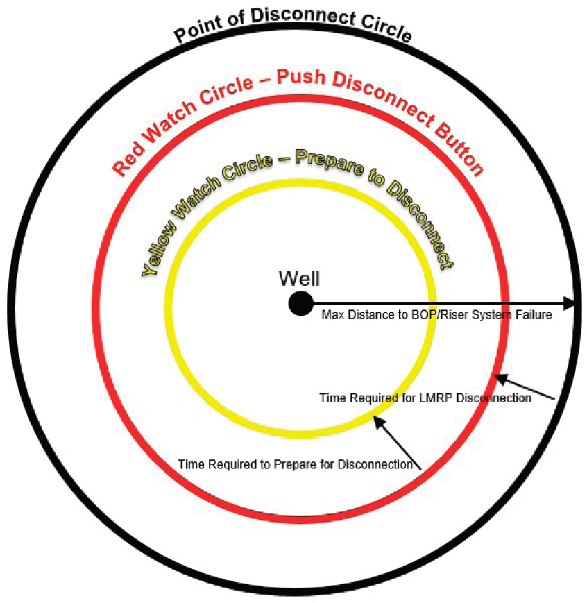
- components without a mechanical failure at some point in the riser system. As a rig moves towards the POD limit:
- Ball joint is maxed out,
- Tension increases due to riser length at angle,
- The riser slip joint strokes out,
- The riser tensioning system reaches its lower limit,
- Tension is added to riser top,
- Bending moment on wellhead and BOP results, or
- Current could add or subtract a small amount.
- The only way to prevent such a failure is to disconnect the LMRP for the lower BOPs, this unbounding the bottom of the riser string.
- The red watch circle is calculated from the POD Circle. It represents the largest lateral offset at which the disconnect sequence should begin (i.e., the “red button” is pushed). This disconnect sequence includes operations such as closing BOP rams. The sequence may take 1 to 3 minutes, depending on the BOP.
- The yellow watch circle is calculated from the red watch circle. It represents the largest lateral offset at which preparations for a disconnect should begin. These preparations may include things like pulling the drill bit off bottom to prevent it from being stuck by falling cuttings, or spacing out the drill pipe to ensure no tool joints are across the BOP shear ram(s). Spacing out in deepwater takes some time. There are critical human factors considerations here in determining the time for individual drilling crews to make these preparations.
The following observations about the watch circle should be noted:
- The condition that results in the most conservative calculation of the POD circle is the condition where the riser telescopic joint strokes out and outer barrel/tension ring is at its lowest elevation in the moonpool.
- Regarding the red and yellow watch circles, API RP 16Q states: “Both determinations rely on many assumptions about the vessel’s trajectory (change in offset and heading versus time) as well as the time required to recognize and respond to the drive-off or drift-off, prepare for emergency disconnect, for the emergency disconnect to complete, and for the LMRP to separate from the lower stack prior to reaching a maximum allowable point of disconnect (POD).” In other words, there are some uncertainties in the calculation of the red and yellow watch circles:
- There is an assumed speed at which the rig offset is occurring. Watch circles are predetermined and are not adjusted for real-time vessel offset. Some companies specify the use of the 1-year winter storm (concurrent wind and waves) for disconnect time calculations.
- The activities included in “preparations for a disconnect” may vary for each rig and for different drilling operations being performed.
- The time to “recognize and respond to the drive-off or drift-off” situation is very dependent on the driller on the rig floor. This time is very dependent on the “human system.” Operators or drilling contractors usually provide this information to the riser design engineer. The committee found no evidence that this time was benchmarked by training or drills.
-
The POD circle is calculated on a set of assumptions. The POD circle is not updated for
- Actual wind, waves, and surface currents;
- Actual rig responses to wind and waves (heave, pitch, and roll; the “bottoming-out” of riser slip joints is influenced mainly by rig heave and lateral offset; neither of these parameters are used to update the POD circle);
- Actual riser position (angle) which can be measured, but not captured real time unless special equipment is on board;
- Actual underwater currents which can be measured by Acoustic Doppler Current Profilers (ADCP)12 and were required by MMS NTL No. 2009-G02 to be measured and reported to the National Data Buoy Center. However this data is seldom used to update watch circles; and
- Actual loads or positions of riser components such as bottom flex/ball joints or flange bolts.
Failure (Weak Point) Analysis
Failure analysis has only one purpose: to evaluate all components of a drilling riser system as designed, manufactured, deployed, and operated and to ensure that if a failure occurs it will occur ABOVE the BOP. In other words, weak points in the riser system are calculated and the likely first component to fail is identified. A weak point failure below the BOP would disable the ability to control the well and a blowout would likely occur. This would require a re-design of the riser system. If the ability to disconnect (as assured by the watch circles) is the first line of defense, failure analysis is the second (and final) line of defense.
The assumptions that go into the calculation of the POD watch circle will also go into the failure analysis. Similarly the uncertainties go into the calculation of the POD watch circle will also go into the failure analysis.
However the riser designer must use their judgement in selecting worst and best case parameters to account for design uncertainties. For example, while POD circle calculations are most conservative when the riser slip joint strokes out and outer barrel/tension ring is at its lowest elevation, for weak point considerations the operating situation that results in the least amount of extension of the telescopic joint and the barrel/tension ring is at its highest elevation in the moonpool will typically be conservative. This is “because the eventual bottoming out occurs at a larger offset thereby producing larger bending moment and stresses.”
___________________
12 NOAA, Ocean Explorer, “Acoustic Doppler Current Profiler,” http://oceanexplorer.noaa.gov/technology/tools/acoust_doppler/acoust_doppler.html, accessed October 22, 2017.
And again, because much of the real-time performance of the riser system and its components are not measured real time, the likely point of failure cannot be updated for real-time condition.
Fatigue Analysis
It is interesting that fatigue analysis has been the least-accepted design effort by industry. Perhaps this is because there was a perception that the higher frequency load cycles due to rig heave resulted in relatively low stress levels. These higher frequency, lower-load conditions were
- Wave motion and lateral rig movement;
- Tension load cycles due to rig heave, which may occur if the riser tensioning system is not operating properly; and
- Vortex-induced-vibration (VIV) caused by surface currents that was thought be a near surface phenomenon that could be mitigated by increasing riser tension at the surface or by placing fairings on the shallow portion of the riser.
In the past, the high-load events that drove fatigue were considered to be the routine bi-weekly pressure testing of BOPs. Recent developments have indicated that riser system and component fatigue life can be finite in the dynamic ocean environment. Fatigue is most likely driven by ocean currents.13 It is now known that there is the potential for significant currents to exist at all depths in a deepwater location. Eddy currents exist from the surface down to depths of 1,000 m (3,300 ft.). This has been confirmed by field measurements using Acoustic Doppler Current Profiler (ACDP). Figure D.12 in Appendix D shows the result from one such ACDP reading. In addition, in deepwater Gulf of Mexico locations near the Sigsbee Escarpment, Rossby Waves can produce significant currents near the seafloor.
Interestingly these is no requirement to analyze fatigue for deepwater riser systems except for HPHT wells, although fatigue can be a bigger issue in shallower water The definition for “HPHT” can be found in API TR8.14
Fatigue analysis looks primarily at the conductor pipe, the wellhead and wellhead connector, and the riser string. Because it is so stout, fatigue analysis is not
___________________
13 Les Smiles, teleconference with Willard C. Capdevielle held on May 18, 2017, presented to the committee on September 28, 2017.
14 Brian Healey, Ph.D., and Partha Sharma, discussions with Bill Capdevielle held on July 7, 2017, presented to the committee on September 28, 2017.
performed on the BOP/LMRP or its components.15,16 It is important to consider the conductor pipe, wellhead and wellhead connector for the following reasons:
- These are the components that bound the bottom of the riser thus cyclic loading from the riser will be transmitted these components, although likely dampened.
- These are permanent components of the well. They must survive for the entire lifetime of the well, form well construction to well abandonment. The effects of fatigue are cumulative. The fatigue life of these permanent components must be managed expeditiously.
- These components are situated below the BOP during well construction and below the subsea tree during production. Failure would likely result in a catastrophic well control event.
There is ongoing research into the VIV phenomenon. This includes methods for real-time measurement, methods for the real-time analysis of this data, and better fatigue life prediction methods.17,18,19
___________________
15 Ibid.
16 Kenneth Bhalla, discussions with Willard C. Capdevielle held on July 13, 2017, presented to the committee on September 28, 2017.
17 S.I. McNeill and P. Agarwal, “Efficient Modal Decompression and Reconstruction of Riser Response Due to VIV,” OMAE2011-49460, 30th International Conference on Ocean, Offshore and Arctic Engineering, June 19-24, 2011, http://proceedings.asmedigitalcollection.asme.org.
18 S. McNeill, P. Agarwal, D. Klok, K. Bhalla, T. Saruhashi, I. Sawada, M. Kyo, E. Miyazaki, and Y. Yamazaki, “Real-Time Riser Fatigue Monitoring Routine: Architecture, Data, and Results,” OMAE2013-11540, 32nd International Conference on Ocean, Offshore and Arctic Engineering, June 9-14, 2013, http://proceedings.asmedigitalcollection.asme.org.
19 S. McNeill, T. Saruhashi, I. Sawada, M. Kyo, E. Miyazaki, and Y. Yamazaki, “A Method for Estimating Quasi-Static Riser Deformation and Applied Forces from Sparse Riser Inclination Measurements,” OMAE2015-41286, 34th International Conference on Ocean, Offshore and Arctic Engineering, May 31-June 5, 2015, http://proceedings.asmedigitalcollection.asme.org.


