
2
Assessment of Critical Subsea Bolting System Design Elements
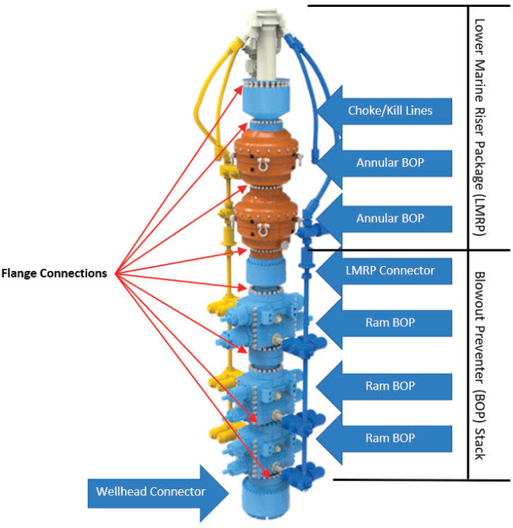
For purposes of this study, only bolted flange connectors are considered—more specifically, the connectors for closure bolting of pressure containing flanged connections or assemblies which will also be subjected to mechanical loads such as tension and bending. Figure 2.1 shows bolted connections used on a typical subsea blowout preventer (BOP) stack assembly. Bolting is used on the flanged connections between BOP rams, the flanged connectors between the lower BOP stack and the Lower Marine Riser Package (LMRP), and the flanged connectors between LMRP and the flexible ball joint and riser. Bolting is also used on the rams, such as the blind shear ram housing (on which, as stated elsewhere in this report, failures have occurred). Based on the limited data and general information that the committee has reviewed, the committee has seen little or no evidence of any bolt failures attributable to cyclic loading or fatigue.
A critical connection is defined as one which if it failed would result in the release of hydrocarbons and drilling fluids to the environment. Similarly, critical bolting, in this context, is a bolt, stud, nut or fastener used on a critical connection. There are approximately 850 critical bolts, studs, and nuts on a deepwater 7-ram BOP stack; this includes both the LMRP and lower BOP stack assemblies. A flanged drilling riser deployed in 6,000 ft. of water has an estimated 450 bolts plus 450 inserts (nuts).”1
___________________
1 K. Armagost, Anadarko Petroleum Company, “Root Cause Failure Analysis, In Support of Improved System Reliability,” presentation to the Workshop on Bolting Reliability for Offshore Oil and Natural Gas Operations, April 11, 2017.
Throughout this chapter, drilling risers are mentioned since they protect the drill string which is part of the pressure boundary, and employ fasteners in many applications. Appendix I is a tutorial on the design of a drilling riser. It begins with a discussion of the many forces that act on a drill riser system, and supplements the discussion in Appendix G, “Subsea Environmental Factors for Fastener Design.” The appendix reviews the drilling riser system design process, operational analysis, failure (weak point) analysis and fatigue analysis. This appendix is intended as background and context to this chapter’s discussion and analyses.
FASTENER DESIGN
Nomenclature
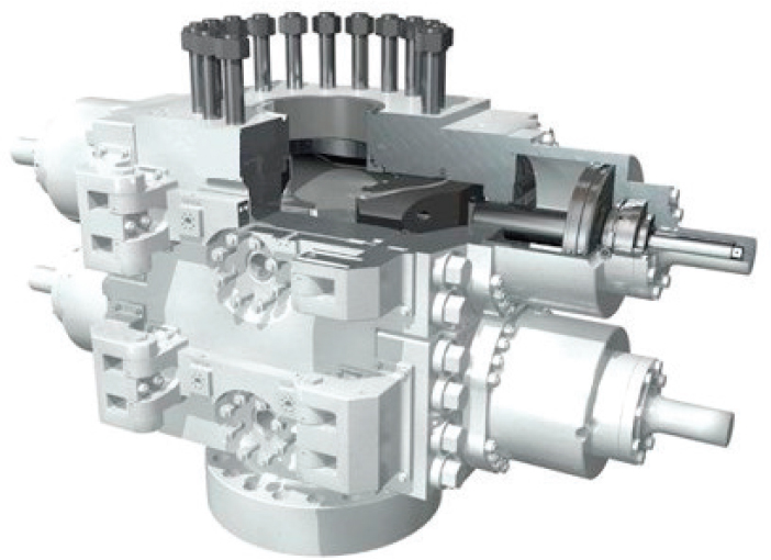
A simplified schematic depiction of a section of a subsea BOP, exhibiting a bolted flange connector and shear ram actuator housing is shown in Figure 2.2. The assembly includes among other components: flanges, ring gaskets, and multiple flange bolts, studs and nuts. The number of flange bolts and the size and strength of the bolts, studs, and nuts depends primarily on the flange size, seawater depth, and drilling or production fluid pressures and temperatures. Note that the threaded fasteners on the flanges and ram housing are of a variety of types, sizes, materials, and strengths. The threaded fasteners also require different makeup torques and possibly assembly tools.
Figure 2.3(a) shows a sketch of an LMRP hydraulic connector from the Bureau of Safety and Environmental Enforcement (BSEE) QC-FIT Evaluation of Fastener Failures—Addendum report. During assembly, torque is applied to the bolt head, or nuts, to compress the flanges faces and generate compressive stress on the seal
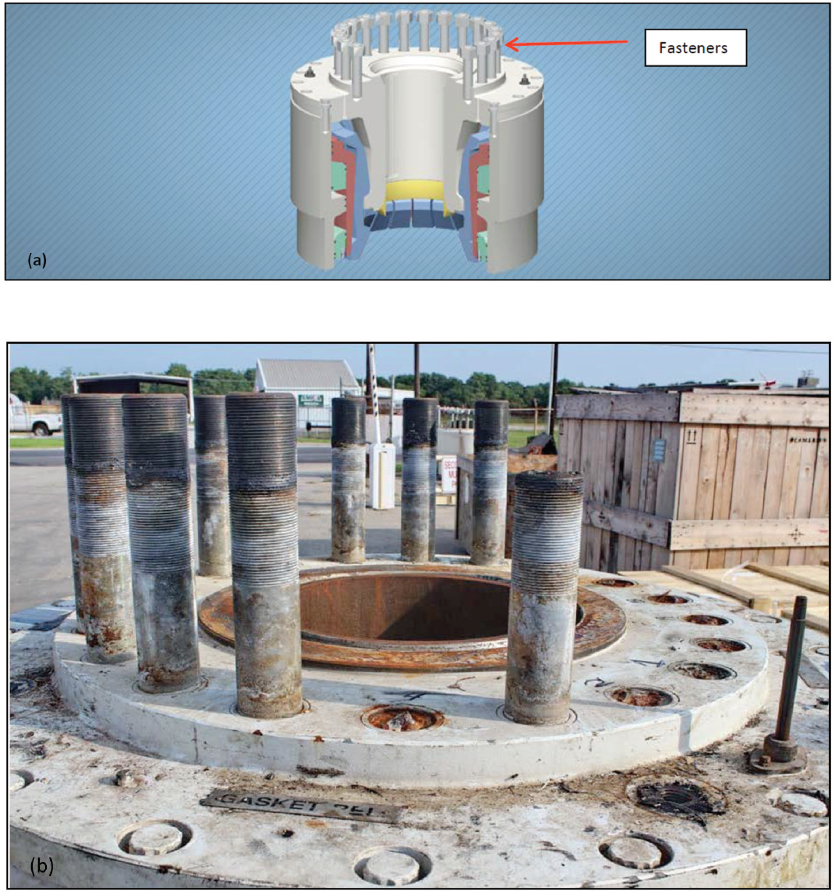
ring faces. As the flange and seal ring faces are compressed, the bolts are stretched, resulting in longitudinal tensile stresses in the bolts. As is well known, the thread roots create a stress concentration, with the first engaged thread root generally having the largest local tensile stress. It can be clearly seen in Figure 2.3(b) that threads failed at the first engaged thread at the flange face. As can also be seen in the photo of the failed connector, a cluster of bolts failed, but not all of them.
Operational Loads on Flange Bolts
Because of the subsea environment, varied and dynamic forces act on the flanged connections in the subsea riser equipment and the threaded fasteners therein. Basic design considerations for bolted connection (i.e., flanges and housing) design include the following:2
- Flange and seal ring compressive stress
- Bolting preload tension stress (currently based on torque)
- Flange stiffness or rigidity under load
- Bolt spacing
- Material selection for strength and environmental compatibility
- Service loading during drilling, production, installation (running)
- Environmental loading (sea states, currents, storms, etc.)
- Corrosion resistance through coatings, impressed voltage,
- Fatigue
Bolted flange connectors used in a subsea riser system, including the BOP/LMRP and wellhead connector, are subjected to several types of loads:
- Compression loads due to the net buoyant weight of the BOP stack and riser.
- Tension forces due to the loads transmitted by the drilling riser and floating platform, drilling operations, or during the running or retrieval of drill pipe.
- Bending loads due to lateral movement of the rig and riser and ocean currents.
- Bending on the LMRP and BOP are reduced by the upper and lower flex joints (discussed further in Appendix I).
- The bending loads transmitted to the subsea BOP system, however, will impart tension (on the high side) and compression (on the low side) on the flange and bolting.
___________________
2 Ramón I San Pedro, PE, “Bolted Flange Joints in Offshore: Basic Principles and Applications,” presentation to the committee on March 22, 2017.
The design of American Petroleum Institute (API) wellhead and BOP flange connectors could, in theory, sustain its rated pressure, despite a limited number of bolt failures. The committee does not know if this theory has ever been verified by modelling or testing a flange connection with one or more bolts failed. However, the failure of any one bolt reduces the inherent reliability of the flange since the service loads are transferred to adjacent bolts, leading to the potential for subsequent bolt failure on the flange. This could lead to cascading bolt failures.
The committee found a general lack of concern by the industry about single bolt failures, as evidenced by the lack of any industry wide tracking of these failures until mandated by BSEE. This apparent lack of concern is troublesome, since the committee had no access to statistical data or engineering studies regarding the effect of single bolt failures on overall flange connector reliability under a variety of loading and environmental conditions. As discussed later in this report, considering the past occurrence of multiple bolt failures in the same connector, the failure of any bolt in critical service warrants a full root cause analysis to reduce the potential for future failures. It is important not to risk a false sense of security by the bolt redundancy designed into bolted connectors, particularly when they have demonstrated an ability fail in clusters or groups.
Bolt preload considerations are important and are discussed in greater detail in Chapter 3 and in Appendix J.
Bolt Preloading
Flange bolts are “preloaded” during flange assembly. Bolt heads or nuts are torqued to apply tension on the bolts which then compresses the flange faces to attain structural integrity and pressure containment which the preload should maintain in the face of all other loading. The preloading of bolts is a critical operation because of the high stresses placed on the bolts and the requirement for the bolts to accommodate any additional operational loads imparted on the connector.
Current oil and gas industry practice or preloading flange bolts using torque has been shown to have an accuracy preload variability of ±25 percent to 30 percent.3,4,5 To the best of the committee’s knowledge, bolt preload variability is not accounted for in bolt and connector design; this is of concern to the commit-
___________________
3 K.H. Brown, C. Morrow, S. Durbin, and A. Baca, Guideline for Bolted Joint Design and Analysis: Version 1.0, SAND2008-0371, Sandia National Laboratories, Albuquerque, N.M., January 2008.
4 L. Burgess, discussions with Nancy Cooke and Bill Capdevielle on May 31, 2017, presented to the committee on August 28, 2017.
5 J.H. Bickford, An Introduction to the Design and Behavior of Bolted Joints, Third Edition, Marcel Dekker, Inc., New York, N.Y., 1995.
tee. Bolt preload is a critical design parameter, and is discussed in greater detail in Appendix J.
Fastener Material Selection
Material and quality specifications are an important part of any design process. Threaded fasteners for offshore applications are manufactured according to specifications6,7 including API Spec 20E, “Alloy and Carbon Steel Bolting for Use in the Petroleum and Natural Gas Industries,” and API Spec 20F, “Corrosion Resistant Bolting for Use in the Petroleum and Natural Gas Industries.”8,9 Each of these API specifications details the requirements for materials, properties, manufacturing, testing, inspection, and recording keeping. Three quality levels, referred to as bolting specification levels (BSLs) are identified in API Specs 20E and 20F. The higher-grade levels, particularly BSL-3, are of primary interest for connectors in critical offshore applications. Each specification also references American Section of the International Association for Testing Materials (ASTM) and API documents that identify material compositions and grades covered by each standard. As examples, common steels produced according to API Spec 20E include heat treated, nominally 0.4 weight percent carbon steels such as American Iron and Steel Institute (AISI) standards 4140 and 4340. Examples of corrosion resistant alloys (CRAs) produced according to API Spec 20F include the high nickel superalloy, Alloy 718, and selected alloys similar to stainless steels.10,11 As the majority of the threaded connectors in service are heat treated medium carbon steels, the comments below concentrate on those types of steels. Selected comments specific to nickel base and CRAs are also presented.
The types of threaded steel connectors of interest for offshore applications are contained in Section 3.1.1 of API Spec 20E and include the following: all-thread
___________________
6 Det Norske Veritas (DNV), JIP—Guideline for Specification, Design, and Assembly of Offshore Bolted Joints, Report No./DNV Reg No. 2008-1656/1201FBR-56, Rev, 1 2012-06-11, Høvik, Norway.
7 B. Lillebø, “Bolting Materials Subsea,” presentation at the Materials in Offshore Constructions, Esbjerg, June 2, 2006, Det Norske Veritas, Bergen, Norway, http://www.offshorecenter.dk/log/filer/1_7%20DNV.pdf.
8 American Petroleum Institute (API), Alloy and Carbon Steel Bolting for Use in the Petroleum and Natural Gas Industries, API Specification 20E, Second Edition, Washington, D.C., February 2017.
9 API, Corrosion Resistant Bolting for Use in the Petroleum and Natural Gas Industries, API Specification 20F, First Edition, Washington, D.C., June 2015.
10 API, Age-Hardened Nickel-Based Alloys for Oil and Gas Drilling and Production Equipment, API Standard 6A718, Draft Copy of Third Edition, April 2013, Washington, D.C.
11 ASTM International, Standard Specification for High-Temperature Bolting, with Expansion Coefficients Comparable to Austenitic Stainless Steels, ASTM Standard A453, West Conshohocken, Pa., 2017.
studs, tap-end studs, double-ended studs, headed bolts, cap screws, screws, and nuts.
VARIABILITY OF BOLTING LOADS
The dynamic loading on the drilling riser systems, which includes the LMRP/BOP systems and critical bolting, has been an active area of research. Since the riser system can impart tensile, compressive and bending loads on the BOP system and its critical bolts, riser dynamic loading should not be ignored or its importance minimized. Real-time measurement and analysis of stresses and deflections of risers was presented in, for example, Tognarelli et al., 2008.12 In addition, Fleece presented sea current profiles and resulting bending moments on an API 18-3/4” LMRP connector flange in the workshop on April 11, 2017.13
The potential for sea states to cause fatigue due to dynamic loading of risers is an important subject of interest to the deepwater drilling and production industry. The committee has not been provided with any data that provides evidence of failures attributable to cyclic loading and fatigue. However, QC-FIT evaluations have shown that industry understands very little about the impact of cyclic fatigue on riser components such as bolts. For example, fatigue loading does not appear to have been responsible for reported failures summarized in Appendix E.
Rather, the evidence of the several cases presented to the committee appear to be environmentally assisted intergranular brittle failure of bolting in flanged connections, and a few cases of what appeared to be ductile overload failures on a blind shear ram actuator housing. To be clear, the committee notes that concurrent presence of static tensile load and low frequency cyclic loading can produce hydrogen-assisted intergranular cracking at reduced static threshold stress intensities below those observed in purely static loading. This only occurs as long as hydrogen was present from the gas phase or aqueous charging of hydrogen. The committee wishes to note that this differs from dry fatigue in the absence of charged hydrogen and is due to enhanced hydrogen uptake and hydrogen dislocation, or fracture process zone interactions, which enhance susceptibility to hydrogen-assisted cracking (HAC).
API Specification 17D, “Specification for Subsea Wellhead and Christmas Tree Equipment” which also applies to subsea BOPs, specifies bolt loading limits as a percentage of yield stress (not ultimate tensile strength), because plastic deforma-
___________________
12 M.A. Tognarelli, S. Taggart, and M. Campbell, “Actual VIV Fatigue Response of Full Scale Drilling Risers: With and Without Suppression Devices,” Paper OMAE2008-57046, Proceedings of the 27th International Conference on Offshore Mechanics and Arctic Engineering (OMAE2008), American Society of Mechanical Engineers, New York, N.Y., 2008.
13 T. Fleece, BP, “Mitigating BOP Failures,” presentation at the Workshop on Bolting Reliability for Offshore Oil and Natural Gas Operations, April 11, 2017, p. 17.
tion of bolts is as undesirable an event as an actual bolt failure if it leads to failure of the connector to maintain the pressure boundary of the well.
The yield margin of safety for flange bolts can be derived from the working stress limitations specified in API Spec 17D, which recommends the following:
- For bolt preload (the initial “tightening of a flange bolt to achieve flange face closure force), the bolt should be placed in a tensile loading state of 67 percent to 73 percent of the yield stress.14
- For bolt in-service loading (the bold preload plus any additional working loads such as pressure, externally applied tension, or bending moments on the connector) the tensile loading on the bolt shall not exceed 83 percent of the yield stress.15 Assuming that the torque values are ±30 percent, the yield margin of safety is .205; Appendix J contains more details on yield margin of safety and margin of safety.
Subsea wellhead and Christmas tree bolts suffer additional and greater integrity risks, including:
- Service in high-pressure salt water—sometimes hypersaline
- Exposure to H2S, CO2, hydrogen, and cathodic protection
- Potential tensile forces coming from the rig through the riser
- Potential bending moments caused by deep water currents
The above four factors place significant and often uncertain environmental stress and loading on subsea bolts. This operating environment of subsea critical bolts raises questions about the appropriateness of the yield margin of safety implied by API Spec 17D even though no failures due to inadequate yield margin of safety were reported to the committee.
More information on flange bolt loading can be found in Appendix J.
FASTENER LIFE CYCLE
Bolt Manufacturing
The manufacture of threaded fasteners begins with the production of cylindrical rods (typical diameters of 25 to 150 mm). This section highlights details of the production processes followed by assessments of installation and service life considerations.
___________________
14 API, API Specification 17D, ISO 1 3628-4, 2nd Edition, May 2011, Section 5.1.3.5, p. 19.
15 API, API Specification 6A, ISO 10423:2009 (Modified), 20th Edition, October 2010, Section 4.3.4, p. 28.
Multiple different processing routes are available to produce heat-treatable steel alloys, nickel-based superalloys, and other CRAs as wrought bar products for use in the production of offshore industry connectors. As reviewed previously,16 steel alloys are first synthesized in liquid form and solidified in either ingot or continuous casting form. As a direct consequence of solidification, alloy elements redistribute during the cooling process to form regions of micro-segregation within the solidified microstructure producing alternating zones of high and low alloy content. As a result of shrinkage associated with solidification, internal porosity can also develop. The integrity and properties of steel bars which are the feed stock for the manufacture of finished connectors depend on multiple variables including initial alloy content and cleanliness along with thermal and deformation history. Production of defect-free steel bars with homogeneous chemical composition and microstructures is ideal.
In ingot casting facilities, individual ingots with cross sections in excess of 1 m2 are typically produced. Prior to rolling or forging, ingots are heat soaked (i.e., heated and held at an elevated temperature for a long period of time) to facilitate alloy homogenization by diffusion and to produce ingots with a uniform temperature throughout the cross sections. Depending on the facility, the ingot cross sectional area is first reduced in a blooming mill (“bloom” refers to an intermediate semi-finished bar) prior to further reduction by rolling to a form a billet (note that the difference between a bloom and billet is somewhat arbitrary and relates to size).17 In continuous casting facilities, steel is solidified directly as a continuously moving billet with typical section sizes up to about 18 cm × 18 cm square.18 Recently continuous casting systems have been developed which produce jumbo blooms with larger section sizes up to about 45 cm × 61 cm19 and these systems may include an in-line forging system prior to rolling to billets. However, API 20E currently prohibits the use of continuous cast product in the production of BSL-3 connectors.20
Round bars are produced by hot rolling billets through multi-stand bar mills with reductions per pass and pass geometries carefully selected to produce the de-
___________________
16 G. Krauss, “Solidification, Segregation and Banding in Carbon and Alloy Steels,” presented at the Howe Memorial Lecture, ISS, April 2003, and published in Metallurgical and Materials Transactions B 34B:781-792, 2003; also published in AIST Transactions, Iron and Steel Technology 1(3):145-157, 2004.
17 W.T. Lankford, N.L. Samways, R.F. Craven, and H.E. McGannon, eds., The Making, Shaping, and Treating of Steel, 10th edition, Association of Iron and Steel Engineers, Pittsburgh, Pa., 1985.
18 B. Kozak and J. Dzierzawski, “Continuous Casting of Steel: Basic Principles,” http://www.steel.org/making-steel/how-its-made/processes/processes-info/continuous-casting-of-steel---basic-principles.aspx, accessed May 2017.
19 P. Anderson, “Forging Quality in Steel Ingot Manufacturing & Conversion,” presentation at Forge Fair 2015, April 15, 2015, TimkenSteel, Ohio, http://www.timkensteel.com/what-we-know/resource-library.
20 API Spec 20E.
sired final diameter bars required for connector manufacture. For threaded studs machined from as-supplied rolled rod, often the final rod is provided in the cold rolled or an intermediate heat-treated condition, where cold finished bars have a higher dimensional tolerance than hot rolled products. In contrast to the production routes summarized above for heat treatable medium carbon steels, high alloy materials (e.g., austenitic nickel based alloys and CRAs) often are melted in vacuum furnaces, cast to ingots, and reduced by radial forging to rounds for use as finished products or as feed to subsequent rolling operations.
During hot working (i.e., forging or rolling), internal porosity present after casting is eliminated and regions where micro-segregation is present, are deformed and aligned with the rolling direction producing compositional bands. On cooling or during subsequent thermal processing, the composition bands may lead to microstructural variations with wavelengths on the order of microns. The resulting microstructural variations lead to a feature referred to as “banding.”21 Significant improvements in steel making technology have evolved to produce cleaner (i.e., low residual and low inclusion content) steels with more homogeneous microstructures (i.e., minimal banding).
Historically, one of the primary ways to characterize the extent of hot working and the ability of hot working to produce bars with as close to homogeneous microstructures as possible is to calculate the reduction ratio—that is, the ratio of the initial cast cross section area to the final wrought cross-section area. For selected applications, minimum reduction ratios to identify characteristic transitions from cast to wrought microstructures have been identified.22 For example, API 20E indicates that for the heat treatable medium carbon steels, a minimum reduction ratio of 4:1 is required for steels that meet BSL-1 or BSL-2 while a minimum 10:1 is required for BSL-3. For the CRAs considered in API 20F, a minimum 4:1 reduction ratio must be achieved. More recently, and in-line with advanced steel making technologies, it has been suggested that material soundness (e.g., as potentially assessed via ultrasonic testing) is a better measure of the effects of hot working than calculated reduction ratios and should be considered in future evaluations of materials for specific applications.
Hex head flange bolts and related connectors are produced by hot forging where control of thermal history (i.e., temperature and time) and forging parameters are critical to ensure the production of high quality, dimensionally accurate forgings. After forging, bolt blanks are heat treated with the times, temperatures, cooling rates (e.g., quenching), and tempering conditions selected to produce the
___________________
21 ASTM International, Standard Practice for Assessing the Degree of Banding or Orientation of Microstructures, ASTM Standard E1268-02, West Conshohocken, Pa., 2017.
22 C.V. White, G. Krauss, and D.K. Matlock, Solidification structure and the effects of hot reduction in continuously cast steels for bar and forgings, Iron and Steelmaker 25(9):73-79, 1998.
specified hardness for the selected alloys.23 During heat treating, bolts are typically loaded into special carriers that ensue all bolts in a batch receive the same thermal history. Depending on the application and processing history, the bolts may be cleaned chemically or mechanically at some stage in the production process. As stated in API 20E, the resulting microstructure should be predominately tempered martensite with a maximum hardness of HRC34. For high nickel superalloys, strengths are achieved by aging heat treatments after solutionizing.
Threads are produced either by machining or metal forming. Machining operations may include single point cutting on a lathe or cutting with a die.24 In machining, the major diameter of the thread is essentially the same as the part diameter prior to threading. Alternately, thread rolling is used to mechanically form the threads. In thread rolling, the deformation process mechanically moves material from the thread roots to form the threads and as a result the major diameter of the threads is generally larger than the bar diameter prior to threading. Control of thread root geometry is also important to minimize local stress concentrations.25 In comparison to machined threads, the thread roots produced by rolling exhibit an increase in strength due to the local cold work and a residual stress state which includes compressive stresses parallel to the bolt axis at the thread root, a consequence of the non-uniform strain applied to form the threads. An additional difference in the two thread forming processes is the susceptibility to preloading variances after torqueing, and implied by Figure J.1 in Appendix J.
Different criteria are indicated for the sequence of heat treating and threading. With Alloy 718 for example, ASTM 453A indicates “threads may be formed after precipitation heat treatment or after solution anneal but prior to precipitation heat treatment.” and states that “for fasteners exposed to fatigue loads, external threads shall be rolled after final heat treatment.” After completion of the threading operation, the bolts may be coated for corrosion control or modification of thread friction.
Heat treated steels and CRAs of current use in offshore applications are based on proven technologies with the ability to produce final products at specified hardness levels.
There has been increased success in the ability to design new bolting materials which can be produced to the required hardness levels for use in offshore
___________________
23 G. Krauss, Steels: Processing, Structure, Performance, ASM International, Materials Park, Ohio, 2005.
24 L. Burgess, “Bolt Manufacturing—A Look at Critical Operations,” presentation at the Workshop on Bolting Reliability for Offshore Oil and Natural Gas Operations, April 11, 2017.
25 ASTM International, Standard Specification for Heavy Hex Structural Bolt/Nut/Washer Assemblies, Alloy Steel, Heat Treated, 200 ksi Minimum Tensile Strength, ASTM F3111-16, West Conshohocken, Pa., 2016.
environments but which incorporate alternate strategies to mitigate corrosion and susceptibility to hydrogen-assisted cracking (HAC; see discussion below). Several alternate alloying and processing strategies have been identified.26,27,28,29
Current specifications for offshore fastener steels prohibit the use of continuous cast products, primarily because the existence of banding has been observed in steels which also failed in service by what was identified as hydrogen embrittlement (HE). However, as a result of recent advances in steel making casting technologies, significant advances in product quality have been realized. A recent root cause analysis of continuously cast bolt failures showed no direct relationship between crack initiation or growth by HE and the presence of banding.30
While banding typically is concentrated in the center part of rolled bars, hydrogen induced fractures typically initiate near surface in regions where banding is essentially absent. Advances in steel making casting technologies suggest that metrics other than reduction ratios would provide improved assessments of product quality. Recent data suggests that prohibition of banding may not be necessary to maintain product quality for subsea bolting applications.
These threaded connectors for offshore applications, however, must be manufactured with the specified dimensions, dimensional tolerances, and material properties to meet system design requirements and applicable specifications. If the connector dimensions are correct, the critical requirement for connector installation is to ensure that sufficient tension is created within the connector to safely maintain required compressive contact forces between mating surfaces.31
Chapter 2 and Appendix J provide more detail on methods for achieving flange bolt preloading and the concerns the committee has regarding current industry practice.
___________________
26 D. Hirakami, T. Chida, and T. Tarui, “High Strength Steel and High Strength Bolt Excellent in Delayed Fracture Resistance and Methods of production of Same,” U.S. Patent #0298262 A1, November 29, 2012.
27 M. Kubota, T. Tarui, S. Yamasaki, and T. Ochi, Development of High-Strength Steels for Bolts, Nippon Steel Technical Report, No. 91, January 2005, pp. 62-66.
28 H.K.D.H. Bhadeshia, Prevention of hydrogen embrittlement in steels, ISIJ International 56:24-36, 2016.
29 H.K.D.H. Bhadeshia, “Extremely Strong Steels—The Mechanism and Prevention of Hydrogen Embrittlement,” AISTech 2017 Proceedings, Association for Iron and Steel Technology, Warrendale, Pa., 2017, pp, 1-9.
30 Stress Engineering Services, Inc., Metallurgical Failure Analysis of HC Connector Studs from West Capricorn Facility, Houston, Texas, Report No. 1253345-FA-RP-01, October 6, 2014.
31 Energy Institute, Guidelines for the Management of the Integrity of Bolted Joints for Pressurized Systems, London, U.K., May 2007.
Service Life
During service, flange bolts must function to sustain the required clamping force on the connector. Pressure-induced and externally applied tensile loads applied during field operations must be restricted to prevent the failure of any flange bolt. Robust operating procedures are in place to minimize this possibility.
There are two main failure modes relevant to this study of critical bolting in subsea BOP systems:
- Ductile failure due to overload
- Brittle failure modes, including intergranular failure due to environmentally assisted cracking or embrittlement
Notwithstanding bolt failure, instances of loading beyond yield, or plastic deformation, can go unnoticed by visual inspections. Severe yielding may be noticed visually or by loose nuts. Without a systematic effort to measure every bolt when new and when removed from service to check any change in the length of each bolt, minor yielding may go unnoticed. This can lead to re-use of plastically deformed bolts and can lead the industry to under-count failure rates. The lack of an industry wide program to assess bolts removed from service has been discussed elsewhere in this report. Given the low margin between the currently inaccurate bolt preloading methods and operational loads, it is highly likely there have been instances of plastic deformation of connectors in Gulf of Mexico deepwater drilling operations. The committee has not seen evidence of any inspection program that would capture plastic deformation of critical flange bolts if they did not fracture.
Detailed documentation on all bolts put into service, and a thorough inspection of all critical bolts removed from service, and not just those that failed, would be necessary to accurately assess the risk of in service critical connector failure. Companion tests should be made for those that did not fail. Critical information is dimensional deformation, quantitative fractography, mechanical and fracture toughness tests, and critical chemistry measurements. Cross sectional metallography should be included to understand if elements of the microstructure were particularly susceptible to cracking. Clear, traceable documentation of all steps is required.
Damage-induced modifications to connectors which reduce effective clamping forces include corrosion, fatigue crack nucleation and growth, and crack nucleation and growth by intergranular mechanisms, including HE and stress corrosion cracking. If a connector bolt develops a partial through-diameter crack (e.g., by fatigue or embrittlement), the effective stiffness of the fastener decreases (i.e., the compliance increases). Thus, for a given imposed total connector displacement determined by the geometry of the clamped components, the load carried by the connector
decreases. Because of the decrease in load carrying capacity by one fastener, service loads carried by adjacent connectors increase potentially leading to increased failure rates. Similarly, general corrosion which can change connector geometry can also alter the load bearing capacity of a given connector.
Damage-induced failures are more likely to result in catastrophic failure of the bolt, but can usually be identified during inspection of “un-failed” bolts.
In-Service Inspection
BSEE currently requires a visual inspection by a remotely operated underwater vehicle (ROV) of a marine riser, wellhead and BOP system every 3 days if weather and sea conditions permit.32 This visual inspection cannot evaluate insipient bolt failures. It may identify actual bolt failures. In all likelihood a ROV visual inspection will only detect gross connector failures, or worse yet, significant hydrocarbon leakage resulting from connector failure.
BOPs are either sent to shore every 5 years for recertification or they are part of a Continuous Certification Program (CCP) in which the BOP stack is inspected, maintained, tested, and certified by the original equipment manufacturer (OEM) onboard the vessel/rig on a set frequency/schedule, thus eliminating the need to send it to shore every 5 years for recertification. It is the committee’s understanding that most drilling contractors will perform a closer, more thorough visual inspection of studs and nuts. Nondestructive testing (NDT) of bolts is performed by some drilling contractors,33 but is not required by law.
Subsea BOPs must be disassembled for inspection and maintenance every 5 years. Each OEM recommends an inspection program to the drilling contractor. Flange bolts may be removed and visually inspected for flaws. There is no requirement to perform NDT on bolts, studs, and nuts; no requirement to measure them for dimensional change, nor is there a requirement to replace bolts, studs, and nuts that pass visual inspection. It is certain that not all drilling contractors change connector bolts during the BOP inspection every 5 years.34
There are technologies and opportunities for more effective NDT inspection of bolts in situ (see Chapter 5), on the deck, and in the shop. Given the high operational cost of critical bolt failures and the extremely high cost of riser system failures, it would seem in industry’s best interest to exploit every opportunity to identify incipient bolt failure. Some experts who perform risk-based designs (load
___________________
32 30 CFR Chapter II §250.739(c).
33 P. Bennett, “A Deepwater Drilling Contractors Perspective,” presentation at the Workshop on Bolting Reliability for Offshore Oil and Natural Gas Operations, April 11, 2017.
34 Comments made by Peter Bennett with Pacific Drilling at the BSEE Bolt Workshop, August 29, 2016.
and resistance factor design, LRFD), consider “inspectability” to be a very important parameter in LRFD design analysis.35
BOLT FAILURE MODES
There are two failure modes relevant to this study: ductile fracture and brittle fracture. Ductile failure typically occurs when the bolt is overloaded due to excessively large tensile forces. With no evidence of fatigue brittle failure occurs when the bolt material exhibits cracking due to environmentally assisted effects, sometimes the result of excessively high hardness, such as HE. Details of the metallurgical aspects of these failure modes are described in Appendix K. As stated previously, the committee has found that the vast majority of failures in critical bolts reported to BSEE have been due to HAC, with only a few instances of ductile failure.
CATHODIC PROTECTION AND HYDROGEN UPTAKE
In considering the corrosion36,37 and cathodic protection of fasteners in deep-water (very low oxygen concentration) conditions, the reduction reaction is water reduction producing hydroxide and hydrogen gas according to the reaction: 2H2O + 2e− >> 2OH− + H2.
Note that for this discussion, it is assumed that the oxygen concentration is low enough that oxygen reduction can be neglected.38 The water reduction rate on a metal surface is primarily a function of the electrode potential39 of the surface. Parameters that affect the reaction rate include type of metal (hydrogen overpotential), temperature, surface films (oxides), surface finish, and environment chemistry. The electrode potential of the metal surface is the parameter that is controlled during cathodic protection and the reduction reaction rate is related to the potential by the Tafel constant, which is in turn controlled by the type of metal and environment. A reasonable value for water reduction is an increase of an order
___________________
35 B. Healey, Ph.D., and P. Sharma, DNV GL, discussions with Bill Capdevielle on July 7, 2017, presented to the committee on September 28, 2017.
36 D.A. Jones, Principles and Prevention of Corrosion, 2nd edition, Prentice Hall, Upper Saddle River, N.J., 1996.
37 E. McCafferty, Introduction to Corrosion Science, Springer-Verlag New York, N.Y.
38 Also note that temperature and pressure affect both the thermodynamics and kinetics of the reduction of water reaction. The thermodynamic shift in Nernst potential for water reduction is not to be ignored but not the decisive difference or decisive factor.
39 Electrode potential: the applied potential of a subsea structure including a bolt or fastener relative to a reference half-cell potential. Its value depends on thermodynamic and kinetic considerations and may vary across submerged surfaces. This phenomenon is known as a potential distribution which is readily understood since the potential is not in the metal but across the metal-electrolyte interface.
of magnitude in reaction rate for each −120 mV of potential change. Therefore, when cathodic protection is applied, a cathodic polarization of even 50 to 100 mV can produce a significant increase in reaction rate. Coatings can have a significant effect on reaction rates, especially metallic coatings where the underlying fastener material is exposed (scratch or void in the coating). For example, zinc coatings act as a sacrificial anode when the steel fastener is exposed driving the potential of the steel surface to more negative potentials and increasing reduction reaction rates (another form of cathodic protection where the zinc coating is acting as a local cathodic protection system). Other coatings also can affect the potential of the metal surface when the coating is damaged.
The water reduction reaction rate is critical, since it controls the hydrogen production on the fastener surface, which in turns leads to hydrogen uptake into the fastener. Hydrogen uptake occurs prior to the atomic hydrogen combining on the metal surface to form hydrogen gas, which is released into the environment. Other parameters that are critical to the amount of hydrogen uptake into the metal surface are those that affect the concentration of atomic hydrogen on the metal surface. For example, it is known that sulfide poisons the combination reaction of atomic hydrogen to hydrogen gas, thereby increasing the atomic hydrogen concentration of the metal surface and increasing the hydrogen uptake into the metal;40 discontinuing use of sulfide-containing lubricants on fasteners should be considered. Additionally, an oxide or organic coating can function as a barrier to the reduction reaction and subsequent hydrogen uptake.
Hydrogen uptake, the diffusible hydrogen concentration, follows a relationship where hydrogen concentration is proportional to the cathodic current density raised to some power such as one-half power.41 Thus, a 10-fold increase in current density produces a 3.5 increase in hydrogen concentration. As discussed above, this concentration can be affected by parameters that influence the atomic hydrogen concentration on the metal surface, such as sulfides.
It should be noted that hydrogen is produced during corrosion and its generation does not necessarily require the presence of cathodic protection (CP) currents. For example, hydrogen uptake due to pitting can be significant.42 However, CP increases the rate of hydrogen production by increasing the water reduction reaction
___________________
40 H.G. Nelson, “Hydrogen Embrittlement,” p. 275 in Embrittlement of Engineering Alloys (C.L. Briant and S.K. Banerji, eds.), Academic Press, New York, N.Y., 1983; J.F. Gabitto and C. Tsouris, Sulfur poisoning of metal membranes for hydrogen separation, International Review of Chemical Engineering 1:394-411, 2009.
41 D. Li, R.P. Gangloff, and J.R. Scully, Hydrogen trap states in ultrahigh-strength AERMET 100 steel, Metallurgical and Materials Transactions A 35(3):849-864, 2004.
42 R.F. Schaller and J.R. Scully, Spatial determination of diffusible hydrogen concentrations proximate to pits in a Fe-Cr-Ni-Mo steel using the Scanning Kelvin Probe, Electrochemistry Communications 63:5-9, 2016.
on the metal surface and, therefore is a focus of this discussion. There is a range of complicating factors that affect the electrode potential and, thereby, affect the rate of hydrogen production. First, the CP current and potential distribution vary with macro position on a structure and micro position in a crevice, thread root or crack as a function of the local potential and chemistry. In general, cathodically polarized confined spaces absorb less hydrogen while anodically polarized confined spaces may absorb more.43 As another example, over time the reduction reactions on a cathodic surface increases the local pH and calcareous deposits form on the surface modestly reducing hydrogen uptake.44 Ultimately the critical factor for a given environment, temperature, depth, flow and cathodic protection level is the cathodic current on the fastener.45 The hydrogen content varies critically with this factor and both the local and overall conditions are equally important. Proposed innovations are presented in Chapter 5 that would provide much needed data about the hydrogen concentration in fasteners.
The cathodic protection system must be designed in parallel with material choices. Legacy decisions that have worked with legacy materials, may not work as effectively with different materials or production processes. The intrinsic behavior of critical materials in the electrochemical environment must be understood. As design requirements necessitate high performance materials these considerations become increasingly important.
One example of designing a cathodic protection system was a recent change in the U.S. Navy. Until recently sacrificial cathodic protection on U.S. Navy vessels has been achieved by Zn-based sacrificial anodes, similar to that used in various marine structures. Under typical service conditions these apply a protection potential of −1.05 V versus Ag/AgCl.
As high strength alloys became more prevalent, the concern for HAC increased and as a result, both the U.S. Navy and the French Navy have begun to utilize “low voltage” aluminum anodes with a protection potential of −0.8 V versus Ag/AgCl.46 The alloys in use by the U.S. Navy, MIL-DTL-24779D, contain additional minor alloying of gallium, indium, or tin to cause corrosion initiation at more positive
___________________
43 B.A. Kehler and J.R. Scully, Predicting the effect of applied potential on crack tip hydrogen concentration in low-alloy martensitic steels, Corrosion 64(5):465-477, 2008.
44 A. Neville and A.P. Morizot, Calcareous scales formed by cathodic protection—An assessment of characteristics and kinetics, Journal of Crystal Growth 243.3:490-502, 2002.
45 How critical the variability with temperature and the effect of pressure is not well known. Lower temperature and higher pressure may inhibit hydrogen recombination and recombinative H desorption such that hydrogen is channeled into the absorption reaction. However, this is more of an issue for future studies and not the root cause of rare failures.
46 E.J. Lemieux, E.A. Hogan, K.E. Lucas, and A.M. Grolleau, “Performance Evaluation of Low Voltage Anodes for Cathodic Protection,” CORROSION 2002 Conference Paper NACE-02016, NACE International, Houston, Tex., 2002.
potentials.47 The reduced cathodic polarization relative to either zinc or traditional aluminum anodes decreases the production of hydrogen on protected surfaces, which thereby reduces the risk of HE.
CLUSTER FAILURES
The failure of a single bolt on an undersea flanged connector would certainly be cause for concern, but would not pose an immediate risk of hydrocarbon leakage. The numerous bolts in a typical subsea connector flange provide redundancy. However, redundancy is lost when a “cluster failure” occurs. A cluster failure is defined as the failure of multiple bolts in a single undersea flanged connector. A cluster failure can precipitate a complete pressure boundary loss of the well.
The cluster failure that appears to have motivated a serious and detailed examination of undersea connector failures in general involved the Transocean Discoverer India. In December 2012, all 36 H4 connector bolts made from alloy AISI 4340 failed approximately 4 to 5 years after their manufacture48: “the rig’s lower marine riser package (LMRP) separated from the blowout preventer (BOP) stack resulting in the release of approximately 432 barrels of synthetic-based drilling fluids into the Gulf of Mexico.”49
The failures were attributed to “hydrogen stress cracking”50 or “stress corrosion cracking (SCC) due to hydrogen embrittlement”51 in “faulty” bolts that, due to the use of an outdated standard, “the bolts did not receive the required post electroplating treatment.”52 As a result of this omission the conclusion was reached “it is likely that atomic hydrogen present in the bolts due to the plating process (and not removed via a subsequent bake-out) played a major role in the failures.”53
Fortunately, while the Discoverer India investigation was in progress, in early 2013 “SES received fractured bolts from two other rigs, the Discoverer Americas (DAS) and Petrobras 10,000 (PB10K), both of which use the same series of connectors and part-numbered bolts.”54 Unfortunately the heat numbers for these
___________________
47 N. Idusuyi and O.O. Oluwole, Aluminium anode activation research: A review, International Journal of Science and Technology 2.8:561-566, 2012.
48 Stress Engineering Services, Inc. (Stress), Site Inspection, Metallurgical Examination, and Mechanical Damage Analysis of Discover India LMRP, Report No. PN1252494, February 27, 2013, Houston, Tex., p. iv.
49 Bureau of Safety and Environmental Enforcement (BSEE), QC-FIT Evaluation of Connector and Bolt Failures—Summary of Findings, QC_FIT Report #2014-01, Office of Offshore Regulatory Programs, August 2014, p. 1.
50 Stress, Site Inspection, Metallurgical Examination, and Mechanical Damage, 2013, p. v.
51 BSEE, QC-FIT—Summary of Findings, 2014, p. 7.
52 BSEE, QC-FIT—Summary of Findings, 2014, p. 2.
53 Stress, Site Inspection, Metallurgical Examination, and Mechanical Damage Analysis, 2013, p. v.
54 Stress, Site Inspection, Metallurgical Examination, and Mechanical Damage Analysis, 2013, p. v.
bolts were not reported so their age remains unknown. It was not reported how many bolts were involved in these latter cluster failures, only that four fractured bolts were received from DAS and five fractured bolts were received from PB10K.55 Acquisition of the additional bolts from DAS and PB10K, along with those from Discoverer India, permitted failed bolts from three different cluster failures to be examined by the same experts.
The failures of all the H4 connector bolts from the three rigs resulted in a massive recall campaign in which “a total of 10,982 replacement bolts were provided by GE Oil and Gas for the 361 LMRP connectors worldwide.”56 A rough estimate of the cost to the industry of this voluntary recall is in the tens of millions of dollars for the global fleet, with the cost of the bolts themselves estimated to be on the order of $1 million to $2 million.57
The investigation into these cluster failures produced remarkably similar descriptions of the failures. Generally, each bolt exhibited multiple, evidently more or less simultaneous intergranular crack initiation points circumferentially first in the most highly loaded thread root around the bolt. The fracture surfaces of all of the bolts exhibited “predominantly intergranular fracture features” with some areas of micro-void coalescence. There was no evidence of fatigue or overload noted on the fracture surface of any failed bolt from any cluster failure.58,59
Unfortunately, since there were only failed bolts, most of significant age, involved in the investigation of these three cluster failures, no unfailed or exemplar H4 bolts for these three connectors were apparently available or examined for the presence of cracking that has not yet progressed to the conditions that enable complete fracture. Perhaps even more unfortunate, of the at least 1,318 H4 bolts returned during the GE recall campaign (and perhaps as many 3,000 reported to the committee anecdotally in the April 2017 workshop) there appears to have been no organized reported expertise examining these bolts for cracks or incipient failures, although here again it has been reported anecdotally they were examined and no cracks were found; the crack detection limits were not specified to the committee.
What is not disputed is that no report of an organized investigation of these returned H4 bolts has been provided to the committee or mentioned in any BSEE report.
___________________
55 Stress, Site Inspection, Metallurgical Examination, and Mechanical Damage Analysis, 2013, Appendix C.
56 BSEE, QC-FIT—Summary of Findings, 2014, p. 6.
57 BSEE, Evaluation of Fasteners Failures—Addendum II, QC-FIT Report #006, Office of Offshore Regulatory Programs, July 2017, https://www.bsee.gov/sites/bsee.gov/files/qc-fitnov-bop-bsr-bolt-report-7282017.pdf.
58 Stress, Site Inspection, Metallurgical Examination, and Mechanical Damage Analysis, 2013, Appendix C.
59 Stress, Site Inspection, Metallurgical Examination, and Mechanical Damage Analysis, 2013, p. 25.
The nine studs that fractured on the Seadrill’s West Capricorn (WC) in June 2014 after being in service for only six months came as a complete surprise and were only discovered when a “subsea engineer . . . grabbed the top of one of the HC collet connector flange studs and noticed that it moved.”60 As a result of the nine fractured studs on the Seadrill’s WC rig, examination and inspection of exemplar unfailed studs from other sources were reported as planned,61 but again, remain unreported to this committee and the results are nowhere mentioned in any BSEE report.
This serendipitous discovery of nine completely failed studs, along with four more that exhibited thread root cracks identified by magnetic particle inspection during the root cause analysis raises disturbing questions about the surveillance and monitoring systems currently used to assess the integrity of in-service subsea bolts. Had the subsea engineer not grabbed the top of one of these studs during this stack pull, would the BOP stack have been subsequently returned to service with nine failed studs still in place? This issue does not appear to be addressed in the subsequent BSEE report or the industry root cause analysis (RCA). Presumably this stack was the subject of multiple ROV inspections while undersea, and obviously had multiple failed connectors, with no notice.
The WC stud cluster failures motivated a reconsideration of the conclusions of the earlier investigations, if for no other reason than some studs exhibited virtually the same failure mode and features observed in the three previous cluster failures while possessing none of the attributes that were supposedly the cause of the earlier failures.
The supposedly inadequate post electroplating heat treatment of the Discoverer India bolts, by an unmonitored lower tier subcontractor, was extensively discussed in the BSEE reports and the industry RCA for its “major role” in the three cluster failures mentioned previously. Indeed, Table 1 in ASTM B850, “Standard Guide for Post-Coating Treatments of Steel for Reducing Risk of Hydrogen Embrittlement,” specifies a bake out of at least 10 hours at 190°C to 220°C.62 In direct contrast to the Discoverer India bolts, for the Seadrill WC studs their “corresponding certificate of compliance indicated that the studs were pre-baked at approximately 400°F [204°C] for 4 hours and post-baked (after coating) at approximately 400°F for slightly over 20 hours.” In other words, the WC studs were documented to have received twice the required post-bake heat treatment.
The hardness of some (but not all) of the Discoverer India bolts were measured, and those measured were found to be in the range of 35.5 to 37.5 HRC.63 “The GE H4 connector bolt is made with AISI 4340 grade alloy metal with material hard-
___________________
60BOP Stud Failure Investigation, Author Redacted, Report Version 4, February 9, 2015, p. 3.
61 Stress, Metallurgical Failure Analysis of HC Connector Studs from West Capricorn Facility—Final Report, No. 1253345-FA-RP-01 (Rev 0), October 6, 2014, Houston, Tex., p. v.
62 Stress, Site Inspection, Metallurgical Examination, and Mechanical Damage Analysis, 2013, Appendix M.
63 Stress, Site Inspection, Metallurgical Examination, and Mechanical Damage Analysis, 2013, p. 29.
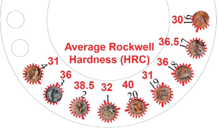
ness of Class 145 yield strength (145 ksi) and a minimum hardness of 34 Rockwell Hardness Scale C (HRC) and a maximum hardness of 38 HRC.”64 In spite of the fact that the Discoverer India bolts appeared to be within specification, BSEE reported “The QC-FIT found that bolt-hardness values above 34 HRC in a subsea environment remain an issue and should be the subject of additional testing.”65 In contrast the Seadrill WC studs, which had a Cameron specification of 31-35 HRC, and thus more reflective of BSEE’s concern, were found to have actual average hardness values that ranged from 30 to 41 HRC, with a majority below 35 HRC.66 It was further observed that “Some studs exhibited a variation in hardness across the section that ranged in some cases up to 8 HRC points…. This type of variation is indicative of a nonuniform heat treatment.”67
Regardless of the hardness, all failed Seadrill studs exhibited remarkably similar fracture features—that is, multiple IG initiation cracks around the perimeter of the root of the first loaded thread. These features were essentially identical to those observed in the failures from the Discoverer India, DAS, and PB10K rigs. Figure 2.4 (Figure 7 of the Stress Engineering Services report) has been annotated to include the average HRC stud hardness values for each bolt to illustrate the independence of hardness and fracture origin patterns and to highlight that bolts with hardness values significantly less than the industry-accepted value of 34 HRC also failed.
As with the case of the Discoverer India bolts, the report on the Seadrill WC rig indicated that the industry “RCA also determined that the subcontracted vendor’s non-compliance to the QA/QC processes led to deviations from the OEMs manufacturing specification.”68 And, again, the industry “RCA investigation attributed the failure to non-conformances to the manufacturer’s heat treatment material specifications, raw material specification, and quality control compliance impacting the fastener material properties.”69 This time BSEE appeared to be less convinced and determined the RCA to exhibit “inconclusiveness” and stated “BSEE recommends that a more detailed investigation be performed by an independent third-party testing laboratory on behalf of the operator to determine the specific damage mechanism.”70
___________________
64 BSEE, QC-FIT—Summary of Findings, 2014, p. 10.
65 BSEE, QC-FIT—Summary of Findings, 2014, p. 10.
66 Stress, Metallurgical Failure Analysis—Final Report, 2014, p. 18.
67 Stress, Metallurgical Failure Analysis—Final Report, 2014, p. 16.
68 BSEE, QC-FIT Evaluation of Fastener Failures—Addendum, QC-FIT Report #2016-04, Office of Offshore Regulatory Programs, Washington, D.C., February 2016, https://www.bsee.gov/sites/bsee_prod.opengov.ibmcloud.com/files/memos/public-engagement/qc-fit-bp-bolts-report-final.pdf, p. 5.
69 BSEE, QC-FIT Evaluation of Fastener Failures—Addendum, 2016, p. 4.
70 BSEE, QC-FIT Evaluation of Fastener Failures—Addendum, 2016, p. 5.
The industry RCA for the Seadrill WC failures specifically found “banding” in the stud microstructures that was attributed to using rolled bar from continuously cast ingots for the stud steel instead of the specified ingot cast material, “which can result in areas of localized high hardness and unexpected mechanical properties.” However, based on metallographic cross sections of multiple secondary cracks which emanated from primary cracks and short cracks at thread roots indicating crack nucleation there does not appear to be any evidence in the micrographs of the cracks that the banding played any role in crack nucleation or propagation. Specifically, the micrographs showed that the cracks that exhibited irregular crack paths characteristic of intergranular fracture by HE “independent of the hard/soft banded regions.” The report confirmed that the cracks progressed through or across the banded regions and showed no preference to propagate within these regions. In other words, the crack did not turn to follow the band along its long axis (and parallel to the major tensile stress axis) which is often seen in stress corrosion of alloys with susceptibility dependent on an undesirable metallurgical condition that creates an easily environmental fracture path. In such materials, even though the tensile stress is lower in a radial direction for a longitudinal crack, the metallurgical susceptibility becomes a dominant factor.
Prior to installation, the failed studs for both the Discoverer India and Seadrill WC rigs were coated with a protective zinc-chromate conversion coating.71,72,73 It was noted that this type of coating is designed to help prevent “corrosion during storage of the fasteners and to a certain degree acts as a corrosion protection layer, along with cathodic protection, in subsea application.” The potential contribution to the observed failures by the presence of the coating appears to have been overlooked as analyses of the Discoverer India failures by Stress Engineering Services indicated that “The zinc-chromate coating . . . appeared to have been consumed during service. Distinct white-colored deposits were observed throughout most of the bolt shank to varying extents. In every case, the fractures were coincident with areas where the coating had been compromised.”74 For the bolt failures from the Seadrill WC it was observed that “in every case, it was apparent that the coating was absent at the locations where fractures had occurred.” As discussed in the below, the committee believes a common mode of failure exhibited by all the Discoverer India bolts and Seadrill WC studs, of very different hardness, heat treating, and ingot creation is better explained by consideration of the various factors (e.g., coatings, impressed current systems, sacrificial anodes, etc.) which potentially contribute to the electrochemical nature of HE as discussed in the following paragraphs.
External cathodic protection can drive surface and circumferential cracks at a higher rate than deep radial cracks. Under cathodic polarization a negative electrode potential and subsequent high hydrogen overpotential is applied to exposed metallic surfaces which produces hydrogen and OH− in service. Any confined spaces such as crevices or cracks become increasingly alkaline relative to the bulk as a result of proton discharge and water reduction. In these situations, the crack tip potential is not as negative or in other words experiences somewhat more positive potentials due to ohmic voltage drop. Therefore, the overpotential for hydrogen production may be smaller at deeper radial crack tips than on the boldly exposed surfaces in the cathodic case, and the pH is higher. Taken together, hydrogen uptake may be slightly lower. However, visual inspection of the fracture surfaces of all the Discoverer India bolts and Seadrill studs revealed calcareous deposits in the cracks which serve as a positive indicator of cathodic polarization into growing cracks. When the overpotential for hydrogen production is greater on the bulk surfaces than at the crack tip, the diffusible hydrogen concentration may be larger near the most exposed surfaces and consequently the crack grows faster on the sample edges and around the circumference and penetrates radially towards the mid-thickness at a slower rate. That is, the circumferential edge of the first thread corresponds
___________________
71 BSEE, QC-FIT—Summary of Findings, 2014, p. 11.
72 Stress, Metallurgical Failure Analysis—Final Report, 2014, p. v.
73 BSEE, QC-FIT Evaluation of Fastener Failures—Addendum, 2016, p. 6.
74 Stress, Site Inspection, Metallurgical Examination, and Mechanical Damage Analysis, 2013, p. v.
to higher values of CH,diff, while the sample center in the radial direction would correspond to lower CH,diff values. Therefore, cathodic polarization may lead to greater hydrogen uptake at less occluded sites, and subsequent faster near surface cracking even though the stress intensity and hydrostatic stress may be lower at such locations.
However, the increased stress intensity at a deep radial crack tip and associated triaxial stress state there will eventually concentrate the hydrogen that is produced and absorbed there and at some point lead to a much higher local concentration at the surface than would be found throughout the material. Thus it is quite reasonable to expect the ring of intergranular fracture that was observed around the root of the thread, which in all cases was the primary location of the fracture. It is also reasonable to expect that some dominant radial cracks grow as indicated in Figure 2.4 growing radially from a limited number of circumferential cracks. The root of the thread would concentrate hydrogen in the material in that location, making it a preferred initiation site. In contrast, internal HE due to improper baking and resident internal hydrogen as a result of improper baking would not occur at the surface and spread circumferentially but occur at the peak stress under the notch. Moreover, calcareous deposits would not have been observed on cracks produced as a result of coatings and improper baking as this is an indicator of cathodic protection in seawater.
The immediate implication of this analysis is the Discoverer India bolts and Seadrill studs failure mechanism appears to have been misunderstood in the previous RCA efforts. The analysis suggest hydrogen-assisted SCC due to cathodic polarization occurred and the committee’s analysis does not support an argument towards banding microstructure, a specific hardness value nor zinc plating/and baking status as the cause of HE.
The question that must be answered is why these few cluster failures occurred, and no others. Most fasteners used undersea have an anodic coating, and if they were the root cause, failures would be more prevalent. Unfortunately, because there is no regular inspection of bolts removed from service that have not failed, or monitoring for incipient cracks of bolts in service that have not failed, we are left with only the evidence of these few cluster failures. Something about their specific application caused the service cathodic polarization to enable fasteners to experience high hydrogen overpotentials and high enough stress states to enable HAC (i.e., brittle failure modes) and ultimately resulted in HAC of the bolts, whereas in most flange connections this mechanism does not appear. This analysis makes it more imperative that BSEE call for greater industry research as cited elsewhere in this report.
A related unresolved issue is the observation of clusters of bolt failures all located in one flange by HAC given a possibly random set of bolts with respect to heat or lot origin and a range of hardness levels and processing conditions. It should be
mentioned that while the cluster of bolt failures all contained circumferential cracks that formed more or less over the same period of time, they may have followed some sequence where the rate of cracking varied over time for each fastener. Suppose that the first bolt to crack by HAC progressed to complete failure. This process would become evident in the fractography by ductile overload of a small remaining ligament of material near the center. When this is the case, it indicates that pre-load stresses in the bolt remained high enough during crack growth that the applied stress intensity reached fracture toughness in the material when the radial HE cracks were sufficiently long but before preload was bled off or lowered sufficiently to arrest the crack (crack growth relieves displacement controlled stresses).
The question then becomes how the failure of a single bolt changes the situation of remaining nearby bolts such that HE is more likely in these bolts. Cathodic protection and the environment would not change and neither did the anodic coatings. Metallurgy and hardness does change bolt to bolt, but not in a consistent pattern, and not in a pattern that seem to correlate with the failures. Preload does not transfer to adjacent bolts sufficient to cause ductile overload. Moreover, in the flanges associated with the failed bolts being evaluated, the combined effect of a correctly selected bolt preload of all the bolts should “insulate” the remaining bolts from the bulk of the operational load cycles with the failure of a single bolt, or perhaps two. However, with the loss of a few bolts, the operational bending loads on a bolted connection might now begin to exceed the effect of the remaining bolt preload, particularly for bolts immediately adjacent to those that have failed. While none of the failed bolts were reported to have exhibited any fatigue striations, the transfer of operational loading to the adjacent remaining bolts would lead to higher stresses and potentially accelerate the hydrogen cracking in those bolts in comparison to the other remaining bolts in the fixture further from the zone of failed bolts. As the following example illustrates, this mechanism would explain why all the failure WC studs were on one side of the connector and the absence of ductile overload or fatigue.
It should be noted from Figure 2.5 and literature that HAC is very sensitive to small changes in stress intensity, applied especially during what is known as stage I cracking. In this regime, crack velocity is affected significantly by small changes in stress intensity factor (SIF) and could essentially turn on or off, or significantly change the crack velocity. For instance, a change in bolt stress from just 60 percent of yield strength to 75 percent of yield strength for a fixed crack length can change the applied SIF by up to 5 MPa (m)1/2 which could enable the threshold stress intensity for HEC growth to be reached or exceeded and for the crack growth rate to increase by an order of magnitude or more. This situation would enable HEC in adjacent bolts but critically would never raise the applied SIF enough to induce ductile overload in a pristine hydrogen free fastener. This is consistent with the absence of ductile overload failure or fatigue on regions of the failed surface beneath intergranular cracks.
The committee is aware of other bolting failures in flanged connectors exhibiting the “cluster” phenomenon. But for various reasons, detailed information on these particular failures is not publicly available and cannot be explicitly identified in this report. The application conditions differed from those considered in this report—the flange had a large internal pressure load and few bolts, while the drilling riser system has no pressure and many bolts. Interestingly for these particular cases, the root cause of the bolt failures was determined to be HAC. Bolts failed on several flanges over a period of time.75 Some flanges, but not all, exhibited cluster failures. Loading of the flanges was not uniform along the structure, and loads on the flanges was
___________________
75 The committee was not able to gain any information on the exact timing of bolt failures.
believed to be relatively low. While the preload torque on bolts may not have been carefully documented or tracked, bolt preload was believed not to be a contributor to the bolt failures. If bolt preload tension was excessive, then bolts would have failed almost immediately. Rather, it appears that bolt failures occurred well after preloading during flange assembly. Bolt failure clusters are believed to have occurred in flanged connections which were loaded nonuniformly around the circumference of the flange. Some bolts may have had higher tensile loading than others, such as would be the case with bending loads. The sensitivity to the bolts to HAC resulted in initiation of brittle failure of a single bolt at a relatively low tension stress, and then the load transfer of service load to neighboring bolts could result in accelerated HAC failure of that neighboring bolt, and so on. It should be noted that the sensitivity of
the bolts to HAC may result in brittle fracture at low tensile loads, virtually always at the first exposed thread root. That is, the bolt stresses due to bending or tensile loads did not need to be large to cause HAC brittle fracture. The relatively low threshold stress intensity for HAC in these steels at finite diffusible hydrogen concentrations enable by cathodic protection makes this scenario possible. Gross overload leading to ductile fracture over the entire bolt cross sections was not observed.
Therefore, even though cluster failures are rare events, the potential consequence is very significant, and the root cause of this type of failure should be determined so that mitigating actions can be instituted.
Note that the committee choose to standardize the language in this report to HAC. However, this term is not meant to imply that existing cracking must be
present to be enhanced by the uptake of hydrogen. Other terms used by different authors to describe the phenomenon include HE, hydrogen environment-assisted cracking (HEAC), hydrogen-enhanced cracking (HEC), hydrogen-induced cracking (HIC), hydrogen-enhanced decohesion (HEDE), and hydrogen-enhanced local plasticity (HELP).
OPTIONS FOR IMPROVING THE SELECTION OF BOLTING MATERIAL PROPERTIES
Currently material specifications for steels and CRAs used in the manufacture of threaded connectors are primarily detailed in the relevant API specifications (e.g., 20E or 20F). The specified properties of interest are composition and mechanical properties (as per the relevant ASTM standard), processing history (to include melt practice and hot rolling details), casting history (continuous or ingot cast), inclusion content, grain size, degree of banding and microstructure. The only assessment of mechanical properties in the final heat-treated parts explicitly required in API Specs 20E and 20F is hardness. However, API Specs 20E and 20F incorporate by reference ASTM Specs A193, A194, A320, A453, and A540, which require additional mechanical testing. It is important that connector meet these normative ASTM specifications for the following reasons. Steels with the same hardness often exhibit microstructure-dependent yielding and strain hardening behaviors (as evidenced by the shapes of tensile stress-strain curves) that differ from traditional martensitic quenched and tempered steels. With the identification of alloys and microstructures which exhibit improved resistance to failure by HAC in comparison to currently available quenched and tempered martensitic steels or thermally processed (e.g., precipitation hardened) CRAs, more extensive quantification of mechanical properties via complete stress-strain curves and fracture toughness data will be required. One option will be to modify the standards to expand the specifications on mechanical properties, to include yield strengths, ductility, and ultimate tensile strengths. In addition, fracture testing by Charpy impact tests or fracture toughness tests with crack planes oriented to mirror observed fracture planes in threaded connectors also will provide essential information to further characterize and identify mechanical properties to guide material selection.
In addition to improved cleanliness brought about by modern steel making processes, multiple alloying and processing approaches are currently under investigation to produce steels with improved resistance to HAC. As summarized in Chapter 5, strategies employed in ongoing studies include alloy designs to resist hydrogen production and uptake, development of microstructures with constituents such as vanadium carbides which act as traps to sequester hydrogen away from fracture sites, and development of microstructures with inherently higher resistance to fracture. Approaches to the latter strategy include the use of interface
or grain boundary engineering, such as achieved by adding specific elements (e.g., rare earth elements) to control segregation of specific alloying elements (e.g., sulfur) often found on hydrogen-embrittled fracture surfaces. Assessments of potential new steels with improved resistance to HAC are also being aided by rapid advances in computational tools available to the alloy designer.
As the critical failures observed to date have been associated with environmentally assisted cracking (primarily identified as hydrogen embrittlement), incorporation of standard laboratory test methods to assess the susceptibility of candidate steels to hydrogen embrittlement and/or stress corrosion cracking should be required and the results would provide additional criteria for incorporation in standards for material selection and manufacture. It is recognized that several laboratory test methods currently exist76,77,78 to assess the relative susceptibility of HAC of different materials. However, these existing tests do not provide information on lifetimes under service loads/environments or establish windows of susceptibility using these methods alone. Thus one option will also be to establish a program to develop such a standard applicable to connector materials for offshore applications. It is also important to note that susceptibility is environment specific and standards developed for one set of environmental conditions—for example, sour service may not be directly applicable to seawater environments.79
Paralleling the option to consider new materials, coatings designed to mitigate the susceptibility of manufactured connectors to HAC, particularly when installed where active impressed current corrosion protection systems are operative, need to be assessed and potentially incorporated in standard modifications. Also, bolt designs as currently specified utilize standard well-accepted thread designs applicable to most all industries. To date, assessment of the selected thread design for offshore applications to ensure that the design exhibits the maximum resistance to environmentally assisted fracture has not been undertaken. Since the bolt design (including the tread geometry) is a “critical parameter,” systematic studies to assess effect of bolt design on HAC susceptibility would also be required for the various
___________________
76 ASTM International, Standard Test Method for Determining Threshold Stress Intensity Factor for Environment-Assisted Cracking of Metallic Materials, ASTM E1681-03, West Conshohocken, Pa., 2013.
77 ASTM International, Standard Test Method for Measurement of Hydrogen Embrittlement Threshold in Steel by the Incremental Step Loading Technique, ASTM F1624-12, West Conshohocken, Pa., 2012.
78 ASTM International, Standard Practice for Slow Strain Rate Testing to Evaluate the Susceptibility of Metallic Materials to Environmentally Assisted Cracking, ASTM G129-00, West Conshohocken, Pa., 2013.
79 NACE MR0175 gives requirements and recommendations for H2S containing environments and does not cover subsea applications. See NACE International, NACE Standard ANSI/NACE MR0175/ISO 15156, 2015, https://store.nace.org/ansi-nace-mr0175-iso-15156-2.
candidate materials identified in this option. For the additional property data, coatings, and bolt designs identified in this option, specific acceptable property levels would need to be identified to be incorporated in the standards. These property levels should include data in air and in an appropriate controlled environment to assess susceptibility to environmentally assisted cracking.
SUMMARY AND RECOMMENDATIONS
The design of a subsea drilling system and, its components, is a challenging engineering task requiring numerous technical disciplines at multiple companies. The bolted flange connectors within the subsea system are deceptively simple pieces of equipment. But because of the varied and dynamic forces acting on a bolted flange connector in subsea drilling applications, the design of a flange connector is complex. Of particular importance are the assumptions related to the operating environment, installation, operation, and maintenance practices that occur in shops and on rigs that affect the loads on the riser/BOP system. The challenge for the design engineer is to integrate the various levels of uncertainty to arrive at the appropriately conservative design for each mechanically fastened connection, and then for each individual fastener/bolt. Because bolts are subject to multiple time-dependent failure modes in addition to mechanical overloads, all potential failure modes must be identified and the risks must be mitigated during the design process.
Out of all this complexity, there are a few conclusions the committee has made: (1) The environment in which these subsea connectors operate (salinity, temperature, pressure, water chemistry, cathodic protection) is a design variable over which the design engineers have no control; (2) there are certainly urgent changes that should be made regarding the highly loaded bolts on subsea systems, however there are also innovation opportunities to reduce the high stress loading on these bolts and threads that should be undertaken; (3) the documented failures appear to be caused by environmentally assisted intergranular brittle failure of bolting in flanged connections, plus a few cases of what appeared to be ductile overload failures on the blind shear ram actuator housing; and (4) the most likely and immediate means of mitigating bolt failures lies in material science, material specifications, and quality control.
Finding: Oil and gas industry specifications and practice use torque as the value to be measured in tightening flange bolts. Torqueing, as currently specified in the oil and gas industry, is an inaccurate method of preloading flange bolts.
Finding: As operations have moved deeper offshore and bolts experience more demanding service, the use of torque as a bolt/stud/nut tightening criteria to establish
a connector tensile preload has outlived its usefulness. There is sufficient evidence that the practice of demanding increasingly accurate bolt torqueing equipment is non-optimal. Furthermore, it carries the risk of believing that the accuracy of torqueing reflects the accuracy of the desired design parameter-bolt preloading.
Finding: Current specifications for offshore fastener steels prohibit the use of continuous cast products, primarily because the existence of banding has been observed in steels which also failed in service by hydrogen embrittlement. However, as a result of recent advances in steel making casting technologies, significant advances in product quality have been realized.
Finding: A recent root cause analysis of bolt failures showed no direct relationship between crack initiation or growth by HAC and the presence of banding.80
Finding: Instances of “plastic deformation” and incipient HAC damage can go unnoticed by visual inspections of unbroken fasteners; such fasteners would be categorized as “failed” if properly identified and would not be re-used.
Finding: BSEE currently requires a visual inspection by ROV of a drilling riser and BOP every 3 days.81
Finding: BOPs are either sent to shore every 5 years for recertification or they are part of a Continuous Certification Program (CCP) in which the BOP Stack is inspected, maintained, tested, and certified by the OEM onboard the vessel/rig on a set frequency/schedule, thus eliminating the need to send it to shore every 5 years for recertification. Each OEM recommends an inspection program to the
___________________
80 Stress, Metallurgical Failure Analysis—Final Report, 2014.
81 30 CFR Chapter II, §250.739(c).
drilling contractor. All bolts are likely to be removed and visually inspected for flaws. During this inspection there is no requirement to perform NDT on bolts, studs, and nuts; nor is there a requirement to replace bolts, studs, and nuts that pass visual inspection.
Finding: There are several API documents that provide excellent techniques and guidance on various aspects of marine riser design, operations, inspection, and riser. These are:
- API Spec 16F, “Specification for Marine Drilling Riser Equipment”
- API RP 17G, “Recommended Practice for Completion/Worker Risers”
- API RP 16Q, “Recommended Practice for Design, Selection, Operation and Maintenance of Marine Drilling Riser Systems”
In particular, API RP 16Q, Chapter 6 (Riser Operations) and Chapter 7 ((Riser Integrity) provide excellent guidance relevant to bolt integrity.82
___________________
82 API, Design, Selection, Operation, and Maintenance of Marine Drilling Riser Systems, API RP 16Q, Washington, D.C., Chapters 6 and 7.
Finding: Hydrogen is produced during corrosion and its generation does not necessarily require the presence of cathodic protection (CP) currents. However, CP increases the rate of hydrogen production by increasing the reduction reaction on the metal surface and, therefore is a focus of this discussion. There is a range of complicating factors that affect the electrode potential on the metal surface and, thereby, affect the rate of hydrogen production.83
Finding: The U.S. Navy and the French Navy have begun to utilize “low voltage” aluminum anodes to decrease anodic voltage, thus reducing the risk of HAC of their high-strength alloys.
Recommendation 2.7: The oil and gas industry should establish a comprehensive methodology and or program to optimize the cathodic protection (CP) practice for critical assets containing fastener metallic materials. For current structures, CP monitoring and assessment practice should be instituted. As new structures are designed, the industry should establish CP design requirements optimized for materials in use, based on electrochemical fundamentals. This project should evaluate the use of “low voltage” aluminum anodes currently being used by the U.S. Navy and the French Navy to reduce the risk of hydrogen-assisted cracking of their high-strength alloys.
Finding: Hydrogen uptake and the diffusible hydrogen concentration follows a relationship where hydrogen concentration is proportional to the cathodic current density raised to some power—such as the one-half power.84 But hydrogen
___________________
83 Hydrogen is produced during corrosion and its generation does not necessarily require the presence of cathodic protection (CP) currents.
84 D. Li, R.P. Gangloff, and J.R. Scully, Hydrogen trap states in ultrahigh-strength AERMET 100 steel, Metallurgical and Materials Transactions A 35(3):849-864, 2004.
concentration can be affected by parameters that influence the atomic hydrogen concentration on the metal surface, such as sulfides. It is known that sulfides poison the combination reaction of atomic hydrogen to hydrogen gas, thereby increasing the atomic hydrogen concentration of the metal surface and increasing the hydrogen uptake into the metal.
Recommendation 2.8:
- The industry should review the usage of materials (e.g., lubricants containing sulfides) in contact with fasteners that are known to poison the chemical reaction of atomic hydrogen converting to molecular hydrogen (hydrogen gas), and identify substitute materials so that the concentration of atomic hydrogen at the metal surface is reduced.
- BSEE could consider immediately prohibiting the use of sulfide-containing lubricants until such a study indicated that they can be used without enabling hydrogen uptake.
Finding: Cluster failures involve the failure of multiple bolts in a single undersea flanged connector. Three rigs experienced cluster failure of H4 bolts, of common heritage, that secure the lower marine riser package (LMRP) from the blowout preventer (BOP) stack. Subsequently, nine fractured studs were found on another rig. These studs exhibited virtually the same failure mode and features observed in the three previous cluster failures while possessing NONE of the attributes that were supposedly the cause of the earlier failures; that is, had very different hardness, heat treating, and ingot creation.
Finding: Many of the critical failures observed to date have been associated with environmentally assisted cracking (primarily identified as hydrogen embrittlement). Standard laboratory test methods to assess the susceptibility of candidate
steels to hydrogen embrittlement and/or stress corrosion cracking are not adequate to determine the likelihood of HAC in the off shore environment.
Finding: There is not an accepted laboratory standard test method within the industry to assess the susceptibility HAC for bolting materials used in offshore applications.85,86
Recommendation 2.10: The oil and gas industry should establish through adequate research an accepted laboratory standard test method to assess the susceptibility to hydrogen assisted cracking of bolting materials and their coatings used in offshore applications.
Finding: Bolt designs, as currently specified in the oil and gas industry, utilize standard well-accepted thread designs. These thread designs can result in extremely high stress concentrations at the thread roots—especially on the first thread root. Other industries have utilized innovative designs to alleviate this problem.
Finding: Threads are generated by either machining or rolling. To date, assessment of the selected thread design and method of manufacture used for offshore applications to ensure that the design exhibits the maximum resistance to environmentally assisted fracture has not been undertaken.
Recommendation 2.11: The oil and gas industry should:
- Assess various thread designs and manufacturing methods for maximum resistance to environmentally assisted fracture.
- Conduct systematic studies to assess effect of bolt designs (including the tread geometry) on hydrogen assisted cracking susceptibility.
- Pursue research into thread designs which could reduce the stress concentration in bolt threads.
Recommendation 2.12: The oil and gas industry should review the standards relating to bolt tensioning, both in terms of loading as a percent of yield strength and in terms of preloading technique, to minimize the probability for under- or over-tensioning bolts operating in subsea environments.
__________________
___________________
85 General guidelines can be found in ISO 7539 Part 11 (Guidelines for testing the resistance of metals and alloys to hydrogen embrittlement and hydrogen-assisted cracking) at https://www.iso.org/standard/43440.html, accessed January 2, 2018.
86 For example, NACE MRO175 does not cover subsea applications. See NACE International, NACE Standard ANSI/NACE MR0175/ISO 15156, 2015, https://store.nace.org/ansi-nace-mr0175-iso-15156-2.


