
4
Accelerator Science, Technology, and Detectors Needed for a U.S.-Based Electron-Ion Collider
INTRODUCTION
In order to definitively answer the compelling scientific questions elaborated in Chapter 2, including the origin of the mass and spin of the nucleon and probing the role of gluons in nuclei, a new accelerator facility is required, an electron-ion collider (EIC) with unprecedented capabilities beyond previous electron scattering programs. An EIC must enable the following:
- Extensive center-of-mass energy range, from ~20-~100 GeV, upgradable to ~140 GeV, to map the transition in nuclear properties from a dilute gas of quarks and gluons to saturated gluonic matter.
- Ion beams from deuterons to the heaviest stable nuclei.
- Luminosity on the order of 100 to 1,000 times higher than the earlier electron-proton collider Hadron-Electron Ring Accelerator (HERA) at Deutsches Elektronen-Synchrotron (DESY), to allow unprecedented three-dimensional (3D) imaging of the gluon and sea quark distributions in nucleons and nuclei.
- Spin-polarized (~70 percent at a minimum) electron and proton/light-ion beams to explore the correlations of gluon and sea quark distributions with the overall nucleon spin. Polarized colliding beams have been achieved before only at HERA (with electrons and positrons only) and Relativistic Heavy Ion Collider (RHIC; with protons only).
- One or more interaction regions, which integrate the detectors into the collider and preserve the extensive kinematic coverage for measurements.
In addition, modern particle detector systems will be essential for an EIC. Generic research and design efforts are under way on novel ideas, including compact calorimetry and various tracking and particle identification detectors.
The EIC accelerator requirements are by and large beyond the limits of current technology and their realization requires significant research and development (R&D). Indeed, an important element of the scientific justification for a U.S. electron-ion facility is that it drives advances in accelerator science and technology, which in turn will benefit other fields of accelerator-based science and society.
The three primary areas that require significant accelerator science and technology R&D are energy, luminosity, and polarization. The extensive energy variability and elaborate interaction region of an EIC require advanced superconducting magnet designs beyond state of the art. To attain the highest luminosities demanded by the science, cooling of the hadron beam is essential. Novel beam cooling techniques are under development. Energy recovery linacs (ERLs), a special type of recirculating linac, presently offer the only credible concept for electron cooling of high-energy, colliding beams. To optimize the overlap of the colliding beams at the interaction point, specialized superconducting radio-frequency (SRF) cavities rotate the beams as they collide. Polarized beams require polarized particle sources beyond the state of the art, special magnets, and a further level of mastery of beam physics to preserve the polarization through the acceleration process to the collisions.
Two conceptual designs for an EIC facility have evolved in the United States, each of which proposes using infrastructure already available to the U.S. nuclear science community. One, eRHIC, is based on the RHIC ion complex at Brookhaven National Laboratory (BNL); and the other, Jefferson Laboratory Electron Ion Collider (JLEIC), uses the Continuous Electron Beam Accelerator Facility (CEBAF) at the Thomas Jefferson National Accelerator Facility (JLab) as a full-energy electron injector. In order to motivate the accelerator science, technology, and detector R&D required for the realization of a U.S.-based EIC, the sections below provide a description of the two conceptual designs of an EIC.
DESCRIPTION OF BNL AND JLAB ACCELERATOR CONCEPTS
The eRHIC Conceptual Design
The proposal for an EIC to be built at BNL already has a long history during which several variants of the design have been explored in depth. All have been
based on reutilization of the existing RHIC facility as the hadron accelerator, thereby leveraging a substantial past investment. RHIC is one of only two hadron colliders in the world and is now the only collider of any kind operating in the United States. Since its start-up in 1999, it has proved to be a remarkably flexible collider of heavy and light ions as well as polarized protons (discussed further in Chapter 5).
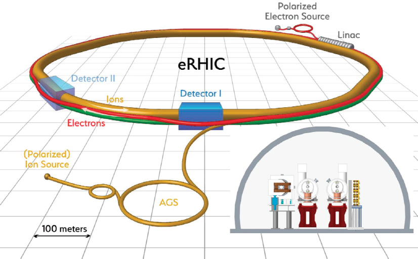
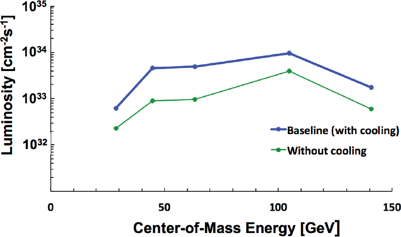
The present eRHIC proposal would add a high-intensity 5-18 GeV electron storage ring in the RHIC tunnel to collide electrons with the protons (up to 275 GeV—compared with the 255 GeV currently used in experiment) and ions (up to 100 GeV per nucleon) in one of the two existing RHIC rings, as shown in Figure 4.1. This design considerably reduces the technical risk that was associated with the previous linac-ring concept (see Box 4.1). The luminosity achievable in this way is sufficient to pursue an important set of EIC physics goals (see Figure 4.2). However, the full luminosity goals of eRHIC require the implementation of a radically new hadron cooling technology, discussed further below.
Energy
Electrons and ions or protons are collided at the effective electron-nucleon center-of-mass energy ![]() , where Ee is the electron energy and EN is the energy of a proton beam or the energy per nucleon of an ion beam. With electron energies of 5-18 GeV, protons of 41-275 GeV, and ions of up to 100 GeV per nucleon, a wide range of
, where Ee is the electron energy and EN is the energy of a proton beam or the energy per nucleon of an ion beam. With electron energies of 5-18 GeV, protons of 41-275 GeV, and ions of up to 100 GeV per nucleon, a wide range of ![]() , from 30-140 GeV (for ep) and up to 100 GeV (eA) is accessible. The Electron Beam Ionization Source (EBIS) and injector complex of RHIC can supply a broad range of heavy and light species.
, from 30-140 GeV (for ep) and up to 100 GeV (eA) is accessible. The Electron Beam Ionization Source (EBIS) and injector complex of RHIC can supply a broad range of heavy and light species.
Luminosity
High luminosity is achieved by colliding many high-intensity bunches of particles. It is further increased by reducing the beam sizes as much as possible at the collision point by focusing the beams very strongly. This is limited by the “emittance,” or intrinsic phase space volume (in real space and momentum space) occupied by the particle distribution. The electron beam emittance is essentially determined by synchrotron radiation in the bending and focusing magnets of the
TABLE 4.1 Main Parameters of eRHIC for Collisions of Protons, at Their Maximum Energy of 275 GeV, with 10 GeV Electrons
| Parameter | Units | No Hadron Cooling | Strong Hadron Cooling | ||
|---|---|---|---|---|---|
| Particle | Protons | Electrons | Protons | Electrons | |
| Center-of-mass energy | Gev | 105 | 105 | ||
| Beam energy | Gev | 275 | 10 | 275 | 10 |
| Collision frequency | MHz | 56.3 | 112.6 | ||
| Particles/bunch | 1010 | 10.5 | 30 | 6 | 15.1 |
| Beam current | A | 0.87 | 2.5 | 0.99 | 2.5 |
| Bunch length, RMS | cm | 7 | 1.9 | 5 | 1.9 |
| Emittance norm (x,y) | µm | 4.1/2.50 | 391/87.1 | 2.7/0.36 | 391/19.0 |
| Luminosity / IP | 1034 cm–2s–1 | 0.44 | 1.02 | ||
NOTE: Two sets of parameters are given, indicating the maximum luminosity performance achievable with and without strong hadron beam cooling. RMS, root mean square.
SOURCE: F. Willeke, “eRHIC Overview,” Design Choice Validation Review, April 5-6, 2017.
electron ring. The hadron beam emittance is determined in the injection system but can be influenced by a cooling system.
The electron ring is designed to store beam currents up to 2.5A in 1,320 bunches per ring, a performance similar to B-factories. With the hadron emittance and density provided by the injectors, the eRHIC design should achieve a peak e-p luminosity of 4.4 × 1033 cm−2s−1. Strong hadron beam cooling would boost this by a factor of approximately 2.5 to achieve the peak luminosity of 1.02 × 1034 cm−2s−1 for which the eRHIC facility is designed. Beam parameters for these two conditions are given in Table 4.1.
Besides the collisions with other ion species, the collider is flexible enough to provide a range of different operational conditions. For example, the study of Deeply Virtual Compton Scattering (Chapter 2) requires limiting the proton momentum and proton beam divergence, or angular spread, to less than 1 percent of the beam momentum. Because strongly focused beams have high divergence, this leads to alternative “high acceptance” parameter sets with reduced luminosity that would allow the detection of protons with low transverse momenta.1,2
___________________
1 C. Montag et al., 2017, Overview of the eRHIC ring-ring design, in Proceedings of IPAC 2017, Copenhagen, Denmark, WEPIK049, http://accelconf.web.cern.ch/AccelConf/ipac2017/papers/wepik049.pdf.
2 R.B. Palmer and C. Montag, 2017, Parameters for eRHIC, in Proceedings of IPAC 2017, Copenhagen, Denmark WEPIK049, http://accelconf.web.cern.ch/AccelConf/ipac2017/papers/wepik050.pdf.
Electron Ring
The new electron ring to be installed in the RHIC tunnel would be composed of focusing and defocusing quadrupole magnet cells, except in the two experimental straight sections. While their focusing structure is quite conventional, their bending magnets are not; these “superbends” are designed as a sequence of three magnets with a strong central pole. While each magnet bends in the same direction at high energy, the central pole is reversed at lower energies, introducing a scalloped form of the orbit. The purpose of this is to increase the energy lost by synchrotron radiation to a value defined by a trade-off between the operational cost and the beneficial effect of increasing the radiative damping of the particle oscillations. The radiation damping makes electron bunches more immune to disruption by the beam-beam interaction when they collide with the hadrons. This boosts the luminosity that can be achieved at lower energies.
Hadron Ring
The hadron ring consists essentially of the main superconducting magnets of one of the two existing RHIC rings. However, it must be modified to cope with a much larger number of particle bunches (a factor 10 more than the present 120 in RHIC).
New injection kickers with a 30 ns rise time and a new injection transfer line arrangement will be needed. The high beam current would induce an unacceptable heat load on the stainless steel beam pipe. To counter this, BNL is developing technologies for in situ coating the pipe with copper, and then amorphous carbon, to reduce the secondary electron yield.
Interaction Region
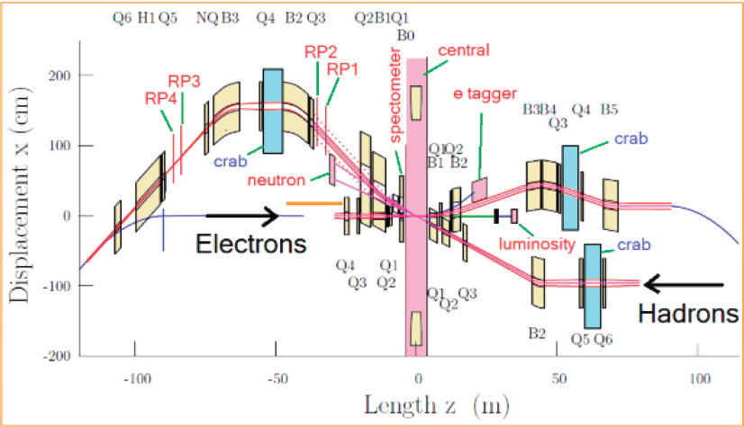
The design of an interaction region that must focus, collide, and separate beams of quite different momenta is necessarily complex. Figure 4.3 gives an impression of the solution adopted for eRHIC. The bunches of the two beams are collided at an angle of 22 mrad (about 1.25 degrees), which would result in reduced overlap and luminosity. This is avoided by rotating both beams to achieve full overlap using “crab cavities” in the interaction region. These are a special design of SRF cavities, which deflect, rather than accelerate, the beam.
The cold masses of the focusing quadrupoles for the two beams are arranged in an interleaved pattern. Special designs are required to shield the electron beam from the stray field of the hadron quadrupoles. There are numerous other features and constraints on the design of the interaction region that are not discussed here.
Radio Frequency Systems
At a maximum energy of 18 GeV, the eRHIC electron ring would require 41 MV of peak circumferential voltage to compensate synchrotron radiation losses and ensure adequate beam lifetime. Considerations of cost, space, and mitigation of the unwanted higher order mode power have led to the selection of a 563 MHz 2-cell cavity for the electron ring radio frequency (RF) system. Thirty-six cells are required to compensate for the losses at peak energy. The overall power provided to the electron beams is limited administratively to 10 MW.
In the hadron ring, the present 197 MHz RF system will be replaced by a higher frequency system to shorten the hadron bunch length to a scale comparable to the eRHIC vertical beam size at the interaction point (IP), thus avoiding luminosity reduction caused by the so-called “hourglass effect.” In the inner part of the interaction region, the vertical beam size grows parabolically with distance away from the interaction point. In order to keep both colliding beams within the tightly focused area near the IP, thus maximizing the contribution to luminosity, the hadron bunch length has to be as short as possible. For this purpose 563 MHz cavities, the same
frequency as the electron storage ring cavities, are being considered. The 336 MHz crab cavities should provide about 10 MV to the hadron beam.
Polarization
RHIC has already operated with great success as a polarized proton collider (see Chapter 5). The eRHIC physics program further requires polarized electrons with the possibility of opposite polarization directions from bunch to bunch. This can be achieved only with a full-energy polarized electron injector. Once the electron bunches are stored, their polarization evolves due to a spin-flip component of synchrotron radiation toward an equilibrium state direction that is opposite to the main bending field. This radiative self-polarization mechanism3 deteriorates the polarization of those electron bunches that are initially oriented along the bending field on a time scale ranging from a few tens of minutes to a few hours, depending on the beam energy and magnetic field. Additionally, spin diffusion due to synchrotron radiation may enhance the polarization decay, especially near energies corresponding to specific resonance conditions between the spin precession and orbital oscillations. In order to maintain an adequate average polarization, the bunches must be replaced with fresh ones at a maximum rate of one bunch per second.
Electron Injector
A polarized source and recirculating electron linac could meet the eRHIC electron injector requirements. However, a more economical solution is under study. A rapid-cycling synchrotron could be installed in the RHIC tunnel. A recently invented special optics configuration could be used to preserve the polarization through the acceleration process.
The JLEIC Conceptual Design
JLEIC is JLab’s proposal for an EIC. It is the culmination of long and in-depth study of collider designs that would take full advantage of the existing electron accelerator facility—in particular, its recent upgrade to 12 GeV. It is a ring-ring collider designed to deliver high luminosity up to 1034 cm–2s–1 per interaction
___________________
3 Radiative self-polarization, often associated with the names of Sokolov and Ternov, is a mechanism by which the polarization of a beam builds up through a subtle interplay of orbital motion and spin precessions. The physics is lucidly discussed in J.D. Jackson, 1976, On understanding spin-flip synchrotron radiation and the transverse polarization of electrons in storage rings, Rev. Mod. Phys. 48:417.
region over a broad center-of-mass energy range, high polarization in excess of 80 percent for both electron and light ion beams, and full detection acceptance and forward tagging.
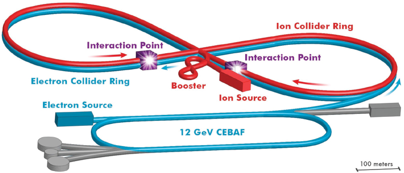
The JLEIC baseline concept is illustrated in Figure 4.4. The central part of the facility is a set of two figure-8 shape collider rings, one for electrons and one for ions. The CEBAF SRF linac is a full-energy injector to the electron collider ring, which will store an electron beam of 3 to 10 GeV energy. The maximum stored electron current is 3 A. The new ion complex includes an ion injector (sources, a SRF linac, and a figure-8 booster) and an ion collider ring. The stored ion beam current is up to 0.75 A. The two collider rings are stacked vertically and housed in the same underground tunnel. They are about 2.2 km in circumference and fit in the JLab site.
Energy
The electron-nucleon center-of-mass energy, ![]() , of JLEIC is 15 to 65 GeV achieved by the following energy ranges of the colliding beams: from 3 to 10 GeV for electrons, from 20 to 100 GeV for protons, and up to 40 GeV per nucleon for ions. A center-of-mass energy of 100 GeV can be achieved by increasing the proton energy to 200 GeV (ion ring arc dipole field from 3 T to 6 T) and by taking full advantage of the 12 GeV CEBAF energy.
, of JLEIC is 15 to 65 GeV achieved by the following energy ranges of the colliding beams: from 3 to 10 GeV for electrons, from 20 to 100 GeV for protons, and up to 40 GeV per nucleon for ions. A center-of-mass energy of 100 GeV can be achieved by increasing the proton energy to 200 GeV (ion ring arc dipole field from 3 T to 6 T) and by taking full advantage of the 12 GeV CEBAF energy.
Luminosity Concept
While the key to high luminosity in JLEIC is high bunch repetition rate of the colliding beams, the JLEIC high-luminosity strategy is based on multiple factors, as follows:
- Ultra-high collision frequency;
- Very short bunches and very small transverse emittance for both electron and ion beams;
- Multistage electron cooling to achieve appropriate ion emittances;
- Very strong final focusing (very small beam size) at the interaction point;
- Large attainable beam-beam tune shift; and
- Large (50 mrad) crossing angle and crab crossing of colliding beams.
Specifically, both the electron and ion beams have very short bunch lengths and small transverse emittances to enable strong final focusing to reduce the beam spot sizes of a few micrometers (a micrometer is equal to 1 × 10⁻⁶ m) at the collision point. This configuration, combined with a high bunch repetition rate, boosts the collider luminosity. A high bunch repetition rate enables a modest bunch charge to be used, allowing for relatively weak collective and intra-beam4 scattering effects, particularly in the ion beams, while maintaining high beam current to provide high luminosity. This luminosity concept has been validated at today’s lepton colliders such as the B-factories, which achieve luminosities above 1034 cm–2s–1.
An essential element of the JLEIC luminosity concept is electron cooling for reducing the ion beam emittance. To achieve the required high efficiency, JLEIC adopts a multi-phased cooling scheme, which utilizes two electron coolers, a magnetized DC cooler in the booster synchrotron, and a magnetized bunched-beam cooler based on an ERL for the collider ring.
Polarization
CEBAF is a fully polarized electron injector, and the polarization in the electron ring can be preserved by appropriate spin matching. A set of spin rotators with energy-independent geometry aligns the electron spins in the required longitudinal direction at the collision points and in the vertical direction in the arcs. The spin dynamics is entirely symmetric for oppositely polarized bunches. For energies above 7 GeV, the depolarization time of the JLEIC electron collider ring is very short, in the range of approximately 2 hours to 20 minutes (at 10 GeV). In order to
___________________
4 Intra-beam scattering (IBS) refers to the effect of multiple small deflections of particles encountering each other within the beams, leading to a growth of the beam size and reduction of luminosity.
maintain high polarization (above 80 percent), the present JLEIC baseline utilizes a scheme of continuous injection of very low current (a few nA) electron beam with high polarization from the CEBAF linac to replace the electron bunches with the most degraded polarization already in the collider ring. This scheme is called “top-off” injection.
Achieving high polarization in the ion ring requires state-of-the-art polarized ion sources. In addition, the polarization must be preserved during acceleration. JLEIC uses a figure-8 layout for the booster and collider rings, in which spin precessions in the left and right half-rings are canceled, resulting in zero spin precession, effectively eliminating crossing of spin resonances during energy ramping. Moreover, only weak magnetic fields are necessary for spin control and manipulation, making possible colliding polarized deuterons.
Magnets and RF System
The bunch repetition rate of the JLEIC stored beams is 476 MHz, driven by the plan to reuse PEP-II warm RF cavities and RF stations for the electron collider ring. A conceptual scheme has been developed for injecting the electron bunches from the CEBAF SRF linac (which has a frequency of 1.497 GHz) into the collider ring. All new RF cavities and RF stations required for the ion collider ring will have a frequency of 952 MHz, thereby enabling cost effective future improvements in luminosity and energy. The designs of the booster and collider rings are based on super-ferric magnet technology, which offers substantial savings in capital and operating costs, but requires R&D, as elaborated below.
Interaction Region
The design of the JLEIC interaction region is aimed at achieving high luminosity in an integrated full-acceptance detector. The current JLEIC detector design requires a magnet-free space of 7 m for the ion beam on the downstream side, and after optimization, only 3.6 m on the upstream side. For the electron beam, the first final focusing elements are permanent magnets which, thanks to their small sizes, can be placed inside the main detector and very close to the interaction point. In the JLEIC design the beams collide at an angle to avoid all parasitic collisions. A local compensation scheme based on SRF crab cavities is utilized to restore head-on collisions thus recovering the loss of luminosity caused by the crossing angle. A relatively large crossing angle also enhances the detection of reacting particles. The interaction region (IR) design uses a combined local and global compensation scheme to control the chromatic aberrations.
TABLE 4.2 Main Parameters of the Jefferson Laboratory Electron-Ion Collider for Collisions of Protons with Electrons for a Full Acceptance Detector
| Parameter | Units | Low Center-of-Mass Energy | Medium Center-of-Mass Energy | High Center-of-Mass Energy | |||
|---|---|---|---|---|---|---|---|
| Particle | Protons | Electrons | Protons | Electrons | Protons | Electrons | |
| Center-of-mass energy | Gev | 21.9 | 44.7 | 63.3 | |||
| Beam energy | Gev | 40 | 3 | 100 | 5 | 100 | 10 |
| Collision frequency | MHz | 476 | 476 | 476/4=119 | |||
| Particles/bunch | 1010 | 0.98 | 3.7 | 0.98 | 3.7 | 3.9 | 3.9 |
| Beam current | A | 0.75 | 2.8 | 0.75 | 2.8 | 0.75 | 0.71 |
| Bunch length, RMS | cm | 3 | 1 | 1 | 1 | 2.2 | 1 |
| Emittance norm (x,y) | µm | 0.3/0.3 | 24/24 | 0.5/0.1 | 54/10.8 | 0.9/0.18 | 432/86 |
| Luminosity / IP | 1034 cm–2s–1 | 0.25 | 2.14 | 0.59 | |||
NOTE: Three sets of parameters are given at different center-of-mass energies. RMS, root mean square.
SOURCE: Yuhong Zhang, talk at EIC Collaboration meeting, October 2017, Brookhaven National Lab, Upton, N.Y., https://indico.bnl.gov/getFile.py/access?contribId=2&sessionId=0&resId=0&materialId=slides&confId=3492, accessed August 13, 2018.
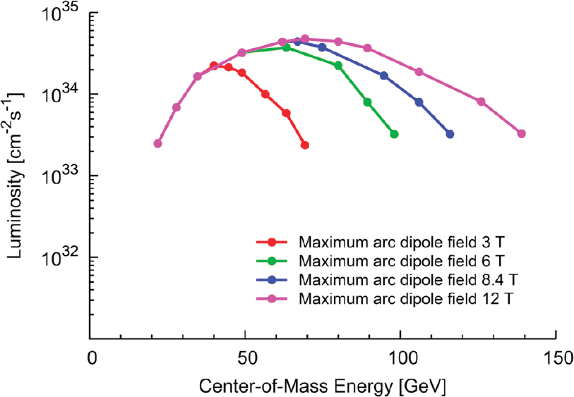
JLEIC Parameters and Performance
The JLEIC main design parameters are summarized in Table 4.2, and the luminosity performance for e-p collision is shown in Figure 4.5. The figure also shows the potential of a future energy upgrade by replacing the 3 T super-ferric magnets with higher field superconducting magnets. Similar high luminosities also can be achieved for various eA collisions. Without cooling during collisions, the expected luminosity is lowered to about 2 to 3 × 1033 cm–2s–1, assuming that one can refill the ion collider every 3 hours to counteract intra-beam scattering (IBS) emittance growth.
ENABLING ACCELERATOR TECHNOLOGIES
To reach the performance goals of the proposed EIC conceptual designs, a number of accelerator advances are required. Several of these advances are common to all EIC designs and include the following: advanced magnet designs, strong hadron beam cooling, high-current (multiturn) ERL technology, crab cavity operation with hadron beams, the generation of polarized 3He beams, and development and benchmarking of simulation tools. The successful implementation of an EIC requires the successful validation of these key concepts through high-fidelity simulations and demonstration experiments. The following sections review these enabling technologies, the present state of the art, and required research and development to meet EIC facility specifications and realize EIC science.
Magnet Technologies
Several magnet designs of both the JLEIC and eRHIC concepts are beyond state of the art. Magnet technology R&D is required for the JLEIC ion ring magnets, the interaction region magnets for both designs, and the solenoids for the electron cooler and spin control.
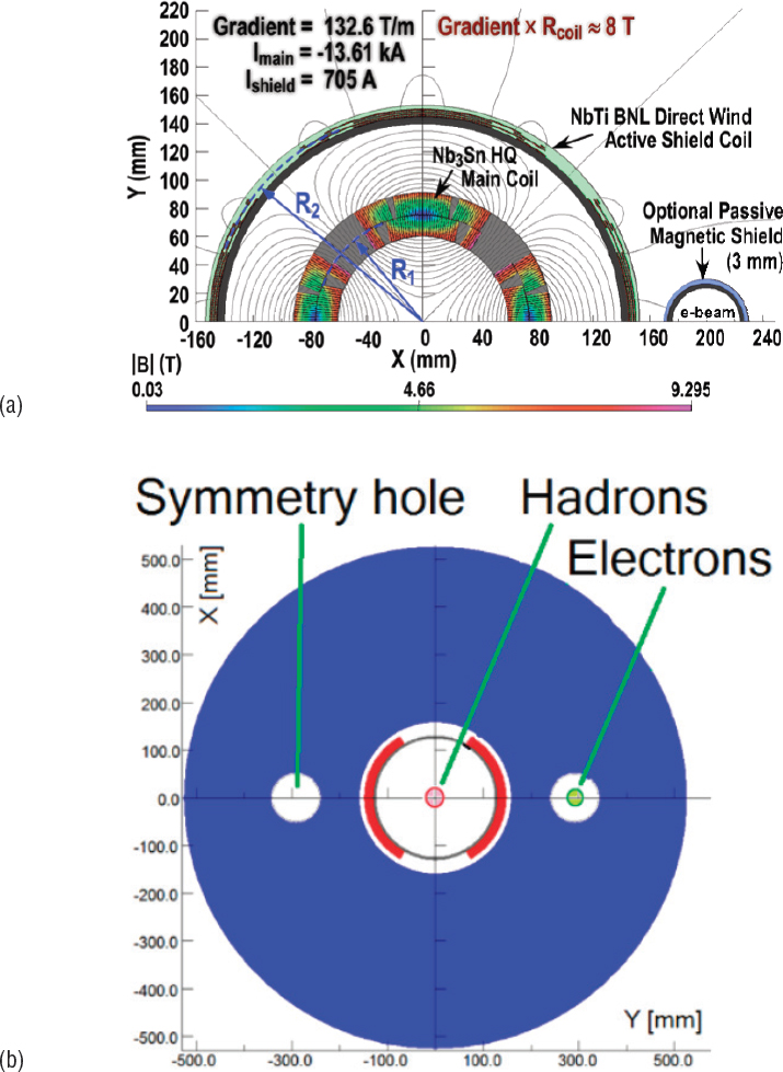
In the case of the eRHIC design, the crossing angle of 22 mrad calls for combination of active and passive shielding to provide a field-free pass of the electron beam inside the IR quadrupole (see Figure 4.6a). For other IR magnets, the penetration of the electron beam through the yoke of the ion magnets is arranged as shown in Figure 4.6b. Therefore, the eRHIC magnet R&D focuses on further developing active shielding technology, originally explored for the International Linear Collider (ILC) IR magnets, with a goal of fabricating and testing a short active-shielded magnet prototype.
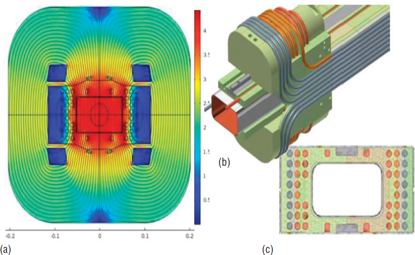
In the case of JLEIC, fast-ramped 3 T super-ferric dipoles for the ion booster and collider rings represent both a cost-effective option and an advance in conductor technology. However, the technology is not well established or fully validated. The cable-in-conduit conductor technology (see Figure 4.7) developed by Texas A&M University’s Accelerator Research Laboratory and utilized in these super-ferric magnets, can withstand the high ramp rate required in the ion booster magnets. The JLEIC magnet R&D program focuses on validating the super-ferric technology for 3 T and 6 T magnets, and on the development of IR magnets (final focus quadrupoles and dipoles), which are compact, high field, and robust in a high-radiation environment and have large aperture.
A key technical area common to all EIC concepts is the validation of magnet designs associated with high-acceptance interaction points by prototyping. In order to attain the high luminosity required, the final focus quadrupole magnets must be in close proximity to the interaction point. Large magnet apertures are required to
maximize acceptance by the detectors. The first spectrometer dipoles must also have large apertures for detector acceptance and accommodating the close proximity of the adjacent electron beam pipe.
Strong Hadron Beam Cooling
Cooling of hadron beams is essential to achieving the highest luminosities demanded by the EIC science. Both the JLEIC and eRHIC concepts have adopted novel beam cooling techniques that require significant R&D. JLEIC employs a multiphased cooling scheme, while eRHIC considers various new approaches using electron beams. One of them, coherent electron cooling (CeC) is being subjected to a proof-of-principle test at RHIC.
JLEIC Multiphase Electron Cooling
As a critical part of the luminosity concept, JLEIC employs conventional electron cooling technology for reducing the ion beam emittance. It also adopts a
TABLE 4.3 Jefferson Laboratory Electron-Ion Collider Multiphase Electron Cooling
| Phase | Functions | Proton Kinetic Energy (GeV/u) | Electron Kinetic Energy (MeV) | Cooler Type | |
|---|---|---|---|---|---|
| Booster | 1 | Assisting accumulation of ions | 0.11 ~ 0.19 | 0.062 ~ 0.1 | DC |
| 2 | Emittance reduction | 2 | 1.09 | ||
| Collider ring | 3 | Suppressing IBS and maintaining emittance during stacking of beams | 7.9 | 4.3 | Bunched beam (ERL) |
| 4 | Suppressing IBS and maintaining emittance during collision | 100 | 55 |
NOTE: ELC, Energy recovery linac; IBS, intra-beam scattering.
SOURCE: Yuhong Zhang, talk at EIC Collaboration meeting, October 2017, Brookhaven National Laboratory, Upton, N.Y., https://indico.bnl.gov/getFile.py/access?contribId=2&sessionId=0&resId=0&materialId=slides&confId=3492, accessed August 13, 2018.
multiphased cooling scheme, as summarized in Table 4.3, to achieve the required high efficiency. The scheme utilizes two electron coolers, a magnetized DC cooler in the booster synchrotron, and a magnetized bunched-beam cooler based on an ERL for the collider ring, with its schematic design shown in Figure 4.8. The DC cooler is state-of-the art, off-the-shelf technology. R&D is necessary in the area of magnetized bunched beam cooling.
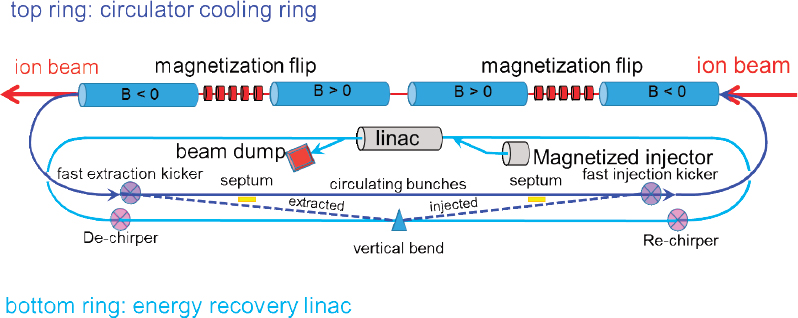
A single-turn ERL cooler enables luminosity of approximately 3 to 4 × 1033 cm–2s–1. The efficiency of electron cooling can be significantly enhanced by circulating the cooling beam a few times hence boosting the current, and enabling luminosity in excess of 1034 cm–2s–1. Circulating the cooling beam also relaxes the electron source requirements. One challenge of a multipass cooling scheme is the development of a fast kicker to switch the cooling bunches in and out of circulation. R&D on a fast kicker prototype is ongoing at JLab and is very promising. Further R&D requirements include ERL design for single-turn and multiturn operation; development of a high-current, magnetized source for the electron cooler; and electron cooling simulations.
Coherent Electron Cooling, as Applied to eRHIC
One of the most remarkable innovations at RHIC was the implementation of bunched-beam stochastic cooling of the heavy-ion beams at full energy in collision. Stochastic cooling, in which an RF “pick-up” measures fluctuations in the particle distribution that are later corrected in a subsequent kicker stage, has been effective in reversing the beam size increase due to intra-beam scattering and has resulted in an increase in luminosity and considerable increase in the physics reach of the RHIC collider. However, the full performance of eRHIC, with much higher peak currents than those of RHIC, requires improved cooling rates, therefore much higher bandwidth systems, beyond the capabilities of any established cooling technology. CeC, a promising new approach that uses an electron beam as both the pick-up and kicker, has been proposed.5 Various high-bandwidth amplifiers have been proposed, including a free-electron laser6 (FEL) and microbunching instability7 (MBI). The FEL has received the most attention to date.
The principle of CeC is illustrated in Figure 4.9. In the first section, the Coulomb field of the ion modulates the electron energies. Electrons and ions take separate paths in the second section. Electrons go through an amplifier section, FEL or MBI, which converts the energy modulation to a density spike at the ion’s former location in the electron beam. The ions go through a dispersive section, where an ion with lower than average energy falls behind the density spike it created, and an ion with above average energy slips ahead of its density spike. When the ion and electron beams are brought together again in the last section, a lower energy ion will have fallen behind and the Coulomb field of the density spike provides an energy boost; conversely, a higher energy ion will have slipped ahead and the col-
___________________
5 V. Litvinenko and Y. Derbenev, 2009, Coherent electron cooling, Phys. Rev. Lett. 102:114801.
6 D. Ratner, 2013, Microbunched electron cooling for high-energy hadron beams, Phys. Rev. Lett. 111:084802.
7 Ibid.
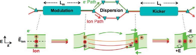
lective electron field pulls the ion backward, reducing its energy. The net effect is to push all ions toward the average energy—that is, cooling. Theory suggests that cooling times of seconds to minutes are achievable.
While of great interest and promise, this technique still requires significant R&D and experimental validation. A proof of principle experiment is currently under way at RHIC.
Energy Recovery Linacs
ERLs, a high-performance and high-efficiency type of recirculating linac, presently offer the only credible concept for electron cooling of high-energy colliding beams. The idea of energy recovery in a recirculating RF linac is based on the fact that the RF fields, by proper choice of the time of arrival of the electron bunches in the linac, may be used to both accelerate and decelerate the same beam. In an ERL, the electron beam is generated in a high-brightness electron source and injected into the linac, timed to be accelerated on the first pass through the linac. It is then transported through a magnetic arc to its point of use (e.g., the interaction region with protons or ions, in the case of an electron cooling device or an EIC) and then transported back to the entrance of the linac. If the recirculation path is chosen to be precisely an integer plus ½ RF wavelengths, then, on the second pass through the linac, the beam will be decelerated by the same RF field that accelerated it on the first pass. For the RF cavities within the recirculation loop, energy is directly transferred, via the RF field, from the decelerating beam to the accelerating beam; therefore, the RF power systems do not need to provide the energy to accelerate the first-pass beam. Indeed, the RF power draw becomes almost completely independent of beam current. ERLs can, in principle, accelerate very high currents with only modest amounts of RF power. This feature makes ERLs an attractive
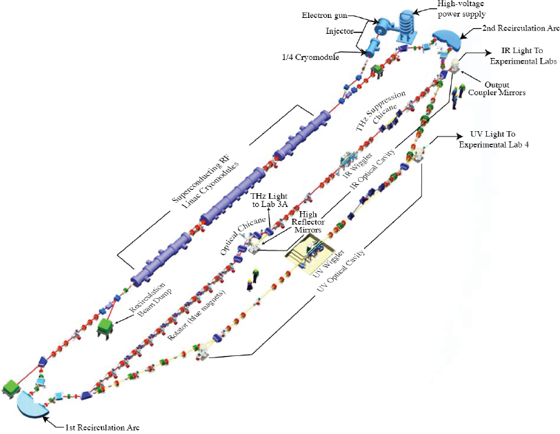
concept for a variety of applications, including higher-power FELs, synchrotron radiation sources, electron cooling devices, and high-luminosity EICs. The majority of operating and proposed ERLs are based on SRF linacs, due to their greater efficiency of energy recovery. Figure 4.10 illustrates the JLab IR and UV ERL-FEL.
To date, several ERLs have operated successfully and established the fundamental principles of energy recovery. The ERLs required for electron cooling are at scales much larger than supported by present-day experience, so a number of accelerator physics and technology challenges still need to be overcome with focused R&D and great attention to detailed simulations. The challenges center around the following three major areas:
- Achieving high electron source brightness;
- Maintaining high beam brightness through the accelerator transport (beam dynamics of an unprecedented number of spatially superposed bunches in the SRF linacs; very precise phase and amplitude control); and
- Dealing with unprecedented beam currents in SRF linacs (halo mitigation, beam breakup instabilities, higher order mode dissipation).
Many of these R&D issues are being investigated vigorously in dedicated test facilities under construction and commissioning in laboratories around the world. Specifically, the 4-pass Fixed-Field Alternating Gradient R&D loop for eRHIC (see
Box 4.2) could illuminate key issues including multiturn beam-breakup instability thresholds for proof of possible cavity designs, halo and mitigation, beam-ion effects, and operational challenges such as instrumentation and stability of multiturn beams.
Crab Cavity Operation in Hadron Ring
To reach the ultimate luminosity goals, both EIC design concepts require “crab crossing.” In a storage ring collider with beams crossing at an angle, some luminosity is lost because the colliding bunches do not overlap completely. A crab crossing
scheme counteracts this by means of transverse RF deflectors placed at symmetric locations around the IP. These tilt the bunches in the crossing plane, by half the crossing angle, so that they collide head-on (in a frame moving transversely) at the IP without loss of luminosity. After the collision, the tilt angle is canceled by the crab cavities installed at the opposite side of the IP.
To date, the only operational implementation of crab crossing has been at the electron-positron collider (KEKB) at the High Energy Accelerator Research Organization (KEK) in Japan. Crab crossing has never been demonstrated in a hadron machine.
Supported by the U.S. LHC Accelerator Research Program, intense research and development of crab cavities for the High-Luminosity Large Hadron Collider (HL-LHC) has been ongoing at BNL and at Old Dominion University (ODU), near JLab. The BNL effort is focused the upcoming tests at CERN. Crab cavity work at ODU focuses on design and fabrication, and investigation of cavity shapes, cell apertures, and number of cells per cryomodule for JLEIC. Demonstration of hadron beam crabbing took place at the Super Proton Synchrotron (SPS) at CERN in May 2018.
Crab cavity operation at KEKB with high current (>0.5 A) was initially limited by large amplitude oscillations of beams and cavity fields resulting from a combination of beam loading in the crab cavities and the beam-beam force. The possibility of such an instability in the EIC needs to be investigated in combined simulations of beam-beam collisions and crab-cavity responses for the various EIC design concepts. Extensive simulations of hadron beams with crab cavities, long bunches, and beam-beam collisions are necessary to evaluate the performance of the proposed EICs. In addition, crab cavity tests with hadron or high current electron beams will be critical at the project definition stage of an EIC. The experiments could be done at several laboratories, including at a future bunch cooler ring test facility at JLab, at RHIC at BNL, or CBETA at Cornell, as well as at the SPS at CERN.
Polarized 3He Source
A polarized neutron beam is essential for the EIC science program, discussed in Chapter 2. The neutron is the charge-neutral analogue of the proton and is an essential building block of nuclear physics. In addition, it could be used for important tests of the Standard Model. In practice, polarized 3He ion beams offer a technically feasible method to realize a polarized neutron beam at EIC. Development of such
a beam has been identified as an R&D priority by the EIC Advisory Committee8 and the Office of Nuclear Physics Community Review.9
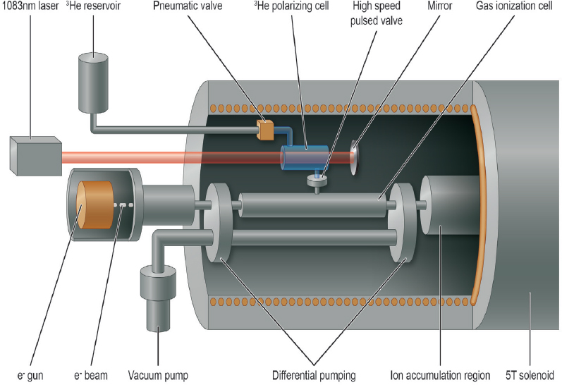
A BNL-Massachusetts Institute of Technology (MIT) collaboration is working on development of a polarized 3He ion source using the existing EBIS at RHIC. 3He atoms are polarized via optical pumping10 in a glass cell at a pressure of 1 mbar and directed into the EBIS vacuum system. An intense, 30 keV electron beam completely ionizes the polarized atoms, which are then electrostatically confined in the EBIS. By pulsing high voltage electrodes, 3He++ ions can be extracted. The design goal for the source is 1 × 10¹² 3He++/s at 70 percent polarization.
Successful tests of polarizing 3He in a high magnetic field have led to the development of the Extended EBIS upgrade where 3He is polarized in a second 5 T solenoid, as shown in Figure 4.11. This upgrade will also improve the ionized gold Au32+ production, prompting the construction to be completed in two phases. Phase 1 will focus on a 50 percent increase in Au32+ production and gas injection for the RHIC run starting January 2019. Phase 2 will be the polarized 3He++ upgrade.
Development and Benchmarking of EIC Simulations
An essential element of the EIC design process is the development of new and adaptation of existing simulation tools that can validate the many novel concepts of the proposed EIC designs, before critical technical decisions are taken. Both EIC accelerator designs require beam parameters and operational modes that present a significant extrapolation from state-of-the-art colliders and have never been demonstrated experimentally. To establish the feasibility of these concepts, validation through self-consistent, start-to-end simulations is essential. In turn, the simulation codes should be validated through benchmarking against experimental data. Specific modes of operation which require the development of new simulation codes include beam-beam interactions with crabbed beams in asymmetric e-p collisions and bunch-by-bunch swap out injections of high-intensity electron bunches during the collision process. The development of a central simulation toolbox that can be shared by all design teams is a worthwhile undertaking as it can be broadly applicable to other accelerator designs.
___________________
8 Report of the Electron Ion Collider Advisory Committee, November 2-3, 2009.
9 Report of the Community Review of EIC Accelerator R&D for the Office of Nuclear Physics, February 13, 2017.
10 F.D. Colegrove, L.D. Schearer, and G.K. Walters, 1963, Polarization of He3 gas by optical pumping, Phys. Rev. 132:2561.
DETECTOR TECHNOLOGIES
Measurements at an EIC rely crucially on highly capable detectors to observe the scattered electrons and any other particles scattered or produced in the collisions of the electron and ion beams. The range of EIC beam energies, ion species, collision rates, and collision characteristics of the processes of interest each present particular challenges for the design of such detectors, as do the envisioned measurement accuracies, including those of luminosity and polarization. The successful development of suitable EIC detectors relies crucially on HERA experience and on technological developments for other large-scale detectors in high-energy and nuclear physics, in particular those at the LHC and those envisioned for the ILC. Many of the needed detector technologies will thus have been used or demonstrated prior to the EIC. Optimized and tightly integrated EIC detectors will nevertheless require a sustained program of dedicated R&D.11
___________________
11 Brookhaven National Laboratory, in association with JLab and the DOE Office of Nuclear Physics, announced a generic detector R&D program in 2011 that has attracted active participation from the EIC user community.
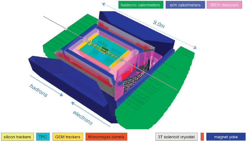
The need for high luminosity at an EIC, for example, presents conflicting demands of having to position beam focusing elements close to the interaction point while also leaving enough space for a well-integrated set of instruments that jointly form the central detector to fully characterize the beam collision products or events. The key challenge is thus to make the central detector as compact as possible, while retaining large acceptance and the full suite of particle identification and measurement capabilities. The topology of the beam collision events presents further challenges. The particles are scattered or produced over a wide range of angles, ranging from just a few fractions of a degree from the ion beam direction to a few fractions of a degree from the electron beam direction, thus requiring a detector that covers a similarly wide range. This range, or acceptance, well exceeds that of the existing and planned detectors at JLab and at RHIC. Like the angles, the energies of the scattered electrons span a broad range from just a small fraction of the EIC electron beam energy up to the ion beam energy. The need for high fidelity in the measurements restricts the amount of material that can be used in the innermost parts of the central detector and imposes stringent demands on detector resolutions. Many measurements require that the handful of hadrons produced in a typical beam collision at the EIC are identified, posing yet further challenges. Several candidate detector concepts have been put forward to meet the science needs for both the JLEIC and eRHIC design options. Figure 4.12 shows an example of a central detector concept for the eRHIC design option. Its integration in the interaction region is shown in Figure 4.3.
Large acceptance “electromagnetic calorimetry” features prominently in each of the concepts, driven first and foremost by the need to measure the scattered electron energy. The technology choices are informed primarily by energy resolution requirements, which are most stringent in the region along the forward going electron beam. Dense and fast lead tungstate crystals (PbWO4), studied extensively as part of R&D for the Compact Muon Solenoid (CMS) and Anti-Proton Annihilations at Darmstadt (PANDA) experiments, are a prime candidate for this region because of their superior energy resolution. Modules of tungsten powder with scintillating fibers, as developed initially within the Solenoidal Tracker at RHIC (STAR) collaboration, are being considered for the less demanding regions of the detector, as are more conventional choices. Established technologies are chosen typically also for hadronic calorimetry.
The detector concepts also feature large acceptance and low-mass “charged particle tracking” between the interaction point and the calorimeters. A high-rate time projection chamber (TPC), possibly complemented with large cylindrical MicroMegas detector elements, is an attractive option, as are barrel layers based on thinned complementary metal-oxide-semiconductor monolithic active pixel sensors (MAPS). MAPS have been studied extensively as part of the inner tracking systems of the STAR and A Large Ion Collider Experiment (ALICE) experiments
and for other applications—for example, in cryo-electron microscopy to study bio-molecules. The tracking in the challenging regions along the EIC beam directions require suitably optimized arrays of disks. Options include the aforementioned MAPS as well as gas electron multiplier technology, which has been greatly developed since its inception and is now used in numerous applications.
The broad range of hadron total momenta and the relatively compact central detector designs require consideration of a similarly broad range of technologies for particle identification (PID), a key capability for essentially all but the inclusive measurements at the EIC. A TPC, a prime candidate for charged particle tracking, can also provide charged particle identification via measurements of the particle specific energy depositions as the particle traverses the TPC gas. A high-performance Detecting Internally Reflected Cherenkov light within a solid radiator, and high-resolution time-of-flight technologies are being pursued as well, as are Ring-Imaging Cherenkov technology with aerogel and gas radiators. Reaction channels producing hadrons containing charm or beauty quarks can be reconstructed topologically by observation of their displaced decay vertices with precision silicon vertex trackers, MAPS again being a prime technology candidate.
Such reaction channels can also be tagged via observation of the semi-leptonic decays into electrons, positrons, or muons. Some of the central detector design concepts thus entertain the possibility of muon chambers at the outermost radii.
In addition to the central detector, it is crucial to integrate far-forward instrumentation into the interaction region design of the collider (see Figure 4.3) for exclusive as well as diffractive measurements. The scattered proton in exclusive electron-proton reactions can be measured with silicon-based trackers in “Roman Pot” stations that are used to measure the total cross section of two particle beams in a collider. These stations are integrated into the ion beam-line design at carefully chosen locations where the beam size is minimized and the scattered protons can be analyzed from the dispersion through dipole magnetic fields of the ion ring. Instrumented Roman Pot stations with suitable acceptance can serve also to tag spectator protons from the break-up of deuterium or 3He ion beams, whereas heavier ion beams require a dedicated spectrometer or zero-degree hadronic calorimetry. Detailed study of the remnants of the beam ions after their collision with the beam electrons has thus far not been emphasized as a core part of the EIC science program, but would present further challenges for EIC instruments.
Precision measurements of electron and hadron beam polarization12 and collision luminosity are essential to the EIC core science program and require ancillary instrumentation. The methods and techniques for these measurements appear known to be able to achieve the core EIC science objectives, although it should be noted that a number of EIC measurements are limited by systematic rather than statistical uncertainties. The instrumentation associated with luminosity and polarization measurements is typically located very close to the beams and can, in the case of the electron beam, be designed to considerably expand the acceptance of the central detector for scattered electrons to very shallow angles, a region of considerable scientific interest dominated by photo-production processes.
___________________
12 Measurement of EIC hadron beam polarization is likely to adopt the methods employed at RHIC, which have achieved 3 to 4 percent accuracy and will take place in a dedicated location away from the central detectors.


