CHAPTER FIVE
Direct Air Capture
INTRODUCTION
The results of recent integrated assessment modeling (Fuss et al., 2013) have made clear the need to include negative emissions technologies (NETs) as one component in a portfolio of solutions (e.g., mitigation, energy efficiency, renewables, fuel-switching) to prevent greater than 2°C global warming by 2100. Among these NETs is the direct removal of carbon dioxide (CO2) from the atmosphere, commonly referred to as direct air capture. To be considered a NET, direct air capture systems must sequester the captured CO2 on a timescale that positively impacts climate change. Currently, the only reasonable approach to store captured CO2 is geologic sequestration, which is covered in Chapter 7.
Direct air capture has received significant attention in the public media because it provides a means to reverse CO2 emissions, appears to be a relatively “easy fix” to climate change, and is a relatively new and high-tech NET. In addition to negative emissions potential, direct air capture systems benefit from their inherent flexibility of placement, which can reduce the need for pipelines1 from the capture site to the sequestration reservoir. Furthermore, direct air capture systems have the flexibility to produce CO2 for the commodity market at a desired purity. However, thermodynamics sets a lower bound on the energy required to separate a mixture of gases. Dilute streams are more difficult to separate and require more energy than more concentrated mixtures. A discussion of the thermodynamic limitations appears in Appendix D. The direct air capture approaches described in this chapter are technically feasible, but because CO2 in air is ~300 times more dilute than in flue gas from a coal-fired power plant, the separation process for the same end CO2 purity will likely be more expensive than capture from fossil fuel power plants.
CO2 removal from gas streams is an important component of many industrial processes. The choice of removal technology is governed by the concentration and pressure of the gas stream. Physical solvents are used at high concentrations in natural gas processing and chemical production. Lower concentrations require use of chemical
___________________
1 Approximate cost of CO2 transportation via pipeline is $2.24/tonne CO2 per 100 km of dedicated pipeline (DOE, 2015a).
bases that react with CO2, a Lewis acid. Among the simplest of these are hydroxides and amines. These can be introduced either as components of a liquid (usually aqueous) solution, or as functional groups on the surface of a high surface area solid material. Thus, CO2 can be captured from dilute gas streams, including air at ~400 ppm CO2, by contact with basic liquids and solids. However, capture is only the first step. For manufactured direct air capture systems2, the capture agent, either liquid or solid, must be able to release CO2 at conditions of temperature and pressure that are accessible with low energy input, so that the capture agent can be used repetitively, and to prepare CO2 for some form of secure sequestration. Capture generally happens spontaneously using these chemical agents, and the most significant energy costs are incurred in the step that recovers and concentrates the captured CO2. Capture is generally an exothermic process, and desorption for concentration is an endothermic process.
This chapter evaluates two types of direct air capture CO2 separation processes: one employing liquid solvents and one utilizing solid sorbents. Material and energy balances are carried out and compared to quantify the net reduction of CO2 from the atmosphere depending on the energy sources assumed (e.g., renewables, nuclear, natural gas, or coal). This analysis helps to identify the technical challenges of each capture process to inform development of a future research and development (R&D) agenda. A discussion and analysis of CO2 compression, transport, and subsequent geologic sequestration are covered separately in Chapter 7 on Geologic Sequestration and Appendix F. This chapter also provides estimates of the annual CO2 reduction potential, cost, and capacity associated with each capture process.
___________________
2 The focus of this chapter is on manufactured direct air capture systems, which utilize chemical or physical processes that are designed to capture CO2 from the ambient air. These systems differ from those that rely on natural phenomena such as CO2 uptake by plants or minerals in the natural environment.
often used different system boundaries; for example, not all studies accounted for all the steps needed for a complete cycle. Some utilized generic correlations for process operations, while others performed out detailed optimizations of specific systems. As progress continues on pilot and demonstration plants, more accurate costs can be expected to become available.
BACKGROUND
Economics (Literature Review)
The cost of carbon capture for direct air capture systems has been a contentious issue. The estimates found in the literature span an order of magnitude, from $100 to $1,000/tCO2 (Ishimoto et al., 2017). These estimates represent the costs of CO2 captured and not the costs of net CO2 removed from the atmosphere, with these costs tending to render direct air capture among the most expensive atmospheric CO2 removal approaches. One challenge to comparing estimates is that earlier reports
Estimates at the high end of the cost spectrum ($1,000/tCO2, House et al., 2011) were not based on a specific technology. Rather, they were based on direct air capture energy requirements and application of second-law efficiencies to the calculation of minimum separation energy based on 75 percent air capture and 95 percent CO2 product. A range of energy resource costs from wind to natural gas were considered, leading to an approximate upper estimate of $1,000/tCO2.
Estimates of $641-819/tCO2 based on a benchmark liquid system were provided in the first report to assess direct air capture, produced by the American Physical Society (APS) (Socolow et al., 2011). Although comprehensive in its analysis, that report’s benchmarking system introduced key limitations. This system conceptually adapted the technology for CO2 capture from flue gas streams—countercurrent flow of gas and liquid caustic solutions in a packed column—to CO2 capture from air. Because air has much lower concentrations of CO2, the volume of gas flow per ton of CO2 captured is much larger and the power requirements to overcome the pressure drop in the vertical packed tower configuration contribute to significant capital and operating costs. Although optimization of the operating conditions for this design could reduce costs somewhat (estimated as $528-579/tCO2 [Mazzotti et al., 2013] and $309-580/tCO2 [Zeman, 2014]) the basic geometry and gas-liquid contact scheme would remain the same. Such designs are now recognized as not broadly applicable to direct air capture systems.
As highlighted by several studies, altering the flow configuration to reduce pressure drop can dramatically reduce capture costs compared to the APS benchmark system, which is based on a more conventional approach that mimics post-combustion capture absorber technology. Holmes and Keith introduced a combination of a cross-flow scheme for the gas relative to the falling liquid and a novel scheme involving the co-capture of CO2 from air combined with an oxy-fired natural gas regeneration in a carbonate-based capture system. This configuration led to estimates between $336-389/t CO2 (Holmes and Keith, 2012) and $93-220/tCO2 (Keith et al., 2018). For solid adsorbents, low pressure–drop configurations analogous to the “honeycomb” structure of monoliths for automobile catalytic converters and other ultra-low-pressure–drop configurations are preferred motifs (Realff and Eisenberger, 2012). These novel configurations will require further testing and demonstration to realize the lower price points.
Laboratory studies of processes based on both solid and liquid sorbents have tended to estimate lower operating costs. Examples include amine-functionalized sorbent processes estimated at $82-155/t CO2 (Kulkarni and Sholl, 2012), though this study only considered operating costs. Earlier cost estimates based on aqueous chemical capture designs were similar at $60-145/t CO2 (Stolaroff et al., 2008) and $165/t CO2 for a complete system excluding sequestration (Keith et al., 2006). However, caution should be taken when making comparisons across studies because the completeness of the system considered, and the purity of the CO2 stream produced, vary among them.
Commercial Status
Several companies are currently working to commercialize direct air capture systems (Table 5.1). These companies are primarily focused on units that operate on the scale of 1 Mt/y CO2 capture from the air and are primarily privately funded.
Many direct air capture systems have been proposed. These can be distinguished by characteristics including the choice of liquid solvent or solid sorbent, method for CO2 release/capture (regeneration), and purity of the output CO2 stream.
Although pure (> 99 percent) CO2 is desired for geological storage or sequestration, more dilute streams containing 3-5 percent CO2 can still be useful for supply to enclosed greenhouses and algae farms (Wilcox et al., 2017). Although commercial entities need to monetize CO2 to offset R&D costs and grow their business, if CO2 is separated from air for utilization, then it must be sequestered on a timescale that positively impacts climate to be considered a NET. Of the companies listed in Table 5.1, all but Carbon Engineering utilize capture by amine (or ammonium)-based solid sorbents, although some are considering other kinds of structured solid sorbents in their continued development. Carbon Engineering’s process involves aqueous hydroxide solutions that react with CO2 to precipitate a carbonate salt. Most approaches rely on heating or a combination of heat and vacuum to release captured CO2 from its bound state on the solid sorbent or, in the case of the precipitate in the Carbon Engineering process, to thermally decompose the carbonate. The resulting alkaline oxide, or hydroxide in the latter case, is then re-dissolved in the aqueous solution, thereby restoring its CO2 uptake capacity. Alternative methods of regenerating solid sorbents have been advanced by Wang et al. (2013), as well as companies such as Infinitree (humidity swing). In the latter case, after capture under relatively dry conditions, exposure of the CO2-saturated sorbent to humid air under mild vacuum causes release of CO2.
TABLE 5.1 Companies Working to Commercialize Direct Air Capture Systems
| Company | System Type | Technology | Regeneration | Purity/Application | Scale |
|---|---|---|---|---|---|
| Carbon Engineering | Liquid solvent | Potassium hydroxide solution/calcium carbonation | Temperature | 99% | Pilot 1 t/d |
| Climeworks | Solid sorbent | Amine-functional-ized filter | Temperature or vacuum | 99% w/dilution depending on application | Demonstration 900 t/y |
| Global Thermostat | Solid sorbent | Amine-modified monolith | Temperature and/or vacuum | 99% | 1,000 t/y |
| Infinitree | Solid sorbent | Ion-exchange sorbent | Humidity | 3-5% algae | Laboratory |
| Skytree | Solid sorbent | Porous plastic beads functional-ized with benzylamines (Alesi and Kitchin, 2012) | Temperature | Air purification, greenhouses | Appliance |
At the time of writing, all the companies have technologies that are either in the laboratory stage or have advanced to one-off pilot or demonstration plants. Climeworks has advanced the farthest, operating a 900 t/y demonstration plant in Switzerland where CO2 is used for various applications, rather than stored in geologic reservoirs.
ANALYSIS: ENERGETICS, CARBON FOOTPRINTS, AND COSTS
This section presents the Committee’s analyses of the energetics, carbon footprints, and economics of direct air capture systems based on liquid solvents and solid adsorbents. Both analyses were based on the following baseline assumptions:
- Plant capture rate from air = 1 Mt/y CO2
- Concentration in air = 400 ppmv CO2
- Volumetric flow rate ≥ 58,000 m3/s air
- Capture fraction from air ≥ 60+ CO2
- Concentration of product ≥ 98 percent CO2
- Emission factors
- Heat from natural gas = 227 g CO2/kWh
- Heat from coal = 334 g CO2/kWh
- Heat from nuclear = 4 gCO2/kWh
-
- Heat from solar = 8.3 gCO2/kWh
- Electricity from grid (U.S. average) = 743 gCO2/kWh
- Electricity from natural gas = 450 gCO2/kWh
- Electricity from coal = 950 gCO2/kWh
- Electricity from nuclear = 12 gCO2/kWh
- Electricity from solar = 25 gCO2/kWh
- Electricity from wind = 11 gCO2/kWh
- Plant life = 10 years3
When designing a plant capable of capturing 1 Mt/y CO2 from the air, one has to carefully consider the energy resources that will power the plant to determine the net removal of CO2 from the air. For instance, if fossil fuels supply the energy in the absence of conventional carbon capture and sequestration (CCS), the net removal of CO2 from the air may be significantly reduced. When comparing the costs of direct air capture across varying boundary conditions, the estimates for direct comparison can be aligned through the use of a cost factor, represented by:
Cost Factor = 1/1-x
such that x is the CO2 emitted per CO2 captured. As x approaches 1, or for every ton of CO2 captured, 1 ton is released, the factor approaches infinity, as does the cost. In contrast, as x approaches zero, the cost of net CO2 removed becomes closer to the cost of capture. Examples of technologies that may lead to an x near zero are those that use low-carbon energy resources to supply the required heat and power to operate the system, which may be unique for a given direct air capture approach. For example, the liquid solvent approach requires temperatures of up to 900°C for regeneration. Technologies that may achieve this temperature include concentrated solar power towers (DOE, 2013), combustion of low-carbon hydrogen, PV or wind-sourced electric heating, and alternative designs of nuclear including high-temperature gas-cooled reactors (Harvey, 2017). In comparison, the solid sorbent–based approach requires significantly lower temperatures for regeneration (i.e., < 150 °C). Hence, the options for providing low-carbon energy differ but may include geothermal and light water nuclear reactors. It is also important to consider the embodied emissions of the materials required to build a plant capable of operating at 1 Mt CO2 per year. Although the embodied emissions are not included in the current analyses, the amount of steel and cement for these plants may be nonnegligible. The current analysis makes clear that direct air capture, if fueled by low-carbon energy pathways, will have the greatest impact. However, fueling direct air capture plants with low-carbon energy resources in
___________________
3 Same as used by the U.S. Department of Energy for baseline power plant studies, such as in Draucker et al., 2010.
place of using those resources to directly replace fossil fuel–based point-source emitters requires careful consideration.
The design of both direct air capture approaches included an air contactor and regeneration facility. In general, a practical process requires five key attributes: (1) low-cost air contactor to allow for a contactor area that is large enough to minimize pressure drop, because the low concentration of CO2 in air requires passage of large gas volumes through the contactor; (2) optimal CO2-sorption thermodynamics, which relates to having a sorption isotherm with suitably high CO2 uptake at CO2 partial pressures below 500 ppmv to minimize sorbent inventory and overall size of the process. The need for high CO2 uptake at low partial pressures suggests that sorbents need strong, chemical interactions with CO2, in contrast to separation processes that operate at higher CO2 partial pressures, where sorbents employing weaker, physical interactions may be used; (3) rapid sorption/desorption kinetics, which results in fast sorption and desorption, faster cycling, and therefore less sorbent needed for the same output; (4) low sorbent regeneration energy so that the CO2 binding energy is high enough to achieve a good uptake capacity, but not so high that endothermic sorbent regeneration energy requires unacceptably high regenerator costs. Furthermore, effective process designs will minimize the thermal mass of equipment that is repeatedly thermally cycled between sorption and desorption—that is, the sensible heat of the process should be minimized; and (5) low capital costs, which applies to virtually any process but is particularly relevant for direct air capture systems, with the lifetime of sorbent media posing a potentially important capital cost for some designs.
The committee followed different approaches to analyze the liquid solvent and solid sorbent direct air capture systems described below. The liquid solvent systems analysis is derived from a conceptual process design published by Carbon Engineering (Holmes and Keith, 2012; Keith et al., 2018). The committee conducted its analysis before Keith et al. published in 2018, but after careful examination of that work, determined that its analysis aligns closest with the design “C” configuration, which omits the onsite power island and instead uses grid electricity to supply all electrical work, suitable in regions with available low-carbon electricity. However, the C configuration assumes compression of CO2 to 15 MPa, and compression is not included in the committee’s analysis. Compression results in an energy of 0.48 GJ/tCO2 and cost of $8/tCO2, assuming an electricity cost of $60/MWh—leading to additional emissions of 0.1 Mt CO2 for every Mt CO2 captured, assuming an average grid emissions factor of 744 kgCO2/MWh.
In particular, for the regeneration of Carbon Engineering’s capture material, the heat is sourced by burning natural gas in an oxygen-fired kiln in which CO2 is produced by
both the combustion of natural gas and the calcination of CaCO3, the material that is partially responsible for removing CO2 from the air. The committee’s analysis of this process considers the overall energetics and economics of the combined process, as well as that obtained by direct air capture only, excluding the CO2 produced from fossil fuel combustion. Several companies are pursuing solid sorbents systems (e.g., Climeworks, Global Thermostat, and Skytree), each developing their own unique proprietary process with different design features. Therefore, rather than analyzing a specific process, a generic sorbent-based process is considered, and key process parameters varied to provide a range of energetic and process costs.
Liquid Solvent Systems
Process Description
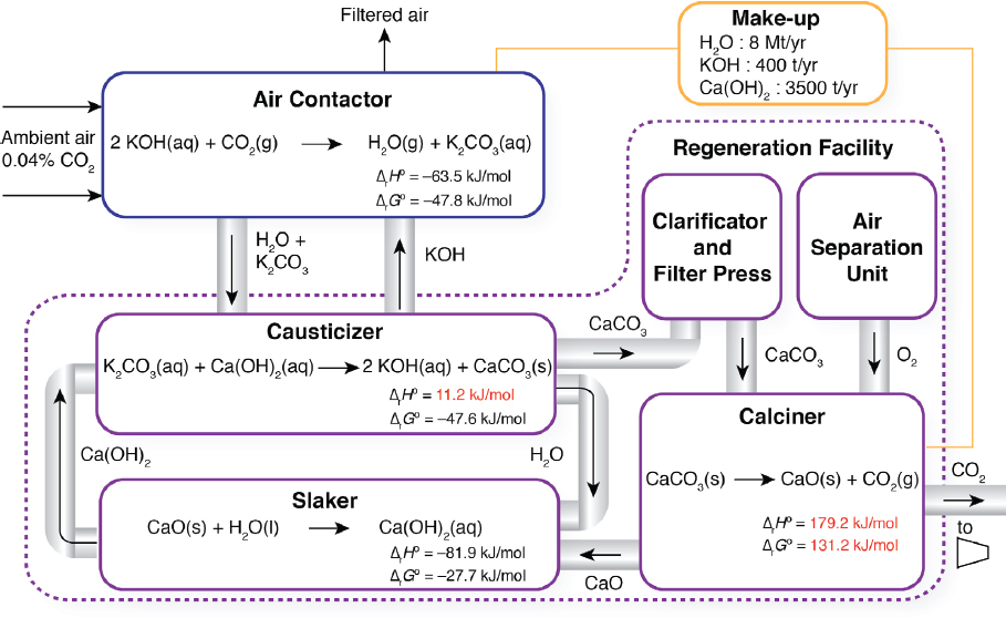
The two major components of a liquid solvent direct air capture process are the air contactor and regeneration facility (Figure 5.1). In this process, an aqueous potassium hydroxide solution (KOH) reacts with the CO2 from the air to form water and potassium carbonate (K2CO3) in an air contactor. The potassium carbonate aqueous solution is then fed to a causticizer, where it is reacted with calcium hydroxide (Ca(OH)2) to form calcium carbonate (CaCO3) precipitate. The CaCO3 slurry is then fed to clarificatory and filter press to remove water, before it is fed to a calciner where the CaCO3 precipitate is heated with natural gas in an oxy-fired kiln to about 900°C thereby producing solid calcium oxide (CaO) and high-purity CO2 gas that can be compressed and transported for long-term sequestration.
Unit Operations
Air Contactor
The air contactor is used to contact the air with a KOH aqueous solution such that CO2 reacts to produce K2CO3:
2KOH + CO2 → H2O + K2CO3
The ambient air enters the contactor at 400 ppm and exits with 75 percent CO2 captured in the solvent as K2CO3. Because of the high stability of this product species, a caustization step is required to react K2CO3 with Ca(OH)2 to form calcium carbonate CaCO3, regenerating the KOH solution for reuse in the contactor.
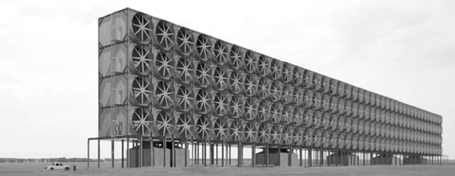
Contactor Sizing: In the air contactor, air is blown using fans over PVC-based packing material like that used in industrial cooling towers, as depicted in Figure 5.2. The solvent is a 1 M KOH aqueous solution that is sprayed uniformly over the packing material. The packing material assumed is Brentwood XF12560. Holmes and Keith (2012) determined that a capture fraction of 0.75 CO2 in air was optimal based on their solvent-based separation process. With an air velocity of 1.5 m/s and 75 percent CO2 capture from air, the contactor area needed to separate 1 Mt/y CO2 is 38,000 m2. The largest commercial packed towers have areas of about 100 m2, which would indicate the need to construct hundreds of towers to achieve 1 Mt/y CO2. Because of this challenge, Holmes and Keith have proposed adopting technology used in large-scale cooling towers and waste treatment plants. Their optimal air contactor design is approximately 20 m × 8 m × 200 m, and 10 contactors would be needed to capture 1 Mt/y CO2, a considerable improvement over a conventional packed tower. Moreover, the packing volume for their system is estimated at 20,000 m3, compared to a large cooling tower volume of 10,000 m3 and a conventional packed tower of about 285 m3. These considerations highlight that an optimized direct air capture contactor design
will significantly differ from that of a conventional coal or natural gas post-combustion carbon capture plant.
Pressure Drop: When calculating the pressure drop, one has to consider the packing material composition (e.g., metal, plastic, ceramic) in addition to the nature of the air flow through the wetted packing material. For post-combustion applications, the flow is often modeled as counter-current (Mazzotti et al., 2013; Socolow et al., 2011), while in the work of Keith et al. (2012, 2018) it is modeled in a cross-flow configuration. The literature provides several pressure-drop correlations for conventional metal packing material with counter-flow configurations, but does not appear to do so for pressure-drop correlations for the PVC packing material with the cross-flow configuration as described in Keith et al. (2012, 2018). For this reason, in the Committee’s analysis, a range in fan power energy consumption is established by considering separately the pressure drop associated with stainless steel and PVC packing materials. In the work of Keith et al. (2012, 2018), the pressure-drop across the packed tower is based on the following correlation developed specifically for the PVC packing material, Brentwood XF12560:
ΔP = 7.4Dv2.14
where ΔP is the pressure drop in (Pa), D is the column depth in (m), and v is the air velocity in (m/s). Based on Holmes and Keith’s design (v = 1.5 m/s, D = 6–8 m), the resulting pressure-drop ΔP = 106–141 Pa (1.0-1.4 mbar).
SOURCE: Holmes and Keith, 2012.
Mazzotti et al. (2013) showed that a novel, stainless steel packing material designed specifically for post-combustion capture may achieve a ΔP = 380 bar (v = 2.57 m/s, D= 3.6 m). This pressure drop was derived for a counter-current flow contactor where air velocity and capture fraction were treated as optimizable variables. Implications behind the choice of packing material will be discussed in greater detail in the process economics section.
Fan Work: From the pressure drop, the fan power (MW) required to drive 58,000 m3/s flowing air through the contactor can be calculated from:
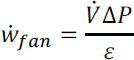
where ![]() is the volumetric flow rate (m3/s) and ɛ is the fan electrical efficiency (60 percent assumed). This yields an air contactor fan work = 10-37 MW. Thus, for a carbon capture rate of 1 Mt/y CO2, the fan energy required is 0.32-1.18 GJ/t CO2 (14.2-52.5 kJ/mol CO2) captured. This equates to 0.073-0.269 Mt/y CO2 emissions from coal-fired power and 0.044–0.160 Mt/y CO2 from natural gas-fired power, resulting in an average annual net CO2 capture of 0.83 Mt/y and 0.90 Mt/y for coal and natural gas power to the fan, respectively.
is the volumetric flow rate (m3/s) and ɛ is the fan electrical efficiency (60 percent assumed). This yields an air contactor fan work = 10-37 MW. Thus, for a carbon capture rate of 1 Mt/y CO2, the fan energy required is 0.32-1.18 GJ/t CO2 (14.2-52.5 kJ/mol CO2) captured. This equates to 0.073-0.269 Mt/y CO2 emissions from coal-fired power and 0.044–0.160 Mt/y CO2 from natural gas-fired power, resulting in an average annual net CO2 capture of 0.83 Mt/y and 0.90 Mt/y for coal and natural gas power to the fan, respectively.
Water Loss: Depending on the molarity of the hydroxide solvent and the relative humidity, the water loss in the air contactor could be 1-30 mol/mol H2O per CO2 captured. Stolaroff et al., 2008 showed that increasing the concentration of hydroxide resulted in less water loss. Specifically, water loss was nearly eliminated for a ~ 7.2 M NaOH at 15°C and 65 percent relative humidity. However, Holmes and Keith (2012) estimated the minimum hydroxide concentration to mitigate water loss was 2 M KOH. Stolaroff et al., 2008 showed that a water loss of 20 mol/mol H2O per CO2 captured is typical for low concentration hydroxide solutions (e.g., 1.3 M) at 65 percent relative humidity. Thus, a liquid solvent direct air capture system with a 1 Mt/y CO2 capture rate will require the addition of about 8.2 Mt/y water to make up for water loss.
Solvent Pump
To calculate the work required to pump KOH for even distribution across the packing material, the pressure drop, volumetric flow rate, and liquid density are required. This information was not available for the system of Holmes and Keith (2012), but they presented a rule of thumb in that the energy required for fluid pumping is approximately 15 percent of that required of the fan energy. This equates to 0.048-0.065 GJ/t CO2
(2.13–2.84 kJ/mol CO2) captured. The additional CO2 generated by using coal or natural gas to generate electricity for solvent pumping results in 0.013 and 0.0077 Mt/y CO2, respectively.
Slaker
In the slaker, CaO reacts with H2O exothermically to regenerate Ca(OH)2, which is reused in the causticizer:
CaO + H2O → Ca(OH)2
Inert grit may be produced in the slaker, which impacts the efficiency of this step. Grit production depends on particle size, temperature, and the type of equipment used (Hassibi, 1999). Work for the slaking process has been estimated at 0.005 GJ/t CO2 (0.2 kJ/mol CO2) (Baciocchi et al., 2006), while efficiencies in the literature range from 0.95 to 0.99 (Emmett, 1986). Using an average efficiency, slaking work contributes additional emissions of 0.001 and 0.0007 Mt/y CO2 when the electricity is sourced from coal and natural gas, respectively. Despite the exothermic nature of the slaking reaction and heat exchange that occurs between the slaking and causticization steps, this low-grade heat may not be easily integrated and becomes difficult to consider in the cumulative energy for regeneration.
Causticizer
In the causticizer, an K2CO3 aqueous solution is pumped from an exit stream in the air contactor and reacted with Ca(OH)2 to make CaCO3 and regenerate KOH for reuse in the air contactor:
H2O + K2CO3 + Ca(OH)2 → 2 KOH + CaCO3
Typical causticization efficiencies for sodium hydroxide (KOH efficiencies are lacking in the literature) range from 0.8 to 0.9, which means that energy requirements will increase to account for the additional processing needed to compensate for nonideal conversions (Mahmoudkhani and Keith, 2009). However, the causticization step has negligible work requirements compared to other steps in the regeneration cycle (Baciocchi et al., 2006); thus, incremental changes in work due to causticization efficiency are manifested in downstream processes (e.g., clarification and filter press).
Following the causticization reaction, the supernatant KOH (aq) solution is clarified, mixed with additional reclaimed solvent and pumped back to the absorber. The
required work in the clarification step is estimated to be 0.109 GJ/tCO2 (4.8 kJ/mol CO2) assuming ideal conversion efficiencies in upstream processes (Baciocchi et al., 2006). Adjusting this work value for realized slaking and causticization efficiencies results in emissions of 0.025 and 0.015 Mt/y CO2 for coal and natural gas, respectively. Precipitated CaCO3 is filtered, thickened, and pressed in preparation for transport to the kiln for calcination. Heating and drying of the CaCO3 is necessary to remove as much water content as possible before passage to the energy-intensive calcination step. This preparation is also energy intensive, requiring an estimated 3.18 GJ/tCO2 (140 kJ/mol CO2), or the equivalent of 0.30 and 0.20 Mt/y additional CO2 emissions using heat derived from coal and natural gas, respectively.
Calciner
Following filtration, clarification, and drying, CaCO3 must be heated to high temperatures (~ 900°C) in a calciner to form calcium oxide (quicklime) and highly concentrated CO2:
CaCO3 → CaO + CO2
After calcination, the quicklime is returned to the slaker, where it reacts with water exothermically to regenerate Ca(OH)2 and heat the slaking solution to about 95°C (Baciocchi et al., 2006). Although low-grade heat such as this is often difficult to integrate, a separate CaCO3 steam drying process using heat recovered from lime hydration could offset thermal requirements for drying by 2.39 GJ/t CO2 (105 kJ/mol CO2) (Zeman, 2007). In addition, calcination efficiencies of over 0.9 have been reported in the literature (Martinez et al., 2013; Stamnore and Gilot, 2005). Heat requirements reported in the literature (Baciocchi et al., 2006; Zeman, 2007) for the calcining process range from 6 to 9 GJ/tCO2 (264-396 kJ/mol CO2). This includes an efficiency factor of 0.75 for the direct use of thermal energy.
Because of this large thermal requirement, CO2 emissions associated with traditional calcination processes are significant, ranging from 0.38 to 0.57 and 0.56 to 0.84 Mt/y CO2 for natural gas and coal firing, respectively. To minimize CO2 generated in the direct air capture process, any thermally generated CO2 could, in theory, become co-captured with that from ambient air. However, the balance of post-kiln exhaust is largely nitrogen, and if the end goal is to produce a near-pure (≥ 99 percent) CO2 stream, then additional CO2 separation equipment is required. Oxygen-fired (oxy-fired) kilns can obviate the need for additional CO2 separation equipment, because they produce an exhaust that is composed of only CO2 and H2O, allowing the production of a near-pure CO2 stream after the water is condensed out. For heat recovery
from the calciner, a heat-exchanger is used to cool the 900°C flue gas exiting to 200°C with the incoming gas. Then, the 200°C flue gas is passed through a condenser and further cooled to 30°C. Pure oxygen for the oxy-fired kiln is separated from air using an air separation unit (ASU), where its electric requirements are 0.30 GJ/t CO2 (13.2 kJ/mol CO2), leading to a footprint of 0.068 and 0.041 Mt/y CO2 using electricity-derived from coal and natural gas firing, respectively.4
Chemical Make-up
Reagent loss may occur at several points in a liquid solvent direct air capture process. Because of the nature of direct air capture, foreign contaminants may enter the absorber (e.g., insects, birds, particulate matter, sulphur oxides [SOx] and nitrogen oxides [NOx]) and then accumulate and combine with Ca-ions to form undesirable products. Further Ca-ion loss can occur during filtration and kiln firing. It is preferred to make up Ca-ion loss with CaCO3 because of its relatively low cost ($200/t delivered) and smaller carbon footprint than other lime products, such as quicklime (CaO) and slaked lime (Ca(OH)2).5 In addition, KOH may be lost in the absorber through aerosol formation and spray drift (Keith and Holmes, 2012. Operational expenditures for chemical makeup have been estimated to be $0.90/tCO2 captured (Socolow et al., 2011). Assuming this cost is split into $0.20/tCO2 for KOH (aq) and $0.70/tCO2 for CaCO3(s), results in make-up requirements of 400 t KOH/y6 and 3,500 t CaCO3/y, respectively. Given that KOH is produced in the energy intensive chloralkali process (7 GJ/t KOH), make-up from KOH production yields a footprint of 590 t/y CO2. Emissions from CaCO3(s) makeup may be attributed to vehicle emissions from delivery (0.11 kg/t-mile CO2), accounting for the round-trip, and any additional disposal required from waste buildup in the loop.7
Mass and Energy Balance
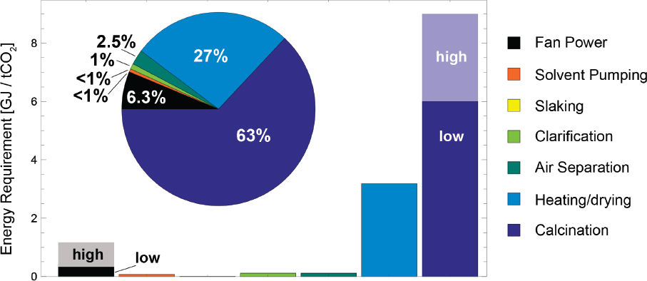
Estimated energy requirements for liquid solvent direct air capture systems are provided in Table 5.2 and depicted in Figure 5.3, and totals of 0.74-1.66 GJ/t CO2 and
___________________
4 Based on 200 kWh per tonne O2 produced in the ASU, and 0.56 mol O2 per mol CaCO3 supplied to the calciner.
5 Emissions from CaCO3 mining range from 1.5 to 80 kWh/t, resulting in negligible CO2 emissions when compared to other steps outlined in this section.
6 Based on a bulk purchase price of $506.5/t NaOH (Integrated Environmental Control Model [IECM]).
7 This disposal may be considered analogous to reclaimer waste disposal in MEA regeneration ($260/t) (IECM).
9.18-12.18 GJ/t CO2, for electricity and thermal energy requirements, respectively. The fans, pumps, slaker, causticizer/clarifier, and air separation units are all assumed to run off of grid-sourced electricity, while the heater/dryer and calciner represent the thermal requirements of the overall system. As shown in Figure 5.3, collectively, the energy required from running the electric components of the system totals from 6 to 18 percent of the entire energy demand for the process. In particular, the dominant energy-intensive component of this process is the thermal regeneration of CaO and subsequent production of high-purity CO2, followed by the step of heating and drying of CaCO3. These steps collectively reduce the net CO2 captured to between 0.11-0.42 Mt/y CO2 if natural gas is used as the thermal energy source and 0-0.11 Mt/y CO2 for coal. In other words, using coal as the thermal source results in nearly equivalent emissions of CO2 as that captured. These estimates include a thermal credit of 1.5 GJ/tCO2 from the cooling of the calciner exhaust unit. Because of the uncertainty associated with a well-defined system that could recover the heat generated from the hydration reaction of the steam drying process, this credit was not included in these estimates. This is also a primary difference between the analysis of the current work and that of Keith et al. (2018), because they assume significant heat integration resulting in an average thermal work requirement of 5.25 GJ/tCO2 compared to the lower bound of 8.4 GJ/tCO2 in the current work. Incorporating heat recovery methods as described in Zeman (2007), this requirement may be reduced to 6 GJ/tCO2. However, given the lack of clarity about heat integration approaches in the open literature, they were excluded from the current study. Further, because the calciner is oxy-fired, this approach in particular co-captures the CO2 from air in addition to that generated from burning natural gas for the heat source. Consideration of this particular approach reveals that an additional 0.38-0.57 Mt/y CO2 can be produced at high purity along with that captured directly from the air.
Assuming an initial atmospheric concentration of CO2 at 400 ppm at 25°C, the minimum work of capturing 75 percent of the CO2 at 98 percent purity is 0.45 GJ/tCO2 (20 kJ/mol CO2). Based on the energy requirements outlined for liquid solvent direct air capture systems, the “real” work is 8.2-11 GJ/t, leading to an exergy efficiency8 of 4.1-6.2 percent.
Process Economics
In assessments of the costs and benefits of direct air capture, an area of contention has been the broad range of costs reported in the literature. Comparing costs without
___________________
8 Exergy efficiency is defined as the ratio of minimum work to real work: Wmin/Wreal.
TABLE 5.2 Liquid Solvent Direct Air Capture System Unit Operation Energy Requirements and CO2 Generation
| Unit Operation | Energy Required (GJ/t CO2) | CO2 Generated (Mt/y) | |
|---|---|---|---|
| Natural Gas | Coal | ||
| Contactor fans | 0.32-1.18 | 0.044-0.160 | 0.071-0.095 |
| Solvent pump | 0.048-0.065 | 0.007-0.009 | 0.011-0.014 |
| Slaker | 0.005 | 0.0007 | 0.001 |
| Causticizer/clarifier | 0.109 | 0.015 | 0.028 |
| Air separation unit | 0.30 | 0.041 | 0.028 |
| Heater/dryer | 3.18 | 0.20 | 0.30 |
| Oxy-fired calciner | 6.0-9.0 | 0.38-0.57a | 0.57-0.85a |
| Exhaust gas cooling | -1.5 | -0.11 | -0.15 |
| Additional heat recoveryb | -2.4c | — | — |
| Total (w/o gas cooling credit) | 9.9-14 | 0.69-1.00 | 1.00-1.31 |
| Total (w/gas cooling credit) | 8.4-12.5 | 0.58-0.89 | — |
a Emissions co-captured with those from ambient air.
bHeat recovered from hydration of CaO for use in CaCO3 drying (Zeman, 2007).
c Neglected in process total.
first normalizing conditions and boundaries is misleading; thus, it is important to emphasize that the cost estimates presented here are for the separation and capture of CO2 from ambient air from modestly optimized, generic direct air capture systems operating at 75 percent capture with highly concentrated CO2 product (~ 98 percent purity), which is needed to minimize compression costs and volume requirements for geological sequestration. These cost estimates reflect the total annual economic penalty incurred for removing 1 Mt CO2 from air on a per ton CO2 captured basis. However, additional CO2 emissions can be generated in several of the steps required in direct air capture systems. It is important to account for these emissions directly in the avoided cost expression by assuming a penalty for any emissions generated. This cost of CO2 avoided is always higher than the cost of CO2 captured and approaches infinity as the amount of CO2 generated during capture approaches the amount captured. It is important to account for these emissions directly in the net cost expression by assuming a penalty for any emissions generated. This net cost of CO2 removed is always higher than the cost of CO2 captured and approaches infinity as the amount of CO2 generated during capture approaches the amount captured. The cost estimates presented here also vary by energy source and do not include costs for compression, transportation, injection, and sequestration.9
The estimated capital and operating costs for a 1 Mt/y CO2 liquid solvent direct air capture system are provided in Table 5.3. This cost analysis presents an optimistic scenario based on optimal parameters (for instance, Holmes and Keith [2012] and Keith et al. [2018]), where co-dependent parameters are jointly optimized to minimize system cost. Here, any literature values on installed equipment costs are taken directly, whereas direct equipment costs are multiplied by a 4.5 factor to convey total installed cost (Rudd and Watson, 1968). A realistic case is presented whereby parameters are set at their respective upper bounds as indicated in Table 5.3. A realistic worst-case scenario still aims to minimize cost through single- and joint-parameter optimization, but additional factors (e.g., higher cost of electricity, extent of heat integration, new technology multiplying factors, equipment quotes) elevate additional cost components, leading to a higher total cost. These estimates yield capture costs of $147-264/tCO2 for natural gas–fueled systems and $140-254/tCO2 for coal-fueled systems (Table 5.4). The estimated net costs per CO2 removed are $199-357/tCO2 for natural gas–fueled systems and approach infinity in the case of coal-fueled systems, because more CO2 is generated than captured.
___________________
9 Because costs for compression, transportation, injection, and storage for CO2 captured both through bioenergy with carbon capture and sequestration (BECCS) and direct air capture are assumed to be approximately the same, the report discusses them once in Chapter 7 and again Appendix F.
TABLE 5.3 Estimated Capital (CAPEX) and Operating (OPEX) Costs for a Generic Liquid Solvent Direct Air Capture System with a Capacity of 1 Mt/y CO2 Removal
| CAPEX | Cost ($M) | Comment |
|---|---|---|
| Contactor array | 210–420 | Lower bound: reported cost of air contactor array from Holmes and Keith (2012), based on optimal percent capture of 75% and bed depth of 6-8 m and PVC packing material at ca. $250/m3. Upper bound: projected cost of re-optimized Keith and Holmes configuration using stainless steel packing ($1,500/m3), shallow packing bed (3 m), and 1.5 × new technology cost factor. |
| Slaker, causticizer, clarificator | 130–195 | Lower bound: capital costs taken from Socolow et al. (2011) and adjusted to 2016 USD. Upper bound: 1.5× factor to account for new technology. Though the Ca-recovery cycle is mature and well studied in the pulp and paper industry, learning costs may be associated with integration into a direct air capture system. |
| Air separation unit and condenser | 65-100 | Lower bound: calculated from scaled CAPEX reported for air separation unit (ASU) in the integrated environment control model (IECM; Rubin et al., 2007) integrated gasification combined cycle (IGCC) process. Upper bound: 1.5 × factor applied for integration with calcination in direct air capture system. Condenser cost scaled from IECM estimate and assumed negligible ($300K) relative to ASU and other components |
| Oxy-fired calciner | 270–540 | Lower bound: price quote from industry source with 4.5 × factor used for scaling inside battery limits (ISBL) equipment costs to full costs (Socolow et al, 2011). Upper bound: calciner price quoted in Socolow et al. (2011), with 4.5 × factor applied. Note: one would need oxy-fired natural gas and coal kilns for each case, and commercial viability of these are unknown. |
| CAPEX Subtotal ($M) | 675-1255 | |
| CAPEX Annualized ($M/y) | 81-151 | Assumes a plant life of 30 years and fixed charge factor of 12%. |
| OPEX | Cost ($M/y) | Comment |
|---|---|---|
| Maintenance | 18-33 | Range calculated as 0.03 of total capital requirement. |
| Labor | 6-10 | Range calculated as 0.30 of maintenance cost. |
| Makeup and waste removal | 5-7 | Lower bound: assumes $500/t KOH, $250/t Ca(OH)2, $0.30/t H2O, $260/t waste disposal (Rubin et al., 2007). Upper bound: applies 1.5 factor to make up OPEX. |
| Natural gas | 25-35 | Range calculated from low and high thermal requirements reported in Table 5.2, assuming natural gas cost of $3.25/GJ. |
| Coal | 18-25 | Range calculated from low and high thermal requirements reported in Table 5.2, assuming 2016 U.S. average bituminous coal, $48.40/short ton, or $2.33/GJ. |
| Electricity | 12-28 | Range calculated from electrical requirements reported in Table 5.2, with electricity price of $60/MWh. |
| OPEX Subtotal (NG) | 66-113 | |
| OPEX Subtotal (coal) | 59-103 |
Although not accounted for in the current work, the compression of CO2 would add on the order of $8/tCO2 to the cost of net removal, which enables comparison to costs reported in the literature that do account for compression (Keith et al., 2018; Mazzotti et al., 2013; Socolow et al., 2011). The cost of net CO2 removed reported in the current work ($490-880/tCO2 removed) may be compared to the avoided costs reported in the APS study ($641-819/tCO2 avoided) and the related follow-up study of Mazzotti et al. ($510-568/tCO2 avoided). Mazzotti et al. considered three Sulzer packing materials: Mellapak-250 Y (also used in Socolow et al., 2011), Mellapak-500 Y, and Mellapak-CC, a novel stainless-steel packing material designed specifically for carbon capture. Optimization of the system around a specific packing material (Mellapak-250 Y) resulted in a 7 percent reduction in the avoided cost: $610/tCO2 (Socolow et al., 2011) vs $568/tCO2 (Mazzotti et al., 2013). Use of the advanced packing material (Mellapak-CC) resulted in an even lower avoided cost of $510/tCO2. Both Mazzotti et al. and APS assume a counter-flow configuration in the development of the pressure-drop relationship, which directly relates to the fan power required. This differs from that reported in Keith et al. (2018), which is based on a novel PVC-based packing material with a pressure-drop correlation assuming a cross-flow configuration. This
TABLE 5.4 Summary of Carbon Capture Costs for a Liquid Solvent Direct Air Capture System Powered by Natural Gas or Coal
| Cost ($/tCO2) | Natural Gas | Coal |
|---|---|---|
| Capture costa | 147-264 | 140-254 |
| Net-removed costb | 199-357 | ∞ |
| Produced cost, oxy-fired calcinerc | 113-203 | ∞ |
aBasis = 1Mt net CO2 removed from air.
bBasis = per net unit of CO2 removed with an average of 0.3 Mt CO2 for natural gas and zero for coal.
cBasis = per net unit of CO2produced including co-capture of CO2 from natural gas oxy-fired kiln with an average of 1.3 Mt CO2.
plastic packing is approximately one-sixth the cost of the metal packing assumed in APS and is expected to have a significantly lower pressure drop (ca. 10 pa/m) when compared to more commonly examined metallic packing materials (ca. 100 pa/m). If the plastic packing proves to be durable enough to withstand the caustic solvent over the life of the plant, the APS capital expenditure (CAPEX) estimate would decrease by nearly $15/tCO2 before considering system optimization. Additionally, a two-thirds reduction in operational energy expenditures on fan power may be achieved via the reduced pressure drop, resulting in an additional cost savings of $7/tCO2 assuming electricity from natural gas at $60/MWh. This emphasizes the need for demonstration-scale projects in this field so that novel materials for packing, such as plastics coupled to unique configurations such as cross-flow, can be tested and verified.
An additional difference in the APS system design is the vertical absorber approach with an array of 330 squat scrubber towers with a total cross-sectional area of 37,000 m2. Though quoted at 50 percent capture, the higher air velocity (2.0 m/s vs 1.5 m/s considered here) yields a cross-sectional area comparable to the system described in this report (38,000 m2). However, the design of 330 squat towers is shown to be capital intensive with a total installed cost of $1.3 billion—roughly 60 percent of the total system cost. Conversely, Holmes and Keith (2012) demonstrated a total installed cost of about $150 million for an array of 10 air contactors with the design shown in Figure 5.2. Finally, the APS reported a calciner with an installed cost of $540 million. However, industrial calciners with output compatible with 1Mt/y CO2 capture systems may be purchased for about $60 million, leading to a total installed cost of $270 million—50 percent less than the cost reached by the APS study.
As previously discussed, Keith et al. (2018) suggest that these differences may be partially due to the design configurations, such as PVC packing coupled to a cross-flow
configuration compared to metal packing coupled to a counter-flow configuration, with the former resulting in a lower pressure drop in addition to reduced capital expense in addition to the horizontal absorber design and extensive heat integration. Although new materials and configurations may result in reduced costs, without the opportunity to test them under realistic conditions (e.g., real environment and extended time), it will be difficult to realize the lower bounds of these cost estimates. The current work accounts for these previous studies (Keith et al., 2018; Mazzotti et al., 2013; Socolow et al., 2011) and provides a broad range of energies and costs that encompasses all of the steps in the solvent-based separation process. The broad range of energies and costs confirms the need for R&D in this space so that a true baseline cost for direct air capture may be established.
In addition to natural gas and coal resources for fueling the direct air capture plant, the committee also considered a low-carbon route based on solar photovoltaics (PV) and electrolytic H2 to meet the power and heat requirements, respectively, in an attempt to minimize “x” in the cost factor of the equation on page 194. The committee also investigated an additional route based purely on solar PV with the assumption that an electric-fired kiln is used for the calcination process; the cost details are presented in Appendix D. Table 5.5 details the capital, operating, and maintenance costs based on this low-carbon scenario, which results in an average net removed CO2 cost range of $317-501/tCO2.
In terms of the capital expense, the primary differences for this pathway is the replacement of an oxy-fired kiln with the H2-fired kiln, the absence of an air separation unit, use of an electrolyzer for H2 production, use of a compressor and pressurized storage tank for on-site H2 storage, and the installation of PV modules, inverters, and battery storage for on-site electrical generation. The energy requirements for operating fans, solvent pumps, slaker, causticizer/clarifier, and gas cooling unit (see Table 5.2) are used as input parameters to determine the energy costs of PV solar, including battery storage so that the system operates continuously. Further, a water flow rate of 5.7 ×10⁵ t/y H2O is needed to produce an average of 4.15 kmol/hr H2 to then produce the heat required for a direct air capture plant designed to remove 1 Mt/y CO2. The energy required for electrolysis dominates the energy operating costs as shown in Table 5.5, followed by the H2 compression energy required.
TABLE 5.5 Economic Costs Associated PV, Storage, and H2-Fired Calciner for Solvent-Based Direct Air Capture
| CAPEX | Cost ($M) | Comment |
|---|---|---|
| Contactor array | 210-420 | Lower bound: reported cost of air contactor array from Holmes and Keith (2012), based on optimal percent capture of 75%, bed depth of 6-8 m, and polyvinyl chloride (PVC) packing material at ca. $250/m3. Upper bound: projected cost of re-optimized Keith and Holmes configuration using stainless steel packing ($1,500/m3), shallow packing bed (3 m), and 1.5 × new technology cost factor. |
| Slaker, causticizer, clarificator | 130-195 | Lower bound: capital costs taken from Socolow et al. (2011) and adjusted to 2016 USD. Upper bound: 1.5 × factor to account for new technology. Though the Ca-recovery cycle is mature and well studied in the pulp and paper industry, learning costs may be associated with integration into a direct air capture system. |
| H2-fired calciner | 360-720 | Lower bound: price quote from industry source for oxy-fired kiln with 6 × factor used for scaling ISBL equipment costs to full costs and to account for new technology. This may be too low due to the uncertainty of the commercial availability of a H2fired kiln. Efficiency of 95% assumed. Upper bound: calciner price quoted in Socolow et al. (2011), with 6 × factor applied to account for new technology. |
| Condenser | 0.3 | Condenser cost scaled from IECM estimate and assumed negligible ($300K) relative to other components. |
| Water | 1.1 | Water investment at $2/t at 3.6×10³ - 4.7×10³ kmolH2/hr, 5.7×10⁵ tonnes water required per year, assuming negligible losses. |
| Electrolyzer | 260-420 | Alkaline (mature) $850-1,500/kW; assuming HHV of 283.74 MJ/kmol H2 (IEA, 2015b) giving electrolyzer power requirement of 310-525 MW. |
| CAPEX | Cost ($M) | Comment |
|---|---|---|
| PV+battery | 865-1465 | Direct electricity needs, i.e., 33-73 kJ/mol CO2 for direct air capture processing, 430-730 kJ/mol CO2 for electrolyzer, and 51-68 kJ/mol CO2 for H2 compression. Assumes total installed cost of $2.2/WAC including PV modules and inverter, with battery storage adding an additional $15/MWh (Fu et al., 2017). |
| Compressor | 22-37 | 88% efficiency compression to 18MPa, $70/kWH2 (IEA, 2015b; Ogden, 2004). |
| Pressurized tank | 73-207 | $236-394/kWH2 |
| CAPEX Subtotal | 1,921-3,045 | |
| Annualized Capital Payment ($M/y) | 230-365 | Assumes a plant life of 30 years and fixed charge factor of 12%. |
| OPEX | Cost ($M/y) | |
| Maintenance | 58-91 | Range calculated as 0.03 of total capital requirement. |
| Labor | 17-27 | Range calculated as 0.30 of maintenance cost. |
| Makeup (H2O, KOH, Ca(OH)2) and waste removal | 5-7 | Lower bound: assumes $500/t KOH, $250/t Ca(OH)2, $0.30/t H2O, $260/t waste disposal (Rubin et al., 2007). Upper bound: applies 1.5 factor to make up OPEX. |
| PV+battery | 6.7-11.3 | Assumed as $18/kWac (Fu et al., 2017). |
| OPEX Subtotal | 87-136 | |
| Cost = Avoided Cost ($/tCO2 yr-1)a | ||
| PV+Storage+H2-Fired | 317–501 | |
a Basis = 1Mt CO2
Solid Sorbent Systems
Process Description
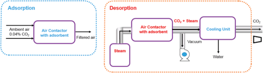
Like liquid solvent systems, solid sorbent direct air capture systems have two main processes: adsorption and desorption that operate cyclically (Figure 5.4). In these systems, air is blown through a solid adsorbent contained within an air contactor, where the CO2 in the air is adsorbed onto the solid adsorbent. Next, the solid adsorbent with CO2 is exposed to heat and/or vacuum to liberate the CO2 from the solid adsorbent. Finally, the solid sorbent is cooled before it is restarted.
Owing to the suitability of temperature swing adsorption (TSA) for capturing ultra-dilute species (Lively and Realff, 2016), the committee assessed a generic adsorption process employing either just TSA or TSA in combination with vacuum swing adsorption (VSA) to place probable bounds on energy consumption, CO2 emissions, and associated costs for solid sorbent systems.10 This section describes a generic, hypothetical process, as well as its estimated energy use and consequent CO2 emissions.
___________________
10 Such a process does not map to the humidity swing approach employed by Infinitree, as outlined in Table 5.1.
Unit Operations
Adsorption
Air is blown through a solid structure (contactor) that contains a suitable CO2-adsorbing material and CO2-depleted air is emitted from the process. In the adsorber, the main contributor to energy use is the electrical energy required for fans to drive air through the contactor containing the solid sorbent. The primary driver for the energy consumption associated with this step is the pressure drop through contactor. This part of the process deviates substantially from the more often studied flue gas separations.
Desorption
After the solid sorbent has been saturated with CO2, it is moved to the desorber11 where heat (TSA) or heat and vacuum (TSA/VSA) systems are used to desorb CO2 (regeneration) and produce a concentrated CO2 stream. Regeneration is the most energy-intensive step for a solid sorbent direct air capture system and includes the thermal energy needed to induce CO2 desorption (ΔHads) and heat up the sorbent, contactor and other equipment (ΔHsens), as well as electrical energy needed for vacuum pumps (if employed). Energy consumption in the condenser is deemed negligible, although some heat could be recovered if integrated into steam generation, and is therefore not considered in this analysis. Overall, the energetics for this energy-intensive step of the process are the same as for a similar regeneration step in a process targeting a more concentrated feed (e.g., capture from flue gas). Because of the energy intensity, process design innovations for this desorption step can have a large impact on the overall process efficiency. Designs that give rapid heat transfer, as well as minimize the CO2 partial pressure over the adsorption media, are advantageous, providing both concentration and thermal driving forces for CO2 desorption.
Mass and Energy Balance
In general, solid sorbent system designs aim to (1) minimize pressure drop for flow through the air-sorbent contactor; (2) minimize contactor mass while maximizing sorbent mass (thus minimizing the sensible heat energy losses); (3) maximize the CO2
___________________
11 Or the adsorber is switched into desorption mode, if a single unit is deployed.
uptake; and (4) advantageously manage the water uptake.12 For the generic process considered here, key process parameters were varied within a physically realistic range (Table 5.5). Adapting Realff and Kawajiri’s methodology (Sinha et al., 2017), the committee estimated individual contributors to the energy consumed in the process and the cost of CO2 capture.
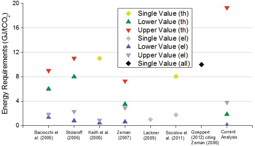
Estimated process energy intensities for the generic solid sorbent direct air capture system were obtained by varying each parameter within the range provided in Table 5.6. The calculated thermal and electrical energy requirements are reported in Table 5.7, with the associated CO2 emissions if the energy were provided by coal, natural gas, nuclear, wind, or solar reported in Table 5.8 (NREL, 2013). The electrical energy consumption was costed at an average grid price ($0.06/kWh) and the thermal energy cost was derived by considering the extra steam that would have to be produced to replace the electrical energy delivered from the condensing turbine of a power plant (Sinha et al., 2017). The estimated energy consumption falls in a similar range reported for other processes in the literature (Figure 5.5, Broehm et al., 2015).
Because of the possibility for wide variation in parameters, the committee considered five scenarios that represent different degrees of process optimization and performance (i.e., best case, low, mid, high, and worst case). The combination of every best-case parameter results in the lower bound (1-best), a scenario that may be unachievable because of correlations among various parameters, where optimizing one may move another away from an optimum (using currently known materials and approaches). Similarly, there are many ways to design a poor process with very high energy consumption. This scenario (5-worst) is presented here as an example where all the most pessimistic values were used. These two cases are shown for completeness, although the committee does not expect practical operation at either extreme. More realistically, three estimates using parameters in the middle of the range are provided (2-low, 3-mid, 4-high), where the descriptive words refer to anticipated carbon emissions and energy consumption. The approach used for these calculations is described in Appendix H, along with the specific parameters for each case.
An advantage of many recent solid sorbent–based direct air capture processes is that they do not require high temperature thermal energy. In an ideal scenario, the electrical energy needs should be met with renewable energy, and the thermal energy
___________________
12 For many sorbents, water uptake should be minimized to minimize the amount of water that must desorbed from the sorbent in each cycle, and its associated energy penalty. However, some adsorbents may benefit from co-adsorbing water, because CO2 uptake may increase, in which case water uptake must be managed advantageously. Water adsorption can also be managed to balance the production of fresh water as a coproduct.
used should be acquired from low temperature waste heat when such heat sources are suitable and available. Doing so helps to maximize net CO2 removal. Furthermore, use of waste heat could provide important stepping stones for early installations to operate with more privileged economics, potentially offsetting the disadvantage of being early on the technology learning curve. Nonetheless, because deployment that impacts negative emissions on a global scale will require heat and power, in all scenarios considered in this chapter, the energy used is sourced exclusively for the direct air capture process, and no assumption of waste heat use is made.
For each step in the solid sorbent direct air capture process, the CO2 emissions were evaluated under several scenarios, including providing the electrical energy from wind, solar thermal, nuclear, natural gas, or coal and thermal energy from solar thermal, nuclear, coal, or natural gas (Table 5.7). The calculated energy requirements suggest
TABLE 5.6 Model Parameters That Affect Estimated Performance of a Solid Sorbent Direct Air Capture Process
| Parameter | Units | Range |
|---|---|---|
| Inputs | ||
| Contactor to adsorbent ratio | kg/kg | 0.10-4.0 |
| Adsorbent purchase cost | $/kg | 15-100 |
| Adsorbent lifetime | y | 0.25-5.0 |
| Sorbent total capacity (at 400 ppm) | mol/kg | 0.5-1.5 |
| Desorption swing capacitya | mol/mol | 0.75-0.90 |
| Air velocity | m/s | 1-5 |
| Desorption pressure (VSA) | bar | 0.2-1.0 |
| Desorption final temperature (TSA) | K | 340-373 |
| Heat of adsorption (CO2) | kJ/mol | 40-90 |
| Outputs | ||
| Adsorption time | min | 8-50 |
| Desorption time | min | 7-35 |
| Mass transfer coefficientb | 1/s | 0.01-0.1 |
| Pressure drop | Pa | 300-1,400 |
aFraction of CO2 adsorbed that is desorbed and recovered as product.
bLumped linear driving force coefficient accounting for all resistances, see Appendix D.
NOTE: Some parameters (inputs) were varied within a physically realistic range, based on literature reports, and outputs were calculated from the model.
TABLE 5.7 Estimated Unit Operation Energy Requirements for Solid Sorbent Direct Air Capture Systems
| Step | Type | Energy Required (GJ/t CO2) | |
|---|---|---|---|
| Mid-Range (low-high, 2-4) | Full-Range (best-worst, 1-5) | ||
| Desorption heat (100°C sat. steam) | Thermal | 3.4-4.8 | 1.85-19.3 |
| Air contactor fans | Electrical | 0.55-1.12 | 0.08-3.79 |
| Desorption vacuum pump | Electrical | (110-140) x 10-4 | (4–910) x 10-4 |
| Total | 3.95-5.92 | 1.93-23.09 | |
Like liquid solvent systems, solid sorbent systems have a minimum work rate of 0.45 GJ/tCO2 to capture 60-75 percent CO2 from air to a 99 percent pure CO2 stream. Based on the energy requirements outlined for solid sorbent systems, the “real” work rate is 1.9-23.1 GJ/tCO2, leading to an exergy efficiency range of 2-24 percent, with the middle-range scenarios (2-low to 4-high) being 7.6-11.4 percent.
that the worst-case scenario (5-worst) would be unable to provide negative emissions under any scenario where fossil energy was used, even those that use renewable energy for electricity, because of the extensive thermal energy requirements provided by fossil energy. However, even the worst-case scenario that provided negative emissions uses solar thermal or nuclear energy for operation. By contrast, most other scenarios are substantially carbon negative, with the more realistic estimates (2-low to 4-high) being negative even when coal was used to provide all the energy (0.47-0.74 Mt CO2 emitted per Mt CO2 captured). While the use of coal to power a solid sorbent direct air capture system is not likely, it provides a useful worst-case emissions scenario, providing an upper bound to the problem. In the near term, one could envision rapid deployment using natural gas to provide thermal energy. Such a scenario yields a process with acceptable negative emissions (0.29-0.44 Mt CO2 emitted per Mt CO2 captured). Negative emissions drop further when renewable electricity is used (Table 5.7) and further still when thermal energy is generated from renewable sources. Nuclear energy provides another low emissions option.
Process Economics
As noted above, the cost estimates presented here are for the separation and capture of CO2 from ambient air from modestly optimized, generic direct air capture systems operating at 65-75 percent capture with highly concentrated CO2 product (~99 percent purity). These cost estimates reflect the total annual economic penalty incurred for removing 1 Mt CO2 from air on a per ton CO2 captured basis. Because additional CO2 emissions can be generated in several of the steps required in direct air capture systems, the net costs of CO2 removed are also presented. The cost estimates presented vary by energy source and do not account for compression, transportation, injection, and sequestration (see Chapter 7 on geologic sequestration). The estimated costs of CO2 capture for the range of scenarios considered are provided in Tables 5.9 and 5.10.
The two main phases of the cyclic adsorption process are shown above in Figure 5.4. In the adsorption phase, air is contacted with a solid structure that contains a suitable CO2-adsorbing material, with air depleted in CO2 being the exit stream from the process. In this step, key contributors to the process cost include (1) the energy required to pass the air over or through the adsorbing material, (2) the cost of the adsorbent, and (3) the cost of the contactor and other equipment, such as the fans that provide airflow. For routine equipment, such as the blowers and vacuum pumps, a factor of 4 was applied to the purchase cost to represent the total installed cost. For more innovative components, such as the gas-solid contactor, a factor of 6 was applied. It is instructive to compare the capital cost for the air-sorbent contactor between the solvent and solid sorbent cases. For the former, the total capital cost for the contactor ranges from $210 million to $420 million. For the latter, the total cost ranges from $13 million to $84 million. Considering that the solid sorbent case has a 10-fold higher surface area per volume, the order of magnitude of these costs is similar.
In the desorption phase of the process, heat (TSA) or heat and vacuum (TSA/VSA) are applied to the system to induce CO2 desorption and recover a concentrated product. This second step incurs substantially more operating costs, including costs associated with the energy needed to induce desorption (ΔHads), energy required to heat the sorbent, contactor, and other equipment (ΔHsens), and energy necessary to operate the vacuum pump, if such a pump is employed. Among capital costs, the costs of the pump and condenser are assigned to this step, whereas other costs are assigned to the first step. Adapting the methodology described by Realff and Kawajiri (Sinha et al., 2017), the committee estimated the individual contributors to the cost of CO2 capture for different parameter sets.
TABLE 5.8 Estimated CO2 Emissions Generated by a Solid Sorbent Direct Air Capture System That Removes 1 Mt/y CO2 Depending on Energy Source
| Step | Energy Source | Carbon Emissions (Mt/y CO2) | |
|---|---|---|---|
| Mid-Range (low-high, 2-4) | Full-Range (best-worst, 1-5) | ||
| Desorption heat | Solar | 0.008-0.01 | 0.004-0.04 |
| Nuclear | 0.004-0.005 | 0.002-0.02 | |
| Natural gas | 0.22-0.30 | 0.12-1.2 | |
| Coal | 0.32-0.44 | 0.17-1.7 | |
| Air contactor fans | Solar | 0.0004-0.008 | 0.0005-0.026 |
| Wind | 0.002-0.003 | 0.0002-0.012 | |
| Nuclear | 0.002-0.004 | 0.0002-0.013 | |
| Natural gas | 0.07-0.14 | 0.01-0.47 | |
| Coal | 0.15-0.3 | 0.019-1 | |
| Vacuum pump | Solar | (0.93-1.9) x 10-6 | (0.0015-2.8) x 10-5 |
| Wind | (0.47-0.7) x 10-6 | (0.0059-13) x 10-6 | |
| Nuclear | (0.47-0.93) x 10-6 | (0.0059-14) x 10-6 | |
| Natural Gas | (1.6-3.3) x 10-5 | (0.029-50) x 10-5 | |
| Coal | (0.35-0.7) x 10-4 | (0.0056-10.8) x 10-4 | |
| Total | Solar/solar | 0.0084-0.018 | 0.0045-0.066 |
| Nuclear/nuclear | 0.006-0.009 | 0.0022-0.032 | |
| Solar/natural gas | 0.22-0.30 | 0.12-1.2 | |
| Wind/natural gas | 0.22-0.30 | 0.12-1.2 | |
| Natural gas/natural gas | 0.29-0.44 | 0.13-1.67 | |
| Coal/coal | 0.47-0.74 | 0.19-2.7 | |
Note: Emission factors for different energy sources are referenced near the start of this chapter (NREL, 2013).
For a generic solid sorbent system, with all parameters varied within the ranges listed in Table 5.5, the committee calculated carbon capture costs ranging from $18/tCO2 to over $1,000/t CO2. The combination of every best-case parameter resulted in the lower bound (1-best), a scenario that is likely unachievable due to correlations among various parameters, where optimizing one may move another away from an optimum (using currently known materials and approaches). There are many ways to design a poor process with costs that exceed $1,000/tCO2, with the calculated upper bound in this parameter space designated as the worst case (5-worst). As noted above, three other, more realistic scenarios were also considered (2-low, 3-mid, 4-high). A description of the approach used for the calculations is provided in Appendix D, and the specific parameter used in each case are provided in Table 5.9. A sensitivity analysis of the impact of the various parameters is provided in Table 5.10. All five scenarios are shown, making it clear that the adsorbent CAPEX dominates the overall cost. In comparison, no other capital and operating costs are substantial cost drivers. This demonstrates the importance of adsorbent cost and lifetime, as well as the potential for adsorbent material innovations to further reduce costs.
As noted above, the cost estimates span a wide range. Disregarding the lower bound as not realistically achievable and the upper bound as prohibitively expensive, the middle range of scenarios is perhaps most instructive. These estimates yielded capture
costs of $88-228/t CO2 for a generic solid sorbent direct air capture system. It is plausible that these costs could be reached within the next decade, considering that Climeworks has reported a capture cost of about $600/tCO2 for its first generation commercial plant. From this point, costs should decline as process design and process operation improve, falling into the range calculated above.
This analysis of solid sorbent direct air capture systems reveals the following observations. First, processes that are not specifically optimized for direct air capture will generate costs that fall within the range estimated by House et al. (≥ $1,000/tCO2, 2011). Second, direct air capture processes that employ physically realistic process parameters designed for direct air capture systems can generate costs in the range of $100-600/tCO2. Third, large-scale processes (over 1 Mt/y CO2) employing known materials and gas-solid contactors in the most promising scenarios could generate costs close to $100/tCO2, though no such large-scale, continuously operating installation exists at this time.
Summary of Analysis of Solvent and Solid Sorbent Direct Air Capture Systems
Table 5.11 presents the estimated energy required for direct air capture, along with the CO2 footprint and net CO2 removal assuming a plant designed to capture 1 Mt/y CO2. Both liquid solvent and solid sorbent cases have been considered, with scenarios that vary to meet the electric and thermal needs of the direct air capture plant.
TABLE 5.9 Input Parameters Used for Cost Estimates for the Generic Solid Sorbent Direct Air Capture System, with Selected Outputs
| Parameters | 1-Best | 2-Low | 3-Mid | 4-High | 5-Worst |
|---|---|---|---|---|---|
| Adsorbent purchase cost ($/kg) | 15 | 50 | 50 | 50 | 100 |
| Adsorbent life (y) | 5 | 0.5 | 0.5 | 0.5 | 0.25 |
| Sorbent total capacity (mol/kg) | 1.5 | 1.0 | 1.0 | 1.0 | 0.5 |
| Desorption swing capacity (mol/mol) | 0.90 | 0.8 | 0.8 | 0.8 | 0.75 |
| Contactor to adsorbent ratio (kg/kg) | 0.1 | 0.1 | 0.2 | 1.0 | 4.0 |
| Desorption pressure (bar) | 0.2 | 0.5 | 0.5 | 0.5 | 1.0 |
| Outputs | |||||
| Final desorption temperature (K) | 340 | 360 | 360 | 360 | 373 |
| Cycle time (min) | 39 | 16 | 28 | 42 | 26 |
TABLE 5.10 Estimated Annualized Capital (CAPEX) and Operating (OPEX) Costs for a Generic Solid Sorbent Direct Air Capture System with a Capacity of 1 Mt/y CO2 Removal
| Parameters | 1-Best | 2-Low | 3-Mid | 4-High | 5-Worst |
|---|---|---|---|---|---|
| Adsorbent CAPEX | 3.6 | 70 | 122 | 186 | 988 |
| Adsorption OPEX | 1.3 | 9 | 12 | 19 | 4.3 |
| Blower CAPEX | 3.6 | 2.1 | 3.7 | 6.7 | 13.7 |
| Vacuum pump CAPEX | 4.5 | 2.6 | 4.7 | 8.5 | 17.4 |
| Steam OPEX | 2.5 | 2.2 | 2.4 | 3 | 43 |
| Condenser CAPEX | 0.03 | 0.07 | 0.075 | 0.1 | 0.4 |
| Contactor CAPEX | 2.2 | 1.3 | 2.3 | 4.1 | 8.4 |
| Vacuum pump OPEX | 0.3 | 0.2 | 0.2 | 0.24 | 0.3 |
Energy Requirements
The thermal component of the energy required to operate a direct air capture plant dominates the electric component because of the need for strong CO2-binding chemistry. The electricity required is used to operate fans and pumps and can be minimized through the design of a shallow contactor to minimize pressure drop through the system. The strong-binding chemistry is necessary to produce high-purity CO2 from dilute CO2 in the air, that is, approximately 400 ppm. The thermal requirement for regeneration of the material used for capture may be satisfied by burning natural gas directly, with the generated heat used for regeneration directly or indirectly through the production of steam. Another option for meeting the thermal requirement is H2 combustion, which results in zero CO2 emissions. It is clear from Table 5.10 that the thermal requirement for the liquid solvent system13 is significantly larger than that for the solid sorbent system. This is because the liquid solvent approach involves heating CaCO3 up to 900°C to produce high-purity CO2, while the temperature required for solid sorbent regeneration is much lower at approximately 100°C. The table presents a range of energy estimates for the solid sorbent–based approach.
The electric requirement is similar regardless of the approach. For the solvent-based approach, H2 combustion was also considered, with H2 produced through electrolysis. If using the grid mix of electricity, this approach increases that component
___________________
13 Solvent systems are not inherently disadvantaged compared to solid sorbent systems, and both can operate in high- or low-temperature regimes if the sorption/desorption chemistry is designed to do so.
TABLE 5.11 Summary of Estimated Energy Requirements, CO2 Footprint, and Carbon Capture for 1 Mt/y CO2 Liquid Solvent and Solid Sorbent Direct Air Capture Systems
| Direct Air Capture System | Energy Source | Energy Required (GJ/t CO2) | CO2 Generated (Mt/y CO2) | Net CO2 Avoided | Capture Cost ($/t CO2) | ||||
|---|---|---|---|---|---|---|---|---|---|
| Electric | Thermal | Electric | Thermal | Electric | Thermal | (Mt/y CO2) | Captured | Net Removeda | |
| Liquid Solvent | NG | NG | 0.74-1.7 | 7.7-10.7 | 0.11-0.23 | 0.47-0.66 | 0.11-0.42 | 147-264 | 199-357 |
| coal | NG | 0.74-1.7 | 7.7-10.7 | 0.18-0.38 | 0.47-0.66 | 0-0.35 | 147-264 | 233-419 | |
| wind | NG | 0.74-1.7 | 7.7-10.7 | 0.004-0.009 | 0.47-0.66 | 0.34-0.53 | 141-265 | 156-293 | |
| solar | NG | 0.74-1.7 | 7.7-10.7 | 0.01-0.03 | 0.47-0.66 | 0.31-0.52 | 145-265 | 165-294 | |
| nuclear | NG | 0.74-1.7 | 7.7-10.7 | 0.01-0.02 | 0.47-0.66 | 0.32-0.52 | 154-279 | 173-310 | |
| solar | H2b | 11.6-19.8 | 7.7-10.7 | 0.01-0.03 | 0 | 0.99 | 317-501 | 320-506 | |
| Solid Sorbentc | solar | solar | 0.55-1.1 | 3.4-4.8 | 0.0004-0.008 | 0.008-0.01 | 0.892-0.992 | 88-228 | 89-256 |
| nuclear | nuclear | 0.55-1.1 | 3.4-4.8 | 0.002-0.004 | 0.004-0.005 | 0.91-0.994 | 88-228 | 89-250 | |
| solar | NG | 0.55-1.1 | 3.4-4.8 | 0.0004-0.008 | 0.22-0.30 | 0.70-0.78 | 88-228 | 113-326 | |
| wind | NG | 0.55-1.1 | 3.4-4.8 | 0.002-0.003 | 0.22-0.30 | 0.70-0.78 | 88-228 | 113-326 | |
| NG | NG | 0.55-1.1 | 3.4-4.8 | 0.07-0.14 | 0.22-0.30 | 0.56-0.71 | 88-228 | 124-407 | |
| coal | coal | 0.55-1.1 | 3.4-4.8 | 0.15-0.3 | 0.32-0.44 | 0.26-0.53 | 88-228 | 166-877 | |
a Assuming the use of an oxy-fired kiln to provide heat from natural gas in the calcination process, leading to greater CO2 production and hence lower cost of net CO2 removal, using a basis of 1.3 Mt CO2 for NG/NG, 1.2 Mt CO2 for coal/NG. (NG = natural gas).
b Assuming all hydrogen is produced via electrolysis using near zero-carbon power.
c Scenarios range from 2-low to 4-high.
significantly; however, the electricity could be sourced from carbon-free nuclear, wind, or solar, which would maximize the impact of this pathway to direct air capture.
Carbon Footprint
If the electricity or thermal energy requirements are met using fossil fuels, then significant CO2 emissions will result, thereby reducing the effect of a direct air capture plant in terms of CO2 removal from the air. The committee assumed a grid mix, carbon-free paths such as nuclear, wind, and solar thermal, and fossil-intensive paths such as coal and natural gas. The CO2 emitted from meeting the energy requirements increases as expected—from nuclear, wind, or solar thermal, to natural gas, and finally to coal as the source with the greatest CO2 emissions. Because the solvent-based approach regenerates CaCO3 in an oxy-fired kiln, it can easily capture the CO2 generated from burning natural gas to meet the thermal requirements in addition to maximizing the removal of CO2 from the air (Keith et al., 2018). In fact, on average, an additional 0.5 Mt/y CO is produced and captured along with the CO2 from air by condensing the exhaust mixture of CO2 and water vapor. In principle, any process can employ fossil energy with carbon capture from the energy emissions to reduce its carbon footprint, although at additional capital and operating costs. Such a scenario was considered here for the solvent case because it is an inherent part of the Carbon Engineering design.
Carbon Removal Cost
If fossil-based energy resources are used to provide the energy requirements of a direct air capture system, then an accurate estimate of the cost to removing CO2 from the air requires consideration of the net CO2 removed because burning fossil fuels produces CO2. On average, the costs for net CO2 removed for the solid sorbent–based approach range from $89 to $877/tCO2, depending on the adsorption scenario, while the costs range for the solvent-based approach range from $156 to $506/tCO2, depending on the use of natural gas or renewable H2 for the thermal source.
IMPACT POTENTIAL
The potential for direct air capture flux and capacity has no fundamental physical limit, making its primary limitation financial. The potential impact is limited by the investment required to scale direct air capture as well as the availability of geologic
storage to sequester the captured CO2. Available pore space must be shared with the CO2 produced from conventional carbon capture efforts in addition to BECCS. The mainstream literature has often stated that an advantage of a direct air capture plant is that “it can be placed anywhere.” Although direct air capture can be deployed in many locations where BECCS cannot—because it does not require arable land and therefore may have greater access to remote pore volumes—this assessment should be approached with caution. Deployment of direct air capture on any significant scale (i.e., thousands of tons CO2 removed per year) requires significant infrastructure, energy, and land. At 1 Gt/y CO2 removal and $100/t CO2 for combined separation, transport, and reliable sequestration, the total investment would be about $100 billion per year or 0.5 percent of U.S. gross domestic product (GDP). At a global scale of 5 Gt/y CO2 removal and $100/t CO2, the total investment increases to about $500 billion or 0.6 percent of global GDP. Achieving this rate and scale of CO2 removal will require substantial investments in fundamental research, demonstration, and deployment.
To maximize the net emissions removed from the air and the ultimate impact of direct air capture and sequestration, the use of renewable energy resources should be maximized where possible. The integration of renewable energy with base load natural gas, or use of combined heat and power units, could be a cost-effective approach to scaling up direct air capture and sequestration.
SECONDARY IMPACTS
Land
Direct air capture systems have significantly fewer land requirements than do afforestation/reforestation and BECCS approaches, and because they do not require arable land their impacts on biodiversity would be much smaller. Consider the Amazon rainforest as an example. The net primary production of the Amazon is approximately 270 km2 per Mt/y CO2. With a land area of 5.5 million km2, this equates to an annual CO2 removal of about 20 Gt CO2. As discussed later in this section, the land area requirement for the equivalent CO2 removal using direct air capture is roughly 40 times smaller at 7 km2 per Mt CO2 if powered by natural gas. If you consider a temperate deciduous forest with a net primary production of 390 km2 per Mt/y CO2 and an average tree density of 200 per acre, a single tree acts to remove (net), on average, 50 kg CO2/y; in this sense, a 1 Mt CO2 direct air capture system does the work of 20 million tree equivalents, or a forest spanning 100,000 acres.
In general, the land that is required for direct air capture is impacted by the size of the
contactor and the spacing requirements of multiple contactors and contactor configuration. The land area estimates discussed in this section are those required to capture 1 Mt/y CO2 at 65-75 percent capture.
Liquid Solvent Systems: In the contactor design of Keith and Holmes, the cross-sectional inlet area is oriented normal to the land surface. This use of vertical space minimizes direct land use per contactor structure. For example, a 4,000 m2 inlet area is achieved through a structure containing packing dimensions of 20 m high by 200 m long by 8 m wide. These packing dimensions are a result of a full structural engineering analysis and cost optimization that examined sensitivity to height and width (Holmes and Keith, 2012). If the packing material is housed in a shell structure that is 110 percent of the packing dimensions, then the direct land use is roughly 2,000 m2 per contactor, or half the inlet cross-sectional area. At 400 ppm CO2 in air and 100 percent capture efficiency, the capture of 1 t/y CO2 from air corresponds to an air volumetric flow rate = 4.09 × 10⁻² m3/s. Assuming an air inlet velocity = 1.5 m/s and CO2 capture efficiency = 75 percent, an air contactor cross-sectional area = 38,000 m2 is obtained from:
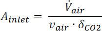
At the optimized conditions considered in this study (75 percent capture and V = 1.5 m/s), a cross-sectional area of roughly 38,000 m2 is required to capture 1 Mt/y CO2 or the equivalent of 10 air contactor units with packing dimension of 20 m × 200 m × 8 m per unit.
The array of multiple contactors needs to be arranged around a centralized regeneration facility and should be positioned to minimize piping and other associated infrastructure costs. An important consideration in contactor arrangement involves the region where CO2-depleted air exits the contactor. To maximize separation efficiency, this region should not feed into the intake of an adjacent contactor. Rather, appropriate spacing is required for proper tropospheric mixing to occur such that air entering an adjacent contactor has fully equilibrated to ambient conditions (400 ppm CO2) (Figure 5.6). A centralized regeneration facility including the causticizer, slaker, calciner, air separation unit, and other auxiliary equipment is expected to have a direct land impact of approximately 20 percent that of the air contactor array (Keith et al., 2018). When multiple contactors are positioned to minimize piping and other infrastructure costs, the direct land required is approximately 24,000 m2 (~6 acres) including the regeneration facility (Keith et al., 2018). Indirect land use accounts for the spacing between contactors if multiple direct air capture plants are to be constructed in a
single area. In a single-plant design, although there would be no adjacent plant, the region of tropospheric mixing may pose risks not yet well understood because of the lower local concentration of CO2. For example, plants of the C3 photosynthetic genotype (80-95 percent of all species) grown under glacial conditions (CO2 < 200 ppm) are known to suffer from compromised survival and limited reproduction. Further, these conditions may affect plant tolerance to drought, heat, and other stressors, an important consideration if direct air capture siting includes arable land (Sage and Cowling, 1999; Ward, 2005). To avoid unwanted consequences or potential trophic cascades related to this CO2-depleted region, this land area is assigned as indirect land use regardless of a single or multiple plant design. When indirect land use is considered, the total land requirement jumps by about 300 times to 7 km2 (~1,730 acres).
The land area discussed does not consider an onsite power island. The average size of a natural gas plant in the United States is 30 acres, or 1,400 m2/MW (Stevens et al., 2017). Indirect land use associated with resource production, but excluding transmission and transportation, increases the land requirement to approximately 8100 m2/ MW, or 2.4 km2 for a power requirement of 300 MW. Additional land may be required if onsite renewable energy (e.g., PV solar panels or concentrated solar thermal) is used to offset any portion of the electric and thermal requirements. The National Renewable Energy Laboratory reports a generation-weighted14 total land use of 3.0 acres GWh-1 yr-1 for concentrated solar thermal, and 5.5 acres GWh-1 yr-1 for small two-axis flat panel PV power plants (Ong et al., 2013). If solar is used to offset 25 percent of the electric and thermal requirements, an additional 3,600 acres of total land area is required. In the theoretical limit where solar power and the Conservation Stewardship Program (CSP) are used to offset all electric and thermal requirements, total land use escalates to 14,500 acres, or roughly 58.6 km2. One-hundred such facilities (representing 100 Mt CO2 removal per year) would require a land area roughly the size of Delaware.
The National Renewable Energy Laboratory also reports land-use data for wind generation. Here, because of the wide range of wind configurations and absence of a universally accepted metric for land use in wind plants, the average total land area is 40±25 acres GWh-1 yr-1. Although this requirement is larger than for solar, a key advantage of wind power is the ability to use the land between turbines, because the turbine footprint is less than 10 percent of the directly impacted land area. Direct land
___________________
14 Total land area requirements vary due to location, array configuration, derate factor, and tracking technology, and range from 2 to 7 acres/GWh/y for small two-axis PV, and from 2 to 8 acres/GWh/y for concentrated solar power.
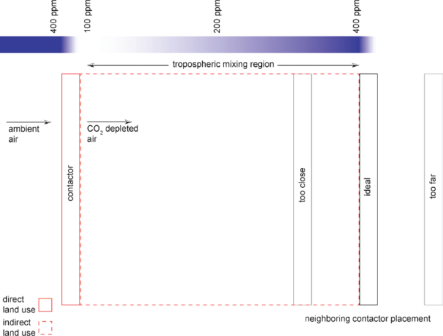
use may be avoided altogether through contracts with off-shore wind farms, which typically experience higher capacity factors than their land-based counterparts.
An alternative configuration for sorbent-based direct air capture involves onsite electrolysis of H2 using solar power. The electric demand here ranges from 400 to 500+ MW for a 1 MtCO2 removal plant. Using the generation-weighted average land intensity for solar-PV power production quoted above, the land footprint for this configuration is 19,250-25,500 acres, or roughly 80 to 100 km2.
An important consideration in these land area calculations pertains to the inter-contactor spacing depicted in Figure 5.6. The direct land use of a configuration, including the contactor array and regeneration equipment, but excluding land for power, is 0.3 percent of the total land footprint. Thus, a direct air capture operator
might decide to use the indirect land space to house—in part—on-site power infrastructure, assuming the presence of such equipment has a negligible impact on the equilibration of contactor outgas to ambient levels (400 ppm). For example, this space may be suitable for the installation of low-lying solar panels, whereas wind turbines could potentially reduce wind speed, which would impact the rate of tropospheric air mixing and potentially the velocity of air entering an adjacent contactor. For optimal land use, the impact of different land uses on overall direct air capture plant performance must be well understood.
Solid Sorbent Systems: Similar contactor spacing constraints exist as discussed above for the solvent case. Today, companies developing commercial direct air capture technologies are targeting designs that remove CO2 from the air at areal intensities of ~2-200 kt/y-acre CO2 depending on the technology. This footprint accounts for the land area for process equipment, areal mixing, and safety margins, with the air/solid contacting equipment covering only a small fraction of the total plant area, typically less than 5 percent. For the hypothetical adsorption direct air capture process considered above, a single direct air capture plant would capture ~200-1,370 kg CO2/m2-y.15 To capture 1 Mt/y CO2, given the capture rates mentioned above, numerous such units would typically be deployed (i.e., scaling out, rather than scaling up). Given the range of capture rates, 200-1,250 acres of land are required for 1 Mt/y CO2, with the middle three scenarios (2-low to 4-high) requiring 300-425 acres. These areal requirements consider only the direct air capture plant. To also account for local power generation, the land requirements increase to 550-800 acres for natural gas–based thermal and electrical energy, or 1,355-,2450 acres for natural gas–based thermal energy and solar–based electrical energy, assuming no space in the direct air capture plant footprint can accommodate power generation equipment.
Water
Water loss in direct air capture primarily occurs during the sorbent-air contacting process. In both the proposed solid and solution-based direct air capture processes, most water use is contained in closed-loop systems, whereby water is continuously recycled. Nonetheless, nearly all processes have the potential for water loss, and this parameter should be carefully considered when any new process is developed.
Liquid Solvent Systems: Water loss in the contactor is mainly due to evaporation, with a trivial contribution from drift loss. As outlined in the Section on Energetics and
___________________
15 This is the range spanned by the five scenarios, from 1-best to 5-worst.
Carbon Footprint, 8.2 Mt of make-up water should be supplemented to offset this loss each year. This value is calculated at 65 percent humidity, 16, 2M KOH(aq) solution and may increase if the direct air capture plant is placed in more arid conditions. Stolaroff et al. (2008) show that if the relative humidity is reduced to 50 percent, the evaporative water loss increases from 20 mol H2O/mol CO2 to 80 mol H2O/mol CO2, a four-fold increase. Higher molarity solutions have a lower vapor pressure and experience lower evaporative losses. The direct air capture operator may choose to mitigate water loss through the adjustment of solvent molarity based on ambient conditions. “Drift” loss is a phenomenon described by the cooling industry as the escape of droplets from the contactor as a result of the cross-flow configuration. Keith et al. (2018) describe measurements that indicate that airborne KOH concentrations less than 0.6 mg/m3 air flow out of the contactor, which is below the National Institute for Occupational Safety and Health upper exposure limit of 2.0 mg/m3. Demonstration-scale projects should conduct further measurements of this kind to minimize the risk associated with the configuration choice.
Cooling water is required to condense out water vapor from the calcination flue gas. At a flue gas output of roughly 640 ft3/min, roughly 1,300L/min of water is required. This water is largely recirculated and does not contribute significantly to the overall water consumption.
In the oxy-firing process, combustion water and CO2 are produced through natural gas combustion in an oxygen-enriched environment. According to Keith et al. (2018), a water “knock-out” stage occurs before CO2 compression. This water is combined with a make-up feed of 531 t/h in a settling tank, to be subsequently mixed with CaO to produced calcium hydroxide for the contactor.
The majority of process waste consists of Ca-based solids that precipitate out of the sorbent cycle because of contaminants that enter via the contactor. The generic solvent process does not produce a significant amount of wastewater, and onsite wastewater treatment is not anticipated.
Solid Sorbent Systems: Direct air capture companies currently employ processes that vary widely in terms of freshwater usage. The hypothetical adsorption-based direct air capture process analyzed here, which relies on T/VSA using saturated steam condensation on the adsorbent and contactor as the mode of heat transfer, can result in water loss to the environment. For those who employ this approach, such as Global Thermostat, the potential water loss is usually accepted as a consequence of the improved heat transfer and overall process performance offered by this mode of heat transfer. In an alternate approach, sorbent regeneration can be accomplished by indirect heat transfer such that steam is contained in a fully closed system, allowing for negligible
water losses in some cases. It has been reported that under some operating conditions, solid sorbent–based processes produce fresh water, which is harvested from the air concurrently with the CO2 capture.
In a typical configuration of the hypothetical adsorption-based direct air capture process, water loss would amount to ~1.6 MtH2O/y for capture of 1 Mt/y CO2 (about 4 moles of water lost per moles of CO2 captured). This value could vary significantly depending on the ambient humidity at the capture site, and as noted above, in some scenarios fresh water can actually be produced. Water loss would be expected to be larger in drier climates and smaller in humid climates. In addition, water is required for the synthesis of the solid sorbents, and considering the short sorbent lifetimes, water consumption for this purpose could be substantial.
At least one company, Infinitree, is developing a solid sorbent–based technology that deploys an entirely different capture approach. Rather than a T/VSA process and solid amine-based adsorbents, this technology would deploy quaternary ammonium-based sorbents that use a swing in humidity to induce CO2 adsorption and desorption. With this approach, which differs substantially from the hypothetical process outlined in this chapter, CO2 is captured under dry conditions and then desorbed and concentrated under humid conditions.
In the academic literature, water loss from hypothetical direct air capture processes has thus far received marginal attention relative to other factors such as energy use. Future R&D efforts should carefully consider water production/use.
Environmental
One potential environmental impact of direct air capture processes is the depletion of CO2 from the air exiting the contactor. Many studies have examined the environmental impact of elevated atmospheric CO2, but few studies have examined the impact of lowered CO2 levels. De Marchin et al. demonstrated that reduced CO2 leads to lower photosystem II (PSII) photochemical efficiency in algae cultures (de Marchin et al., 2015). This region of local CO2 depletion could have adverse effects on crop efficiency and the overall health of local habitats. Thus, direct air capture siting should consider the nature and role of regions directly “downwind” of large CO2-scrubbing contactors.
Liquid Solvent Systems: The generic solvent-based direct air capture process involves two chemical-intensive processes: (1) contact of ambient CO2 in a caustic KOH(aq) solution and (2) regeneration of KOH through a Ca-based causticization and chemical swing cycle. Both of these processes are mature, well studied, and long employed
in industry: KOH(aq) is used to scrub CO2 as a pre-stage in cryogenic air separation (Holmes and Keith, 2012), and the Ca-based recovery cycle is based on the Kraft process used by the pulp and paper industry (Baciocchi et al., 2006). Wastewater is not generated in significant amounts in this process, and solid waste buildup in the recovery cycle should have similar environmental implications and disposal guidelines as the reclaimer waste in a traditional monoethanolamine (MEA)-scrubbing operation.
Solid Sorbent Systems: For the generic adsorption-based direct air capture process, chemicals are primarily released from the active CO2 adsorbing materials, which are intermittently exposed to the ambient air. Most existing companies employ amine-based solid adsorbents, which are not indefinitely stable under aerobic conditions. Studies of volatile organic carbon emissions from conventional carbon capture plants employing liquid amine solutions as capture agents suggest that amine-based sorbents can break down over time into species, such as ammonia, nitrosamines, and other nitrogen-containing compounds, that may damage organisms or the environment (Azzi et al., 2014; de Koeijer et al., 2013; Karl et al., 2011, 2014; Ravnum et al., 2014; Zhang et al., 2014). Little is known about emissions from solid amine-based adsorbents, which is an area where research could clarify the potential emissions.
RESEARCH AGENDA
At this time, it is not possible to select either solid sorbent or liquid solvent as a leading technology. Concerted R&D on both approaches is needed, with the understanding that scalability, cost, and suitability for different locations will vary.
However, gaps in basic science and engineering knowledge do not appear to be limiting the deployment of direct air capture processes. Direct air capture solves only part of the problem because it only captures CO2; it does not on its own sequester the captured gas. Rather, the absence of a natural economic driver, such as a cost on carbon, limits the rapid testing and deployment of direct air capture. Consequently, slow deployment limits the amount of publicly available data for techno-economic analyses of the various known approaches to direct air capture. This in turn limits the ability of policymakers to understand the costs to deploy direct air capture to achieve the scale of negative emissions needed to comply with the Paris agreement. As such, the most significant research will bolster public support for an array of pilot-scale studies of integrated direct air capture processes that can be operated for extended time periods to assess process performance and reliability, and will provide the data necessary to improve and refine process techno-economic models.
Nonetheless, advances in basic science and engineering can continue to reduce the costs of direct air capture. In the section below, the committee lays out a research agenda for direct air capture to contribute to the removal of CO2 from the atmosphere, including the associated costs and options for implementation (Table 5.12).
Basic Research
Although basic science innovations are not be the primary barrier for initial deployment of direct air capture technologies, they are important to expanding the scope of approaches to direct air capture, providing new opportunities for technology breakthroughs that will drive down costs. For example, advanced process designs (e.g., shallow contactor to minimize pressure drop, improved packing material properties and contactor designs) may be developed for liquid-solvent air capture. In addition, improvements in the material properties of solvents and sorbents could drive down costs. For example, the two key parameters that impact the capital design of the separation process for solvent-based direct air capture are kinetics of reaction and solvent capacity. The overall kinetics of CO2 capture are impacted by the diffusion kinetics, that is, the time it takes for CO2 to diffuse from the air to the chemical binding agent. In a similar manner, the diffusion of CO2 out of the material is important in terms of producing high-purity CO2. A slower reaction, slower diffusion, and a lower capacity lead to the need for more material to capture a given amount of CO2. In turn, the number of units required for capture increases, driving up the capital cost for the overall system. Hence, increasing kinetics and capacity (e.g., through catalysis using novel solvents) will lower the solvent requirement and therefore capital costs. The committee recommends an investment in basic research and early-phase technology development of $30M/y for 10 years. This investment would cover approximately 30 projects per year in several areas, each with an approximate budget of $1M/y for 3 years.
Examples of basic science innovations that could significantly advance direct air capture technologies include:
- Low-cost solid sorbents, ideally costing <$50/kg, that are designed in conjunction with a suitable gas/solid contactor capable of deployment at scale. Solid sorbents are typically developed in physically unrealistic (for direct air capture) contactors, such as fixed beds, and often the sorbents are made from prohibitively expensive materials. Low cost, scalable sorbents developed in conjunction with appropriate contactors, enabled by scientists and process engineers working together at the earliest stages of development, will facilitate more rapid development of practical, scalable direct air capture processes.
TABLE 5.12 Recommended Direct Air Capture Research Agenda: Tasks, Budget, Duration, and Justification
| Phase | Tasks | Annual Budget ($M) | Duration (years) | Justification |
|---|---|---|---|---|
| Basic Science and Applied Research |
|
20-30 | 10 | Project Cost: ~ $1M Project Duration: ~3 y Project Number: 20-30/y Project Staff: ~ 1 FTE |
Establish independent evaluation for
|
3-5 | 10 | Contracts: 2 Contract Staff: 3-5 FTE | |
| Development |
|
10-15 | 10 | Project Cost: ~ $5M Project Duration: 3 y Project Number: 2-3/y Project Staff: ~ 3 FTE |
Establish third-party evaluation for material synthesis economic analyses
|
3-10 | 10 | Contracts: 2-5 Contract Staff: 3-5 FTE Fully Loaded FTE: $500k |
| Phase | Tasks | Annual Budget ($M) | Duration (years) | Justification |
|---|---|---|---|---|
| Demonstration |
|
20-40 | 10 | Project Cost: ~ $20M Project Duration: 3 y Project Number: 1-2/y average Project Staff: 10-15 FTE Nominally, 3-5 projects in years 1-3, 5-10 projects in years 4-6, and 3-5 projects in years 8-10 |
Establish national direct air capture test center to
|
10-20 | 10 | Contracts: 1 Contract Staff: 20-30 FTE Fully Loaded FTE: $500K |
| Phase | Tasks | Annual Budget ($M) | Duration (years) | Justification |
|---|---|---|---|---|
| Deployment |
|
100 | 10 | Project Cost: $100M Project Duration: 3-5 y Project Number: 1/y Project Staff: 60-70 FTE Project Number: 1 every 2 years First projects after 3-year pilot projects (1,000 t/y CO2) depending on success of technologies from funding above, if success above justified such large investment |
Engage National Direct Air Capture Test Center to
|
15-20 | 10 | Contract: 1 Contract Staff: 30-40 FTE Fully Loaded FTE: $500k |
- Strategies that minimize the large thermal requirements of direct air capture processes, which will be crucial to reducing the operating costs of these systems. Examples include, but are not limited to, lean solvents (+/- catalysts) as well as gas/solid contactors that limit the mass of material not directly involved in binding CO2, thereby minimizing the sensible heat load. Also important are CO2-selective yet less strongly binding materials for CO2 capture that lead to reduced regeneration energy.
- New materials with enhanced CO2 sorption capacity and reaction and diffusion kinetics, especially those that bind CO2 sufficiently strongly to remove it from air under ambient conditions and that use new binding pathways or mechanisms. Simulation and modeling could be coupled to experiments to assist in the optimal design of new materials. Such materials should be characterized not only in regard to their uptake capacity, but also their uptake kinetics and cyclic stability under varied humidity conditions in a practical gas/solid contactor. Materials should offer swing capacities and reaction kinetics that are competitive with or exceed the state-of-the-art.
- Advances in solvent, solid sorbent or contactor design that lead to an increase in the mass-transfer coefficient or assist in reducing the capital costs of the system
- liquid solvents: advanced packing materials (plastics vs metals) and optimization of solvent properties (density, surface tension, and viscosity) to maximize packing coating
- solid sorbents: advantageously controlling water sorption, optimally designing the sorbent pore size distribution, maximizing swing capacity, increasing sorbent durability and lifetime
- Identification of potential degradation products released into the environment by solvents and solid sorbents, especially from solid amine-based adsorbents that are being widely considered for deployment.
- New processes that are tailored to the unique constraints of direct air capture, for example, high gas throughput and low pressure drop.
- Life-cycle analyses of known and new direct air capture processes, specifically with regard to CO2 emissions from sorbent production and use (given the sensitivity of the solid sorbent-based processes to sorbent lifetime) as well as water use.
As noted above, improvements in CO2 solvents and sorbents are needed to reduce direct air capture system costs. However, accurate and repeatable sorption measurements under controlled conditions can be difficult to perform (e.g., simultaneous CO2 and H2O uptake measurements are sought), sometimes leading to conflicting results
in the literature. Thus, the committee recommends that independent material performance characterization (e.g., gas/vapor sorption, Gibbs energy of formation, heat capacity, thermal conductivity, thermal expansion, thermochemical stability) using standardized testing methodologies be an integral part of the research agenda.
In addition, cost estimates for preliminary material synthesis should be independently evaluated. Materials performance data should be regularly compiled and made publicly available. Suitable institutions for independent evaluations could be a U.S. Department of Energy National Laboratory, the Department of Commerce National Institute of Standards and Technology (NIST), a nonprofit research organization, or even a manufacturer of sorption equipment. Preferably, more than one vendor would be used to ensure quality and reproducibility of measurements. An exemplary institution that performs an analogous service for solar cell research is the National Center for Photovoltaics (NCPV) at the National Renewable Energy Laboratory (NREL), where the standards for solar cell efficiency measurements have been established, providing annual publication of the best research-cell efficiencies.
Development
Materials
New materials synthesis can be expensive at the early stages, with many novel materials produced at the gram-scale. Scale-up to even kilogram-scale can often be cost prohibitive without some innovations in materials synthesis. Therefore, the committee recommends that some research funding be provided for materials synthesis scale-up, where research should aim to develop cost-effective methods for synthesizing more than 100 kg of material. To support these efforts, the committee also recommends the set-aside of funding to engage third-party vendors in performing detailed cost analyses for the synthesis of new materials of interest. Furthermore, to support materials development, the committee recommends establishment of a national center for testing bulk materials using standardized hardware to compare performance on an even basis (see above section). This center should also maintain a database of materials tested and their performance results. Unlike the independent testing of new materials under the basic research section, this center should focus on bulk materials testing (> 100 kg) that includes real-world challenges (e.g., contaminants, attrition, cycle life).
Components
System components and equipment designs (e.g., heat exchangers, contactors, regenerators, monoliths, compressors, pumps) with novel aspects that achieve more effective mass and thermal transport and/or integrated unit operations (process intensification) are of interest to reduce overall direct air capture system costs. Development funding to fabricate and test component hardware at pilot scale (> 1,000 t/y CO2) is needed. To supplement this work, a vendor should be identified to conduct standardized, third-party equipment testing and validation. Private-sector vendors with industrial gas handling experience would be preferable to research institutions.
Systems
Development (i.e., design, construction, testing) of integrated bench-scale systems (> 100 kg/d) that assimilate low-carbon energy sources in new and cost-effective ways should be supported. Because of the large thermal requirements for regeneration of solvents and solid sorbents by temperature swing, strategies that minimize the emissions from fossil energy use for heating are needed. These include utilizing waste heat from other processes, electricity that would otherwise be shed by generators and grid operators during periods of low demand, and low-carbon energy sources. This work is important because most direct air capture processes considered to date are estimated to have significant carbon footprints if powered by unabated natural gas. The strategies noted above to reduce carbon footprint are not mutually exclusive. For example, because the quality of thermal energy required differs for each direct air capture process, ranging from low-temperature, low-value heat (70-130°C) to high-temperature, high-value heat (700-900°C), strategies to provide thermal energy for direct air capture processes from low-carbon sources (e.g., concentrated solar, geothermal, bio-energy, nuclear) for a wide operating range are needed. Similarly, all direct air capture processes considered to date require electricity. Therefore, strategies to power direct air capture processes with low-carbon electricity, potentially coupled with electrical storage that enable use of off-peak or curtailed electric power, are needed.
An additional driver to improving system design is the need for a low pressure drop in the contactor to minimize the electricity requirement. In the case of the solvent-based approach, 20 percent of the capital costs and 30 percent of the operating and maintenance costs of the entire direct air capture plant are associated with the air contactor. Figure 5.7 shows the relationship between packing depth and total estimated cost of the air contactor of a solvent-based direct air capture plant. The total estimated cost is the sum of operating and capital costs associated with the contactor. The operating
costs are based on the costs of electricity for fans or blowers, while the capital costs are directly related to the material for both the infrastructure and the solvent or sorbent materials. As described above, the typical design of the air contactor is based on the need for large surface area to maximize the air contacted and subsequent CO2 captured, while being shallow enough to minimize pressure drop and the subsequent expense of fan power to process the large amounts of air required. For example, typical contactor depths range from 6 to 8 m for direct air capture, whereas the Petra Nova absorption contactor (“tower”) for post-combustion capture is nearly 15 time deeper at 115 m. The deeper the packing depth, however, the greater the amount of CO2 captured. Hence, optimization occurs when contactor depth is maximized and fan power is minimized. To compensate for the shallow bed depth, the direct air capture contactor must have a large surface area to be able to capture the equivalent CO2. Figure 5.7 shows that the total cost of the direct air capture air contactor decreases with increasing packing depth to a critical depth of about 8 m, after which the costs begin to increase as the fan power plays a more dominant role in the total cost. As the cost of electricity decreases, as expected, this relationship also decreases.
This highlights the opportunity that may be gained by coupling direct air capture with low-carbon energy. If, for example, wind or solar was available at the optimal price point, then the contactor could be made deeper (with subsequent smaller surface area), which could reduce the capital investment for the direct air capture plant.
Figure 5.8 shows the relationship between the electricity cost and annualized capital ($M/y) and packing depth. As can be seen, after a depth of approximately 8 m, the electricity cost begins to dominate the total cost of the air contactor. Therefore, to minimize the cost of the air contactor, it must have a shallow design, thereby leading to a significantly large surface area to capture a sufficient amount of CO2.
To support the development of these systems, professional engineering design firms should be engaged to work with researchers to develop basic engineering design packages for novel systems, including: mass and energy balances, process flowsheets, preliminary piping and instrument diagrams, main equipment definitions and sizing, preliminary bill of materials, risk assessment, and process economics analysis. These engineering assessments will serve as a stage-gate, before which any demonstration-scale pilot projects are funded. Only projects with the potential to sequester CO2 at a cost of less than $300/t should be considered for pilot demonstrations.
Additional systems-level areas of research may include the use of modeling and simulation to create better integrated designs, assessment of opportunities to use existing hardware and infrastructure (e.g., HVAC systems in buildings or combined heat and power systems) for direct air capture optimization and cost reduction, integration with
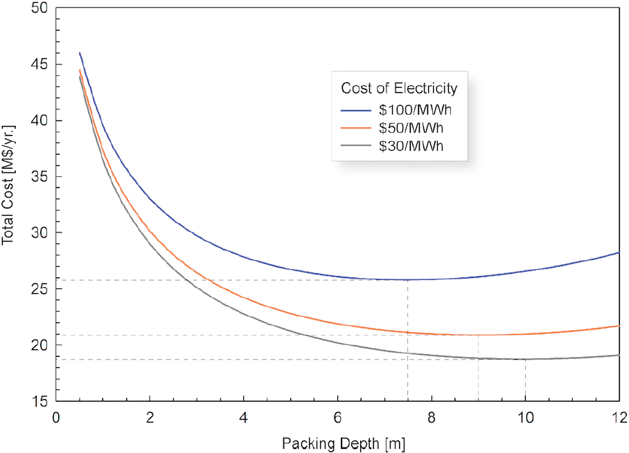
industrial systems (e.g., steel and cement making) that have large quantities of low-to high-quality waste heat available, fabrication of contactors with ultra-low capital materials (e.g., plastics), and system modeling to assess the viability of using direct air capture as a dedicated load option to solve congestion or curtailment issues in local or regional grids.
Demonstration
The most significant barrier to the assessment and deployment of direct air capture processes is the absence of process-scale operational data to perform accurate techno-economic analyses. Currently there is no incentive for privately funded demonstration projects to provide such data.
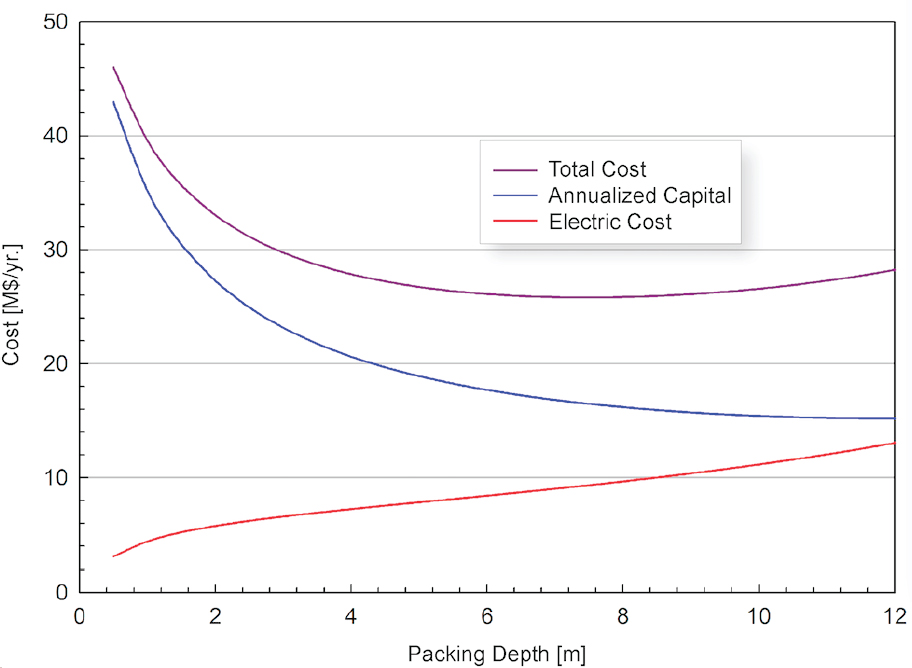
Today, essentially all process-scale operations have been conducted in private companies, which may not have an interest in disclosing operational data. Furthermore, in the absence of a globally accepted cost of carbon, there is little demand for processes designed for direct air capture and sequestration. To this end, the few commercial entities that exist are generally not practicing carbon removal because the CO2 obtained by direct air capture is sold for productive use, for example in greenhouses or the food and beverage industry. Although these opportunities are good for the budding array of commercial entities that are developing direct air capture technologies, they offer limited growth opportunities for the industry overall.
An array of publicly funded demonstration-scale studies of integrated direct air capture processes that can be operated for extended time periods is needed to generate data on process performance and reliability and to improve and refine process techno-economic models. The committee recommends a program that supports three
pilot-scale projects per at year at $20M each. Such projects should capture 1,000 t/y CO2 per project.
Such pilot-scale studies could assess the performance of solid sorbent–based processes, for example. As noted previously, the overall process cost is most sensitive to the capital cost of the solid sorbent, which is largely dictated by the price and operation lifetime of the sorbent. To date, most studies of sorbent stability have come from academia; essentially no data have released by commercial entities. Furthermore, most academic studies test under controlled, idealized laboratory conditions for limited time periods, and the results often cannot be easily extrapolated to larger scale operation. To this end, publicly funded pilot-scale studies that provide long-term data from field operations are needed to more accurately model sorbent durability and lifetime, which significantly affect the overall process cost of solid sorbent–based direct air capture processes.
Pilot-scale studies could also assess optimal site locations and plant configurations. Different direct air capture processes will likely be suited for specific deployment locales depending on the specific process characteristics involved (e.g., varied climates such as humid/arid, warm/cool). Furthermore, deployment location will impact operating and capital costs, which can be optimized based on the available energy resources locally. For example, if low-cost “stranded” carbon-free electricity (e.g., wind in Texas or Oklahoma) is available, then a plant could be designed with a deeper bed, which would enhance capture but increase electrical costs in the form of fan power to overcome the pressure drop. In these cases, the overall capital investment may be lower because the contactor surface area requirement may be smaller to capture the equivalent CO2.
Public funding for demonstration projects of direct air capture are also needed to accelerate movement along the operational learning curves for existing companies and to provide incentive for new companies to enter the field. Furthermore, public funding will ensure that operational data are available to the noncommercial research community to perform independent techno-economic analyses, to guide policymakers, and to make process innovations that will lead to improved direct air capture technologies.
The availability of data about process costs and energetics will lead to optimized designs that minimize these parameters, thereby leading to more rapid deployment of efficient processes. A single agency should be designated to set guidelines for data disclosure and sharing so that data are reported in a useful, uniform way, and are sufficient for accurate analysis of process costs and energetics.
Deployment
Direct air capture processes are expected to be initially deployed near locations where suitable geological sequestration is available, limiting or removing the need to develop long-distance CO2 pipeline networks. Broad deployment of carbon capture and sequestration from point sources will require creation of a more extensive CO2 pipeline network, which can be leveraged by direct air capture processes if appropriately sited. Other siting factors, such as (1) the potential for locally depleting the ambient CO2 concentration and thereby impacting agriculture or indigenous plant life, (2) proximity to appropriate sources of water when needed, and (3) proximity to renewable energy or thermal opportunities, should be considered to optimize the performance of the direct air capture plant and reduce impacts on the local communities.
Direct air capture processes may be scaled up (deployment of larger units) or scaled out (deployment of a large number of small units) to achieve necessary carbon removal targets, and it remains unclear whether one deployment mode is better than the other. Demonstration-scale plants of about 10,000 t/y CO2 would be of sufficient size to inform optimal siting for the various approaches.
Given the scale and financial commitment (~$100M per project) required for commercial-scale direct air capture systems, public investments should only be made after detailed engineering and economics analyses (stage-gate) have been performed and demonstrate a path to commercial viability. Public investments that subsidize initial nonreoccurring engineering costs for promising direct air capture technologies could be beneficial in accelerating direct air capture technology deployment.
Implementation of the Research Agenda
Institutions
The U.S. Department of Energy’s Office of Fossil Energy and National Energy Technology Laboratory (NETL) has the appropriate infrastructure to manage direct air capture research, development, and demonstration projects through a typical grant process that distributes funds to projects at universities, nonprofit research organizations, start-up companies, and large companies. Contractors that provide independent materials testing, component testing, techno-economic analysis, and professional engineering design can also be managed through the U.S. Department of Energy’s existing infrastructure. For development and demonstration testing of direct air capture components and systems, a centralized facility/national testbed akin to the NETL’s National Carbon Capture Center operated by the Southern Company (Figure 5.9) is recommended.
Funding
Scale of Funding
Over the past few decades, federal R&D funding as percentage of total funding has consistently shifted from demonstration and development to basic and applied research and away from industry to industry and national laboratories. To develop commercially viable direct air capture systems, funding levels will need to shift toward development and demonstration. The justification for this is as follows: It is generally accepted that the cost of scaling up a process follows the “2/3 law,” where the capital cost of plant kn at unit capacity cn, the cost of scaling is kn = k0(cn/c0)2/3, and k0 and c0 are the unit cost and capacity, respectively, of the reference plant. Assuming that a bench-scale process is 0.1 percent the capacity of a full-scale plant, pilot-scale is 1 percent of full-scale, and demonstration-scale is 10 percent of full-scale; then for every $1 spent on bench-scale development, roughly $5 should be spent on pilot-scale, and $20 on demonstration-scale.
Timing of Funding
Today, the maturity of direct air capture technologies spans the spectrum from basic materials research to pre-commercial system development and demonstration. To build a pipeline of technology from basic and applied research through deployment of systems, the committee recommends staggered funding, with an early focus on R&D that transitions to demonstration and deployment projects over a period of 15 years, as depicted in Figure 5.10. Each phase of funding should have stage-gates with technical and economics metrics. Notably, before funds are committed for demonstration-scale projects, detailed third-party engineering and economic assessments must demonstrate the potential for achieving CO2 removal at a cost of < $300/t.
Data Management
Data collection, organization, and public release is a critical component of a modern direct air capture research agenda. A central repository should be established to house the materials data as well as the results of engineering analyses and testing of direct air capture. In addition, standard engineering assessment methodologies should be developed, analogous to Matuszewski, 2014.
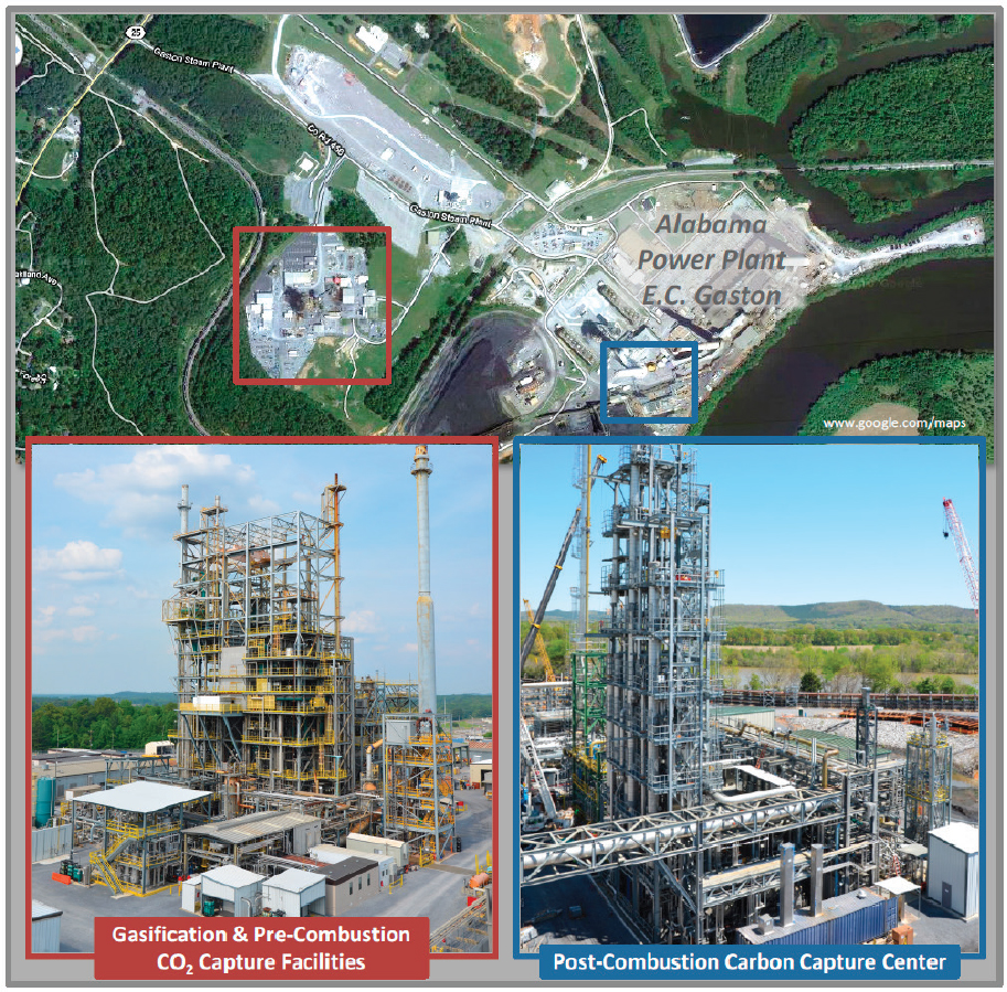
NOTES: Funded by the Office of Fossil Energy, U.S. Department of Energy, and operated by the Southern Company Services. Award No: DE-NT0000749, period: Oct 2008–Sep 2014, funding: $251M, federal: $200M; and Award No: DE-FE0022596, period: Jun 2014-May 2019, funding: $187M, federal: $37M.
SOURCE: NCCC, 2017.