


Below is the uncorrected machine-read text of this chapter, intended to provide our own search engines and external engines with highly rich, chapter-representative searchable text of each book. Because it is UNCORRECTED material, please consider the following text as a useful but insufficient proxy for the authoritative book pages.
22 Discussion of Proposed LRFD Bridge Design Pier Protection Guidelines Appendix A: Proposed LRFD Bridge Design Pier Protec- tion Specifications provides preliminary proposed guidelines for bridge pier protection for consideration in a future edi- tion of the AASHTO LRFD Bridge Design Specifications. The text has been based on the eighth edition of the AASHTO LRFD Bridge Design Specifications [AASHTO 2017], where strikeouts indicate proposed deletions from the eighth edi- tion text, and underlines indicate proposed additions based on the results of this research. Article 3.6.5 in the eighth edi- tion is identical to the language in the sixth edition. This sec- tion presents the development and illustrates the application of the guidelines for risk-based assessment of bridge pier protection shown in Appendix A. The bridge pier protection guidelines for the AASHTO LRFD Bridge Design Specifica- tions are presented here, and the passenger-vehicle occupant protection guidelines for the RDG are presented in the next chapter. Examples and validation with RSAPv3 are provided in a later chapter. Article 3.6.5 of the AASHTO LRFD Bridge Design Specifi- cations provides two design choices to the user: 1. Provide for structural resistance to heavy-vehicle impacts, or 2. Shield the pier system with a barrier. Providing structural resistance to heavy-vehicle impacts is discussed in Section 3.2, and shielding the pier system with a barrier for pier protection is discussed in Section 3.3. 3.1 Defining Bridge Collapse Before exploring the two design choices offered by the AASHTO LRFD Bridge Design Specifications, a definition of âbridge collapseâ must be established. As a point of comparison, Article 3.14 in the eighth edition dealing with vessel collisions does not define exactly what is meant by a âbridge collapse,â but it is noteworthy that the first sentence of Section 3.14.5 refers to âbridge component collapse.â This suggests that fail- ure of a pier component constitutes failure of the bridge itself regardless of whether the superstructure collapses. In essence, Article 3.14 ignores any potential redundancy in the pier sys- tem or any possible continuity of the superstructure over the piers being considered. Similarly, Article 3.6.5 of the eighth edition of the AASHTO LRFD Bridge Design Specifications dealing with impacts from vehicles takes essentially the same approach as Article 3.14 for vessels, meaning that the failure of any of the major bridge components constitutes failure or potential collapse of the entire bridge. From this point of view, failure of any of the major components will take the bridge out of service until the component is repaired. For example, if a column in a redundant multicolumn bridge-pier system is struck such that it completely fails, the bridge superstructure will not collapse because the pier system is redundant, but the bridge probably will be taken out of service while the pier column is repaired. This repair will likely take months to accomplish even if undertaken on an emergency basis, with the commen- surate repair, delay, and rerouting costs. On the other hand, using the same example, if the bridge superstructure itself collapses, the time and cost of repair, delay, and rerouting will be much higher since replacing the bridge is an even more costly and time-consuming activity. The potential for loss of life in the former is obviously smaller. There is no expectation that the structure will experience that type of load and expe- rience no damage. The approaches used in both Articles 3.6.5 and 3.14 in the eighth edition are, therefore, quite conserva- tive since failure of any component is equal to failure of the whole bridge under this definition. This definition is consid- ered to be too conservative at least for use in highway bridges exposed to vehicle traffic. It is preferable to take advantage of any redundancy of the pier system or continuity over the pier of the superstructure C H A P T E R 3
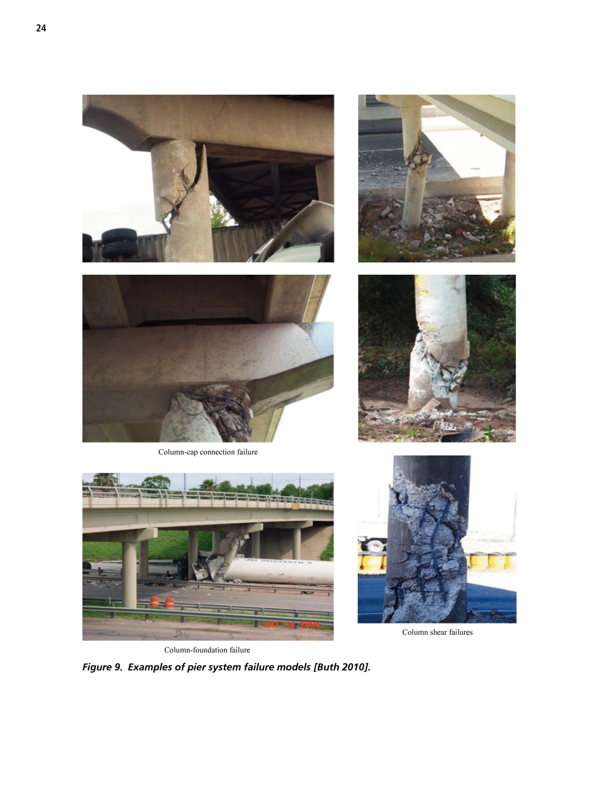
23 rather than ignore both. In this research, failure is defined as the inability of the superstructure to support its design dead load and permanent-lane live load. In other words, complete failure or collapse of a pier component is allowable as long as either the pier system is redundant, assuming the loss of that component, or the superstructure is continuous over the pier under consideration such that the loss of the pier component will not prevent the bridge superstructure from supporting its design dead load and permanent-lane live load. In essence, complete failure and loss of a pier component like a column is allowable as long as the superstructure does not collapse. Given this definition, bridge collapse will be highly unlikely to occur if: ⢠The critical pier components can be shown by calculation to have sufficient lateral impact resistance to the expected impact loads, ⢠The pier system can be shown by calculation to be redun- dant given the loss of a pier component, or ⢠The bridge superstructure can be shown by calculation to be continuous over the pier system such that the super- structure will not collapse. These three conditions will be discussed in the following sections. Each of these conditions requires the user to dem- onstrate by calculation that the criterion is satisfied. If any one of these conditions is true, the bridge pier system does not need to be protected by shielding barriers because it will be able to support its design dead load and permanent-lane live load. 3.1.1 Lateral Resistance to Impact In assessing the nominal resistance to lateral impact loads on bridge pier components, it is important to recognize that there are several possible failure modes. While a shear failure of a pier column is certainly one important mode, a column may also fail in flexure, the connection between the column and pier cap may fail, or the connection between the column and foun- dation may fail. In determining the lateral resistance to impact loading, the engineer must consider all possible failure modes and choose the model with the smallest lateral resistance as the controlling design element. Some of these failure modes are illustrated in Figure 9 using the cases collected by Buth et al. [Buth 2010]. The general LRFD design philosophy proceeds by assess- ing the nominal resistance or strength of each structural com- ponent and connection and is expressed by the following equation [AASHTO 2012]: âη γ ⤠ÏQ Ri i i i n where hi = load modification factor, γi = load factor, Qi = force effect, Ïi = resistance factor, and Rn = nominal resistance. This basic equation is used to evaluate each member and connection in a structure. The nominal resistance (Rn) is the calculated shear, moment, or axial strength of the member based on typical calculations or analysis. The resistance factor (Ïi) is used to account for variability in materials and work- manship that may reduce the nominal calculated resistance. On the left side of the equation, the applied loads are repre- sented by the force effect (Qi), which may be modified for uncertainty in the estimation of loads using the load factor (γi) and factors relating to ductility, redundancy, and opera- tional classification (hi). The load modification factor, load factor, and resistance factors are all intended to be statistical variables that account for the statistical variation of materials, loads, workmanship, and in-service use. Loads are characterized in the AASHTO LRFD Bridge Design Specifications in a variety of limit states. A heavy-vehicle impact is classified by the AASHTO LRFD Bridge Design Speci- fications as a Type II Extreme Event and is addressed in Arti- cles 1.3.2.5 and 3.4.1 [AASHTO 2012]. Table 3.4.1-1 of the AASHTO LRFD Bridge Design Specifications defines the over- load factor for Extreme Event II vehicle collision forces (CT) to be 1.0 (i.e., γ = 1.0). These events are rare and seldom expe- rienced in combination with other extreme events, so a value of unity is recommended. Load modification factors are characterized in the AASHTO LRFD Bridge Design Specifications in Article 1.3.2.5 and are classified by redundancy, ductility, and operational impor- tance [AASHTO 2012]. For the extreme event limit state, the load modification factors for ductility, redundancy, and operational importance are also all set to 1.00 in recognition that such events are rare. Section 5 (reinforced concrete) does not specify resistance factors to be used for extreme events, although Article 6.5.5 (steel construction) states that a value of 1.0 should be used. The seismic design section dealing with inelastic hinging forces on single columns and piers (AASHTO 2012, Arti- cle 3.10.9.4.3b) specifies that a resistance factor of 1.3 be used for reinforced concrete columns and 1.25 be used for struc- tural steel columns. Generally, resistance factors are taken to be less than 1.00, but in this case (i.e., inelastic hinges), the nominal calculated resistance is a service load value, so these values greater than 1.00 account for the additional strength of the members in the inelastic range that represents reserve capacity that can be counted on in an extreme event. The
24 Column-cap connection failure Column-foundation failure Column shear failures Figure 9. Examples of pier system failure models [Buth 2010].
25 simple-hinge method described in Appendix E: Nominal Resistance to Lateral Impact Loads on Pier Columns is an inelastic analysis method, so using a value of 1.00 or slightly greater would be appropriate and consistent with the seismic provisions if that method were used to calculate the pier col- umn hinge capacity. Given this general background, the basic LRFD design equa- tion can be rewritten explicitly for piers subjected to Extreme Event II lateral vehicle collision forces as: η η η γ ⤠ÏCT CT CPC CPCQ RD R I where hD = 1.00 = ductility load modification factor for Extreme Event II vehicle collision forces (AASHTO 2012, Article 1.3.3); hR = 1.00 = redundancy load modification factor for Extreme Event II vehicle collision forces (AASHTO 2012, Article 1.3.4); hI = 1.00 = operational importance load modification factor for Extreme Event II vehicle collision forces (AASHTO 2012, Article 1.3.5); γCT = 1.00 = overload factor for vehicle collision forces (AASHTO 2012, Table 3.4.1-1); QCT = expected lateral heavy-vehicle collision force on the critical pier component; ÏCPC = 1.30 = resistance factor for inelastic hinge forces in reinforced concrete columns and piers (AASHTO 2012, Article 3.10.9.4.3b), 1.25 = resistance factor for inelastic hinge forces in structural steel columns and piers (AASHTO 2012, Article 3.10.9.4.3b), 1.00 = resistance factor for inelastic hinge forces in reinforced concrete columns if the simple- hinge method in Appendix E is used to find RCPC; and RCPC = nominal lateral load resistance of the critical pier component. Generally speaking, the gravity loads in a pier system are supported either by columns or walls. Columns may be circu- lar or rectangular and may either have a bent or cap spanning several columns or directly supporting a girder. Columns as small as 18 in. have been observed. Walls may span the entire width of the overpassing bridge, or they may be the base of a hammerhead-type cap. In either case, walls are much longer than they are wide. Typical thicknesses are around 4 ft, and lengths are generally 15 ft or more. For example, a 15.5-ft-long by 5-ft-deep hammerhead pier has a nominal shear capacity based on just the concrete shear strength of over 900 kipsâ well above the current impact design load of 600 kips [FHWA 2014a]. 3.1.1.1 Pier Walls Article 5.8.3.3 of the eighth edition of the LRFD Bridge Design Specifications provides the procedure for calculating the nominal shear strength of compression members. For a wall-type structure with no prestressing, Article 5.8.3.3 assumes that the concrete alone is sufficient for developing adequate shear strength. For walls, the following equation generally controls: = β â²0.0316 0.72V f L Wc c P P where Vc = the shear strength of concrete in ksi, β = 2, LP = length of the pier wall in ft, and WP = thickness of the pier wall in ft. Assuming a minimum wall thickness of 48 in., concrete strength of 4 ksi, and β of 2, and recognizing that there are two shear planes in a vehicle impact, the minimum length of a wall that will generate 600 kips of capacity using just the concrete can be found as: = β â²0.0316 0.72V f L Wc c P P 600 2 0.0316 2 4 0.72 48 68 in. 5.7 ftL bP v( ) ( ) ( )= â = = Generalizing, this results in 600/(2 ⢠0.0316 ⢠2 ⢠2 ⢠0.72) = 3,296 = LP WP Figure 10 shows the relationship between the pier wall thickness and length needed for a shear capacity of 600 kips based only on the contribution of the concrete. Points that plot above and to the right of the line can be considered pier walls with more than 600 kips of available shear capacity, whereas points that plot below and to the left of the line should be considered columns. A typical two-lane bridge would be on the order of 30 ft wide, so if a pier wall the entire width of the structure were used, Figure 10 suggests that a wall at least 1 ft thick would be sufficient. Figure 10 illustrates that pier walls will seldom be at risk in heavy-vehicle collisions. Figure 11 shows the possible impact orientations for pier walls. The wall may be struck end-on, in which case the full shear capacity of the massive wall will resist the vehicle. This impact orientation would not be particularly vulnerable to failure if the dimensions of the wall plot above and to the right of the line in Figure 10. On the other hand, the wall may also be struck in the middle and may be susceptible to the vehicle punching through it even though the component of the force perpendicular to the wall would be considerably less than in the end-on case. Even this scenario, however, seems unlikely to experience failure since from rigid concrete
26 barrier design experience it is known that a 10-in. thick TL-5 vertical concrete wall properly reinforced and with proper foundation will contain and redirect an 80,000-lb tractor- trailer truck [AASHTO 1994a]. Anecdotally, it is perhaps sig- nificant that none of the bridge pier collisions investigated by Buth involved bridge piers that were in a wall configuration. Pier walls will generally not be at high risk of failure when struck even by large trucks [Buth 2010]. 3.1.1.2 Pier Columns Bridge piers composed of columns either directly support- ing girders or supporting a pier cap appear to be the most common type of pier in the National Highway System. Such columns may have cross-sections that are circular, square, or rectangular. The typical bridge pier system in the National Highway System in Ohio, for example, consists of three 36-in.-diameter cap-and-column piers [ODOT 2007]. Gen- erally, the column is about 15 ft tall as measured from the top of the footing or ground line to the bottom of the pier cap. Typical longitudinal reinforcement is proportioned as 1% of the gross area of the column, and typical shear reinforcement uses #4 spiral bars with a 4.5-in. pitch and 30-in. outside diameter (i.e., 3 in. of cover). Like many states, ODOTâs exist- ing bridge piers largely date from the Interstate construction era of the 1960s and 1970s. Bridge piers from this era tend to be dominated by this type of cap-and-column design. Minnesota DOT has similar design guidelines [MNDOT 2016]. The minimum column diameter for a cap-and-column pier design is 28 in. For columns less than 42 in. in diameter, spiral reinforcement is required with a pitch of no less than 3 in. and at least #4 bars. For circular columns greater than 42 in. in diameter or all square and rectangular columns, ties no smaller than #3 can be used, with various sized ties specified based on the longitudinal steel selected for the gravity loads. TXDOT allows the use of circular columns as small as 18 in., and for all circular columns between 18 and 48 in., #3 spirals with a 6-in. pitch are specified [TXDOT 2013]. Wisconsin requires at least three columns in a cap-and-column pier, and the small- est allowable column size is 30 in. [WIDOT 2013a]. Columns use ties rather than spirals. Wisconsin treats the design of hammer head piers as a wall. Figure 12 illustrates the typical impact scenarios for piers with columns. Due to the symmetry of the columns, the Figure 10. Minimum wall thickness and length needed for at least 600 kips of shear capacity from only the concrete. Figure 11. Possible impact orientations for pier walls.
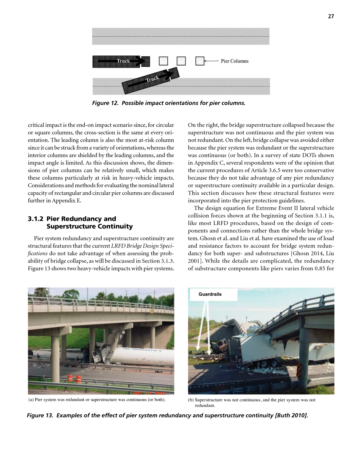
27 critical impact is the end-on impact scenario since, for circular or square columns, the cross-section is the same at every ori- entation. The leading column is also the most at-risk column since it can be struck from a variety of orientations, whereas the interior columns are shielded by the leading columns, and the impact angle is limited. As this discussion shows, the dimen- sions of pier columns can be relatively small, which makes these columns particularly at risk in heavy-vehicle impacts. Considerations and methods for evaluating the nominal lateral capacity of rectangular and circular pier columns are discussed further in Appendix E. 3.1.2 Pier Redundancy and Superstructure Continuity Pier system redundancy and superstructure continuity are structural features that the current LRFD Bridge Design Speci- fications do not take advantage of when assessing the prob- ability of bridge collapse, as will be discussed in Section 3.1.3. Figure 13 shows two heavy-vehicle impacts with pier systems. On the right, the bridge superstructure collapsed because the superstructure was not continuous and the pier system was not redundant. On the left, bridge collapse was avoided either because the pier system was redundant or the superstructure was continuous (or both). In a survey of state DOTs shown in Appendix C, several respondents were of the opinion that the current procedures of Article 3.6.5 were too conservative because they do not take advantage of any pier redundancy or superstructure continuity available in a particular design. This section discusses how these structural features were incorporated into the pier protection guidelines. The design equation for Extreme Event II lateral vehicle collision forces shown at the beginning of Section 3.1.1 is, like most LRFD procedures, based on the design of com- ponents and connections rather than the whole bridge sys- tem. Ghosn et al. and Liu et al. have examined the use of load and resistance factors to account for bridge system redun- dancy for both super- and substructures [Ghosn 2014, Liu 2001]. While the details are complicated, the redundancy of substructure components like piers varies from 0.85 for Figure 12. Possible impact orientations for pier columns. Guardrails (a) Pier system was redundant or superstructure was continuous (or both). (b) Superstructure was not continuous, and the pier system was not redundant. Figure 13. Examples of the effect of pier system redundancy and superstructure continuity [Buth 2010].
28 non redundant piers up to about 1.05 for redundant pier sys- tems [Ghosn 2014, Appendix A, Article 1.3.6.2]. In the con- text of piers, Ghosn et al. define redundancy as a pier system with two or more columns supporting the bent and detailing sufficient to allow plastic moment capacity of the columns to develop. Similarly, the system factors for the superstructure under vertical loads (i.e., traffic live loads and dead loads) are between 0.80 and 1.20, depending on the structural form of the cross-section [Ghosn 2014, Appendix A, Article 1.3.6.1]. The Ghosn recommendations have not, as yet, been incor- porated into the LRFD Bridge Design Specifications, but they do provide some insight into accounting for pier redundancy and superstructure continuity in the case of pier components subjected to vehicle impacts. The system factors as developed by Ghosn et al. are resis- tance factors that are used to reduce the nominal strength of the bridge component, in this case the critical pier compo- nent. A low value of the system factor would cause the engi- neer to increase (i.e., overdesign) the strength of the member to provide additional capacity to guard against system failure. The purpose of these guidelines, however, is somewhat dif- ferent in that the guidelines are meant to estimate the prob- ability of failure rather than provide a criterion for design. Table 5 and Table 6 show the types of structural character- istics that determine the redundancy of the pier system and continuity of the superstructure. An alternative, simpler approach for addressing redun- dancy is illustrated by the Minnesota DOT Bridge Office Sub structure Protection Policy from 2007 and their updated guidance in 2016 [MNDOT 2007b, MNDOT 2016]. The policy is categorized by a variety of design cases and preferred solu- tion strategies. Pier systems with two or fewer columns sup- porting a bent are categorized as nonredundant. When there are three or more columns in the pier system, the designer must âvalidate that the structure will not collapse by analyz- ing the structure considering removal of any single column. Consider all dead load with a 1.1 load factor. Use live load only on the permanent travel lanes, not the shoulders, with a 1.0 load factorâ [MNDOT 2007b]. The purpose of this load case is to provide sufficient time for any traffic on the bridge to clear after a bridge pier collision without the superstruc- ture collapsing. The same rationale can be used for evaluat- ing superstructure continuity. For the proposed guidelines, it is suggested that a pier system be considered redundant or a superstructure continuous if it is demonstrated by calcula- tion that the bridge can support all its dead load with a load factor of 1.1 and the design live load on the permanent lanes (i.e., not the shoulders) with a load factor or 1.0. This is the approach that was taken in developing the proposed LRFD Bridge Design Specifications guidelines shown in Appendix A. 3.1.3 Acceptance Criteria Now that a definition of bridge collapse has been chosen, the values for the acceptance criterion need to be established. The acceptance criterion is the maximum probability of bridge collapse that is acceptable to the owner agency. One aspect of Article 3.14 dealing with vessel collisions of interest here is the acceptance limit for the expected annual frequency of bridge component collapse. Article 3.14.5 dealing with vessel collisions states that: [F]or critical or essential bridges, the maximum annual fre- quency of collapse, AF, for the whole bridge, shall be taken as 0.0001. For typical bridges, the maximum frequency of collapse, AF, for the whole bridge, shall be taken as 0.001 [AASHTO 2012]. In essence, critical or essential bridges have an âimportance factorâ of 10 with respect to more typical bridges. The com- mentary for Section C3.6.5.1 dealing with vehicle collisions in the eighth edition of the LRFD Bridge Design Specifications uses this same acceptance criterion in stating: Design for collision force is not required if AFHBP is less than 0.0001 for critical or essential bridges or 0.001 for typical bridges [AASHTO 2017]. Nonredundant Pier Systems ÏPR = Value If any of the following are true, the pier system is not redundant: ⢠One column supports a bent. ⢠System failure is controlled by shear. ⢠Column connections with the bent or foundation have insufficient detailing to allow the full plastic moment capacity of the column to develop. 0.85 Redundant Pier Systems Value Columns If all of the following are true, the pier system is redundant: ⢠Two or more columns support the bent. ⢠There are integral connections between the superstructure and substructure. ⢠Detailing is sufficient to allow the full plastic moment capacity of the columns to develop. ÏPR = 0.95 1.00 1.05 3 2 4+ Table 5. System factors for pier redundancy (ePR) [adapted from Ghosn 2014].
29 Since the eighth edition of the LRFD Bridge Design Specifi- cations uses a value of 0.0001 for essential bridges and 0.001 for typical bridges in both the vessel collision provisions in Article 3.14 as well as the heavy-vehicle collisions in Arti- cle 3.6.5, there appears to be some history of using these values for the critical acceptance annual risk for bridge col- lapse. These values are retained in this research, although they can be modified by AASHTO should it want to make the acceptance criteria either more or less conservative. 3.2 Design Choice Is Structural Resistance 3.2.1 Practical Worst-Case Collision Force: QCT The objective of developing pier protection guidelines is to minimize the chance of bridge collapse due to heavy-vehicle collisions with pier components. The most vulnerable type of pier components are generally pier columns. It is necessary to estimate the probable range and distribution of extreme event impact forces in heavy-vehicle impacts with pier components. Appendix D: Lateral Impact Loads on Pier Columns provides a discussion of the finite element modeling of tractor-trailer truck impacts with bridge columns as well as a comparison to the tractor-trailer rigid-pole tests conducted by Buth et al. [Buth 2011]. The forceâtime history in Figure 14 shows the origin of the 600-kip design load used in the eighth edition of the LRFD Bridge Design Specifications. The engine impact with the rigid pole created a peak force of just over 600 kips. The particular magnitude of this peak force is dependent on the filter strategy used in analyzing the data; the 10-ms average first peak was over 900 kips, and the 25-ms average was just over 600 kips. Buth et al. chose the 25-ms average acceleration as being essentially equivalent to the quasi-static design load, and this was adopted in the eighth edition. The results of the analyses described in Appendix D and summarized in Figure 14 show that the peak impact force is not a function of the total mass and speed of the vehicle but, rather, the impact is actually a series of loosely coupled impact events. The first major event is the collision of the essentially rigid engine block with the pier, followed by the crushing of the tractor cabin and eventually the impact with the front of the trailer. While the trailer load could potentially subject the pier to a large loading if it were massive and rigid, the first practical worst-case impact force (QCT) was found to be directly related to the impact between the truck engine and the pier column. The engine is the first large essentially rigid mass that is encountered in a head-on impact, and it domi- nates the impact forceâtime history. In other words, the total kinetic energy of the vehicle is not predictive of the practical worst-case impact force (QCT). The structural design of bridges and bridge piers is accom- plished primarily in the force domain, whereas collisions occur in the energy and momentum domains. It is necessary, there- fore, to transform the dynamic impact forceâtime response into an equivalent quasi-static load that can be used as a design criterion. An approach to estimating the peak impact load was developed by assuming that the early phases of the impact can be represented by two square wave impulses: one caused by the frame and body structures between the column and the front of the engine, and the second caused by the engineâcolumn impact. The following simple equation provided good and slightly conservative predictions of the finite element analy- sis (FEA) impact force at impact velocities between 35 and 50 mph. i i i i i i32.2 1000 32.2 1000 CT 1Q W V T W V T d V e e f e =     + +            ÏSU SC = Value Superstructure Cross-Section Type 0.80-0.96 Continuous steel I-girder with non-compact negative bending sections [see Ghosn 2014, Appendix A, Table 1.3.6.1-1]. 0.80-1.20 All other simple span and continuous I-girder bridges [see Ghosn 2014, Appendix A, Table 1.3.6.1-1]. 0.83-0.97 Simple span box-girder bridges ⤠⤠24 ft wide [see Ghosn 2014, Appendix A, Table 1.3.6.1-2]. 0.80-1.20 Simple span box-girder bridges >24 ft wide [see Ghosn 2014, Appendix A, Table 1.3.6.1-2]. 0.80-1.20 Continuous box-girder bridges 24 ft wide [see Ghosn 2014, Appendix A, Table 1.3.6.1-2]. 0.80-1.20 Continuous steel box-girders w/non-compact negative bending sections [see Ghosn 2014, Appendix A, Table 1.3.6.1-2]. 0.80-1.20 Continuous box-girder bridges with compact negative bending sections [see Ghosn 2014, Appendix A, Table 1.3.6.1-2]. 0.80 Single-cell box-girder bridge [see Ghosn 2014, Appendix A, Table 1.3.6.1-3]. 1.00 Multicell box-girder bridge [see Ghosn 2014, Appendix A, Table 1.3.6.1-3]. Table 6. System factors for superstructure continuity (eSU SC) [adapted from Ghosn 2014].
30 where We = effective weight of engine (lb), Wf = effective weight of structure in front of the engine (lb), Te = period of the engine pulse (s), d1 = distance from front bumper to front of engine (ft), V = impact velocity (ft/s), and QCT = practical worst-case impact force (kips). All of the variables in this equation for QCT are normal ran- dom variables. Typical values based on the dimensions and masses of commonly used crash-test vehicles are shown to the right of the equationâs where list. The impact velocity in particular is expected to have an important effect on the dis- tribution of impact forces. To determine the cumulative distribution of impact forces that are likely given that a heavy-vehicle impact occurs with a pier system component, this equation was used in a Monte Carlo simulation to generate data for a cumulative distribu- tion. In a Monte Carlo simulation, a random number is gen- erated and used to choose a particular value for each random variable according to the known statistical parameters of that distribution; for a normal distribution, the mean and the Tractor Trailer Single-Unit Truck 4,500 1,965 3,000 1,310 0.0241 0.0241 1.146 2.210 standard deviation are sufficient. Monte Carlo simulations using 25,000 cases per category were performed for speeds of between 35 and 75 mph in 5 mph increments for each of the four functional classes to be used in the guidelines (i.e., rural Interstate, rural collector, urban Interstate, and urban collec- tor). The cumulative distributions created using these Monte Carlo simulations are shown in Figure 15 through Figure 18, which plot the nominal lateral resistance (RCPC) on the x-axis and the probability of the impact force (QCT) exceeding the nominal lateral resistance (RCPC) on the y-axis. For example, the probability of exceeding a nominal lateral resistance (RCPC) of 600-kip on a 55-mph rural Interstate is shown by Figure 15 to be 0.50, whereas the probability of exceeding a nominal lateral resistance (RCPC) of 600-kip on a 45-mph urban col- lector is 0.0140, as shown in Figure 18. Figure 15 through Figure 18 show several interesting features. First, as expected, for a nominal lateral resistance (RCPC), the probability of exceeding that force increases as the posted speed limit (PSL) increases. Second, all four fig- ures have a unique âSâ shape where the smaller nominal lateral resistances (RCPC) are primarily associated with the lighter single-unit trucks, and the higher nominal lateral resistances (RCPC) are associated with heavier tractor-trailer trucks. The nature of the âSâ is controlled by the proportion of each type of truck on each functional class of roadway. Figure 14. Forceâtime history for Test 429730-2 and finite element analysis (FEA) results indicating key impact events.
31 Figure 15. Cumulative distribution of expected impact force â rural Interstates/primaries.
32 28 Figure 16. Cumulative distribution of expected impact force â rural collectors.
33 Figure 17. Cumulative distribution of expected impact force â urban Interstates/primaries.
34 32 Figure 18. Cumulative distribution of expected impact force â urban collectors.
35 These figures indicate that large impact forces are primarily associated with tractor trailers, as expected. This is also con- firmed by Table 3 and Table 4, where all but two of the 24 real- world crashes found in the literature involved tractor trailers. Of the two nonâtractor-trailer trucks, one was an intercity bus that did not cause the pier column to fail, and the other was a single-unit truck that caused the column to fail but did not cause the bridge to collapse. There were 16 cases where a truck caused the pier column to fail, and all but one was a tractor- trailer truck. Table 3 also lends support to the idea that the total weight of the truck is not determinative of pier column failure. While some cases did involve very heavy vehicles haul- ing heavy, rigid loads, at least one (e.g., Buth #19 [Buth 2010]) was an unloaded tractor-trailer that was still able to cause a pier column to fail. Figure 15 through Figure 18 are shown in guideline form in Table 7. The user enters the table for the appropriate func- tional classification of the roadway of interest with nominal lateral load capacity of the column (RCPC) and reads over to the column corresponding to the PSL of interest. The value tabulated is the probability that the impact force (QCT) will exceed the nominal lateral load capacity of the column (RCPC). In Table 7, the probability of exceeding the nominal lat- eral resistance increases in each row as the PSL increases, as expected. Similarly, the probability of exceeding the nominal lateral resistance decreases in each column as the nominal lat- eral resistance increases, which is also as expected. If the prob- ability of exceeding a nominal lateral resistance of 600 kips on a 65-mph roadway is examined in Table 7, the highest prob- ability of exceed the lateral resistance is 0.76 (rounded) on a rural primary route. Rural primary roadways have the high- est percentage of tractor trailers of the four functional class categories, and the long-distance movement of goods is one of the primary functions of rural primary routes. The prob- ability of exceeding 600 kips on a 65-mph rural collector is much less (i.e., 0.32 rounded) because there are fewer tractor- trailer trucks, and the weight distribution on those roads is not as heavy. Similarly, a pier located on a 65-mph urban primary highway would have a probability of 0.65 (rounded) of exceeding 600 kips, a little lower than the rural primary roads because the percentage of trucks is somewhat lower. Like the rural collectors, a bridge pier on a 65-mph urban collector would have a probability of exceeding 600 kips of only 0.22 (rounded) because the heavy-vehicle mix is domi- nated by smaller, lighter, single-unit trucks. In other words, the data summarized in Figure 15 through Figure 18 and Table 7 make intuitive sense. The most at-risk piers are those on high-speed rural Interstates, whereas those on low-speed urban collectors are at relatively low risk, all other character- istics being equal. 3.2.2 Design Load Appendix D describes scaled model impact tests, finite element impact analyses of the representative pier column designs, a full-scale tractor-trailer truck crash test, and finite element analyses of 80,000-lb tractor-trail truck impacts with the representative pier designs. The research team suggests that the current LRFD Bridge Design Specifications recom- mendation of a 600-kip lateral load capacity be retained. This value was based on the peak 25-ms impact force observed in a full-scale 50-mph head-on crash test of an 80,000-lb tractor- trailer truck and a rigid column. The analyses described in Appendix D showed that circular columns 30 in. in diameter and smaller are likely to fail in an impact with an 80,000-lb tractor-trailer truck striking the column head-on at 50 mph. Such columns generally have a simple-hinge lateral impact load capacity of under 600 kips, so they are at high risk of catastrophic failure in the field. The 600-kip design load, however, should not be limited to the shear capacity of the column. The limiting loading may arise from any of the following: ⢠Shear strength of the column, ⢠Flexural strength of the column, ⢠Connection strength between the column and pier cap or bent, or ⢠Connection strength between the column base and foundation. In accessing the nominal lateral capacity, the user should determine which of these components is the limiting loading on the pier component. 3.2.3 Point of Load Application The eighth edition of the LRFD Bridge Design Specifications recommends that the 600-kip impact load be applied to the column 5 ft above the grade [AASHTO 2017], but the FEA described in Appendix D shows clearly that the peak load is associated with the impact of the engine of the tractor, which is located much lower, typically at the bumper level of 2 ft. The impact load should be applied at a distance between 2 and 5 ft, whichever results in the worst-case loading. The guidelines user should check not only the impact load capac- ity at the level of impact but also the resulting moments at the pier cap and foundation to ensure that the connections have sufficient strength to resist the impact. For example, 2 ft might be used when assessing the columnâcap connection because this would maximize the moment on the connection, whereas 5 ft might be appropriate for assessing the columnâ foundation connection.
36 RCPC â¤45 50 55 60 65 70 75 â¤45 50 55 60 65 70 â¥75 100 0.9999 1.0000 1.0000 1.0000 1.0000 1.0000 1.0000 1.0000 1.0000 1.0000 1.0000 1.0000 1.0000 1.0000 150 0.9939 0.9989 0.9999 1.0000 1.0000 1.0000 1.0000 0.9817 0.9969 0.9993 1.0000 1.0000 1.0000 1.0000 200 0.9063 0.9629 0.9890 0.9966 0.9992 0.9996 0.9999 0.6980 0.8826 0.9609 0.9892 0.9960 0.9994 0.9998 250 0.8058 0.8422 0.9049 0.9565 0.9824 0.9935 0.9974 0.3710 0.5055 0.7018 0.8602 0.9431 0.9792 0.9930 300 0.7931 0.7928 0.8125 0.8566 0.9116 0.9533 0.9771 0.3322 0.3429 0.4023 0.5462 0.7134 0.8523 0.9283 350 0.7892 0.7884 0.7907 0.7996 0.8279 0.8684 0.9142 0.3302 0.3315 0.3350 0.3657 0.4455 0.5800 0.7291 400 0.7584 0.7832 0.7886 0.7902 0.7978 0.8079 0.8370 0.3179 0.3294 0.3300 0.3374 0.3464 0.3897 0.4873 450 0.6440 0.7550 0.7820 0.7887 0.7931 0.7914 0.7990 0.2720 0.3177 0.3280 0.3358 0.3327 0.3357 0.3622 500 0.4232 0.6620 0.7552 0.7817 0.7912 0.7894 0.7901 0.1797 0.2770 0.3163 0.3328 0.3313 0.3296 0.3360 550 0.1964 0.4754 0.6731 0.7570 0.7843 0.7879 0.7888 0.0817 0.1993 0.2837 0.3213 0.3290 0.3285 0.3323 600 0.0597 0.2628 0.5216 0.6903 0.7602 0.7810 0.7870 0.0254 0.1086 0.2163 0.2895 0.3183 0.3261 0.3313 650 0.0125 0.1054 0.3292 0.5582 0.6999 0.7584 0.7790 0.0056 0.0432 0.1397 0.2356 0.2942 0.3174 0.3287 700 0.0016 0.0312 0.1614 0.3816 0.5883 0.7076 0.7586 0.0008 0.0130 0.0657 0.1645 0.2463 0.2956 0.3193 750 0.0002 0.0067 0.0584 0.2132 0.4338 0.6144 0.7095 0.0000 0.0028 0.0253 0.0916 0.1833 0.2550 0.2998 800 0.0000 0.0008 0.0177 0.0958 0.2706 0.4781 0.6263 0.0000 0.0005 0.0070 0.0429 0.1129 0.1975 0.2666 850 0.0000 0.0001 0.0048 0.0361 0.1390 0.3246 0.5072 0.0000 0.0001 0.0016 0.0158 0.0610 0.1343 0.2167 900 0.0000 0.0000 0.0007 0.0098 0.0594 0.1934 0.3692 0.0000 0.0000 0.0003 0.0048 0.0269 0.0796 0.1571 950 0.0000 0.0000 0.0001 0.0024 0.0224 0.0988 0.2362 0.0000 0.0000 0.0001 0.0012 0.0107 0.0400 0.0998 1,000 0.0000 0.0000 0.0000 0.0006 0.0065 0.0431 0.1363 0.0000 0.0000 0.0001 0.0002 0.0033 0.0165 0.0559 1,050 0.0000 0.0000 0.0000 0.0000 0.0018 0.0155 0.0670 0.0000 0.0000 0.0000 0.0000 0.0010 0.0063 0.0260 1,100 0.0000 0.0000 0.0000 0.0000 0.0006 0.0054 0.0285 0.0000 0.0000 0.0000 0.0000 0.0002 0.0018 0.0117 1,150 0.0000 0.0000 0.0000 0.0000 0.0001 0.0015 0.0102 0.0000 0.0000 0.0000 0.0000 0.0000 0.0005 0.0042 1,200 0.0000 0.0000 0.0000 0.0000 0.0000 0.0001 0.0034 0.0000 0.0000 0.0000 0.0000 0.0000 0.0002 0.0014 1,250 0.0000 0.0000 0.0000 0.0000 0.0000 0.0000 0.0011 0.0000 0.0000 0.0000 0.0000 0.0000 0.0001 0.0004 1,300 0.0000 0.0000 0.0000 0.0000 0.0000 0.0000 0.0002 0.0000 0.0000 0.0000 0.0000 0.0000 0.0000 0.0001 Rural CollectorsRural Interstates and Primaries Posted Speed Limit (mi/hr)Posted Speed Limit (mi/hr) ⥠RCPC â¤45 50 55 60 65 70 75 â¤45 50 55 60 65 70 â¥75 100 1.0000 1.0000 1.0000 1.0000 1.0000 1.0000 1.0000 1.0000 1.0000 1.0000 1.0000 1.0000 1.0000 1.0000 150 0.9924 0.9986 0.9996 0.9999 1.0000 1.0000 1.0000 0.9798 0.9961 0.9996 0.9997 0.9999 1.0000 1.0000 200 0.8599 0.9419 0.9813 0.9947 0.9987 0.9995 0.9998 0.6462 0.8638 0.9551 0.9870 0.9969 0.9990 0.9996 250 0.7093 0.7597 0.8573 0.9322 0.9743 0.9903 0.9966 0.2676 0.4239 0.6550 0.8368 0.9350 0.9763 0.9908 300 0.6915 0.6837 0.7196 0.7815 0.8663 0.9264 0.9673 0.2228 0.2396 0.3082 0.4745 0.6701 0.8248 0.9155 350 0.6876 0.6769 0.6858 0.6962 0.7394 0.7954 0.8723 0.2211 0.2260 0.2274 0.2599 0.3610 0.5123 0.6816 400 0.6622 0.6728 0.6832 0.6832 0.6890 0.7054 0.7587 0.2129 0.2245 0.2228 0.2237 0.2410 0.2901 0.3987 450 0.5611 0.6504 0.6791 0.6816 0.6826 0.6795 0.6997 0.1798 0.2166 0.2210 0.2216 0.2258 0.2295 0.2579 500 0.3724 0.5678 0.6562 0.6764 0.6812 0.6764 0.6869 0.1187 0.1887 0.2139 0.2199 0.2248 0.2223 0.2245 550 0.1718 0.4055 0.5845 0.6542 0.6758 0.6751 0.6850 0.0552 0.1377 0.1914 0.2128 0.2227 0.2211 0.2208 600 0.0513 0.2231 0.4522 0.5932 0.6544 0.6681 0.6833 0.0161 0.0742 0.1486 0.1932 0.2151 0.2191 0.2200 650 0.0110 0.0886 0.2836 0.4795 0.6024 0.6485 0.6775 0.0029 0.0284 0.0937 0.1574 0.1975 0.2134 0.2180 700 0.0010 0.0252 0.1410 0.3302 0.5068 0.6042 0.6589 0.0003 0.0079 0.0461 0.1071 0.1666 0.1998 0.2118 750 0.0002 0.0051 0.0529 0.1847 0.3724 0.5194 0.6170 0.0000 0.0019 0.0172 0.0592 0.1246 0.1741 0.1992 800 0.0000 0.0005 0.0155 0.0851 0.2344 0.4050 0.5437 0.0000 0.0003 0.0054 0.0266 0.0758 0.1356 0.1761 850 0.0000 0.0001 0.0038 0.0315 0.1200 0.2770 0.4387 0.0000 0.0000 0.0012 0.0100 0.0417 0.0924 0.1435 900 0.0000 0.0000 0.0008 0.0092 0.0529 0.1636 0.3200 0.0000 0.0000 0.0003 0.0026 0.0182 0.0554 0.1055 950 0.0000 0.0000 0.0001 0.0022 0.0184 0.0836 0.2076 0.0000 0.0000 0.0000 0.0005 0.0067 0.0279 0.0698 1,000 0.0000 0.0000 0.0000 0.0003 0.0055 0.0356 0.1186 0.0000 0.0000 0.0000 0.0001 0.0018 0.0116 0.0411 1,050 0.0000 0.0000 0.0000 0.0000 0.0016 0.0138 0.0584 0.0000 0.0000 0.0000 0.0000 0.0006 0.0041 0.0210 1,100 0.0000 0.0000 0.0000 0.0000 0.0004 0.0042 0.0252 0.0000 0.0000 0.0000 0.0000 0.0001 0.0015 0.0088 1,150 0.0000 0.0000 0.0000 0.0000 0.0000 0.0010 0.0104 0.0000 0.0000 0.0000 0.0000 0.0000 0.0004 0.0038 1,200 0.0000 0.0000 0.0000 0.0000 0.0000 0.0001 0.0031 0.0000 0.0000 0.0000 0.0000 0.0000 0.0002 0.0013 1,250 0.0000 0.0000 0.0000 0.0000 0.0000 0.0000 0.0008 0.0000 0.0000 0.0000 0.0000 0.0000 0.0000 0.0004 1,300 0.0000 0.0000 0.0000 0.0000 0.0000 0.0000 0.0002 0.0000 0.0000 0.0000 0.0000 0.0000 0.0000 0.0001 Urban CollectorsUrban Interstates and Primaries Posted Speed Limit (mi/hr) Posted Speed Limit (mi/hr) ⥠Table 7. Probability of impact force (QCT) exceeding critical pier component nominal lateral resistance (RCPC).
37 3.3 Design Choice Is Shielding with a Barrier If the design choice is to shield the bridge pier system, the bridge engineer should evaluate whether a shielding barrier is necessary given the traffic, site, and structural characteristics of the pier system. The procedure suggested for evaluating bridge piers for protection is outlined in Table 8 and involves finding the following four values: HVEi = The expected annual number of heavy- vehicle encroachments in direction i is found using Table 13 using the highway type, traffic volume, and percentage of trucks. Ni = The site-specific adjustment factor is found using Table 15 and the character- istics of the study site. P(C|HVEi) = The probability of a crash given a heavy- vehicle encroachment in direction i is found by using Table 19 using the pier component offset and size in each direc- tion i. P(QCT>RCPC|C) = The probability of the worst-case col- lision force (QCT) exceeding the critical pier component capacity (RCPC) from Table 7. The product of these four values is the estimated annual frequency of bridge collapse for the unshielded pier. If this value is less than 0.0001 for a critical bridge or 0.0010 for a typical bridge, the pier system need not be shielded for pier protection. If this value is greater than or equal to 0.0001 for a critical bridge or 0.0010 for a typical bridge, the pier system should be shielded with a rigid concrete MASH TL-5 barrier that is at least 42 in. tall. The research to determine these four values and apply them to assessing the need for pier protec- tion is presented in the following sections. 3.3.1 Heavy-Vehicle Encroachment: HVEi The first value needed to assess the need for pier protection in Table 8 is the estimated number of heavy vehicles that will leave the travel lanes in a year under âbase conditionsâ (HVEi). Base conditions assume that the highway is straight and flat with 12-ft travel lanes, zero major access points/mi, and a PSL Find: The annual frequency of bridge collapse for an unshielded pier system (i.e., AFBC CUSP). Given: The following traffic and site characteristics for each approach direction where a pier component is exposed to approaching traffic: ⢠The highway type (i.e., divided, undivided, or one-way); ⢠The lateral structural resistance to impact (RCPC); ⢠Site-specific characteristics like the number of lanes, lane width, major access points, PSL, radius of horizontal curvature, and grade of the highway; ⢠⢠Percentage of trucks (PTi) in each approach direction; ⢠Perpendicular distance in ft from the edge of the travel for each direction of travel to the face of the nearest pier component (Pi); and ⢠Diameter in ft for circular pier columns, the smallest cross-sectional dimension for rectangular pier columns, or the thickness for pier walls of the pier component (Di) nearest to relative direction of travel where the offset (Pi) is measured perpendicular to nearest edge of the lane for the travel direction under consideration to the face of the pier. Procedure: Calculate the annual frequency of bridge collapse with an unshielded pier (AFBC) as: AF = HVE â â ( |HVE ) â ( > | ) where HVEi from Table 13, Ni from Table 15, P(C|HVEi) from Table 19, and P(QCT>RCPC|C) from Table 7. If AFBC > 0.0010 for a typical bridge, Or AFBC > 0.0001 for a critical bridge, Then Shield with a MASH TL-5 rigid concrete barrier, Else Does not require shielding for pier protection, but consider shielding for occupant protection as outlined in the RDG. Total two-way AADT in vehicles/day; Table 8. LRFD Bridge Design Specifications pier protection procedure.
38 of 65 mph. In addition, if the highway is a divided highway, it is assumed that there are two lanes in each direction, whereas if it is an undivided highway, it is assumed there is one lane in each direction. Accounting for departures from the base conditions (e.g., lanes 11 ft wide or a 6-lane divided highway) will take place in the next step. The number of heavy vehicles that are expected to leave the roadway in a typical year are estimated for each direction of interest, as outlined in Table 9. The so-called Cooper encroachment data are used in RSAPv3 to predict the number of vehicle encroachments based on the highway type and AADT. Details of the development of the models used in the prediction model are found in the RSAPv3 Engineerâs Manual [Ray 2012]. Encroachment modeling is based on the assumption that traffic is in a free-flow condi- tion, which implies service levels better than D. For the base conditions, service level D [HCM 2016] occurs for two-lane undivided highways at an AADT of 46,000 vehicles/day, and for a four-lane divided highway at an AADT of 90,000 vehicles/ day; therefore, the values in Table 10 are limited to these values [Ray 2014b]. For traffic volumes above these values, the encroachment frequency at 90,000 for divided highways and 46,000 for undivided highways should be used. This approach ensures that the assumptions used in developing the under- lying models are not violated in the application of the models. One of the interesting features of the Cooper data is that there is a pronounced âhumpâ for both the undivided and divided models. This means, for example, that the encroach- ments reach a peak of 2.5811 encroachments/mi/year for undi- vided highways at an AADT of 6,000 vehicles/day, and then the encroachments decrease to a value of 0.9819 encroachments/ mi/year at an AADT of 15,000 vehicles/day. After this point, the encroachments increase linearly with AADT. The divided highway encroachment model exhibits a similar peak feature, as shown in Figure 19. For the purpose of developing guidelines, it would be conservative to ignore the valley that follows the peak and adopt a constant value, as shown by the dotted lines Fig- ure 19. Otherwise, a small change in AADT due to either imprecise measurement or traffic growth might change the prediction. The dotted lines in Figure 19 and the values in Table 11 smooth out the Cooper encroachment data for use in these guidelines. The encroachment models given in Table 11 are used to estimate the number of heavy-vehicle encroachments given the percentage of trucks (PT) in each direction of interest. Also, the encroachment models are based on a 1-mile segment length, but the maximum trajectory length in RSAPv3 based on the collected field trajectories from NCHRP Project 17-22 Find: The annual frequency of heavy-vehicle encroachments for the pier system under consideration for base conditions. Given: The following traffic and site characteristics for each approach direction where a pier component is exposed to approaching traffic: ⢠The highway type (i.e., divided, undivided, or one-way), ⢠Site-specific encroachment adjustment factor (Ni) for each approach direction from the last step, ⢠Total two-way AADT in vehicles/day, and ⢠Percentage of trucks (PTi). Procedure: Calculate the base annual frequency of heavy-vehicle collisions with an unshielded pier component from each direction of travel as follows: HVE = â â _ , (Table 13) where ENCR = base vehicle encroachment. Repeat this step for each direction of travel where a pier component is exposed to approaching traffic. Table 9. Procedure to find the heavy-vehicle encroachments: HVEi. Undivided Highways 0 ⤠AADT < 15,000: ENCR _ = 915.712 AADT 10 ( . . / ) 15,000 ⤠AADT ⤠46,000: ENCR _ = 65.473 AADT 10 AADT > 46,000: ENCR _ = 3.0119 Divided Highways 0 ⤠AADT < 41,000: ENCR _ = 1089.744 AADT 10 ( . . / ) 41,000 ⤠AADT ⤠90,000: ENCR _ = 169.346 AADT 10 AADT > 90,000: ENCR _ = 15.2412 Table 10. Base encroachment frequencies in encroachments/mile/year.
39 is 300 ft. For fixed-point hazards like bridge piers, only trajec- tories that depart within 300 ft upstream of the pier are likely to strike the leading component of the pier, so the segment length is 300 ft; the encroachment frequency should therefore be multiplied by 300/5,280 = 0.0568. Research has also found that heavy vehicles do not encroach at the same rate as passenger vehicles [Carrigan 2014]. Carrigan et al. developed a heavy-vehicle encroachment adjustment factor to account for the difference in encroach- ment frequency for heavy vehicles as a function of PT, as shown in Table 12 [Carrigan 2014]. Now that all the pieces needed to develop an equation to estimate heavy-vehicle encroachments under base con- ditions are available, an equation can be assembled. The encroachment frequencies given previously are for all pos- sible encroachment directions, but each encroachment direc- tion must be evaluated separately in this procedure, so the total number of encroachments should be divided by four to get the expected frequency in a single encroachment direc- tion. For both divided and undivided highways, there are four possible encroachment directions: primary right, primary left, opposing right, and opposing left. Therefore, the heavy-vehicle base encroachment frequency in direction i for a highway seg- ment 300 ft upstream of a bridge pier can be written as: i i i i i HVE ENCR 4 PT 100 300 5,280 ENCR PT 7,040 HV ENCR HV ENCR f f i i i i i i i =             = Where ENCRi is the value or equation from Table 11 for the appropriate highway type and traffic volume and fHV ENCR is the appropriate value from Table 12. This equation was used to 0 5 10 15 20 25 0 20,000 40,000 60,000 80,000 100,000 En cr oa ch m en ts AADT 2LN UNDIV 2LN UNDIV (Assumed) 4LN DIV 4LN DIV (Assumed) Figure 19. Cooper encroachment frequency (solid lines) and approximation use for guidelines (dotted lines). Undivided Highways 0 ⤠AADT < 5,000 = 915.712 AADT 10 ( . . / ) 5,000 ⤠AADT < 41,000 = 2.6514 41,000 ⤠AADT < 46,000 = 65.473 AADT 10 AADT > 46,000 = 3.0109 Divided Highwaysâ 0 ⤠AADT < 24,000 = 1089.744 AADT 10 ( . . / ) 24,000 ⤠AADT < 47,000 = 7.8686 47,000 ⤠AADT ⤠90,000 = 169.346 AADT 10 AADT > 90,000 = 15.2412 Note: Encroachment data are not available for one-way roadways. Traditionally, one-way roadways have been evaluated using the encroachment model for divided highways. The one-way AADT value should be multiplied by 2 and used to determine ENCRDIV BASE to be used in the remaining calculations. Table 11. Suggested base vehicle encroachment frequencies for guidelines.
40 develop the values of HVEi for various traffic volumes, per- centage of trucks, and highway types, as shown in Table 13. 3.3.2 Site-Specific Adjustment Factor: Ni The second value needed to assess the need for pier protec- tion in Table 14 is the site-specific adjustment factor, Ni. The previous section described estimating the number of heavy- vehicle encroachments under ideal base conditions. This step modifies that ideal base condition value to account for the particular features of the site. The likelihood of a vehicle leav- ing the travel lanes has been shown to be related to traffic and roadway characteristics such as lane width, vertical grade, and horizontal curvature. There is a large body of literature documenting the change in crash or encroachment frequency based on the geometric characteristics of the roadway and the operational characteristics of traffic. Since these character- istics are important predictors of the probability of leaving the road, it is important to include them in a risk-based pier protection procedure. Fortunately, the important adjustment factors have already been determined in other research projects. The currently available site-specific adjustment factors used in this research are shown in Table 15. Details about the development of the site-specific encroachment adjustment factors used to develop Table 15 can be found in the RSAPv3 Engineerâs Manual [Ray Undivided Highways Divided and One-Way Highways PT < 10 fUNDIV = 1.00 PT ⤠5 fDIV = 1.00 PT ⥠10 fUNDIV = 6.951 PT . PT > 5 fDIV = 4.6588 PT . PT fUNDIV HV ENCR 10 1.00 15 0.74 20 0.58 25 0.48 30 0.42 40 0.33 PT fDIV HV ENCR PT fDIV HV ENCR 1 1.00 10 0.52 5 1.00 15 0.35 6 0.84 20 0.27 7 0.73 25 0.22 8 0.64 30 0.18 9 0.57 40 0.14 Table 12. Heavy-vehicle encroachment adjustment factor (fHV ENCR). Two-Way AADT Undivided Highways PT veh/day 5 10 15 20 25 30 35 â¥40 0 0 0 0 0 0 0 0 0 1,000 0.0009 0.0017 0.0019 0.0020 0.0021 0.0022 0.0022 0.0023 2,000 0.0014 0.0028 0.0031 0.0033 0.0034 0.0035 0.0036 0.0037 3,000 0.0017 0.0034 0.0038 0.0040 0.0042 0.0043 0.0044 0.0045 4,000 0.0019 0.0037 0.0041 0.0043 0.0045 0.0046 0.0048 0.0049 5,000â41,000 0.0019 0.0038 0.0042 0.0044 0.0046 0.0047 0.0048 0.0049 42,000 0.0020 0.0039 0.0043 0.0045 0.0047 0.0049 0.0050 0.0051 43,000 0.0020 0.0040 0.0044 0.0047 0.0048 0.0050 0.0051 0.0052 44,000 0.0020 0.0041 0.0045 0.0048 0.0049 0.0051 0.0052 0.0054 45,000 0.0021 0.0042 0.0046 0.0049 0.0051 0.0052 0.0054 0.0055 â¥46,000 0.0021 0.0043 0.0047 0.0050 0.0052 0.0053 0.0055 0.0056 Two-Way AADT Divided Highways PT veh/day 5 10 15 20 25 30 35 â¥40 1,000 0.0006 0.0006 0.0006 0.0006 0.0007 0.0007 0.0007 0.0007 5,000 0.0026 0.0026 0.0027 0.0027 0.0028 0.0028 0.0028 0.0028 10,000 0.0042 0.0043 0.0044 0.0045 0.0045 0.0045 0.0046 0.0046 15,000 0.0051 0.0053 0.0054 0.0054 0.0055 0.0055 0.0056 0.0056 20,000 0.0055 0.0057 0.0058 0.0059 0.0060 0.0060 0.0060 0.0061 24,000â47,000 0.0056 0.0058 0.0059 0.0060 0.0061 0.0061 0.0062 0.0062 50,000 0.0060 0.0062 0.0064 0.0065 0.0065 0.0066 0.0066 0.0067 55,000 0.0066 0.0069 0.0070 0.0071 0.0072 0.0072 0.0073 0.0073 60,000 0.0072 0.0075 0.0076 0.0077 0.0078 0.0079 0.0079 0.0080 65,000 0.0078 0.0081 0.0083 0.0084 0.0085 0.0085 0.0086 0.0087 70,000 0.0084 0.0087 0.0089 0.0090 0.0091 0.0092 0.0093 0.0093 75,000 0.0090 0.0094 0.0095 0.0097 0.0098 0.0099 0.0099 0.0100 80,000 0.0096 0.0100 0.0102 0.0103 0.0104 0.0105 0.0106 0.0107 85,000 0.0102 0.0106 0.0108 0.0110 0.0111 0.0112 0.0113 0.0113 ⥠90,000 0.0108 0.0112 0.0115 0.0116 0.0117 0.0118 0.0119 0.0120 Note: Encroachment data are not available for one-way roadways. One-way roadways should be evaluated using the encroachment model for divided highways where the one-way AADT value should be multiplied by 2 and used to determine HVEi for use in the calculations. Table 13. Base annual heavy-vehicle encroachments in direction i (HVEi).
41 2012] and the forthcoming final reports for NCHRP Proj- ect 22-12(03) and NCHRP Project 17-54 [Ray 2014b, Carrigan 2017]. Each site-specific adjustment factor (Ni) should be calculated for each direction of possible encroachment (i). The direction number (e.g., i = 1, 2, 3) is arbitrary, but the site-specific adjustment must always be matched to the offset (Pi) and traffic characteristics (HVEi, etc.) associated with that direction of travel in later steps. The procedure for calculating the site-specific adjustment factor (Ni) is outlined in Table 14. The quantity HVEi ⢠Ni is the estimated annual frequency of heavy-vehicle encroachments with the particular site and traf- fic characteristics of interest. Find: The site-specific encroachment adjustment factor (Ni) for the pier system under consideration with respect to direction. Given: The following characteristics of the pier system under consideration by direction: ⢠Number of major access points within 300 ft in advance of the pier system, ⢠Radius of horizontal curvature in ft, ⢠Number of lanes approaching the pier system, ⢠PSL (in mph) approaching the pier system, ⢠Lane width in ft, and ⢠Grade (as a percentage) approaching the pier system. Procedure: Use Table 15 to find each encroachment adjustment factor with respect to approach direction. Multiply the adjustments together to obtain the site- specific encroachment adjustment factor for each approach direction (Ni). Table 14. Procedure to find the site-specific adjustment factor (Ni). N o. o f th ro ug h la ne s in o ne di re ct io n U nd iv id ed D iv id ed a nd on e- w ay Po st ed s pe ed lim it U nd iv id ed D iv id ed a nd on e- w ay Pe rc en t g ra de A ll hi gh w ay ty pe s 1 1.00 1.00 <65 1.42 1.18 -6 ⥠G 2.00 2 0.76 1.00 â¥65 1.00 1.00 -6 < G < -2 0.5 â G/4 â¥3 0.76 0.91 -2 ⤠G 1.00 fLN = fPSL = fG = Ni = fACC · fLN · fLW · fG · fHC · fPSL = Major Accesses Lane Width Horizontal Curve Radius N um be r of a cc es s po in ts w ith in 3 00 ft up st re am o f th e pi er s ys te m U nd iv id ed D iv id ed a nd on e- w ay A vg . l an e w id th in f t U nd iv id ed D iv id ed a nd on e- w ay H or iz on ta l c ur ve ra di us a t c en te rl in e in f t A ll hi gh w ay ty pe s 0 1.0 1.0 â¤9 1.50 1.25 AR > 10,000 1.00 1 1.5 2.0 10 1.30 1.15 10,000 ⥠AR > 432 Exp(474.4/AR) 2⤠2.2 4.0 11 1.05 1.03 432 ⥠AR > 0 3.00 â¥12 1.00 1.00 TR > 10,000 1.00 10,000 ⥠TR > 432 Exp(173.6/TR) 432 ⥠TR > 0 1.50 fACC = fLW = fHC = Lanes in One Direction Posted Speed Limit Grade Approaching the Pier System Notes: ACC = major accesses, LW = lane width, HC = horizontal curve radius, LN = lanes in one direction, and G = grade approaching the pier system. â¡Major accesses include ramps and intersections. Commercial and residential driveways should not be included as access points unless they are signalized or stop-sign controlled. â The horizontal curve radius may either curve away (AR) from the pier system under consideration or toward it (TR). When the driver is turning the wheel of the vehicle away from the pier, the AR adjustments should be used. When the driver is turning the wheel of the vehicle toward the pier, the TR adjustments should be used. This adjustment must be considered for each direction of travel (i) where an encroaching vehicle could approach the pier system. â â The grade (G) approaching the pier system must be considered for each direction of travel (i). Positive values indicate an uphill grade, and negative values indicate a downhill grade. ¶ For roads with unposted speed limits, use the adjustment for <65 mph. Table 15. Site-specific adjustment factor (Ni).
42 3.3.3 Probability of a Collision Given a Heavy-Vehicle Encroachment: P(C | HVEi) The third value needed to assess the need for pier protec- tion in Table 8 is the probability of a collision given a heavy- vehicle encroachment has occurred [P(C | HVEi)]. Not all heavy vehicles that leave the roadway will strike the pier sys- tem. Some will stop prior to contacting the pier system, and some will pass in front of or behind the pier system. The closer the pier components are to the road, the more likely they are to be struck. Similarly, the larger the pier system, the more likely it is to be struck. The procedure for finding the probability of a collision given a heavy-vehicle encroachment [P(C | HVEi)] is outlined in Table 16. Now that the annual frequency of heavy-vehicle encroach- ments at the study location is known (i.e., HVEi ⢠Ni), the probability of any particular heavy-vehicle encroachment striking a pier component must be determined based on the pier component size and offset from the direction of travel. RSAPv3 simulations were performed with the leading pier column offset distance between the edge of the nearest lane and the face of the nearest pier component varied in 2-ft increments. The objective was to determine the conditional probability of a crash with a pier component given that an encroachment has occurred [P(C | HVEi)] when the size of the pier component and the offset to the pier component are known. It was assumed that the probability of observing a crash given that an encroachment has occurred is the same on both the median and roadside. A study design that distin- guished between vehicles that crash and vehicles that do not crash given an encroachment for various pier offsets and sizes was, therefore, pursued. A database of simulated heavy-vehicle trajectories that encroached onto the roadside within 300 ft of the pier com- ponent was generated using RSAPv3 [Ray 2016] for a vari- ety of pier component offsets and diameters. The predicted probability of a heavy-vehicle crash by pier component offset and diameter was then determined. Ray et al. conducted a study to develop heavy-vehicle tra- jectories from the limited trajectory data currently available [Ray 2017a]. These heavy-vehicle trajectories were added to RSAPv3 and used to simulate 165,120 heavy-vehicle encroach- ments within 300 ft of a critical pier component where the component of interest was a single pier column with a vari- able diameter The pier component was studied at a variety of offsets measured from the edge of the travel lane to the pier face. These discrete offsets (4, 6, 8, 10, 15, 20, 25, and 30 ft) were considered for four different pier column diameters (1, 2, 3, and 4 ft). The 165,120 heavy-vehicle encroachment trajectory study population is tabulated for each offset and diameter in Table 17. The trajectory data include two variables of interest for crashes with piers: offset and size (e.g., diameter). The prob- ability of a crash given an encroachment [P(C | HVEi)] with any pier component is simply the portion or percentage of the vehicle type of interest that strikes the pier component divided by the total number of the vehicle type of interest that encroaches onto the roadside. Proportional data is strictly bounded between 0% and 100%; no less than 0% of the (Table 19) Find: The probability of a collision given a heavy-vehicle encroachment with an unshielded pier [P(C|HVEi)] for the pier system under consideration. Given: The following traffic and site characteristics for each approach direction where a pier component is exposed to approaching traffic: ⢠The highway type and layout (i.e., divided, undivided, or one-way), ⢠Perpendicular distance in ft from the edge of the travel lane for each direction of travel to the face of the nearest pier component (Pi), and ⢠Diameter in ft for circular pier columns, the smallest cross-sectional dimension for rectangular pier columns, or the thickness for pier walls of the pier component (Di) nearest to the direction of travel where the offset (Pi) is measured perpendicular to nearest edge of the lane for the travel direction under consideration to the face of the pier. Procedure: Calculate the probability of a collision given a heavy-vehicle encroachment with an unshielded pier [P(C|HVEi)] for the pier system under consideration as follows: Repeat this step for each direction of travel where a pier component is exposed to approaching traffic. Table 16. Procedure to find the probability of a collision given a heavy-vehicle encroachment: P(C | HVEi).
43 vehicles encroaching will avoid the crash and no more than 100% of the encroachment vehicles will have a crash. A logistic curve reaches asymptotes of 0 and unity; therefore, it prevents the model from fitting negative proportions and proportions greater than unity. Log odds provide an appro- priate solution for regression, modeling a line fit using the maximum-likelihood method, as shown here: ln C N a bX  ï£ï£¬   = + where C = number of encroachments that resulted in a crash, N = number of encroachments where no crash occurred, C N = odds of a crash to no crash for all encroaching trajec- tories, and a, b = regression coefficients. All of the encroachment trajectories in these datasets were considered either crash events (C) or non-crash events (N). The logit as a function of offset and diameter is transformed back to the probability of crash using the original relationship: 1 P C HVE e e i P D P D P i D i P i D i ( ) = + β +β +ε β +β +ε The statistical analysis and visual inspection of the data were completed using the software program R [R Core Team 2016]. The probabilities of a crash for each offset and diameter were determined from the RSAPv3 simulations and are shown in Figure 20. The dependent variable [P(C)] is shown on the y-axis. The main effects of the independent variables, diam- eter and offset, are shown on the x-axis. Figure 20 shows that the probability of a collision decreases as offset increases and size decreases. This is what would be expected since smaller pier components located farther from the road are expected to be less likely to be struck. A two-way interaction between variables is said to be present when the effect of one variable depends on the value of another variable. Figure 20 shows that there is little if any interaction between the variablesâ off- set and diameter. A regression function from the MASS package in the sta- tistical analysis software R was used to fit the logit model discussed previously [Venables 2002, R Core Team 2016]. Based on the visual analysis of the data shown in Figure 20, modeling interaction between the variables was not consid- ered necessary. On fitting a binomial logit distribution on the proportion of crash and non-crash data, both offset and diameter were found to be statistically significant predictors of a crash. The coefficients for the heavy-vehicle model are shown in Table 18. These coefficients are in logits. The pro- cess for changing from logit x to probabilities was shown in the previous equation. The predicted probability is shown graphically in Figure 21. The probability of a crash given a heavy-vehicle encroach- ment [P(C | HVEi)] can now be written by inserting the coef- ficients found in Table 18 into the equation shown earlier as follows: ( ) = + = + β +β +ε β +β +ε â + â â + â HVE 1 1 0.0398 0.0709 1.5331 0.0398 0.0709 1.5331 P C e e e e i P D P D P D P D P i D i P i D i i i i i Non-crash 4,325 4,261 4,203 4,238 8 Crash 682 679 741 831 Non-crash 4,478 4,481 4,419 4,329 10 Crash 576 644 724 753 Non-crash 4,584 4,516 4,436 4,407 15 Crash 549 588 573 620 Non-crash 4,611 4,572 4,587 4,540 20 Crash 474 503 544 590 Non-crash 4,686 4,657 4,616 4,570 25 Crash 436 434 476 517 Non-crash 4,724 4,726 4,684 4,643 30 Crash 377 411 442 467 Non-crash 4,783 4,749 4,718 4,693 Offset (ft) Outcome Diameter (ft) 1 2 3 4 4 Crash 973 1,048 1,109 1,175 Non-crash 4,187 4,112 4,051 3,985 6 Crash 835 899 957 922 Table 17. Simulated heavy-vehicle encroachment trajectory study population. Figure 20. Observed probability of crash by offset and diameter.
44 Figure 22 is a plot of the observed probability of a crash for each simulated diameter and offset with an overlay of the predicted probability of a crash. The predicted probabilities closely track the observed probabilities; therefore, this model is a reasonable representation of the observed data. Pier com- ponent size in this context is either (1) the diameter of a circu- lar pier column or (2) the largest dimension of a rectangular pier column. Values for a range of pier column offsets and sizes were calculated using the previous equation and are the basis of Table 19. 3.3.4 Probability of Worst-Case Collision Force Exceeding the Critical Pier Component Capacity Given a Collision: P(QCT > RCPC | C) The fourth value needed to assess the need for pier protec- tion in Table 8 is the probability of a worst-case collision force exceeding the critical pier componentâs capacity [P(QCT > RCPC | C)]. Even if a heavy vehicle encroaches onto the roadside and collides with a pier component, the pier component will only fail if its lateral impact resistance is less than the impact load. It is necessary in this step to (1) estimate the probability distribution of the likely impact loads and (2) calculate the lat- eral resistance of the critical pier component. The procedure for finding the probability of the worst-case collision force exceeding the critical pier component capacity given a colli- sion [P(QCT > RCPC | C)] is outlined in Table 20. 3.3.4.1 Nominal Lateral Resistance of the Critical Pier Component: RCPC The guideline user must first establish, by calculation, the nominal lateral resistance of the critical pier component, as discussed in Appendix D. 3.3.4.2 Annual Frequency of Bridge Collapse: AFBC Now that the number of heavy vehicles expected to encroach onto the roadside (HVEi) has been estimated, the site-specific adjustment factor (Ni) has been calculated, and the probabil- ity of a crash with a pier given a heavy-vehicle encroachment [P(C | HVEi)] and the probability of an impact force greater than the capacity of the critical pier component [P(QCT > RCPC)] have been estimated, the annual frequency of bridge collapse (AFBC) can be calculated, as outlined in Table 21. The acceptance criteria for the annual frequency of bridge collapse were presented in Section 3.1.3. If the estimated annual fre- quency of bridge collapse AFBC is less than 0.0001 for a critical bridge or 0.0010 for a typical bridge, then the bridge pier need not be shielded for pier protection, although shielding for occupant protection may still be necessary according to the Estimate Std. Error z value Pr(>|t|) 2.50% 97.50% (Intercept) -1.5331 0.02 -70.97 <2E-16 -1.5755 -1.4908 offset -0.0398 0.00 -43.96 <2E-16 -0.0416 -0.0381 diameter 0.0709 0.01 10.77 <2E-16 0.0580 0.0839 Table 18. Heavy-vehicle model coefficients on crash proportion. Figure 21. Predicted probability of crash by offset and diameter. Figure 22. Observed and predicted probability of a crash by offset and diameter.
45 suggestions for placement and layout of barriers used for pier protection generally conform to the RDG guidance. 3.3.5.1 Shielding Barrier Type The barrier options for shielding bridge piers to minimize the chance of bridge collapse will only include barriers that meet the MASH crash-testing guidelines [AASHTO 2016]. The LRFD Bridge Design Specifications have referred to 42- and 54-in. TL-5 barriers since the fourth edition [AASHTO 2007], but the only crash-tested options for rigid TL-5 roadside and median barriers are the closed-section concrete family of bar- riers: the New Jersey shape, the F shape, the single-slope, and the vertical wall. The New Jersey, F, and single-slope barriers all have similar capacities and passenger-vehicle crash severi- ties, so any of these could be used to represent the entire class of closed-profile concrete safety shapes. While TL-6 barriers are designed for the heaviest vehicles anticipated by MASH, there is only one 90-in.-tall NCHRP Report 350 crash-tested design, and this design is a bridge railing and not a roadside or median barrier. Since there is no independent founda- tion design available for the 90-in.-tall wall, it is unlikely this design could be used without further design and crash-testing research. It would be unreasonable to suggest a barrier for use that does not exist in practice; therefore, TL-6 barriers are not considered. While these guidelines address both roadside and median placement, the types of barriers used for pier protection are the same for both. Barriers used in the median for pier pro- tection generally have only one traffic face since the pier is on the back side of the barrier. The AASHTO MASH crash-testing guidelines were adopted in 2009 and revised in 2016, but as yet few crash tests have been performed on TL-5 closed-profile concrete road- side or median barriers [AASHTO 2009, AASHTO 2016]. It is highly likely that NCHRP Report 350 TL-5 barriers would also satisfy MASH since the TL-5 conditions are similar to Offset â¡ (ft) Pier Column Size (ft) â 1 2 3 4 6 2 0.1763 0.1868 0.1978 0.2093 0.2337 4 0.1650 0.1750 0.1855 0.1964 0.2198 6 0.1543 0.1638 0.1738 0.1842 0.2064 8 0.1442 0.1532 0.1626 0.1725 0.1937 10 0.1347 0.1432 0.1521 0.1614 0.1816 15 0.1131 0.1204 0.1282 0.1363 0.1539 20 0.0946 0.1009 0.1075 0.1145 0.1297 25 0.0789 0.0842 0.0899 0.0958 0.1088 30 0.0656 0.0701 0.0749 0.0799 0.0910 35 0.0544 0.0582 0.0622 0.0665 0.0758 40 0.0450 0.0482 0.0515 0.0551 0.0630 â¡ Pi = Offset to critical pier component in direction (i) in ft,where the distance is from the face of the critical pier component to the closest edge of travel lane (i). â Di = Size of the critical component of the pier in direction (i), where size is either the diameter of the critical circular column or the smallest cross-sectional dimension of a rectangular column. Table 19. Probability of a heavy-vehicle collision given a heavy-vehicle encroachment as a function of pier column diameter or wall thickness and offset from the direction of travel [P (C | HVEi)]. Find: The probability of a worst-case collision force (QCT) exceeding the critical pier component capacity (RCPC) given that a heavy-vehicle collision occurs for each pier system under consideration. Given: The following pier system characteristics: ⢠Design capacity or nominal resistance of the critical pier component [e.g., first column, leading corner of wall (RCPC)], ⢠Practical worst-case impact force (QCT), and ⢠Highway functional classification. Procedure: Using the calculated design capacity (RCPC), look up the probability of an impact load (QCT) exceeding the nominal capacity of the critical pier component for the highway functional class of concern using Table 7. Table 20. Procedure to find the probability of the worst-case collision force exceeding the critical pier component capacity given a collision: P (QCT > RCPC|C ). procedures to be discussed in Chapter 4. If AFBC exceeds these critical values, then the pier system should be shielded as dis- cussed in the next section or redesigned such that shielding is not needed [e.g., increase the nominal lateral resistance of the critical pier component (RCPC)]. 3.3.5 Shielding Barrier Layout for Pier Protection Suggestions for barrier placement and layout are provided in Chapter 5 and, particularly, in Section 5.6.4 of the AASHTO RDG. In addition, the RDG includes an example problem in Chapter 5, summarized in RDG Figure 5-46, that illus- trates barrier layout for bridge pier shielding. The following
46 NCHRP Report 350 TL-5 conditions, but an official equiva- lence has not yet been established by either AASHTO or the FHWA. NCHRP Project 20-07/Task 395 investigated NCHRP Report 350 bridge railings to determine MASH equivalency [Dobrovolny 2017]. While a 54-in.-tall TL-5 barrier is referred to in the LRFD Bridge Specifications, there are actually no crash-tested 54-in.-tall barriers even under NCHRP Report 350. Presum- ably these were included based on engineering judgement that the taller barrier would inhibit the tractor-trailer truck rolling. While this is highly likely, there are no crash-test results to demonstrate this or indicate how effective 54-in.-tall bar- riers are at reducing the roll angle. The tallest rigid concrete barrier tested according to MASH at present is the 49.25-in. TL-5 single-slope Manitoba Tall Wall [Rosenbaugh 2016]. The proposed guidelines shown in Appendix A state that 42-in. or taller MASH crash-tested rigid concrete barriers be used for pier protection. The available TL-5 rigid barriers are predominantly 42 in. tall if NCHRP Report 350 equivalence is assumed. If rigid barriers taller than 42 in. are tested accord- ing to MASH in the future, they could also be used with the wording of these proposed guidelines. In addition, it was assumed in developing these guidelines that the terrain between the edge of the road and the pier is relatively flat (i.e., 10:1 or flatter) since these types of rigid concrete barriers can only be used with approach terrains that are 10:1 or flatter [AASHTO 2011]. Since the approach terrain and barrier options are the same for both the roadside and the median, the guidelines apply to both. 3.3.5.2 Zone of Intrusion The zone of intrusion (ZOI) is âthe region measured above and behind the face of a barrier system where an impacting vehicle or any major part of the system may extend during an impactâ [AASHTO 2011]. The zone of intrusion is typically a concern for truck impacts because the vehicle can lean over the barrier during an impact and interact with pier compo- nents. The RDG discusses ZOI in Section 5.5.2, but it pro- vides no guidance for TL-5 barriers aside from referring to the eighth edition of the LRFD Bridge Design Specifications Article 3.6.5 [AASHTO 2017]. The eighth edition of the LRFD Bridge Design Specifica- tions requires a 54-in.-tall shielding barrier if a pier is located within 10 ft of the barrier, and a 42-in.-tall shielding barrier if the pier is more than 10 ft from the barrier. The purpose of this provision is to reduce the likelihood of a truck that strikes the barrier subsequently contacting the pier, but the foundation of these values and the risk reduction are unclear. Figure 23 shows an example where a single-unit truck rolled on to the top of a 32-in. barrier during a crash test. While the truck did not penetrate the barrier, the top of the cargo box extended about 8 ft beyond the back of the barrier. Had a pier or pier column been located within 8 ft of the back side of the barrier, the box of the truck would have struck the pier. In this example, however, the engine block and truck itself would not have struck the pier, so the risk of bridge collapse remains small. As discussed earlier, the majority of the impact force and subsequent damage when a pier is struck comes from Find: The annual frequency of bridge collapse for an unshielded pier (AFBC) for the pier system under consideration. Given: ⢠The site-specific adjustment factor (Ni) from Table 15. ⢠The heavy-vehicle base encroachment frequency (HVEi) from Table 13. ⢠The probability of a collision given a heavy-vehicle encroachment [P(C|HVEi)] from Table 19. ⢠The probability of the impact load (QCT) exceeding the nominal resistance of the critical pier component (RCPC) given that a collision occurs [P(QCT > RCPC|C)] from Table 7. Procedure: Calculate the annual frequency of bridge collapse as follows: If AFBC < 0.0010 for a typical bridge. Or AFBC < 0.0001 for a critical bridge. Then The pier system need not be shielded. Proceed to the RDG procedure to check for vehicle occupant protection. Else A 42-in. tall or higher, crash-tested, rigid MASH TL-5 barrier for shielding the pier system should be used. Proceed to barrier layout options. Table 21. Procedure to find the annual frequency of bridge collapse (AFBC).
47 the impact with the front of the truck. The box of the truck contacting the pier is only a concern if the box of the truck is carrying a rigid load and traveling at a high speed. Similar rolling-over-the-barrier results occurred in several NCHRP Report 350 and 1989 AASHTO Guide Specifications for Bridge Railings [AASHTO 1989b] crash tests involving 80,000-lb tractor-trailer trucks. In one such test, the 80,000-lb tractor redirected after striking the barrier, but the trailer rolled over the barrier such that the trailer came to rest on its side on the non-traffic side of the barrier. The maximum dis- tance behind the barrier for the top rear corner of the trailer was 16 ft. Clearly, had a bridge pier been within 16 ft of the back of the barrier, the trailer would have contacted the pier. In this situation, the tractor interacting with the pier is again not a concern, but the possibility that the trailer might con- tain a rigid load that could interact with the pier could be. Even when the barrier contains and redirects the tractor, the trailer can lean a considerable distance over the back side of the barrier, as shown in Figure 24. In this crash test, the trailer rolled 22.5 degrees, which would mean that anything within about 4 ft of the back side of the barrier would have been struck by the trailer. This leaning of the trailer or box of a single-unit truck or tractor-trailer truck is an acceptable NCHRP Report 350 or MASH test result even though a fixed object like a pier may be behind the barrier because NCHRP Report 350 and MASH are predominantly concerned with occupant protection. Keeping this area free of a pier may prove to be difficult in many situations. The objective of this activity was to determine how far from the back side of the barrier the bridge pier must be located to minimize the chance of striking and subsequently damaging the pier. This is a two-part question: (1) how far does the heavy vehicle roll over the barrier and (2) is bridge collapse likely if a heavy vehicle extends over the barrier? The offset distance between the back of the shielding barrier and the face of the pier was examined by reviewing all avail- able single-unit and tractor-trailer truck crash tests involv- ing closed-profile concrete barriers (e.g., F shape, New Jersey shape, constant slope). An extensive literature review to obtain all the crash-test reports available involving SUTs and TTs with these closed-profile roadside and median barriers was conducted. A total of 24 crash tests were obtained; 10 involved nominal 80,000-lb TTs, two involved 50,000-lb TTs, and the remaining 12 involved SUTs between 18,000 and 22,000 lb. Most of the tests were performed at nominal 50-mph impact speeds with an impact angle of around 15 degrees. A summary of the crash-test data is presented in Table 22. Sheikh et al. performed an investigation of the minimum height and lateral design loads for SUTs in MASH TL-4 impacts [Sheikh 2011]. Based on a combination of full-scale crash testing and finite element simulations, Sheikh et al. found that the minimum height for a rigid constant-slope concrete barrier in the MASH TL-4 impact conditions that would prevent intruding behind the barrier was 36 in., as shown in Figure 25. Sheikh et al. reported that the maximum height of the vehicle was 133 in., the barrier deflection during the event was 0 in., and the maximum vehicle roll angle was 27 degrees, so the maximum distance the vehicle intruded behind the barrier was 44 in. Figure 25 shows diamonds representing the results of finite element simulations of SUT TL-4 impacts performed by Sheikh et al. A linear regression line using these data sug- gests that a 50-in.-tall constant-slope concrete barrier would result in a roll angle of 0 for a 22,000-lb SUT striking the barrier at 15 degrees and 50 mph. Unfortunately, Sheikh et al. only examined MASH TL-4 impacts (i.e., SUTs) and did not perform a similar study for MASH TL-5 impacts (i.e., TTs), Figure 23. Example of a single-unit truck rolling over onto a 32-in.-tall concrete safety shaped barrier [Sheikh 2011]. Figure 24. Tractor-trailer truck leaning over a 42-in.-tall concrete barrier [Rosenbaugh 2007].
T yp e W ei gh t (l bs ) H ei gh t T T =W , S U T =D P ro ce du re C ri te ri a T yp e N am e H ei gh t T es t in er ti al w ei gh t Sp ee d A ng le Su bs eq ue nt r ol l b ey on d ba rr ie r le ng th M ax r ol l a ng le - e nt ir e un it co ns id er ed SU T ( en ti re ) or T T ( fr on t ax le ) W ei gh t (k ip s) IS (k -f t) M ax r ol l ( + or - ) w it hi n ba rr ie r le ng th C en te r ax le W ei gh t (k ip s) IS (k -f t) M ax r ol l ( + or - ) w it hi n ba rr ie r le ng th C ro ss b ar ri er r ol l ( fe et ) M ax P er m an en t X = (v eh _h ei gh t- B ar ri er he ig ht )* si n( m ax a ng le )+ m ax de fl ec ti on 401761- SBG1 Buth 2011 TT 28,500 lbs. 155.00 in. MASH TL-5 Schock ComBAR parapet 42 in. 79,220 lbs. 50.5 mph. 15.6 deg. upright 12.0 deg. 9.52 59 12.0 deg. 31.98 197 12.0 deg. NA 0.0 in. 0.0 in. -60.63 7069-10 Buth 1993b TT 29,900 lbs. 156.00 in. 1989 GSBR PL-3 F-Shape safety shape 42 in. 50,000 lbs. 52.2 mph. 14.0 deg. upright 12.5 deg. 9.4 50 12.5 deg. 21.76 116 12.5 deg. NA 0.0 in. 0.0 in. -7.56 405511-2 Alberson 1996 TT 30,628 lbs. 157.40 in. Report 350 TL-5 Vertical wall vertical-face barrier 42 in. 79,366 lbs. 49.7 mph. 14.5 deg. upright 14.0 deg. 5.08 26 14.0 deg. 34.25 177 14.0 deg. NA 0.0 in. 0.0 in. 114.32 4348-2 Buth 1982 TT 30,800 lbs. 158.00 in. Report 230 high perform ance New Jersey Shape Conc. median barrier safety shape 42 in. 80,420 lbs. 52.8 mph. 16.0 deg. 90.0 deg. 90.0 deg. 12.38 88 28.0 deg. 34.03 241 90.0 deg. 16 0.0 in. 0.0 in. 103.70 7069-13 Buth 1993a TT 27,690 lbs. 162.00 in. 1989 GSBR PL-3 concrete parapet vertical-face barrier 42 in. 50,050 lbs. 51.4 mph. 16.2 deg. 90.0 deg. 7.5 deg. 7.9 54 7.5 deg. 22.25 153 7.5 deg. NA 0.0 in. 0.0 in. 112.56 TL5CMB-2 Rosenbaugh 2007 TT 28,820 lbs. 160.00 in. Report 350 TL5 42-inch TL-5 Concrete Median Barrier vertical-face median barrier 42 in. 79,705 lbs. 52.7 mph. 15.4 deg. upright 22.5 deg. 9.79 64 11.5 deg. 37.51 245 22.5 deg. NA 1.5 in. 0.0 in. -55.99 4798-13 Campise 1985 TT 29,600 lbs. 144.00 in. Report 350 TL5 New Jersey safety shape median barrier 42 in. 80,180 lbs. 52.1 mph. 16.5 deg. upright 52.0 deg. 12.15 89 52.0 deg. 34.01 249 52.0 deg. NA 0.0 in. 0.0 in. 100.64 7162-1 Mak 1990 TT 29,710 lbs. 154.30 in. 1989 GSBR PL-3 Ontario tall wall un-reinforced safety shape 42 in. 80,000 lbs. 49.6 mph. 15.1 deg. NA 90.0 deg. 11.58 65 17.0 deg. 34.35 192 90.0 deg. 23 0.0 in. 0.0 in. 100.40 2416-1 Hirsch 1984 TT 32,080 lbs. 156.00 in. Report 230 S20 Texas T5 w/ C4 top rail safety shape w/ steel top rail 50 in. 80,080 lbs. 48.4 mph. 14.5 deg. 90.0 deg. 90.0 deg. 12.02 59 23.0 deg. 34.17 168 90.0 deg. NA 11.0 in. 6.0 in. 105.76 230-6 Hirsch 1984 TT 32,670 lbs. 158.00 in. Report 230 S20 Texas C202 concrete parapet w/ Texas C4 Steel Rail Post and beam w/ top rail 54 in. 79,770 lbs. 49.1 mph. 15.0 deg. upright unk 11.49 62 10.0 deg. 33.76 182 unk NA unk unk 2911-1 Hirsch 1985 TT 28,320 lbs. 122.00 in. Report 230 S21 90-inch Modified T5 Bridge Rail safety shape w/ conc. top rail 90 in. 80,120 lbs. 51.4 mph. 15.0 deg. upright 17.0 deg. 10.59 63 17.0 deg. 34.05 201 15.0 deg. NA 4.0 in. 0.6 in. -26.76 RF 476460-1b Bullard 2010 SUT 12,200 lbs. 145.00 in. MASH TL-4 NJ-Shape safety shape 32 in. 22,090 lbs. 57.4 mph. 14.4 deg. upright 101.0 deg. 22.09 150 101.0 deg. NA NA NA NA 0.0 in. 0.0 in. 51.08 7069-08 Buth 1993a SUT 13,850 lbs. 147.50 in. 1989 GSBR PL-2 F-Shape safety shape 32 in. 18,050 lbs. 46.7 mph. 15.0 deg. upright 34.0 deg. 18.05 88 34.0 deg. NA NA NA NA 0.0 in. 0.0 in. 61.11 7069-09 Buth 1993a SUT 13,850 lbs. 147.50 in. 1989 GSBR PL-2 F-Shape safety shape 32 in. 18,050 lbs. 47.3 mph. 15.3 deg. upright 25.0 deg. 18.05 94 25.0 deg. NA NA NA NA 0.0 in. 0.0 in. -15.29 7069-11 Buth 1993a SUT 13,530 lbs. 148.50 in. 1989 GSBR PL-2 F-Shape safety shape 32 in. 18,000 lbs. 52.1 mph. 14.8 deg. upright 31.0 deg. 18 106 31.0 deg. NA NA NA NA 0.0 in. 0.0 in. -47.07 7069-12 Buth 1993a SUT 10,900 lbs. 134.25 in. 1989 GSBR PL-2 New Jersey Safety Shape safety shape 32 in. 18,000 lbs. 51.6 mph. 15.5 deg. 90.0 deg. 44.0 deg. 18 114 44.0 deg. NA NA NA NA 0.0 in. 0.0 in. 1.81 7069-15 Buth 1993a SUT 12,320 lbs. 149.25 in. 1989 GSBR PL-2 Illinois 2399-1 steel post and beam 32 in. 18,000 lbs. 50.8 mph. 15.1 deg. upright 24.0 deg. 18 105 24.0 deg. NA NA NA NA 0.0 in. 0.0 in. -106.18 7069-16 Buth 1993a SUT 13,820 lbs. 142.25 in. 1989 GSBR PL-2 concrete parapet vertical parapet 32 in. 18,000 lbs. 50.0 mph. 14.0 deg. 90.0 deg. 17.6 deg. 18 88 17.6 deg. NA NA NA NA 0.0 in. 0.0 in. -104.61 7069-37 Buth 1993a SUT 10,810 lbs. 133.50 in. 1989 GSBR PL-2 Illinois Side- Mounted Railing steel side mounted 32 in. 18,000 lbs. 51.4 mph. 14.7 deg. upright 53.0 deg. 18 102 53.0 deg. NA NA NA NA 2.5 in. 2.5 in. 42.69 7118-1 Buth 1989 SUT 13,590 lbs. 136.00 in. 1988 AASHTO PL-2 L.B. Foster Precast Bolt- Down Barrier safety shape 34 in. 18,000 lbs. 51.7 mph. 14.6 deg. 90.0 deg. 57.0 deg. 18 102 57.0 deg. NA NA NA NA 0.0 in. 0.0 in. 44.49 420020-9B Sheikh 2011 SUT 12,400 lbs. 133.00 in. MASH TL-4 Single Slope safety shape 36 in. 22,150 lbs. 57.2 mph. 16.1 deg. upright 13.0 deg. 22.15 186 13.0 deg. NA NA NA NA 0.0 in. 0.0 in. 40.76 7069-26 Buth 1989 SUT 10,550 lbs. 139.50 in. 1989 GSBR PL-2 BR27C on Sidewalk vertical parapet w/ steel top rail 42 in. 18,000 lbs. 51.0 mph. 13.7 deg. upright 17.5 deg. 18 88 17.5 deg. NA NA NA NA 0.0 in. 0.0 in. -95.12 7069-34 Buth 1989 SUT 10,490 lbs. 145.75 in. 1989 GSBR PL-2 BR27C on Deck vertical parapet w/ â Several successful full-scale crash tests of bridge railings have been performed using the MASH guidelines, including the use of 53-ft-long trailers. There have been three successful MASH Test 5-12 crash tests performed on nominal 42-in.-tall fiberglass New Jersey shapes. Test reports for these railings were not available, so they were not included in this table. steel top rail 42 in. 18,000 lbs. 52.5 mph. 12.8 deg. upright 10.5 deg. 18 81 10.5 deg. NA NA NA NA 1.5 in. 1.5 in. -89.77 Vehicle Information Test Information Barrier Information SUT/Tractor Tandem/Entire Vehicle if Trailer Tandem Is Unknown X dist (in) Barrier deflection T es t N um be r General Test Information Barrier Condition - Post test Trailer Tandem R ef er en ce F ile Impact Information Impact Conditions Table 22. Summary of SUT and TT crash tests.â
49 so the results in Figure 25 are not directly transferable to the development of these guidelines. Table 22 shows a summary of the 24 single-unit and tractor- trailer crash tests that were found in the crash-testing liter- ature. In two of the nine tractor trailer crash tests with 42-in.- tall barriers, the TT rolled completely onto its side. Even when the TT redirected without the trailer rolling completely over the barrier, the top of the rear corner of the trailer extended almost 9.5 ft behind the barrier line. As shown in Table 22, the distance could be as much as 16 ft if the trailer landed on the non-traffic side of the barrier. There is rela- tively little crash-test experience with barriers taller than 42 in., but as shown in Table 22, a test of a 50-in.-tall rigid concrete barrier also resulted in the trailer rolling onto its side, although both the tractor and trailer remained on the traffic side of the barrier. Finite element analysis was used to simulate MASH TL-5 impacts into rigid barriers to assess the amount of roll of the trailer during the impact and the resulting maximum ZOI of the trailer behind the barrier. The barrier type selected for this study was a single-slope barrier shape based on the Man- itoba Tall-Wall, the only known MASH TL-5 crash-tested rigid barrier. This barrier type was selected to allow for the model to be validated against the crash test. Figure 26 shows a photograph of the 49.25-in.-tall Manitoba Tall Wall that was used as the baseline barrier in this study. Six barrier heights were evaluated: 42, 44, 46, 48, 50, and 54 in. Development of a detailed model of the test article was beyond the scope of the project, so the barrier was modeled as a rigid material rigidly attached to the ground. The friction coefficient between the vehicle body and the barrier was set to 0.2, and the friction coefficient between the tires and the barrier was set to 0.45. The coefficient of friction between the tires and ground was set to 0.7. The impact conditions were set to the nominal conditions for MASH Test 5-12 (i.e., 50 mph and 15 degrees). The sus- pension systems on the tractor and trailer models were ini- tialized based on the weight of the model; however, the model was not at a steady state at the beginning of the analysis. The trailerâs response was somewhat affected by the additional vertical dynamics associated with the sudden loading of the ballast mass under gravity [Miele 2010]. The analysis was performed using LS-DYNA version smp_s_ R8.0.0, revision number 95309, with a time-step of 1.0 micro- second for a time period of 1.5 s. The results of the analyses are summarized in Figure 27. Figure 25. Minimum barrier height to prevent intrusion behind barrier based on finite element simulations [after Sheikh 2011]. Figure 26. Test installation for Test MAN-1 [Rosenbaugh 2016].
50 The resulting ZOI of the trailer behind the barrier during impact is shown Figure 27. The intrusion is measured from the top traffic-face of the barrier to the point on the trailer with the greatest lateral extent behind the barrier. There were two peak ZOI events. The first occurred soon after the front of the trailer contacted the barrier and corresponded to the lateral intrusion of the front top of the trailer (i.e., diamond markers in Figure 27). A second peak intrusion occurred soon after the rear of the trailer contacted the barrier and corre- sponded to the rear top of the trailer extending behind the barrier (i.e., triangle markers in Figure 27). Also included in Figure 27 are the results from Sheikhâs investigation of bar- rier roll versus barrier height for SUT collisions under MASH TL-4 conditions discussed previously. The square markers and dotted line represent Sheikhâs analysis results as com- pared to those for the TTs performed in this project. These FEA simulations and Sheikhâs simulations, summa- rized in Figure 25, indicate that there is relatively little risk of either the trailer of a TT or the box of a SUT interacting with a bridge pier component as long as there is at least 22 in. of clear space behind a 42-in.-tall barrier. A review of the simu- lation data also showed that, in all cases except the 42-in.-tall barrier, the maximum roll occurred at the rear impact-side top corner of the trailer. In the 42-in.-tall barrier, the maxi- mum roll occurred on the front top impact-side corner. Comparing to the results of the older tractor-trailer crash tests performed under NCHRP Report 350 Test 5-12 condi- tions (see Table 22), there is significantly less roll in these FEA simulations under MASH Test 5-12 conditions. The reason is that older NCHRP Report 350 tests generally used 43- to 48-ft-long trailers with leaf-spring suspensions, and these have largely disappeared from the trailer fleets. Newer trailers tend to be 53-ft long and use air-ride suspensions. These two differences (trailer length and suspension type) have made the trailers more stable and resulted in much less roll than the earlier generation of shorter, leaf-spring trailers. A full-scale MASH crash test, Test MAN-1, performed at the Midwest Roadside Safety Facility on April 13, 2016, involved an 80,076-lb tractor trailer striking a 49.25-in.-tall single-slope concrete bridge rail at 51.72 mph and an impact angle of 15.2 degrees [Rosenbaugh 2016]. The maximum roll angle reported for Test MAN-1 was 13.3 degrees with a corresponding lateral intrusion of 37.4 in. The FEA simu- lation of Test MAN-1 resulted in a maximum roll angle of 8 degrees for the trailer and a corresponding lateral intru- sion of 23 in. The crash-test results related to Figure 29 were somewhat higher than the results related to Figure 28. The impact severity for Test MAN-1 was 491,842 ft-lb, which was approximately 10% higher than the impact severity for the FEA analysis cases from Figure 28. TTI performed two tests using MASH Test 5-12 conditions: Test 603911-3 and Test 490025-2-1. Test 603911-3 involved a 76,620-lb tractor trailer striking a 42-in.-tall steel post and beam bridge rail at 49.9 mph and 15.1 degrees. The maximum roll angle of the trailer in the test was 11 degrees, which is comparable to the values in Figure 30. However, the trailer ruptured at the kingpin box early in the test, causing the front side-wall of the trailer to break apart, as shown in Figure 30. The resulting maximum intrusion of the trailer side-wall behind the barrier was 62 in. The ballast remained inside the trailer during impact and redirection, and the test was con- sidered successful. This test may be somewhat of an outlier in that no other full-scale test has resulted in this type of kingpin behavior [Sheikh 2017]. Figure 27. Maximum lateral distance that the top of the trailer or truck cargo-box intrudes behind the barrier during MASH TL-4 and TL-5 impacts.
51 54-inch Barrier48-inch Barrier 50-inch Barrier 46-inch Barrier42-inch Barrier 44-inch Barrier 22â 20â 13â 15â 11â 14â Figure 28. Images from analyses at time of maximum lateral intrusion of trailer behind barrier for each barrier-height case. Time = 0.9 seconds Test MAN-1 FEA Time = 0.9 seconds Figure 29. Test MAN-1 on 49.25-in. barrier and FEA model at time of maximum lateral intrusion [Rosenbaugh 2016].
52 Test 490025-2-1 involved a 79,945-lb tractor trailer striking a 42-in.-tall concrete post and beam bridge rail at 50.5 mph and 14.1 degrees [Williams 2017]. The test article and test vehicle are shown in Figure 31. The maximum roll angle of the trailer was 18 degrees. The maximum intrusion of the trailer behind the face of the barrier was 38.5 in. Based on the FEA simulations performed in this study, the work by Sheikh et al., and MASH TL-5 full-scale crash tests, it was determined that there is relatively little risk of either a trailer or the cargo box of an SUT striking a bridge pier as long as there is at least 22 in. of clear space behind a 42-in.- tall barrier. The tests performed at TTI, while not using rigid closed-face concrete barriers, indicate that some higher intru- sion may be possible, so for the sake of conservatism, it is suggested for these pier protection guidelines that the face of the nearest pier component be at least 39 in. (3.25 ft) from the top traffic-face edge of the shielding barrier since TTI Test 603911-3 extended almost 39 in. behind the barrier. This value should be reevaluated as additional MASH TL-5 crash tests are conducted. 3.3.5.3 Shielding Barrier Layout The placement of a shielding barrier for pier protection should follow the recommendations of Section 5.6.4 of the RDG. The layout requires determination or selection of the following six dimensions shown in RDG Figure 5-39: 1. The run-out length (LR) (RDG Table 5-10); 2. The shy-line offset distance (LS) (RDG Table 5-7); 3. The flare rate, if desired and terrain is relatively flat (a/b) (RDG Table 5-8); (a) Trailer rupture (b) Max. lateral intrusion Figure 30. Test 603911-3 on 42-in. steel rail barrier showing (a) time of trailer rupture at the kingpin box and (b) time of maximum lateral intrusion of the trailer [Sheikh 2017]. Figure 31. MASH Test 5-12 setup for the Texas T224 bridge rail [Williams 2017].
53 4. The tangent length (L1), if desired; 5. The barrier offset from the edge of lane (L2); and 6. The lateral extent of the area of concern (LA). Once these values are found or selected, RDG Equation 5-1 (flared) or Equation 5-2 (tangent) can be used to find the length of need (x), as shown in RDG Figure 5-39. RDG Section 5.5.2 recommends that the full height of a rigid barrier used for pier protection should start at least 10 ft upstream of the leading edge of the pier system [AASHTO 2011]. This recommendation, however, was based on engi- neer judgement rather than any analysis or review of crash tests. Crash tests performed under NCHRP Report 350 TL-5 conditions showed large variations in the distance that the tractor-trailer truck was in contact with the barrier; some were as small as 41 ft and others as large 200 ft, although the largest was a case where the trailer rolled on to the top of the barrier and remained there. The full-height length of need should be long enough that the tractor-trailer truck can reach its maximum roll angle, indicating that it is starting to stabilize and redirect. As dis- cussed earlier, newer trailers appear to be more stable than trailers crash tested in the past. In MASH TL-5 Test MAN-1, the trailer reached its maximum roll angle 56.8 ft down- stream of the impact point. The finite element simulation of the crash test resulted in a value of 56.4 ft. While additional testing would be preferable, this particular test indicates that 10 ft may not be a long enough distance for the vehicle to start redirecting before it reaches the leading pier component. The results of Test MAN-1 indicate that a value of 60 ft may be more appropriate. When the design choice is shielding the pier from heavy- vehicle impacts, it is suggested that the barrier length of need (x) be established through reference to Section 5.6.4 of the RDG. It is further suggested that the minimum length of a MASH TL-5 shield barrier should be 60 ft upstream of the leading pier component plus the entire length of the pier system. If, for example, a designer determines that the length of need (x) is 200 ft, then 200 ft of MASH TL-5 bar- rier should be installed, and the length in front of the pier system should also have a TL-5 barrier. If, however, it is determined through application of the length-of-need pro- cedure within the RDG that the length of need (x) could be 50 ft, then the minimum of 60 ft upstream of the leading pier component would be necessary for shielding the pier from heavy-vehicle impacts. At the current time, the RDG procedure has a minimum length of need of 70 ft; therefore, the 60-ft minimum for redirection of a tractor-trailer truck is not necessary. This provision is suggested for application in the LRFD since the length-of-need procedure in the RDG is under review and may change.
