


Below is the uncorrected machine-read text of this chapter, intended to provide our own search engines and external engines with highly rich, chapter-representative searchable text of each book. Because it is UNCORRECTED material, please consider the following text as a useful but insufficient proxy for the authoritative book pages.
Contents ⢠BMP 01 Vegetated Conveyance ⢠BMP 02 Dispersion ⢠BMP 03 Media Filter Drain ⢠BMP 04 Permeable Shoulders ⢠BMP 05 Bioretention without Underdrains ⢠BMP 06 Bioretention with Underdrains ⢠BMP 07 Infiltration Trench ⢠BMP 08 Infiltration Basin ⢠BMP 09 Infiltration Gallery ⢠Glossary of Key Terms in Infiltration BMP Fact Sheets ⢠References for Appendix A 120 Infiltration BMP Fact Sheets A P P E N D I X A
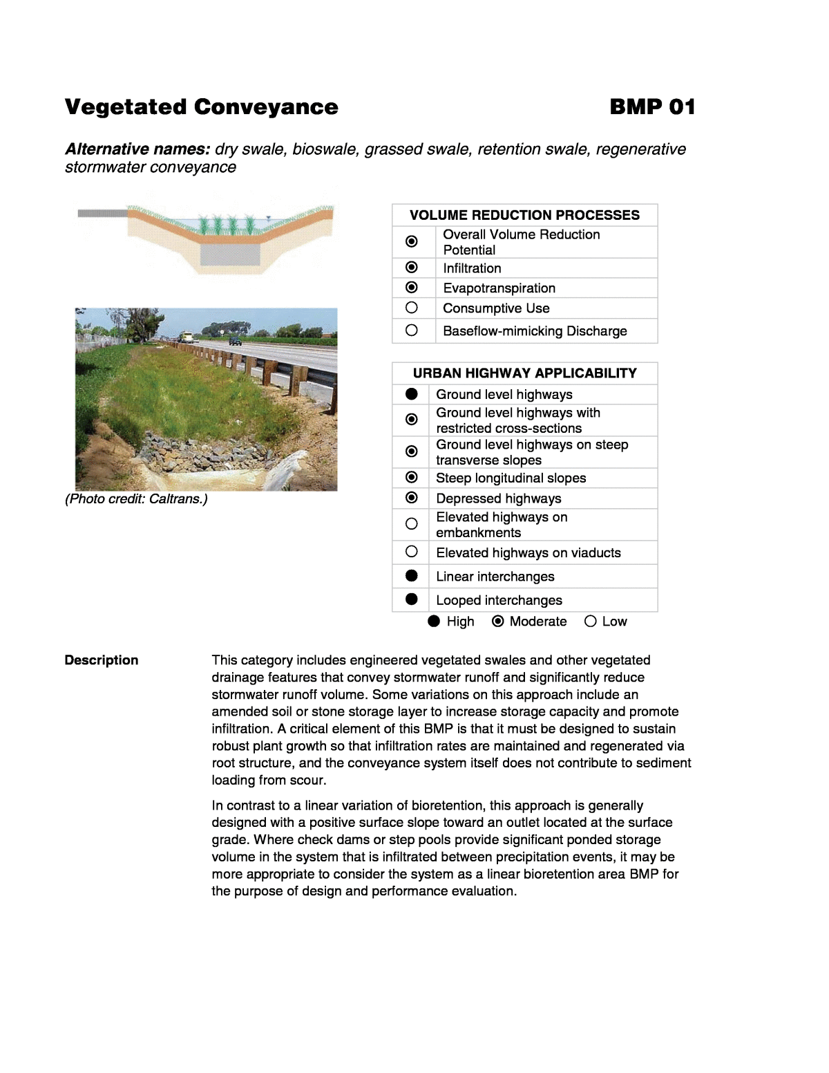
Vegetated Conveyance BMP 01 Alternative names: dry swale, bioswale, grassed swale, retention swale, regenerative stormwater conveyance (Photo credit: Caltrans.) VOLUME REDUCTION PROCESSES Overall Volume Reduction Potential Infiltration Evapotranspiration Consumptive Use Baseflow-mimicking Discharge URBAN HIGHWAY APPLICABILITY Ground level highways Ground level highways with restricted cross-sections Ground level highways on steep transverse slopes Steep longitudinal slopes Depressed highways Elevated highways on embankments Elevated highways on viaducts Linear interchanges Looped interchanges High Moderate Low Description This category includes engineered vegetated swales and other vegetated drainage features that convey stormwater runoff and significantly reduce stormwater runoff volume. Some variations on this approach include an amended soil or stone storage layer to increase storage capacity and promote infiltration. A critical element of this BMP is that it must be designed to sustain robust plant growth so that infiltration rates are maintained and regenerated via root structure, and the conveyance system itself does not contribute to sediment loading from scour. In contrast to a linear variation of bioretention, this approach is generally designed with a positive surface slope toward an outlet located at the surface grade. Where check dams or step pools provide significant ponded storage volume in the system that is infiltrated between precipitation events, it may be more appropriate to consider the system as a linear bioretention area BMP for the purpose of design and performance evaluation.
Volume Reduction Processes and Performance Factors Volume reduction is achieved through infiltration and evapotranspiration (ET). Volume reduction can be enhanced by including a stone or amended soil storage layer, providing shallow retention in the conveyance, and using a broader, flatter cross section. Soil infiltration rates, longitudinal slopes, and the relative ratio of BMP bottom area to tributary area are believed to be the most important key factors in volume reduction effectiveness. General DOT Experience In many cases, vegetated conveyances may be a standard highway design feature that would be installed regardless of water quality and volume reduction benefits. Therefore, these features can be used at very low incremental costs (for example, some minor additional bottom width may be what is needed to achieve volume reduction goals). In addition to a standard conveyance feature in many highway systems, vegetated conveyances have been implemented by DOTs to achieve both water quality treatment benefits and volume reductions of highway runoff. A review of volumetric measurements from swale studies in the International BMP Database shows moderate volume reduction on average (Geosyntec and Wright Water Engineers 2011) . Applicability and Limitations Site and Watershed Considerations Vegetated conveyances are suitable for most soil types. Soil infiltration rates will determine whether the swale can be designed to achieve significant infiltration or will serve primarily as conveyance with incidental volume reduction. Longitudinal slopes must be positive but not too steep (typically 1% to 6%) in order to provide positive drainage but to avoid the creation of high velocity flows that result in erosion. Check dams can allow the use of swales on somewhat steeper slopes (about 4% or over). Vegetated conveyances are relatively narrow and linear in profile, which allows them to fit into constrained spaces. They are suitable for use on shoulders and in medians, and compatible with general highway design and maintenance. Geotechnical Considerations Vegetated conveyances must be located a sufficient distance from the roadway so that infiltration will not compromise its structural integrity, Vegetated conveyances are a standard design feature in ground level highway types; they should not pose significant incremental geotechnical risks. Use of vegetated conveyances along steep transverse slopes may require enhanced protection of slope integrity. Groundwater Quality and Water Balance Considerations Vegetated conveyance does not generally pose elevated risks to groundwater quality or water balance. In areas with very high soil infiltration rates or shallow groundwater tables, captured stormwater may not be sufficiently treated prior to contact with groundwater. In these situations, designs may need Appendix A â Infiltration BMP Fact Sheets Vegetated Conveyance BMP 01 2
adjustment to enhance treatment and prevent groundwater contamination. Where soils allow high rates of infiltration, the use of vegetated conveyance may shift the water balance toward excess infiltration. Safety Considerations For vegetated conveyances to be located within the âclear zoneâ (typically in the range of 22 to 32 feet from driving lanes), vegetated conveyances should either be constructed with side slopes of 3H:1V or flatter, or a barrier should be used between the road and the conveyance (parallel to road). If a piped inlet is used, the pipe openings should be cut flush with the cross slope in order to reduce the potential that the pipe will be struck head-on by an errant vehicle. Pipes with diameters greater than 24 in. should be covered with traversable grates. Regional Applicability Vegetated conveyances are used across a broad range of climates. As a result, plants must be selected to be compatible with the local climate. In cold climates, use sod-forming grasses and cold climate-tolerant vegetation adjacent to roadway shoulders. Salt loadings in cold climates may also influence plant selection. Vegetative conveyances are more susceptible to clogging, as snow plowed alongside a roadway facility carries high sediment (road sand) and pollutant (road salt mixtures) loads. Vegetation, if not salt-tolerant, can be adversely affected. Sodium-based deicers have been shown to break down soil structure and potentially decrease infiltration rates. Irrigation is typically required for robust plant establishment, especially in arid climates. Highly arid climates without some irrigation may be more challenging. New Projects, Lane Additions, and Retrofits Vegetated conveyances are applicable and appealing retrofit options due to their low cost, effective treatment performance, and compatibility with highway design. Vegetated conveyances may have small incremental costs in new projects with sufficient ROW widths because grading can be balanced, and landscaping would otherwise be installed; incremental costs may be greater in lane additions and retrofits where a swale did not previously exist. Retrofitting an existing vegetated conveyance to improve volume reduction processes, such as by adding check dams, amending soils, or increasing plant density, can be an effective method of providing an pretreatment (e.g., addition of filtration media in the design) or Appendix A â Infiltration BMP Fact Sheets Vegetated Conveyance BMP 01 3
Appendix A â Infiltration BMP Fact Sheets Vegetated Conveyance BMP 01 4 when sediments and metals are the main target constituents; there is adequate space along the highway shoulder, along ramps, between sidewalks and roadways, and other landscaped areas; drainage patterns and topography are suitable; and there is safe maintenance access. Use in a Treatment Train Vegetated conveyances can be used to collect and convey water downgradient of a filter strip. Vegetated conveyances can be used to pretreat, achieve some volume losses and convey stormwater to centralized BMPs such as bioretention areas, infiltration trenches, or infiltration basins. BMP-Specific Maintenance Considerations They typically require maintenance activities similar to those already needed for maintenance of roadside vegetation and ditches. Proper function requires maintaining dense plant cover to prevent scouring. Patches of thin or missing vegetation should be repaired right away. Vegetation may need to be mowed or cut back regularly to maintain optimal plant height. Enhancements and Variations Add storage below the surface outlet. Vegetated conveyances may be underlain by storage areas composed of either stone and/or amended soils in order to increase storage capacity and promote infiltration and ET. Where this storage becomes the defining feature of the system, the BMP may be more appropriately categorized and designed as a linear bioretention area. Use check dams. In addition to helping slow and more evenly distribute flow, check dams can also prevent erosion (assuming that downstream of the check dam is protected). Check dams are used in vegetated conveyances to promote ponding and infiltration when the longitudinal slopes are large. It has also been found that retrofitting existing roadside ditches with check dams provides significant water quality benefits. Apply a compost amendment. Compost added to the soils of vegetated filtration systems can provide many benefits, the most significant being an increase in the retention and infiltration capacity of soils, which correspondingly increases pollutant load reductions. Compost amendments also increase the sorption sites, lower the bulk density, provide conditions conducive to healthy soil microbes, and promote growth and increased density of vegetation. Peat and compost should not be used as media as they retain water and freeze during the winter, and are thereby impermeable and ineffective. A slightly higher level of permeability should be used in colder climates to prevent frost heaving and encourage snowmelt runoff. incremental improvement in volume reduction for relatively minimal investment. Vegetated conveyances are applicable for ultra-urban highway retrofits
Stabilize the surface. A stabilization approach may be included in vegetated conveyances, such as reinforcement matting, to enable higher flows to be conveyed without scour. This has the benefit of reducing scour pathways where water moves more quickly with less potential for volume reduction. It also helps prevent sediment loading from scour. Create permanent pools for water quality improvement. Wetland-type systems, often referred to as wet swales, make use of check dams to create a series of impoundments where wetland conditions are allowed to develop. These systems can achieve high pollutant removal. However, they typically display low volume removal performance because their construction relies on impermeable soils, and thus ET is the primary mechanism for volume removal. Wetland-type systems can also provide areas for vector establishment and reproduction, resulting in the possible need for abatement measures. Cold climate applicability. In cold climates, these may be used as snow storage/melt areas. Salt-tolerant vegetation should be used, and length of growing season should be considered during construction of the BMP. It may take longer to establish vegetation, possibly two growing seasons, to achieve significant grass cover. Erosion control measures such as mats or blankets should be used to stabilize the slopes while the vegetative cover becomes established. The depth of soil media that serves as the planting bed must extend below the frost line to minimize the effects of freezing. Resilient Design Features The standard design of vegetated conveyances includes resiliency. The standard system design gravity drains from inlet to outlet, allowing water that does not infiltrate to discharge to the outlet. If check dams are included to promote infiltration, design them to allow the height to be adjusted if infiltration does not support the amount of infiltration intended. High flow through the system can cause damage and impair function. Designing off-line systems that only receive water quality storms can improve resilience by reducing the effects of high flow events. Seed/vegetation mixtures that will create a denser, deep-rooted vegetation mat will be more erosion resistant, enabling a more resilient surface during higher- intensity storms. Additional References for Design Information California Stormwater Quality Association. California Stormwater BMP Handbook: New Development and Redevelopment. TC-30, Vegetated Swale. 2003. Fact Sheet containing design guidance, construction and maintenance information for infiltration trenches, including costs. Available online at https://www.casqa.org/resources/bmp-handbooks/new-development- redevelopment-bmp-handbook. Slow the velocity of flow. Vegetated conveyances may be planted with densely growing native/non-invasive vegetation (turf not preferred) to slow flows, promote more infiltration, and allow greater volume reduction. Provide low flow outlet. Water can be held and released at a slow rate via a low flow outlet, such as a slotted weir, located at the downstream end of the system. This can provide detention and added volume reduction benefits. Appendix A â Infiltration BMP Fact Sheets Vegetated Conveyance BMP 01 5
structural stormwater management practices (SMPs) to meet water quality treatment goals, including feasibility and cold climate design guidance. There are highly detailed plan and profile figures for all types of BMPs under varying conditions, as well as a cold climate sizing example in Appendix I. The entire document can be downloaded from http://www.dec.ny.gov/docs/water_pdf/swdm2015entire.pdf. Oregon State University et al. 2006. NCHRP Report 565: Evaluation of Best Management Practices for Highway Runoff Control. Transportation Research Board of the National Academies, Washington, D.C. Manual intended to provide the highway engineer with selection guidance toward implementation of BMPs and LID facilities for control of stormwater quality in the highway environment. Includes detailed schematics and cost tables for different items in each BMP. http://www.trb.org/Publications/Blurbs/158397.aspx. Virginia Department of Conservation and Recreation. Virginia DCR Stormwater Design Specification No. 3: Grass Channel v.1.9. 2013. Fact sheet including design guidance, construction and feasibility. Excellent figures and schematics. http://chesapeakestormwater.net/category/publications/design-specifications/ Virginia Department of Conservation and Recreation. Virginia DCR Stormwater Design Specification No. 10: Dry Swale v.1.9. 2013. Fact sheet including design guidance, construction and feasibility. Excellent figures and schematics. http://chesapeakestormwater.net/category/publications/design-specifications/. Washington Department of Ecology. Stormwater Manual for Western Washington. BMP 2012. https://fortress.wa.gov/ecy/publications/summarypages/1210030.html. Washington State Department of Transportation, Highway Runoff Manual. 2014. Chapter 5 includes fact sheets for Stormwater BMPs. Available online at http://www.wsdot.wa.gov/Environment/WaterQuality/Runoff/HighwayRunoffManu al.htm. Center for Watershed Protectionâs Stormwater BMP Design Supplement for Cold Climates (Caraco and Claytor 1997). Includes recommended modifications for infiltration and other stormwater BMPs in cold climates. The document is available from the Center for Watershed Protection (CWP) at http://owl.cwp.org/mdocs-posts/caracod_sw_bmp_design_cold_climates/. New York State Stormwater Management Design Manual (2015). Chapter 6: Performance Criteria. Center for Watershed Protection, Ellicott City, Maryland. This chapter contains 66 pages on the performance criteria for five groups of Appendix A â Infiltration BMP Fact Sheets Vegetated Conveyance BMP 01 6
Appendix A â Infiltration BMP Fact Sheets Vegetated Conveyance BMP 01 7 Key Planning Level Design Parameters for Volume Reduction Conceptual Design Parameter Description Representative Range Bottom width The width of the level bottom of the conveyance feature. 1 to 10 feet Side slopes The steepness of the sides of the conveyance that connect the bottom of the swale to the ground surface. 3H:1V or flatter Longitudinal slope The slope of conveyance in the direction of flow. 1% to 5% Storage layer thickness The depth of the stone or amended soil storage reservoir. 0 to 24 inches (not required) Effective sump storage depth The effective depth of water retained (in media or stone pores, or behind check dams) that does not freely drain to surface drainage (if storage is in pores, the depth is the effective depth accounting for pore space). 0 to 6 inches (not required) Water quality flow depth The water level above the bottom of the swale during small storms that is considered to provide âtreatment.â 0 to 6 inches Maximum flow depth The maximum water level above the bottom of the swale under peak storm design conditions. 1 to 2 feet Design infiltration rates The rate at which water is assumed to infiltrate into the subsurface soils for design and benefits evaluation. This should be the rate of infiltration below the amended soil layer or stone reservoir. Can be used in any soil condition On-line versus off-line configuration Vegetated conveyance that is on-line is designed to provide conveyance for all storm events; treatment functions are considered to cease or be minimal when the water quality flow is exceeded. However, volume reduction would be expected to continue to occur at higher rates based upon higher head values. Vegetated conveyance that is off-line receives only water quality design flows; peak storm flows are bypassed around the system while treatment and volume reduction processes continue. Highway vegetated conveyance is typically on-line because of the challenge of providing flow splitter diversion at various diffuse locations Example Conceptual Design Schematics Figures 1, 2, 3, and 4 show cross-section view, longitudinal profile, plan view, and an example of swale adjacent to roadway environment, respectively.
Figure 1. Cross-section view. Figure 2. Longitudinal profile. Appendix A â Infiltration BMP Fact Sheets Vegetated Conveyance BMP 01 8
Figure 3. Plan view. Figure 4. Example of swale adjacent to roadway environment (from NCHRP Report 565). Appendix A â Infiltration BMP Fact Sheets Vegetated Conveyance BMP 01 9
Example O&M Activities and Frequencies Activity Frequency GENERAL INSPECTIONS Remove trash and debris Two times per year including before and after wet season.Repair eroded facility areas Inspect and maintain access roads Inspect and resolve areas of standing water Remove minor sediment in facility bottom Provide vector control if needed Identify any needed corrective maintenance that will require site-specific planning or design ROUTINE MAINTENANCE Vegetation In arid climates, irrigate as recommended by a landscape professional, typically for the first 3 years to establish vegetation As needed Remove undesirable vegetation Annually Repair areas of thin or missing vegetation Annually Repair areas of scour, rilling, or channelization Annually Inflow Outflow Structures Check energy dissipation function and add riprap Annually Inspect inlets and outlets and remove accumulated sediment if it impairs hydraulic function Annually CORRECTIVE (MAJOR) MAINTENANCE Regrade and replace top 3 to 6 inches of topsoil layer and accumulated sediment and replace vegetation Estimated every 10 years (highly site specific) Repair structural damage to inlets, outlets, and underdrain As needed Prepare documentation of issues and resolutions for review by appropriate parties Before major maintenance Document major maintenance activities; record modified O&M Plan and as- built plan set if needed After major maintenance Take photographs before and after from the same vantage point Before and after Appendix A â Infiltration BMP Fact Sheets Vegetated Conveyance BMP 01 10
Dispersion BMP 02 Alternative names: natural dispersion, engineered dispersion, vegetated filter strip, compost amended vegetated filter strip, vegetated buffer area Informal dispersion to median and shoulder, Interstate 8, San Diego, California, urban area. (Credit: Google.) VOLUME REDUCTION PROCESSES Overall Volume Reduction Potential Infiltration Evapotranspiration Consumptive Use Baseflow-mimicking Discharge URBAN HIGHWAY APPLICABILITY Ground level highways Ground level highways with restricted cross-sections Ground level highways on steep transverse slopes Steep longitudinal slopes Depressed highways Elevated highways on embankments Elevated highways on viaducts Linear interchanges Looped interchanges High Moderate Low Description This category consists of the dispersion of runoff toward existing and/or restored pervious areas for reducing stormwater runoff volumes and achieving incidental treatment. It also includes road shoulders amended with compost and additional materials such as sand (if needed), designed to convey runoff as sheet flow over the surface or as shallow subsurface flow through amended soil layers. Dispersion reduces overall runoff volume by means of infiltration and ET. Volume reduction performance can be improved with the use of flow spreaders, soil amendments, and re-vegetation. A critical element to this BMP is ensuring that dispersion areas support robust vegetative growth to stabilize the surface and maintain good infiltration rates. Dispersion involves making use of existing design features such as vegetated medians, road shoulders, and buffers by routing water to these areas and/or improving their ability to accept water. For example, dispersion could include removing curb/gutter sections where this would enable the flow of water to a pervious area that is acceptable. Additionally, the benefits of an existing dispersion pathway can be enhanced through minor investments in modification of drainage patterns (e.g., improve uniformity of dispersion) and/or restoration of degraded areas. In many cases, the buffers and medians that would otherwise be
treatment benefits with very limited incremental cost. Volume Reduction Processes and Performance Factors Volume reduction is achieved through infiltration and ET. The quantity of volume reduction expected is dependent on the siteâs soils, topography and hydraulic characteristics (e.g., storage capacity, hydraulic retention time, etc.). Highly permeable soils have the capacity to infiltrate large volumes of stormwater and small depressions can capture and store stormwater runoff, which can then infiltrate, evaporate, or be consumed by vegetation between events. Because of the extensive nature (i.e., larger footprint) of dispersion-type approaches, it is the ET fraction of the water balance that tends to be significant. General DOT Experience Dispersion is commonly used for management of stormwater runoff from highways, particularly in more rural areas. The approach of allowing water to sheet flow over shoulders tends to be compatible with standard highway designs where shallow gradient medians and shoulders would otherwise be constructed. Benefits of dispersion on reducing runoff volumes and treating stormwater are increasingly recognized by DOTs. While DOTs made these land and design investments for transportation and safety purposes, they also provide water quality and volume reduction benefits. For swales and filter strips, water quality benefits can effectively be considered free when compared with conventional drainage systems, and when the maintenance is performed by the property owner. Additionally, by amending roadway shoulders with compost and other materials, there is potential to improve the ability of existing road shoulders to reduce runoff volumes and provide treatment, thereby allowing incremental benefit to be claimed for relatively low investment. In more constrained situations, DOTs have found that current design standards for highway construction do not always align with applicable design guidelines for filter strips and dispersion. For example, WSDOT (2014) notes that its highway runoff manual recommends a maximum side-slope of 4H:1V for dispersion practices while most roadway embankments fall between 2:1 to 6:1 where space and or topography constrain designs. For steeper slopes, specific attention should be given to effective spreading of flow and maintaining sheet flow. Alternatively, a more engineered approach, such as a Media Filter Drain (see BMP 03), may be more appropriate for steeper shoulders than simple dispersion over a naturally vegetated area. DOTs have also found that vegetative cover and regenerative growth are critical to maintaining long-term infiltration rates. A monitoring case study on vegetated filter strips in Texas by Walsh et al. (1998) also highlights the importance of infiltration capacity to vegetative cover with more ânaturalâ and wooded areas having greater capacity to infiltrate runoff. Studies of filter strips reported to the International Stormwater BMP Databases, mostly in California, showed moderate levels of volume reduction (Geosyntec and Wright Water Engineers 2011). In addition, DOTs have considerable experience using compost amendment of road shoulders as an initial treatment following construction to promote stabilization and vegetation growth (U.S. EPA 2013; Connecticut DOT 1999; Black 1999; Caltrans 2010; Glanville et al. 2003). constructed as part of standard roadway design can provide volume reduction and Appendix A â Infiltration BMP Fact Sheets Dispersion BMP 02 2
Applicability and Limitations Site and Watershed Considerations Dispersion to areas with high infiltration rates will result in higher rates of volume reduction. Dispersion is suitable for most soil types. Where soils are silty or clayey, a sand or compost amendment may be needed to provide adequate long- term permeability for water to flow into the soil. Dispersion practices rely on sheet flow over a relatively large distance (typically at least 10 to 15 feet) to achieve significant volume reduction. They may therefore not be suitable for roads with very restricted ROWs. Embankment slopes should provide positive drainage away from the roadway but not be steeper than approximately 6H:1V. Longitudinal slopes must not be too steep (typically less than 5%) in order to allow more uniform dispersion and avoid the creation of high velocity flows that may result in erosion. Large drainage areas (e.g., roadways wider than approximately 2 to 3 lanes) may increase the potential for flow to concentrate during high intensity storm events and produce high velocity flows with the potential to create erosive conditions. Because of the importance of maintaining sheet flow into dispersion areas, site-specific calculations are recommended to account for local precipitation intensities, design geometries, and soil conditions. Sheet flow conditions can be encouraged using a gravel area between the road shoulder and the dispersion area (see schematic design of BMP 03: Media Filter Drain). Urban highways are not typically surrounded by undeveloped area; however, patches of natural vegetation sometimes exist, particularly in the centers of interchanges and in wide spots in the ROW. Therefore, the opportunity for dispersion is dependent on specific site conditions and available vegetation in the vicinity of the project. The dispersion area should be owned by the project owner or located in a permanent easement dedicated for water quality purposes. Geotechnical Considerations Generally, dispersion poses relatively limited incremental risk for slope stability and settlement, because standard design practices help mitigate risks, including (1) accounting for surficial wetting in geotechnical calculations, (2) design of near-highway areas with positive drainage away from the highway, and (3) design features to prevent surficial erosion (e.g., flow spreading, shallow slopes, vegetated cover). The most significant geotechnical issue is potential for rill erosion to form and progress along the roadside shoulder if soil is not stabilized and/or concentrated flow paths develop. Where a design modification will result in significant infiltration occurring in a concentrated area, such as ponding more than a few inches deep, analysis of slope stability and other geotechnical factors should be considered within the vicinity of this area. Infiltration BMP Fact Sheets Dispersion BMP 02 3 Appendix A â
recommended upper limits on embankment slope. Groundwater Quality and Water Balance Considerations Because water disperses in shallow depths over a broad area, dispersion poses relatively low risk of groundwater quality impacts and water balance impacts. Risks may be elevated in areas with very high soil infiltration rates or shallow groundwater tables. In these situations, soil amendments may be warranted to provide better treatment of infiltrated water and better soil water retention. Safety Considerations Dispersion areas should be free from trees or other obstacles within the clear zone (typically in the range of 22 to 32 feet from driving lanes). Cross-slopes within the clear zone should not exceed 4H:1V. If maintaining these conditions is not possible, a barrier should be placed between the road and the dispersion area, parallel to vehicular travel. Soil amendments that are used within the clear zone to improve permeability and/or vegetation growth should be selected to provide a finished surface that is adequately stable for errant vehicle recovery. If a vegetated conveyance is used to convey water to dispersion areas, it should be constructed with side slopes of 3H:1V or flatter. Any piped inlets should have openings cut flush with the slope in order to reduce the potential that the pipe will snag an errant vehicle. Pipes with diameters greater than 24 inches should be covered with traversable grates. Regional Applicability Dispersion can be applied across a broad range of climates but will differ in nature in terms of vegetation. Dispersion approaches require dense and robust vegetation for proper function. In arid regions, drought tolerant species should be selected to minimize irrigation needs and reduce the potential for seasonal die-off. In cold climates where salt is utilized, vegetation should be selected to be tolerant of elevated salt levels. Vegetative conveyances are more susceptible to clogging, as snow plowed alongside a roadway facility carries high sediment (road sand) and pollutant (road salt mixtures) loads. Vegetation, if not salt-tolerant, can be adversely affected. Sodium-based deicers have been shown to break down soil structure and potentially decrease infiltration rates. Regional rainfall intensities and characteristic patterns should be considered during the design process to ensure road shoulder sections will not be hydraulically overloaded and sheet flow conditions will be maintained to the extent practicable. Where adjacent natural land covers are highly erosive (such as arid areas), the elevated potential for rill erosion may present challenges for the application of this approach. Long-term stability and reduction in erosive flow potential can be enhanced with robust plant growth, effective dispersion, and adhering to Dispersion BMP 02 4 Appendix A â Infiltration BMP Fact Sheets
into the project as design features. Retrofit of dispersion may include modifying the current drainage pathway, such as by removing a curb and gutter to allow dispersion to occur or providing more uniform dispersion, and/or enhancing the dispersion area, such as by amending, decompaction, leveling, and/or vegetating the area. In either case, an incremental benefit in treatment and volume reduction capabilities can be claimed through this retrofit. The feasibility of retrofitting an existing embankment would be influenced by the amount of import/export of material that would be needed (i.e., soil amendment versus soil replacement). Use in a Treatment Train Vegetated conveyance can be used to convey runoff to a dispersion area. Dispersion can be used to pretreat and convey stormwater to secondary BMPs. Enhancements and Variations Slow the velocity of flow. Areas of dispersion may be planted with densely growing native/non-invasive vegetation to slow flows and allow greater volume reduction. Minor re-grading to leveling the surface can also help slow and more evenly distribute flow. Check dams and berms may be constructed on steeper slopes to slow flows and create small ponding areas to encourage infiltration and treatment. Spread out the flow equally. Equal distribution of flows can help ensure that all the available area is being utilized, thereby improving both volume reduction and treatment capacity. Equal dispersion can be achieved by leveling the surface and using shoulder treatments such as stone spreading trenches that promote more even inflow. Maintenance may be needed to avoid the development of concentrated flow pathways. Landscaping/restoration. Planting and/or restoring areas of dispersion can be used to establish and promote higher and stable infiltration rates while also providing increased roughness to slow overland flows. Establishing and retaining dense/natural vegetation will help ensure that infiltration rates are maintained over the long term. Vegetated conveyance dispersion area. Where road shoulders are not conducive to overland flow or the dispersion area is a distance from the roadway, vegetated conveyance can be used to convey flow to the dispersion area. Improve infiltration rates. Where site soils are silty or clayey, sand may be incorporated into the soil along with compost to improve infiltration and flow through the media. Where site soils are plastic and would not sustain long-term permeability, the topsoil layer can be removed and replaced with a compostâsand mixture. Resilient Design Features The standard design of dispersion has resiliency included in the design because this BMP does not rely on a minimum infiltration rate to function properly. New Projects, Lane Additions, and Retrofits Dispersion may have small incremental costs in new projects because suitable areas such as vegetated shoulders are often already incorporated Dispersion BMP 02 5 Appendix A â Infiltration BMP Fact Sheets
within the dispersion area. Absorption capacity can be gained by using compost- amended soils to disperse and absorb contributing flows to the dispersion area. This will help ensure the dispersion area has the capacity and ability to infiltrate surface runoff. Natural dispersion areas may initially cost as much as other constructed BMPs (ponds or vaults), because ROW or easements often need to be purchased, but long-term maintenance costs are lower because water is able to spread and therefore has low risk of clogging or erosion. A key cause of failure is rill erosion or channelization in the dispersion area. Emphasizing property design and maintenance of level spreader can reduce the risk of failures to the dispersion area/filter strip. The dispersion area may be amended with compost material to increase infiltration rates, provide pretreatment, and further enhance filtration or groundwater recharge Dispersion BMP 02 6 Appendix A â Infiltration BMP Fact Sheets
Additional References California Stormwater Quality Association. California Stormwater BMP Handbook: New Development and Redevelopment. TC-31, Vegetated Buffer Strip. 2003. Fact sheet containing design guidance, construction and maintenance information for infiltration trenches including costs. Available online at http://www.cabmphandbooks.com/Development.asp. Virginia Department of Conservation and Recreation. Virginia DCR Stormwater Design Specification No. 2: Sheet Flow to a Vegetated Filter Strip or Conserved Open Space v.1.9. 2011. Fact sheet on infiltration practices including design guidance, construction and feasibility. Excellent figures and schematics. Available online at http://chesapeakestormwater.net/category/publications/design- specifications/. Virginia Department of Conservation and Recreation. Virginia DCR Stormwater Design Specification No. 4: Soil Compost Amendment v.1.9. 2011. http://chesapeakestormwater.net/category/publications/design-specifications/. Virginia Department of Conservation and Recreation. Virginia DCR Stormwater Design Specification No. 2: Sheet Flow to a Vegetated Filter Strip or Conserved Open Space v.1.9. 2011. http://chesapeakestormwater.net/category/publications/design-specifications/. Washington State Department of Transportation, Highway Runoff Manual. 2014. http://www.wsdot.wa.gov/Publications/Manuals/M31-16.htm. Washington Department of Ecology. Stormwater Manual for Western Washington. BMP FC.01: Natural Dispersion. 2012. https://fortress.wa.gov/ecy/publications/summarypages/1210030.html. Washington Department of Ecology. Stormwater Manual for Western Washington. BMP FC.02: Engineered Dispersion. 2012. https://fortress.wa.gov/ecy/publications/summarypages/1210030.html. Washington Department of Ecology. Stormwater Manual for Western Washington. BMP RT.02: Vegetated Filter Strip. 2012. https://fortress.wa.gov/ecy/publications/summarypages/1210030.html. Dispersion BMP 02 7 Appendix A â Infiltration BMP Fact Sheets
Key Planning Level Design Parameters for Volume Reduction Conceptual Design Parameter Description Representative Range Footprint area The area that will receive stormwater. No practical limit, larger areas will tend to provide greater volume reduction. Contributing area The area draining to the footprint area. No practical limit; however, inflows should be distributed as sheet flow or multiple diffuse inflow points to avoid concentrating flows. Infiltration rate The infiltration rate of the underlying soils within the dispersion area. Any. Higher infiltration rates will achieve greater volume reduction. Width of amended shoulder The width of the shoulder in the direction of flow (i.e., perpendicular to the roadway edge). 10 to 15 feet typical; however, there is no practical limitâlarger areas will tend to provide greater volume reduction. Cross slope The final grade of the road shoulder surface (perpendicular to the roadway edge) as a ratio of vertical distance to horizontal distance (i.e., 12%, or 8H:1V). 4H:1V or flatter Amendment thickness The depth to which amendments are incorporated into the soil. 6 to 12 inches Effective depth of depression storage Including pore storage added through soil decompaction/amendment and/or naturally occurring depressions where ponding is expected (expressed as depth). 1 to 6 inches Example Conceptual Design Schematics Figures 1 and 2 show cross-section and plan views, respectively. Figures 3 and 4 show natural or engineered dispersion without a gravel level spreader and with a gravel level spreader, respectively. Dispersion BMP 02 8 Appendix A â Infiltration BMP Fact Sheets
Figure 1. Cross-section view. Figure 2. Plan view. Dispersion BMP 02 9 Appendix A â Infiltration BMP Fact Sheets
Figure 3. Natural or engineered dispersion without a gravel level spreader (WSDOT 2014). Figure 4. Natural or engineered dispersion with a gravel level spreader (WSDOT 2014). Dispersion BMP 02 10 Appendix A â Infiltration BMP Fact Sheets
Example O&M Activities and Frequencies Activity Frequency GENERAL INSPECTIONS Identify any needed corrective maintenance that will require site-specific planning or design Annually Inspect function of level spreader Inspect degree of degree of channelization in filter strip Inspect degree of undesirable vegetation (weeds) ROUTINE MAINTENANCE Vegetation In arid climates, irrigate as recommended by a landscape professional, typically for the first 3 years to establish vegetation As needed Reseed areas of thin or missing vegetation Annually Repair eroded areas Annually Level Spreader Fill areas of level spreader that appear to be channelized or sedimented to restore function Annually Regrade road shoulder and augment gravel periodically to restore level spreader 3 to 5 years CORRECTIVE (MAJOR) MAINTENANCE Decompact/aerate filter strip to at least a 6-inch depth and reseed to maintain porosity and robust vegetation replace vegetation Estimated every 10 to 15 years (highly site specific) Regrade to correct channelization. Decompact, amend, and reseed filter strip to restore. Estimated every 30 years (highly site specific) Prepare documentation of issues and resolutions for review by appropriate parties Before major maintenance Document major maintenance activities; record modified O&M Plan and as- built plan set if needed After major maintenance Take photographs before and after from the same vantage point Before and after Dispersion BMP 02 11 Appendix A â Infiltration BMP Fact Sheets
Media Filter Drain BMP 03 Alternative names: formerly known as "Ecology Embankment" Media Filter Drain along SR 14in Clark County, Washington. (Source: WSDOT 2011.) VOLUME REDUCTION PROCESSES Overall Volume Reduction Potential Infiltration Evapotranspiration Consumptive Use Baseflow-mimicking Discharge URBAN HIGHWAY APPLICABILITY Ground level highways Ground level highways with restricted cross-sections Ground level highways on steep transverse slopes Steep longitudinal slopes Depressed highways Elevated highways on embankments Elevated highways on viaducts Linear interchanges Looped interchanges High Moderate Low Description This BMP consists of a stone vegetation-free zone, a grass strip, a media filter storage reservoir filled with specialized media, and a conveyance system for flows leaving the reservoir. This conveyance system usually consists of a gravel-filled underdrain trench or a layer of crushed surfacing base course. The stone vegetation- free zone produces sheet flow, which is pretreated as it flows across the grass strip, and is then captured by the storage reservoir, where it infiltrates into the subsoil or is discharged through the underdrain. This BMP is typically installed between the road surface and a ditch or other conveyance located downslope. While this approach shares many similarities to BMP 02 Dispersion, its engineering design features allow it to be sited in more constrained areas and on steeper cross slopes where dispersion would not be as viable. Volume Reduction Processes and Performance Factors Runoff volume is reduced through infiltration and ET. Water is treated as it moves over the grass strip and through the media within the reservoir. The relative volume reduction potential is a function of the underlying infiltration rate and the local wet- season ET rates. The primary flow pathway through the media tends to provide flow attenuation that may partially mimic baseflow in some environments.
General DOT Experience This BMP is widely used by WSDOT and was formerly referred to as an âEcology Embankment.â A technology evaluation report prepared for âEcology Embankmentsâ for WSDOT shows both significant volume and load reductions in some cases up to 100% (Herrera Environmental Consultants 2006). Some design standards for filter strips employed by other DOTs include elements that resemble the media filter drain. These are applicable for siting linearly in the median and ROWs on most shoulder slopes. Limiting their use to treatment of runoff from impervious areas only will maximize their life. Applicability and Limitations Site and Watershed Considerations Media filter drains are suitable for most soil types. Where soils are silty or clayey, an underdrain may be required to convey excess runoff. Media filter drains are one of the few BMPs that can be constructed directly on roadside embankments up to a 4H:1V slope and incorporated into conventional highway design. They may be quite useful in situations where roadway embankments are the only vegetated area within the ROW. Media filter drains work best on low to moderate longitudinal slopes (less than 5%). Greater longitudinal slopes present greater difficulties for evenly spreading water. Large drainage areas (e.g., wider roadways) may increase the potential for flow to concentrate during high intensity storm events and produce high velocity flows with the potential to create erosive conditions. Sheet flow conditions can be encouraged using a dispersion trench or other approach intended to spread and slow flows. Media filter drains can be sited in confined ROWs, on shoulders, and in narrow medians, and are suitable in many confined urban highway settings. Geotechnical Considerations Generally, use of media filter drains introduces relatively limited incremental risk for slope stability and settlement because standard highway design practices help mitigate risks, including (1) accounting for surficial wetting in geotechnical calculations, (2) design of shoulder with positive drainage away from the highway, and (3) design features to prevent surficial erosion (e.g., flow spreading, shallow slopes, vegetated cover). Site specific infiltration rates and physical makeup of the soil (i.e., soil class) will determine what design features are needed for effective volume reduction and treatment. Long-term stability and reduction in erosive flow potential can be enhanced with robust plant growth, effective dispersion, and adhering to recommended upper limits on embankment slope. Groundwater Quality and Water Balance Considerations Due to its extensive nature and the degree of treatment provided by the media, this BMP poses relatively low risk of groundwater quality impacts and water balance impacts. Media Filter Drain BMP 03 2 Appendix A â Infiltration BMP Fact Sheets
Risks of water balance impacts may be elevated in areas with very high soil infiltration rates and hydrogeologic conditions that are sensitive to increases in infiltration volume. Safety Considerations Media filter drains are usually located within the clear zone, but their low cross-slopes and lack of fixed obstacles make them safely traversable, and no barriers are required. Regional Applicability Media filter drains require dense and robust vegetation for proper function. In arid regions, drought tolerant species should be selected to minimize irrigation needs and reduce the potential for seasonal die-off. If a regionally adapted species cannot be identified to provide surface stabilization without irrigation, then this BMP may not be applicable. In cold climates where salt is utilized, vegetation should be selected to be tolerant of elevated salt levels. Regional rainfall intensities and characteristic patterns should be considered during the design process to ensure road shoulder sections will not be hydraulically overloaded and sheet flow conditions will be maintained to the extent practicable. New Projects, Lane Additions, and Retrofits Media filter drains can be incorporated into conventional highway design or can be constructed on existing roadside embankments. Retrofitting an existing embankment would involve export of existing soils, installation of an underdrain, and import of the specialized media filter mix. As such, retrofits are expected to be more expensive than when constructed as part of a new project or lane addition. Use in a Treatment Train Media filter drains can be used to pretreat and convey stormwater to secondary BMPs. Media Filter Drain BMP 03 3 Appendix A â Infiltration BMP Fact Sheets
Enhancements and Variations Apply on internal as well as external embankments. If the roadway has a median, then a dual media filter drain design can be used to capture runoff from both of the internal embankments. Use an underdrain to improve hydraulic conveyance where infiltration rates are limited. Where site soils are silty or clayey, an underdrain may be used to improve hydraulic conveyance of stormwater through the media. Treated runoff would be conveyed to a downstream BMP or stormwater outfall. Increase footprint area at intersections and wider portion of ROW. Drainage can be routed to media filter drains with broader footprints in the open space formed by intersections and at wider sections of the ROW to help increase the dispersion area that is provided. Use soil amendments. Media amendments to sand filters or specially designed media mixtures can be used to improve treatment performance over sand media alone. For example, the media mix in WSDOT media filter drains includes crushed stone, dolomite and gypsum for alkalinity and ion exchange capacity to promote the precipitation and exchange of heavy metals, and perlite for moisture retention. Apply outlet control. Use an orifice outlet to regulate flows through the gravity drainage filtration system, rather than use the media properties to control the hydraulic design. A primary discharge orifice can be placed near the top of the media bed, sized and configured to pass the design storm flows under saturated media conditions. A low flow orifice can be placed below the media bottom, sized and configured to restrict flows and encourage filling for small storm event flows and allow for complete drainage of the media bed within a specified drain time following a storm event. Use filter fabric. If a filter is used to treat runoff from a roadway that is sanded, there is higher potential for clogging from the sand in the runoff. To prevent clogging of the underdrain, a permeable filter fabric should be placed between the gravel layer and the filter media, as shown on Figure 3. The purpose of filter fabric is to prevent sand from infiltrating into the gravel layer and the underdrain piping. Resilient Design Features Typical guidance calls for configuring a media filter drain with an underdrain as a protective measure to ensure free flow through the media filter drain to prevent prolonged ponding, and to discharge excess water in marginal infiltration conditions. This provides resiliency. If infiltration is more clearly feasible, a capped underdrain could be used, and only opened if infiltration rates are not adequate. In areas where there is a narrow roadway shoulder that does not allow enough room for a vehicle to fully stop or park, place the media filter drain farther down the embankment slope, this will reduce the amount of rutting in the media filter drain and decrease overall maintenance repairs. In cold climates, the underdrain should be extended below the frost line and oversized to prevent freezing of the underdrain itself or the filter media. Media Filter Drain BMP 03 4 Appendix A â Infiltration BMP Fact Sheets
Additional References Washington State Department of Transportation, Highway Runoff Manual. 2014. Chapter 5 includes fact sheets for Stormwater BMPs. Available online at http://www.wsdot.wa.gov/Environment/WaterQuality/Runoff/ HighwayRunoffManual.htm. Washington Department of Ecology. Stormwater Manual for Western Washington. BMP RT.07: Media Filter Drain. 2012. Available online at https://fortress.wa.gov/ecy/publications/summarypages/1210030.html. Herrera Environmental Consultants (2006). Technology Evaluation and Engineering Report, WSDOT Ecology Embankment, Prepared for Washington State Department of Transportation. July 2006. http://www.wsdot.wa.gov/NR/rdonlyres/3D73CD62- 6F99-45DD-B004-D7B7B4796C2E/0/EcologyEmbankmentTEER.pdf. Key Planning Level Design Parameters for Volume Reduction Conceptual Design Parameter Description Representative Range Footprint area The area covered by the surface of the media filter drain. Any Maximum flow path The maximum distance runoff should travel as sheet flow to the media filter drain (i.e., maximum width of travel lanes). Up to 150 feet Tributary area ratio The footprint of the media filter drain as a fraction of the total tributary area (including the media filter drain itself). Up to 10:1 may be typical of urban roadways Cross slope The slope of the embankment perpendicular to the roadway. 4H:1V or flatter Longitudinal slope The slope running parallel to the roadway. Typically limited to less than 5% Stone strip width The width of the stone strip used to create sheet flow. 1 to 3 feet Grass strip width The width of the grass strip used for pretreatment. 3 to 5 feet Media filter depth The depth of the filter media storage reservoir. 12 inches Design soil infiltration rate The rate at which water is assumed to infiltrate into the subsurface soils for the purpose of design and benefits evaluation. This should be the rate of infiltration below the amended soil layer or stone reservoir. Any Example Conceptual Design Schematic Figures 1, 2, and 3 show cross-section view, plan view, and components of a media filter drain, respectively. Media Filter Drain BMP 03 5 Appendix A â Infiltration BMP Fact Sheets
Figure 1. Cross-section view. Media Filter Drain BMP 03 6 Appendix A â Infiltration BMP Fact Sheets
Figure 2. Plan view. Figure 3. Components of a media filter drain. Media Filter Drain BMP 03 7 Appendix A â Infiltration BMP Fact Sheets
Activity Frequency GENERAL INSPECTIONS Identify any needed corrective maintenance that will require site-specific planning or design Annually Inspect function of level spreader Inspect degree of degree of channelization in filter strip or media filter drain Inspect degree of undesirable vegetation (weeds) ROUTINE MAINTENANCE Vegetation-Free Zone (rock level spreader) Level areas that are channelized and interfere with sheet flow As needed Remove accumulated sediment that interferes with sheet flow Grass Filter In arid climates, irrigate as recommended by a landscape professional, typically for the first 3 years to establish vegetation As needed Reseed areas of thin or missing vegetation As needed Repair eroded areas or accumulated sediment that interferes with sheet flow As needed Mow vegetation greater than about 10 inches As needed Media Filter Drain Repair eroded areas by leveling surface of media filter As needed Replenish media if spots of scour have occurred (and remedy source of scour) As needed CORRECTIVE (MAJOR) MAINTENANCE Replace filter media Estimated every 10 years Replace underdrain if damaged or clogged As needed Prepare documentation of issues and resolutions for review by appropriate parties Before major maintenance Document major maintenance activities; record modified O&M Plan and as- built plan set if needed After major maintenance Take photographs before and after from the same vantage point Before and after Example O&M Activities and Frequencies Media Filter Drain BMP 03 8 Appendix A â Infiltration BMP Fact Sheets
Permeable Shoulders BMP 04 Alternative names: permeable shoulders with stone reservoirs, permeable gutters VOLUME REDUCTION PROCESSES Overall Volume Reduction Potential Infiltration Evapotranspiration Consumptive Use Baseflow-mimicking Discharge URBAN HIGHWAY APPLICABILITY Ground level highways Ground level highways with restricted cross-sections Ground level highways on steep transverse slopes Steep longitudinal slopes Depressed highways Elevated highways on embankments Elevated highways on viaducts Linear interchanges Looped interchanges High Moderate Low Description This BMP includes use of a permeable pavement surface course (typically permeable asphalt or concrete) along the shoulders of a roadway, underlain by a stone reservoir. Precipitation falling on the permeable pavement as well as stormwater flowing onto permeable pavement from adjacent travel lanes infiltrates through the permeable pavement top course into the stone reservoir, from which it infiltrates into the subsoil or is discharged through an underdrain and outlet control structure. Through the use of an underdrain and flow control outlet to augment infiltration capacity, permeable shoulders can be applied in a wide range of soil conditions. This BMP is most effective for volume reduction when soils are suitable for infiltration and outlet control can be provided to mimic baseflow discharge. In contrast to permeable pavements applied in parking lots, parking strips, streets, and walkways in other land uses, permeable road shoulders tend to be characterized by a higher ratio of tributary impervious area (travel lanes) to pervious area (shoulders). Additionally, more stringent requirements may apply to the structural design and subbase drainage design than apply to permeable pavements in other land uses. These BMPs can have extreme limitations, associated with studded tires, traction sand, longitudinal slopes, and cost to retrofit in existing roads. (Photo credit: Pike Industries.)
Volume Reduction Processes and Performance Factors Volume reduction is achieved primarily through infiltration. The degree of allowable infiltration is a function of soil infiltration rates (after compaction), degree of subbase wetting that is allowable in design, and the presence of other factors such as slope stability or utility issues. Where infiltration is limited due to soil conditions or other factors, permeable pavement systems can be enhanced with underdrains to provide flow control and augment infiltration discharge. When designed with adequate storage, permeable pavement systems can provide temporary detention of storm flows and controlled release, discharging flows at rates similar to natural base flows with the use of underdrains and flow controls. General DOT Experience Permeable pavement shoulders are increasingly being considered for implementation within the highway environment. However, their application remains very limited. Some DOTs have found open graded friction course to be an effective method to improve roadway safety (by reducing surface flow and splash/spray effects). Permeable shoulders would have these benefits and also provide volume reduction. Runoff reduction estimates derived from various case studies summarized by Hirschman et al. (2008) range from 45% when incorporating underdrains to 75% when not using underdrains and assuming adequate pretreatment and soil testing. In some studies volume reductions ranged from 94% to 100% (Van Seters et al. 2008; Legret and Colandini 1999; Bean et al. 2007; Collins et al. 2008; and Brattebo and Booth 2003). The University of California Pavement Research Center (UCPRC) concluded that permeable shoulders are technically feasible and economically advantageous compared with other BMPs and can be used where infiltration rates are as low as 0.014 inches per hour (Chai et al. 2012). Permeable shoulders can have extreme limitations in cold climates as a result of studded tires and traction sand. They are also not feasible on roadways with longitudinal slope greater than about 1% and can be very expensive to retrofit into existing roadways. Guidance on design, construction, and maintenance of permeable shoulders with stone reservoirs was conducted as part of NCHRP Project No. 25-25/Task 82 (Hein et al. 2013). A review of permeable shoulder applicability and limitations is found in NCHRP Report 802: Volume Reduction of Highway Runoff in Urban AreasâGuidance Manual. Applicability and Limitations Site and Watershed Considerations Permeable pavements are better suited to areas with granular soils, such that infiltration rates are relatively high and subgrade strength is not significantly diminished by wetting. Roadways with flat to shallow longitudinal slopes (less than 1%) are suitable for permeable shoulders, because the volume of the storage reservoir is best utilized. Steeper longitudinal slopes require cutoff walls and intermediate outlet points, and there is greater potential for water to flow below the roadway. This can greatly reduce feasibility. Permeable pavements can be used on road shoulders and in medians. They can be useful in constrained areas where there is insufficient space for vegetated BMPs. A fully-lined version of permeable pavement with an underdrain could be used on elevated highways or viaducts. Stormwater could be stored within the stone Permeable Shoulders BMP 04 2 Appendix A â Infiltration BMP Fact Sheets
reservoir and would then be discharged via underdrains or routed to additional BMPs. Current applicability of permeable pavements to main roadway sections is not well established relative to structural design requirements, top course durability, and safety. Research is ongoing. Geotechnical and Pavement Design Considerations The overflow elevation from the storage reservoir should be equal to or lower than the bottom of the base course. This helps maintain positive drainage from the base material and reduces the risk of saturation of the subbase. Use of a permeable shoulder without a liner increases moisture content below the shoulder and may also increase moisture content below the main line road segment; this should be accounted for in subgrade strength calculations. A greater subbase depth may be required to account for reduced subgrade bearing capacity. The bearing strength of granular soils tends to be less sensitive to moisture content than fine grained soils. The strength of fine grained soils such as clays can be significantly reduced when the subgrade is wetted. Infiltration may also result in settlement, slope stability, utility issues, or other issues that may damage pavements. Impermeable barriers can be used between the permeable pavement installation and the roadway (e.g., a separation wall) to avoid compromising road integrity from excess infiltration and saturated conditions. However, this may require a supplemental drainage upstream of the separation wall to prevent accumulation of water below the main line road section. While flow water into traditional pavement is less than permeable pavement, water still enters the subgrade from incidental wetting through cracks, potholes, and other imperfections. Groundwater Quality and Water Balance Considerations In areas with very high soil infiltration rates or shallow groundwater tables, captured stormwater may not be sufficiently treated prior to contact with groundwater. In these situations, designs may need to be adjusted to enhance treatment and prevent groundwater contamination. Examples of design adjustments include providing (a) an amended soil layer below the storage reservoir and (b) greater separation to groundwater. Impermeable liners between the pavement subbase and subgrade soils can be used to prevent infiltration where needed. Permeable shoulders can result in substantially greater groundwater recharge than pre-development conditions; the use of underdrains with adaptable outlet elevation can provide a contingency for water balance impacts. Safety Considerations Permeable pavement shoulders should always have a supplemental drainage pathway if the surface is clogged. Supplemental drainage is especially important in critical cross sections, such as âsagsâ and depressed sections, to Permeable Shoulders BMP 04 3 Appendix A â Infiltration BMP Fact Sheets
surface clogs. Permeable shoulders function in the same way as shoulders with standard pavement and do not present any added safety hazards. In cold weather climates, studies have found that less salt application is needed to address ice formation than is needed on traditional pavements (see Appendix F). Regional Applicability Freeze/thaw cycles should be considered in cold climates, particularly when permeable pavement is designed with storage capabilities. Expansion and contraction of stored water can have implications to long-term pavement structure and stability. Permeable shoulders should not be used where roads are sanded during the winter or where studded tires are used. Permeable pavement can be effective for controlling temperature impacts associated with roadway runoff in humid areas. New Projects, Lane Additions, and Retrofits Permeable shoulders tend to be more practicable and cost-effective in new construction and lane additions than as a retrofit. In new construction, the cost of the permeable shoulder can be offset in part by the avoided cost of a traditional shoulder that would otherwise be constructed. Additionally, the drainage of the main line roadway subbase can be coordinated with the drainage of the permeable shoulder. In contrast, retrofitting existing roadways with permeable pavement requires complete removal of the existing shoulder pavement and subbase, modification of the subbase drainage, and interfacing of the new permeable shoulder with the main roadway. If an impermeable liner is needed between the main line roadway and the permeable shoulder, a portion of the main line roadway may need to be excavated to provide secondary drainage for the upstream side of the liner. However, permeable shoulder retrofits may be one of the only options available in space-constrained highway segments. Use in a Treatment Train Permeable pavement can be designed with an underdrain that can be used to convey stored and partially treated runoff to secondary BMPs. An amended soil layer below the stone reservoir can be used to improve the level of treatment of infiltrated water before it reaches groundwater. Enhancements and Variations Add storage. Increasing the depth and porosity of the stone subbase can be used to significantly increase the storage capacity of permeable pavement systems. Structural implications should be considered in alterations to stone properties. Incorporate an underdrain and outlet controls. The use of underdrains in permeable pavement systems can provide a means of controlled and directed release of stored and partially treated stormwater. This variation can be used to direct effluent ensure that peak flows can be conveyed from the roadway if the permeable Permeable Shoulders BMP 04 4 Appendix A â Infiltration BMP Fact Sheets
adaptability of designs relative to water balance issues. Consider various materials and thicknesses. Several different surface materials are available for permeable pavement (e.g., permeable concrete, permeable asphalt, permeable pavers). Different materials and thicknesses can be selected to improve porosity, permeability, and water quality performance for local climate and highway pavement performance standards. Incorporate sweeping into maintenance activities. Some degree of cleaning and sweeping may reduce or delay clogging. For regular surface cleaning, regenerative air sweepers may be sufficient to improve the pavement permeability. For permeability restoration for significantly clogged pavements, a true vacuum sweeper may be required. Vacuum sweeping at regular intervals (twice per year) is recommended and should be increased in areas subject to higher loading of sediment. Mechanical sweeping is not recommended because rather than remove particles from the pavement, it will push particles farther into the pavement. At some sites, power washing used to break up surficial sediments is followed by sweeping. However, power washing has also been shown to force particles into deeper strata where they can cause clogging. Resilient Design Features Consider supplemental or alternative pathways for water to enter the subsurface storage if the permeable pavement clogs or a permeable wearing course is not desirable (areas with applied sanding, use of studded tires, etc.). Some designs incorporate an âoverflow edge,â which is a trench surrounding the edge of the pavement. The trench connects to the stone reservoir below the surface of the pavement and acts as a backup in case the surface clogs. If the surface clogs, stormwater will flow over the surface and into the trench and still reach the underlying infiltration reservoir. Use of inlets that connect to the subsurface reservoir can also be considered. Consider adaptable outlet structures to be able to adjust the depth of water retained in the storage reservoir versus water detained and released. Additional References AASHTO (1993). Guide for Design of Pavement Structures, Washington, D.C. ACI (2008). Specification for Permeable Concrete Pavements. 522.1-08, Committee 522, American Concrete Institute. ACPA (2012). American Concrete Paving Association, Pervious PaveâBackground, Purpose, Assumptions and Equations, Washington, D.C. ASCE (2014) Recommended Design Guidelines for Permeable Pavements. Manual of Practice on Recommended Design Guidelines for Permeable Pavements, B. Eisenberg, K. Lindow, and D. Smith, eds., American Society of Civil Engineers, The Permeable Pavements Technical Committee, Low Impact Development Standing Committee, Urban Water Resources Research Council, Environment and Water Resources Institute. Hein, D., Strecker, E., Poresky, A., Roseen, R., Venner, M. 2013. Permeable Shoulders with Stone Reservoirs. NCHRP Project 25-25/Task 82 Final Report prepared for the AASHTO Standing Committee on the Environment, Washington, D.C. http://onlinepubs.trb.org/onlinepubs/nchrp/docs/NCHRP25-25(82)_FR.pdf. to secondary BMPs and/or mimic natural baseflow conditions. It can also provide Permeable Shoulders BMP 04 5 Appendix A â Infiltration BMP Fact Sheets
Pavements. Information Series 131, National Asphalt Pavement Association. Available from https://store.asphaltpavement.org/index.php. Virginia Department of Conservation and Recreation. Virginia DCR Stormwater Design Specification No. 7: Permeable Pavement v.2. Fact sheet on permeable pavement including design guidance, construction and feasibility. Available online at http://chesapeakestormwater.net/wp-content/uploads/downloads/2014/04/VA-BMP- Spec-No-7-PERMEABLE-PAVEMENT-FINAL-DRAFT-EDITS-v2-0-02April2014.pdf. Washington State Department of Transportation, Highway Runoff Manual. BMP IN.06. Permeable Pavement Surfaces. 2014. Chapter 5 includes fact sheets for Stormwater BMPs. Available online at http://www.wsdot.wa.gov/Environment/WaterQuality/Runoff/HighwayRunoffManual.htm. NAPA. (2008). Design, Construction, and Maintenance Guide for Permeable Asphalt Permeable Shoulders BMP 04 6 Appendix A â Infiltration BMP Fact Sheets
Key Planning Level Design Parameters for Volume Reduction Conceptual Design Parameter Description Representative Range Footprint area The area covered by permeable shoulder. N/A Tributary area ratio The footprint of the permeable shoulder as a fraction of the total tributary area (including the permeable shoulder itself). Typically limited to 5:1, but may be increased with effective maintenance Stone reservoir thickness The thickness of the stone storage layer. Typically, 1 to 3 feet Porosity The effective void space within the stone storage layer. Typically, 0.35 to 0.45 Effective reservoir storage depth The effective depth of water stored within the permeable pavement system, function of the depth and porosity of the permeable stone storage layer, and the elevation of the overflow. Up to about 0.4 feet (approximately 1 foot of stone) below the discharge elevation Longitudinal slope Slope along the axis of the road and associated slope along the bottom of the infiltration bed. Preferably less than 1%; possible up to 3% with cutoff walls/berms Top course permeability The rate at which water is assumed to flow through the permeable top course above the storage layer; note permeability typically does not control volume reduction design for shoulders that are maintained. Typically, greater than 100 in./hr, up to more than 1,000 in./hr (not typically assumed to control design) Soil design infiltration rates The rate at which water is assumed to infiltrate into the subsurface soils for the purpose of design and benefits evaluation. This should be the rate of infiltration below the stone reservoir. At least 0.3 to 0.5 in./hr for full infiltration systems without underdrains; systems with partial infiltration possibly down to approx. 0.01 in./hr Surface outlet stage The stage at which the system begins to discharge to the surface conveyance system via the underdrain and outlet control features if provided. Equal to or below the subbase/subgrade interface is preferred to reduce the risk of subgrade saturation Surface outlet discharge drawdown time The time it takes for the storage volume above the surface outlet stage to drain from brim full if extended detention is provided. Typically, 24 to 48 hours for extended detention treatment Permeable Shoulders BMP 04 7 Appendix A â Infiltration BMP Fact Sheets
Example Conceptual Design Schematics Figures 1 and 2 show two different cross-section views, Figure 3 shows the plan view, and Figures 4 and 5 show two different longitudinal profiles. Figure 1. Cross-section viewâurban setting with weir box. Figure 2. Cross-section viewârural setting with upturned elbow. Infiltration Stone reservoir Road Permeable pavement surface/bedding course Base/ subbase Discharge stageOptional Impermeable Liner Discharge to outlet control structure (weirbox configuration shown) Supplemental inlet for overflow Infiltration Stone reservoir Road Permeable pavement surface/bedding course Base/ subbase Discharge stage Optional Impermeable Liner Discharge to ditch (rural configuration) Permeable Shoulders BMP 04 8 Appendix A â Infiltration BMP Fact Sheets
Figure 3. Plan view. Figure 4. Longitudinal profile of an installation along a mild slope (earthen berms). Permeable Shoulders BMP 04 9 Appendix A â Infiltration BMP Fact Sheets
Figure 5. Longitudinal profile of an installation along a mild slope (geotextile cutoff walls). Permeable Shoulders BMP 04 10 Appendix A â Infiltration BMP Fact Sheets
Example Inspection and Maintenance Activities Activity Frequency GENERAL INSPECTIONS Inspect for areas of sediment accumulation in the pavement surface If sediment accumulation is elevated, inspect for potential sources of sediment in the tributary area and determine control approaches to reduce sediment Observe and record drawdown rate via observation port following storm event Periodically (every 2 to 5 years) measure the permeability of the surface of the permeable pavement Identify any damage to pavement Inspect outlet control and overflow structures Identify any needed corrective maintenance that will require site-specific planning or design ROUTINE MAINTENANCE Permeable Surface Layer Remove sediment and leaf litter using a mechanical sweeper (e.g., regenerative air or vacuum-assisted sweeper) One to two times per year, depending on loading rates Power wash surface layer (without using surfactants) As needed Patch pavement surface where needed As needed Other activities specific to pavement surface type As needed Coordinate with maintenance of adjacent pavement to ensure permeable pavement is protected As needed Underdrain and Outflow Structures Inspect outlets and remove accumulated sediment Annually Repair structural damage to outlets As needed CORRECTIVE (MAJOR) MAINTENANCE Replace surface wearing course when it becomes excessively rutted or permeability cannot be restored via other methods Estimated 10 to 20 years Full-depth remediation and over-excavation of underlying soil if infiltration rates decline below acceptable range Most practical as part of roadway rebuild Prepare documentation of issues and resolutions for review by appropriate parties; modify O&M Plan if needed. Before major maintenance Document major maintenance activities; record modified O&M Plan and as-built plan set if needed After major maintenance Take photographs before and after from the same vantage point Before and after Permeable Shoulders BMP 04 11 Appendix A â Infiltration BMP Fact Sheets Annually or as noted
Bioretention without Underdrains BMP 05 Alternative names: rain garden, bioretention, retention swale Highway 99E Viaduct, Portland, Oregon. (Photo credit: Geosyntec Consultants.) VOLUME MANAGEMENT POTENTIAL/PROCESSES Overall Volume Reduction Potential Infiltration Evapotranspiration Consumptive Use Baseflow-mimicking Discharge URBAN HIGHWAY APPLICABILITY Ground level highways Ground level highways with restricted cross-sections Ground level highways on steep transverse slopes Steep longitudinal slopes Depressed highways Elevated highways on embankments Elevated highways on viaducts (if space below viaduct is available for VRAs) Linear interchanges Looped interchanges High Moderate Low Description Bioretention consists of a shallow surface ponding area underlain by porous soil media storage reservoirs and an optional porous stone storage layer. Captured runoff is directed to the bioretention area where it infiltrates into an engineered soil medium and then infiltrates into the subsoil. Engineered soil media is a central element of bioretention design and typically includes a mixture of sand, soils, and organic elements that are designed to provide permeability, promote plant growth, and provide treatment. Guidance for media design varies by region. Vegetation is also a characteristics element of bioretention design and typically includes grasses, sedges, and small woody plants and shrubs. Selection of vegetation should vary by climatic region. Storage capacity is a function of the ponding depth, media/stone porosity, and the footprint of the facility. Additional storage can be gained by adding a stone storage layer beneath the soil medium. The shape of a bioretention area is not critical to its function, and it is common for facilities to be
Volume Reduction Processes and Performance Factors Volume reduction in bioretention cells is achieved through infiltration and ET. Efficient volume reduction performance is dependent on adequate medium and subsoil infiltration rates to ensure that captured runoff filters through the system between storm events. Vegetation and roots play an important role in maintaining and regenerating infiltration and ET rates as well as supporting a healthy biological community in the soil media for treatment purposes. General DOT Experience Bioretention facilities have seen widespread use in other land uses and are increasingly being found in DOT stormwater design manuals across the country. They have been successfully implemented within the linear highway environment in many locations. Maryland State Highway Administration (SHA) is installing 80 permanent BMPs, mostly rain gardens in one interchange. Case studies along the eastern United States have shown volumetric reductions from 47% to 69% in the urban highway environment (Davis et. al. 2012). Various studies summarized by Hirschman et al. (2008) estimate volume reduction from bioretention ranging from 40% with underdrains to 80% when using an infiltration-based design. Minnesota DOT (MnDOT), Oregon DOT (ODOT), and WSDOT also have considerable experience with bioretention (with or without underdrains) in the urban highway environment. Applicability and Limitations Site and Watershed Considerations Use of bioretention without an underdrain requires soils with infiltration rates high enough to ensure that the bioretention cell drains fully between storm events. Proper infiltration of captured stormwater from bioretention cells requires that the groundwater table be at least several feet below the bottom of the bioretention cell. Bioretention can be used in many urban applications where available space exists and site characteristics meet or can be modified to design requirements. It can be readily applied on shoulders, interchanges, and medians with low slopes. Bioretention can be incorporated into narrower linear spaces by using vertical side walls as barriers between the bioretention cell and the road instead of shallow slopes. Appropriate safety considerations such as guard rails are necessary. Steeper slopes near bioretention can render full infiltration BMPs infeasible because of geotechnical concerns. Terraced bioretention cells can be constructed in areas with moderate longitudinal slopes that do not preclude infiltration. In linear configurations, bioretention can serve a conveyance purpose and allow reduction in piping requirements. Watersheds with high sediment loads (such as from disturbed open space) may result in premature clogging of the system. Geotechnical Considerations Bioretention without underdrains is primarily an infiltration measure and must be sited and designed accordingly. Wide medians, wide shoulders, roundish, irregular, or linear. infiltration rates and storage capacity, with some losses to ET. Overall volume reduction potential relies on Bioretention without Underdrains BMP 05 2 Appendix A â Infiltration BMP Fact Sheets
the urban highway environment. Through the use of underdrains (see BMP 06), geotechnical considerations can be reduced while still providing some volume reduction. and/or interchanges tend to provide the best opportunity for bioretention in Groundwater Quality and Water Balance Considerations The amended media layer in bioretention provides a relatively high level of treatment of particulate-bound pollutants, dissolved metals, petroleum hydrocarbons, and pesticides. There is relatively low risk of groundwater quality impacts from these constituents if separation to groundwater is observed. Like other infiltration BMPs, bioretention is not generally effective for controlling salts or viruses. Media with excessive compost and/or poor controls on sources of media elements can leach nutrients, specifically nitrate and dissolved phosphorus, as well as metals and pathogens. This can be mitigated through careful media design. In soils with high infiltration rates, bioretention can result in greater recharge than natural conditions. If water balance issues would potentially result from increase in groundwater recharge, this can be mitigated by including an underdrain to reduce the amount of infiltrated water (see BMP 06). Safety Considerations Bioretention soils are intentionally porous and uncompacted, therefore bioretention should be located out of the clear zone, or barriers oriented parallel to traffic should be used to prevent errant vehicles from entering the bioretention cell. Regional Applicability Bioretention has been applied successfully across a broad range of climates; plant and soil media must be selected to be compatible with the local climate. Salt loadings in cold climates may influence plant selection and may necessitate the use of an underdrain if groundwater quality issues would result from infiltration of salts. If roads are sanded, providing a pretreatment system to settle sands is recommended. Irrigation is typically required for plant establishment in most climates in North America. Vegetation should be planted as early as possible to account for a shorter growing season in colder regions. Careful planning and scheduling may be required to ensure enough time is allowed for establishment of adequate soil stabilizing vegetation. Seeding windows should be specified for different regions in Standard Specifications. Supplemental irrigation may be required depending on seeding and planting times. In arid climates, supplement irrigation may be needed to Bioretention without Underdrains BMP 05 3 Appendix A â Infiltration BMP Fact Sheets
considerations to both salt-tolerant and drought-tolerant situations. Peat and compost media are ineffective during the winter in cold climates. These filters retain water, freeze solid, and become completely impervious during the winter. Rather, highly permeable, well-draining coarse granual materials (void of silts and clays) decreased the duration time of soil saturation to minimize freezing and to restore soil capacity to accommodate future melt events. A well-draining soil type may be the single most important design characteristic. New Projects, Lane Additions, and Retrofits For retrofit applications, existing compaction of subgrade may limit application; restoration of infiltration rates may be possible with decompaction. Cut and fill can typically be balanced in new construction, and drainage can be configured to account for bioretention areas. In contrast, in retrofit situations, bioretention may require additional excavation and hauling costs as well as additional piping costs. Use in a Treatment Train Pretreatment of runoff to reduce particulate matter and suspended solids will increase the life of the bioretention cell and reduce required maintenance. Pretreatment can be provided prior to the bioretention cell by the use of vegetated conveyance features. Stormwater runoff in excess of the bioretention cellâs storage capacity can be conveyed to additional BMPs by use of overflow controls, such as weirs. Enhancements and Variations Slow flow velocities and provide level pools. Bioretention can be used wherever there is open, fairly level space. When slopes exceed 6%, intermediate berms can be used to create level ponding areas within the bioretention area. Adaption to narrow spaces. Bioretention cell geometry is flexible and is easily adapted to the narrow linear spaces commonly available in the urban highway ROW, such as the following: Linear bioretention/retention swales. A bioretention area constructed in a linear configuration such that it provides retention and also serves as a conveyance feature when its capacity is exceeded. This configuration is likely well suited to linear segments of urban highway projects, whereas traditional bioretention may be better suited to interchanges. Bioretention planters. In constrained urban areas, it may be necessary to construct bioretention with vertical concrete retaining walls, such as a typical stormwater planter used on residential and commercial streets. Additional safety considerations, such as a guard rail or barrier, may be needed to allow for vertical retaining walls. Increase storage capacity. A variety of factors can be adjusted to increase storage capacity. A stone layer can be included beneath the bioretention medium. The depth of the bioretention medium can be adjusted. Additionally, the composition of the bioretention medium can be adjusted to increase porosity. This establish plants. In both cases, native plant species are preferred, with Bioretention without Underdrains BMP 05 4 Appendix A â Infiltration BMP Fact Sheets
other soil amendments. Add surcharge detention. Perimeter berms or site topography can be used to provide additional storage capacity above the maximum infiltrated ponding depth to provide enhanced flow control performance; it may be possible to meet flow control and volume control objectives with one facility. can be accomplished through the addition of sand, expanded shale, compost, or Resilient Design Features Bioretention without underdrain can include a capped underdrain that can be opened if observed infiltration rates are inadequate. The capped underdrain should be placed at the bottom of the infiltration layer and tied into an adjustable outlet structure such that the amount of retained depth can be adjusted. Filtered runoff can be allowed to infiltrate into the surrounding soils (functioning as an infiltration basin or rain garden) or collected by an underdrain system and discharged (like a surface sand filter). The installation of an underdrain system with an accessible cap or valve at its outlet is recommended to allow the option of operating the bioretention cell as either an infiltration system (valve closed) or a filtration system (valve open). Residence time for water quality treatment can be managed by adjusting a partially open valve. Opening the subdrain valve may allow early fall drawdown in preparation for freezing weather. In cold climates, it is better to open the valve to have a functional filtration system than have a non- functional (frozen) infiltration system. Consider using an outlet orifice to control the rate of flow through the media rather than using the hydraulic conductivity of the media. This allows a higher permeability fill media (more space for fine sediment accumulation) with a greater margin of safety on media (soil) clogging without diminishing treatment performance. Selection of vegetation has an effect on the resiliency of the BMP; plant materials should be deep rooted native species. The dense matrix of deep roots provided by native vegetation creates long downward flow paths as roots decay. Plants should be salt tolerant because of the likelihood of road runoff having high salt concentrations in cold climates. Plants should also be tolerant to wide fluctuations in soil moisture content. A bioretention cell can be off-line or in-line, depending on site constraints and the configuration of the existing drainage system. Off-line systems are preferable, because they tend to minimize the transport of pollutants and debris downstream. (Both types of systems may use underdrains.) The difference between off-line and in-line cells is how the cell handles excess runoff when the maximum ponding depth has been reached. Pretreatment by capture of coarser sediments can be accomplished by a vegetative filter, forebay, or manufactured treatment device, and can extend the functional life and increase the pollutant removal capability of a bioretention system. Additional References for Design Information Massachusetts Stormwater Handbook, Volume 2, Chapter. 2. Stormwater Best Management Practices (MassDEP). Contains detailed BMP Fact Sheets, with figures, design considerations, construction and maintenance guidance. http://www.mass.gov/eea/docs/dep/water/laws/i-thru-z/v2c2.pdf. Bioretention without Underdrains BMP 05 5 Appendix A â Infiltration BMP Fact Sheets
Fact Sheet C-2, Bioretention Cell. 2017. NCSU-BAE Assisted Design Chapters of NCDEQ Stormwater Design Manual. North Carolina State University. Bioretention at North Carolina State University Fact sheet includes detailed schematics, design, media, planting plan recommendations, and suggested plant species. Available online at https://ncdenr.s3.amazonaws.com/s3fs- public/Energy%20Mineral%20and%20Land%20Resources/Stormwater/BMP%20 Manual/C-2%20%20Bioretention.pdf. Oregon State University et al. 2006. NCHRP Report 565: Evaluation of Best Management Practices for Highway Runoff Control. Transportation Research Board of the National Academies, Washington, D.C. Manual intended to provide the highway engineer with selection guidance toward implementation of BMPs and LID facilities for control of stormwater quality in the highway environment. Includes detailed schematics, cost tables for different items in each BMP. http://www.trb.org/Publications/Blurbs/158397.aspx. Prince Georgeâs County Bioretention Manual. 2007. Environmental Services Division, Department of Environment Resources. Available online at http://www.ct.gov/deep/lib/deep/p2/raingardens/bioretention_manual_2009_versio n.pdf. Bioretention Design Specifications and Criteria, Prince Georgeâs County, Maryland. Significant detail on siting, design, construction sequencing of bioretention facilities. Available online at http://www.leesburgva.gov/home/showdocument?id=5057. Virginia Department of Conservation and Recreation. Virginia DCR Stormwater Design Specification No. 9: Bioretention v.1.9. Available online at http://chesapeakestormwater.net/2012/03/design-specification-no-9-bioretention/. Washington Department of Ecology. Stormwater Manual for Western Washington. BMP T7.30: Bioretention Cells, Swales, and Planter Boxes. 2012. Available online at https://fortress.wa.gov/ecy/publications/summarypages/1210030.html. New Jersey Stormwater Best Management Practices Manual. Fact Sheet 9.1 â Bioretention Systems. Chapter 9 contains detailed design, construction, maintenance; sizing and applicability of bioretention systems, including with and without underdrain. Available online at http://www.njstormwater.org/bmp_manual/NJ_SWBMP_9.1.pdf. Bioretention without Underdrains BMP 05 6 Appendix A â Infiltration BMP Fact Sheets
Key Planning Level Design Parameters for Volume Reduction Conceptual Design Parameter Description Representative Range Footprint area The area covered by the surface of the bioretention cell. Typically, 100 to 2,000 sq- ft; can potentially be much larger Effective footprint area The portion of the total facility footprint area that provides storage and infiltration during typical operations. For planning level design efforts, the effective footprint can be considered to be the ponded water area when the system is at half of its design ponding depth. Slightly smaller than total footprint area Ponding depth The maximum water depth above the surface of the bioretention medium prior to overflow. Typically, 0.5 to 1.5 feet; can potentially be increased if plant selection and soil infiltration rates are suitable. Engineered soil medium thickness The thickness of the engineered soil medium layer. Typically, 1 to 4 feet Stone storage layer thickness The thickness of the optional stone storage layer if provided. Not typically provided in bioretention design; may be any depth if used for supplemental storage Total storage depth The effective depth of water stored within the bioretention cell. Total storage depth is a function of ponding depth, bioretention medium depth and porosity, and the depth and porosity of the optional stone storage layer. Typically, 0.5 to 3 feet Available pore storage capacity The effective void space of engineered soil media or stone reservoirs that is available for water storage. 0.2 to 0.35 Media filtration rate The rate at which water filters into the media layer from the surface storage area. Typically designed to be greater than 1 in./hr Design infiltration rate The rate at which water infiltrates into the subsurface soils for the purpose of design and benefits evaluation. This should be the rate of infiltration below the amended soil layer or stone reservoir. Typically limited to underlying soils with greater than 0.3 to 0.5 in./hr for full infiltration design Bioretention without Underdrains BMP 05 7 Appendix A â Infiltration BMP Fact Sheets
Example Conceptual Design Schematic Figures 1 and 2 show cross-section and plan views, respectively. Figure 1. Cross-section view. Figure 2. Plan view. Bioretention without Underdrains BMP 05 8 Appendix A â Infiltration BMP Fact Sheets
Example Inspection and Maintenance Activities Activity Frequency GENERAL INSPECTIONS Accumulation of trash and debris Annually or semi-annually depending on loading Eroded facility areas Sediment accumulation Extended standing water Vector or rodent issues Identify any needed corrective maintenance that will require site-specific planning or design ROUTINE MAINTENANCE General Remove trash and debris Annually or semi-annually depending on loading Repair eroded facility areas Remove minor sediment in forebay Vegetation In arid climates, irrigate as recommended by a landscape professional, typically for the first 3 years to establish vegetation As needed Remove undesirable vegetation Annually Reseed or replant areas of thin or missing vegetation Annually Mulch Remove and replace mulch in areas where significant sediment (>1 inch) has accumulated Annually Add an additional 1 to 2 inches of mulch; replace any mulch that is removed As needed Media Layer Rake to scarify media to promote infiltration while removing and replacing mulch When replacing mulch Replace media in areas that experience scour When fixing erosion Inflow, Underdrain, and Outflow Structures Check energy dissipation function and add riprap As needed Remove accumulated sediment from inlets and outlets As needed Flush underdrain As needed (less often) CORRECTIVE (MAJOR) MAINTENANCE Replace top 3 to 6 inches of media layer and replace vegetation Estimated every 10 years (highly site specific) Bioretention without Underdrains BMP 05 9 Appendix A â Infiltration BMP Fact Sheets
Activity Frequency Replace full depth of media and replace vegetation Estimated every 30 years (highly site specific) Replace aggregate drainage layer As needed if silted in Repair structural damage to inlets, outlets, and underdrain and/or replace these elements As needed if at end of usable life Prepare documentation of issues and resolutions for review by appropriate parties; modify O&M Plan if needed Before major maintenance Document major maintenance activities; record modified O&M Plan and as- built plan set if needed After major maintenance Take photographs before and after from the same vantage point Before and after Bioretention without Underdrains BMP 05 10 Appendix A â Infiltration BMP Fact Sheets
Bioretention with Underdrains BMP 06 Alternative names: bioretention, biofiltration, retention swale I-5 Exit 298, Portland, Oregon. (Photo credit: Geosyntec Consultants.) VOLUME REDUCTION PROCESSES Overall Volume Reduction Potential Infiltration Evapotranspiration Consumptive Use Baseflow-mimicking Discharge URBAN HIGHWAY APPLICABILITY Ground level highways Ground level highways with restricted cross-sections Ground level highways on steep transverse slopes Steep longitudinal slopes Depressed highways Elevated highways on embankments Elevated highways on viaducts Linear interchanges Looped interchanges High Moderate Low Description Bioretention consists of a shallow surface ponding area underlain by porous soil media storage reservoirs and optional porous stone storage layers. Runoff is captured within and directed to the bioretention area, infiltrates into the soil medium, and is discharged through an underdrain. Vegetation is a critical element of bioretention design and typically includes grasses, sedges, and small woody plants and shrubs. Selection of vegetation should vary by climatic region. Storage capacity is dependent on ponding depth and media and stone porosity. Where soil infiltration rates permit, storage can be enhanced by installing a stone reservoir beneath the underdrain. This category of BMPs is suitable for a wider range of conditions than bioretention without an underdrain and can be used to mimic natural baseflows. Additional reductions in volume are possible from infiltration into subsoil where conditions permit. Bioretention designs with underdrains typically include a stone layer below the amended media layer, with an underdrain that discharges at an elevation above the bottom of the stone layer. This creates a âsumpâ of water that leaves the system by infiltration only. When the capacity of the sump layer is exhausted, treated water discharges via the underdrain. Between storm events, runoff captured in the bioretention medium above the sump layer slowly discharges via the underdrain, producing a long-duration low-volume flow (depending on outlet
controls) that is similar in many ways to shallow groundwater baseflow in undeveloped/predevelopment watersheds. Volume Reduction Processes and Performance Factors Volume reduction in bioretention with underdrains is achieved through infiltration below the underdrains of the system (unless lined), ET, and baseflow-mimicking discharge, where applicable. Volume reduction performance is dependent on subsoil infiltration rates, vegetation, and underdrain flow controls to ensure that captured runoff exits the cell between storm events. Vegetation and plant roots play an important role in maintaining and regenerating infiltration and ET rates as well as supporting a healthy biological community in the soil medium for treatment. General DOT Experience Bioretention facilities have been successfully implemented within the highway and roadway environments in various locations across the United States. With the regulatory trend toward volume control and dispersed treatment, some DOTs are installing larger numbers of these types of BMP. For example, Maryland SHA is installing more than 20 bioretention cells in one interchange project. Studies Applicability and Limitations Site and Watershed Considerations Bioretention with an underdrain is suitable for all soils provided the system medium has sufficient permeability. Bioretention can be used in many urban applications where water can be routed to a depressed area. The shape of a bioretention area is not critical to its function, and it is common for facilities to be roundish, irregular, or linear. Thus, bioretention tends to be more flexible to a wide variety of sites than many other BMPs. Bioretention with underdrains can be incorporated into narrower spaces by using vertical retaining walls as the bioretention cell edges. Terraced bioretention cells can be constructed on shoulders and areas with steeper slopes. Underdrains can mitigate issues with infiltration in steeper areas. In linear configurations, bioretention can serve a conveyance purpose and allow reduction in piping requirements. Watersheds with high sediment loads (such as from disturbed open space) may result in premature clogging of the system. Geotechnical Considerations Bioretention with underdrains may still allow lateral and vertical flow of water from the system unless lined with an impermeable barrier; related considerations apply. The underdrain outlet structure controls the relative amount of infiltration that occurs (and associated geotechnical risk) and can be adaptively managed as necessary. Bioretention with Underdrains BMP 06 2 Appendix A â Infiltration BMP Fact Sheets summarized by Hirschman et al. (2008) estimate volume reduction from bioretention with underdrains (bioinfiltration) from 20% to 65% with an average estimated reduction of 40%. In studies in the International BMP Database, bioretention systems with underdrains have shown moderate to high reductions in stormwater volumes on average (Geosyntec and Wright Water Engineers 2012).
In areas with very high soil infiltration rates or shallow groundwater tables, captured stormwater may not be sufficiently treated prior to contact with groundwater. In areas with existing groundwater contamination, bioretention cells can be lined to keep treated stormwater out of contact with groundwater and discharged only via the underdrain. Safety Considerations Bioretention soils are highly porous and uncompacted. Therefore, barriers should be used, where appropriate, to prevent errant vehicles from entering the bioretention cell, or bioretention cells should be located out of the clear zone. Regional Applicability Bioretention has been applied successfully across a broad range of climates; plant and soil media must be selected to be compatible with the local climate. Salt loadings in cold climates may influence plant selection. If roads are sanded, providing a pretreatment system to settle sands is recommended. In northern climates, bioretention underdrains should be installed at least a foot below the frost line where practical and be appropriately oversized to accommodate for sub-freezing conditions. Irrigation is typically required for plant establishment. Vegetation should be planted as early as possible to account for a shorter growing season in colder regions. New Projects, Lane Additions, and Retrofits Given suitable soil, space, and groundwater conditions, bioretention cells are relatively straightforward designs that can be incorporated into new projects. Retrofit projects will be similar in relative costs for bioretention systems, provided there is adequate space and suitable site conditions, particularly if depressions exist. Additional costs of excavation and possible amendments may be incurred during construction. Prefabricated bottomless planters are widely available, and can be installed in more narrow applications with moderate costs, assuming sufficient conditions are met. Retrofitting an existing bioretention system with underdrains will involve significant excavation, piping, controls, and possible amendments to the medium and/or stone. Including underdrains in new construction is recommended if there is a possibility that they will be needed to supplement infiltration. Use in a Treatment Train Pretreatment of runoff to reduce particulate matter and suspended solids will increase the life of the bioretention cell and reduce required maintenance. Bioretention with Underdrains BMP 06 3 Appendix A â Infiltration BMP Fact Sheets Groundwater Quality and Water Balance Considerations
vegetated conveyance features or a forebay. Stormwater runoff in excess of the bioretention cellâs storage capacity can be conveyed to additional BMPs by use of overflow controls such as weirs. Enhancements and Variations Slow flow velocities and mitigate steep slope effects. Bioretention can be used wherever there is open, fairly level space. When slopes exceed 6%, check dams can be used to create level ponding areas within the bioretention. Adaption to narrow spaces. Bioretention cell geometry is flexible and is easily adapted to the narrow spaces commonly available in the urban highway ROW. Vertical impermeable liners can be used in tight areas to prevent road base stability from being compromised. Increase storage capacity. A variety of factors can be adjusted to increase storage capacity. A stone layer can be included beneath the underdrain. The depth of the bioretention medium can be adjusted. Additionally, the composition of the bioretention medium can be adjusted to increase porosity. This can be accomplished through the addition of sand, zeolite, expanded shale, compost, or other soil amendments. Research is ongoing to determine which mixtures provide the highest porosity without compromising pollutant removal performance. Provide overflow. Stormwater runoff in excess of the bioretention cellâs storage capacity can be conveyed to additional BMPs by use of overflow controls, such as weirs. This variation can provide a means to effectively deal with bypass flows and mitigate possible flooding effects. Energy dissipation. Deflection weirs, obstructions, and stone may be used to dissipate energy of influent flows and help prevent scour and possible additional loading of sediment to downstream facilities. Extended detention. Perimeter berms or site topology can be used to provide additional storage capacity above the max ponding depth. If extended detention is implemented, multiple overflow controls should be considered to reduce flooding potential and ensure proper drainage. Active control. Internet-based technology has recently allowed more widespread deployment of forecast-enabled, real-time active controls for systems with underdrains. This approach can improve the applicability and performance of these systems by making informed decisions about when and at what rate to release stored water based on storage conditions and forecasted rainfall. Highway Design Bioretention cells may also provide safety benefits for roadway users under certain circumstances. The vegetation in bioretention cells may reduce glare and act as a crash cushion for errant vehicles. Pretreatment can be provided prior to the bioretention cell by use of Bioretention with Underdrains BMP 06 4 Appendix A â Infiltration BMP Fact Sheets
Resilient Design Features Bioretention with underdrains should have the underdrain placed at the bottom of the infiltration layer and tied into an adjustable outlet structure such that the amount of retained depth can be adjusted. The perforated underdrain pipe shall be placed in between drain rock to prevent fine sediments from clogging and prohibiting the functionality of the underdrain pipe. In cold climates, the underdrain should be extended below the frost line and/or oversized to prevent freezing of the underdrain or the filter media. Consider using an outlet orifice to control the rate of flow through the media rather than the hydraulic conductivity of the media. This allows a higher permeability fill media (more space for fine sediment accumulation) with a greater margin of safety on media (soil) clogging without diminishing treatment performance. A sacrificial/topsoil layer (minimum of 2 to 3 inches) can be incorporated that will function as a pretreatment device to limit pollutants from entering the engineered soil media layer. The ongoing replacement of the topsoil layer will promote longevity for the BMP. Rehabilitation of soils to achieve a minimum of 1 in./hr infiltration rate within the vegetated conveyances will further enhance infiltration and groundwater recharge. The vegetation cover (plants, shrubs, trees, etc.) shall be at a minimum of 80% to enhance water quality. In bioretention cells with underdrains, water stored above the underdrain will exit through the underdrain. This is considered detention storage. Detained water ultimately leaves the bioretention cell through the underdrain or the bypass structure, and some form of downstream conveyance will be necessary. A limited amount of retention will occur as a result of ET and exfiltration into the subsoil. Retained water is permanently taken out of the system. In addition, retention/recharge storage can be provided by adding a gravel layer below the underdrain. This âdeadâ storage will be drawn down over time by exfiltration into the subsoil. In cells without underdrains, all water is retained, because it is lost to ET or exfiltration into the subsoil. The portion lost to ET is relatively small compared with exfiltration, especially as the storm size increases. However, volume reductions from ET may be significant in dry seasons or geographic regions. Capital cost of bioretention with an underdrain is about 2/3 higher than without an underdrain for the same capture efficiency and volume reduction. Annualized cost per unit of load reduction performance for bioretention with underdrain is about half the cost as without an underdrain for bacteria, most metals, and TSS, yet about twice the cost for the same removal performance of total lead and nutrients (Taylor et al. 2014). Therefore, selection should consider water quality treatment prior to discharge and the potential impacts to receiving waters. Depending on the season, geographic location, and type of vegetation, irrigation may be needed during plant establishment. These factors will also determine the irrigation frequency. âEstablishedâ means that the soil cover has been maintained for at least 1 year since replanting. Native plants may require less irrigation than non-natives. In periods of extended drought, temporary supplemental irrigation may be used to maintain plant vitality. Irrigation may be done using an automatic system or manually by landscape maintenance workers. Bioretention with Underdrains BMP 06 5 Appendix A â Infiltration BMP Fact Sheets
Additional References Massachusetts Stormwater Handbook, Volume 2, Chapter. 2. Stormwater Best Management Practices (MassDEP). Contains detailed BMP Fact Sheets, with figures, design considerations, construction and maintenance guidance. http://www.mass.gov/eea/docs/dep/water/laws/i-thru-z/v2c2.pdf. North Carolina State University. Bioretention at North Carolina State University Fact Sheet C-2, Bioretention Cell. 2017. NCSU-BAE Assisted Design Chapters of NCDEQ Stormwater Design Manual. Fact sheet includes detailed schematics, design, media, planting plan recommendations, suggested plant species. Available online at https://ncdenr.s3.amazonaws.com/s3fs- public/Energy%20Mineral%20and%20Land%20Resources/Stormwater/BMP%20 Manual/C-2%20%20Bioretention.pdf. Oregon State University et al. 2006. NCHRP Report 565: Evaluation of Best Management Practices for Highway Runoff Control. Transportation Research Board of the National Academies, Washington, D.C. Manual intended to provide the highway engineer with selection guidance toward implementation of BMPs and LID facilities for control of stormwater quality in the highway environment. Includes detailed schematics, cost tables for different items in each BMP. http://www.trb.org/Publications/Blurbs/158397.aspx. Prince Georgeâs County Bioretention Manual. 2007. Environmental Services Division, Department of Environment Resources. Available online at http://www.ct.gov/deep/lib/deep/p2/raingardens/bioretention_manual_2009_versio n.pdf. Bioretention Design Specifications and Criteria, Prince Georgeâs County, Maryland. Significant detail on siting, design, construction sequencing of bioretention facilities. Available online at http://www.leesburgva.gov/home/showdocument?id=5057. Virginia Department of Conservation and Recreation. Virginia DCR Stormwater Design Specification No. 9: Bioretention v.1.9. Available online at http://chesapeakestormwater.net/2012/03/design-specification-no-9-bioretention/. Washington Department of Ecology. Stormwater Manual for Western Washington. BMP T7.30: Bioretention Cells, Swales, and Planter Boxes. 2012. Available online at https://fortress.wa.gov/ecy/publications/summarypages/1210030.html. New Jersey Stormwater Best Management Practices Manual. Fact Sheet 9.1 â Bioretention Systems. Chapter 9 contains detailed design, construction, maintenance; sizing and applicability of bioretention systems, including with and without underdrain. Available online at http://www.njstormwater.org/bmp_manual/NJ_SWBMP_9.1.pdf. Bioretention with Underdrains BMP 06 6 Appendix A â Infiltration BMP Fact Sheets
Key Planning Level Design Parameters for Volume Reduction Conceptual Design Parameter Description Representative Range Footprint area The area covered by the surface of the bioretention cell. Typically, 100 to 2,000 sq- ft; can potentially be much larger Effective footprint area The portion of the total facility footprint area that provides storage and infiltration during typical operations. For planning level design efforts, the effective footprint can be considered to be the ponded water area when the system is at half of its design ponding depth. Slightly smaller than total footprint area Ponding depth The maximum water depth above the surface of the bioretention medium prior to overflow. Typically, 0.5 to 1.5 feet; can potentially be increased if plant selection and soil infiltration rates are suitable. Engineered soil medium thickness The thickness of the engineered soil medium layer. Typically, 1 to 4 feet Stone storage layer thickness The thickness of the optional stone storage layer if provided. Typically, 0 to 2 feet Available pore storage capacity The effective void space of engineered soil media or stone reservoirs that is available for water storage. Typically, 0.2 to 0.35 Total storage depth The effective depth of water stored within the bioretention cell. It is a function of ponding depth, sump storage, bioretention medium thickness and porosity, and the thickness and porosity of the optional stone storage layer. Typically, 0.75 to 4 feet Design media filtration rate The rate at which water is assumed to enter and move through the engineered filter media. Typically, greater than 2 in./hr and less than 12 in./hr Design soil infiltration rate The rate at which water is assumed to infiltrate into the subsurface soils for the purpose of design and benefits evaluation. This should be the rate of infiltration below the amended soil layer or stone reservoir. Any; partial infiltration (upturned elbow design) can potentially be used as low as approximately 0.01 in./hr Underdrain discharge stage The stage at which water begins to discharge from the underdrains (typically controlled via upturned elbow). Typically, 0.5 to 2 feet above the bottom of the storage reservoir if internal water storage is provided Sump storage The effective depth of water stored within the sump layer below the outlet elevation of the underdrain (typically controlled via upturned elbow). Typically, 0.2 to 0.8 feet, accounting for porosity of stone below underdrain discharge stage Bioretention with Underdrains BMP 06 7 Appendix A â Infiltration BMP Fact Sheets
Example Conceptual Design Schematic Figures 1, 2, and 3 show cross-section view, an example design of outlet control structure, and plan view, respectively. Figure 1. Cross-section viewâupturned elbow. WSL: water surface level. Figure 2. Example design of outlet control structure. Outlet Structure Detail Infiltration 18â Primary orifice Cleanout plug High-flow orifice Bioretention with Underdrains BMP 06 8 Appendix A â Infiltration BMP Fact Sheets
Figure 3. Plan view. Bioretention with Underdrains BMP 06 9 Appendix A â Infiltration BMP Fact Sheets
Example Inspection and Maintenance Activities Activity Frequency GENERAL INSPECTIONS Accumulation of trash and debris Annually or semi-annually depending on loading Eroded facility areas Sediment accumulation Extended standing water Vector or rodent issues Identify any needed corrective maintenance that will require site-specific planning or design ROUTINE MAINTENANCE General Remove trash and debris Annually or semi-annually depending on loading Repair eroded facility areas Remove minor sediment in forebay Vegetation In arid climates, irrigate as recommended by a landscape professional, typically for the first 3 years to establish vegetation As needed Remove undesirable vegetation Annually Reseed or replant areas of thin or missing vegetation Annually Mulch Remove and replace mulch in areas where significant sediment (>1 inch) has accumulated Annually Add an additional 1 to 2 inches of mulch; replace any mulch that is removed As needed Media Layer Rake to scarify media to promote infiltration while removing and replacing mulch When replacing mulch Replace media in areas that experience scour When fixing erosion Inflow, Underdrain and Outflow Structures Check energy dissipation function and add riprap As needed Remove accumulated sediment from inlets and outlets As needed Flush underdrain As needed (less often) CORRECTIVE (MAJOR) MAINTENANCE Replace top 3 to 6 inches of media layer and replace vegetation Estimated every 10 years (highly site specific) Replace full depth of media and replace vegetation Estimated every 30 years (highly site specific) Replace aggregate drainage layer As needed if silted in Bioretention with Underdrains BMP 06 10 Appendix A â Infiltration BMP Fact Sheets
Activity Frequency Repair structural damage to inlets, outlets, and underdrain and/or replace these elements As needed if at end of usable life Prepare documentation of issues and resolutions for review by appropriate parties; modify O&M Plan if needed. Before major maintenance Document major maintenance activities; record modified O&M Plan and as- built plan set if needed After major maintenance Take photographs before and after from the same vantage point Before and after Bioretention with Underdrains BMP 06 11 Appendix A â Infiltration BMP Fact Sheets
Infiltration Trench BMP 07 Alternative names: exfiltration trench (Source: Maryland SHA.) VOLUME REDUCTION PROCESSES Overall Volume Reduction Potential Infiltration Evapotranspiration Consumptive Use Baseflow-mimicking Discharge URBAN HIGHWAY APPLICABILITY Ground level highways Ground level highways with restricted cross-sections Ground level highways on steep transverse slopes Steep longitudinal slopes Depressed highways Elevated highways on embankments Elevated highways on viaducts Linear interchanges Looped interchanges High Moderate Low Description This category of BMP consists of a stone-filled trench that provides subsurface storage of stormwater runoff and allows water to infiltrate through the bottom and walls of the trench into subsoils. Pretreatment for infiltration trenches is commonly provided via vegetated conveyance, such as swales or filter strips. Infiltration trenches tend to be well suited to the linear highway environment because they are generally constructed in a linear configuration and their surface tends to be nearly flush to existing grade. They tend to be located away from the travel lanes and shoulders but may be within the âclear zoneâ dedicated for errant vehicles to recover. Volume Reduction Processes and Performance Factors Volume reduction in infiltration trenches is achieved through infiltration into the surrounding subsoil. Efficient performance is dependent on storage capacity and adequate subsoil infiltration rates to ensure that enough captured runoff exits the trench between storm events. A variation to infiltration trenches includes underdrains that can provide additional volume reduction performance and operational flexibility in the form of baseflow- mimicking discharge.
General DOT Experience Infiltration trenches have been widely used across the United States. When properly designed and infiltration rates are maintained, volume reductions are high on average. The most common problem incurred with infiltration trenches is clogging. A BMP retrofit pilot program final report by Caltrans (2004) notes that for events smaller than the water quality (WQ) design storm, volume reduction for infiltration trenches was 100%. When designs incorporate less pretreatment and involve soils with lower infiltration rates, the Virginia Department of Conservation and Recreation (2013) notes that volume reduction estimates should be reduced to 50%. Proper design and maintenance of infiltration trenches is critical to their performance. Maryland Department of the Environment found in an early study that 53% of the infiltration trenches they inspected were not operating as designed (Lindsey et al. 1991). This high failure rate has been attributed to clogging, resulting from lack of pretreatment, inadequate maintenance, and insufficient subsoil infiltration rates. Applicability and Limitations Site and Watershed Considerations Use of infiltration trenches requires soils with infiltration rates high enough to ensure proper drainage between storm events. Without significant amendments, this is critical to infiltration trenches being considered feasible. Proper exfiltration of captured stormwater from infiltration trenches requires that the groundwater table be at least several feet below the bottom of the trench. Native soils must have sufficiently high hydraulic conductivity to permit complete infiltration within the design drawdown period. Additionally, infiltration trenches are not suitable in karst formations because they have the potential to create sinkholes or to intersect low-resistance pathways to groundwater. Steep longitudinal and/or transverse slopes can have geotechnical issues that make it harder to provide a level pool for water storage. Geotechnical Considerations Infiltration trenches must be located a sufficient distance from the roadway such that infiltration will not compromise its structural integrity. Use of infiltration trenches along steep transverse slopes may require enhanced protection of slope integrity. Groundwater Quality and Water Balance Considerations There must be sufficient separation from the seasonally high groundwater table and water supply wells to reduce the potential for contamination. Typical separation discharges are 2 to 10 feet above groundwater and 100 to 150 feet from wells. In areas with very high soil infiltration rates or shallow groundwater tables, captured stormwater may not be sufficiently treated prior to contact with groundwater. In these situations, designs may need to be pretreated or be adjusted to enhance treatment and prevent groundwater contamination. Infiltration Trench BMP 07 2 Appendix A â Infiltration BMP Fact Sheets
Use of infiltration trenches to provide more infiltration than historically present or characteristic of similar sites in the region may alter a siteâs water balance in undesirable ways. Safety Considerations Infiltration trenches should not present a significant hazard to errant vehicles. If a filter strip is used for pretreatment, the cross-slope should be less than 4H:1V. Observation wells and overflows should not protrude more than a few inches above the trench surface. If a piped inlet is used, the pipe openings should be cut flush with the transverse slope in order to reduce the potential that the pipe will be struck head-on by an errant vehicle. Pipes with diameters greater than 24 inches should be covered with traversable grates. Regional Applicability Infiltration trenches have been applied successfully across a broad range of climates. In cold climates, infiltration trenches may need to be oversized to accommodate snowmelt events, and conveyance modifications are required to protect against freezing. Winter sanding of roads can clog an infiltration trench without adequate pretreatment, and winter salting will increase the potential for chloride contamination of groundwater. By keeping the trench surface free of compacted snow and ice, and by ensuring that part of the trench is constructed below the frost line, the performance of the infiltration trench during cold weather will be greatly improved. Urban Highway Opportunities Infiltration trenches can be readily applied to shoulders with low slopes and medians. The linear nature of infiltration trenches makes them useful in the tight spaces common to urban highways. Pretreatment can be included with vegetated conveyance or the use of an in-line sedimentation forebay. Impermeable liners can be used to protect the integrity of the road base. New Projects, Lane Additions, and Retrofits Infiltration trenches may have small incremental costs in new projects, because grading and fill can be balanced and landscaping would otherwise be installed; incremental costs may be greater in lane additions and retrofits. Retrofitting existing roadways to include infiltration trenches can be an effective method for reducing runoff volumes and impermeable surface area. Incremental costs may be higher in retrofit situations because there may likely be a need for excavation and fill operations. Retrofitting an existing infiltration system with underdrains will involve significant excavation, piping, controls, and possible amendments to media and/or stone. Including underdrains as a backup option in new construction is recommended. Infiltration Trench BMP 07 3 Appendix A â Infiltration BMP Fact Sheets
Use in a Treatment Train Pretreatment of runoff to reduce particulate matter and suspended solids is recommended to prevent clogging. Pretreatment can be provided as vegetated conveyance or a sedimentation forebay. Additional BMPs could also be located prior to infiltration trenches, provided sufficient routing is incorporated. Stormwater runoff in excess of the infiltration trenchâs storage capacity can be conveyed to additional BMPs by the use of overflow controls such as weirs. Enhancements and Variations Increase storage capacity. Storage capacity can be enhanced by increasing the depth of the stone reservoir provided that sufficient depth to and distance between groundwater is maintained. Storage capacity can also be increased with the selection of stone materials that have higher effective porosity. Provide robust pretreatment to extend the life of the system. Clogging is the principal cause of infiltration trench failure and resulting maintenance requirements. Pretreatment to remove sediments and particulate matter prior to entering the infiltration trench can significantly improve system performance and reduce the potential for clogging. Pretreatment practices such as grit chambers, swales with check dams, filter strips, or sediment forebays/traps should be a fundamental component of the BMP. Provide backup outlet where feasible. Including an underdrain (normally closed) can provide a low-cost backup in the event that the infiltration rate declines with time. If infiltration rates decline, the outlet can be opened, and flow can be controlled to achieve a combination of volume reduction and flow control until the system infiltration rate can be restored. Reduce compaction during construction. The highest infiltration rates will be achieved if care is taken to avoid compaction of the bottom of the trench during construction. Laying a 6-inch layer of sand on the bottom of the trench will help to avoid compaction as the trench is filled with stone. Trenches should be constructed at the end of the development construction to avoid inputs of sediment. Resilient Design Features Include a coarse sand filtration layer near the surface that can be more easily replaced in the event of clogging, can reduce migration of sediment into the underlying storage area, and can provide treatment. Provide a high level of pretreatment. Carefully design upstream BMPs to avoid scour. If pretreatment BMPs, such as filter strips or swales, experience erosion, then this can clog infiltration trenches. If a high level of adaptability is desired, then install piping such that the system could later be converted to a bioretention facility with underdrains if needed. The 2 to 3 feet of trench could be replaced with media and a ponding area, and the remaining trench could serve as the infiltration sump and underdrain system. Additional References California Stormwater Quality Association. California Stormwater BMP Handbook: New Development and Redevelopment. TC-10, Infiltration Trench. 2003. Available online at https://www.casqa.org/sites/default/files/BMPHandbooks/TC-10.pdf. Infiltration Trench BMP 07 4 Appendix A â Infiltration BMP Fact Sheets
Design Specification No. 8: Infiltration Practices v.1.9. 2013. Fact sheet on infiltration practices including design guidance, construction and feasibility. http://chesapeakestormwater.net/category/publications/design-specifications/. Washington Department of Ecology. Stormwater Manual for Western Washington. BMP IN.03: Infiltration Trench. 2012. https://fortress.wa.gov/ecy/publications/summarypages/1210030.html. Massachusetts Stormwater Handbook, Volume 2, Chapter. 2. Stormwater Best Management Practices (MassDEP). Contains detailed BMP Fact Sheets, with figures, design considerations, construction and maintenance guidance. http://www.mass.gov/eea/docs/dep/water/laws/i-thru-z/v2c2.pdf. Washington State Department of Transportation, Highway Runoff Manual. 2014. Chapter 5 includes fact sheets for stormwater BMPs. Available online at http://www.wsdot.wa.gov/Environment/WaterQuality/Runoff/HighwayRunoffManua l.htm. Key Planning Level Design Parameters for Volume Reduction Conceptual Design Parameter Description Representative Range Footprint area The area covered by the surface of the infiltration trench. Typically, 100 to 2,000 sq ft; can be any size with appropriate flow distribution Stone storage layer thickness The thickness of the stone storage layer. Typically, 2 to 10 feet Porosity The effective void space of the stone storage layer. Typically, 0.3 to 0.4 Effective storage depth The effective depth of water stored within the infiltration trench. It is a function of the depth and porosity of the stone storage layer. Typically, 0.5 to 4 feet Side wall to bottom area ratio The ratio of system surface area in the side walls versus the bottom area. Depends on geometry, for narrow deep systems, side wall area may equal more than 5 times the bottom area Design infiltration rates The rate at which water is assumed to infiltrate into the subsurface soils for the purpose of design and benefits evaluation. This should be the rate of infiltration below the stone reservoir layer. Typically require at least 1 to 3 in./hr for sufficient drawdown of storage Example Conceptual Design Schematic Figures 1 and 2 show the cross-section and plan views, respectively. Virginia Department of Conservation and Recreation. Virginia DCR Stormwater Infiltration Trench BMP 07 5 Appendix A â Infiltration BMP Fact Sheets
Figure 1. Cross-section view. Figure 2. Plan view. Infiltration Trench BMP 07 6 Appendix A â Infiltration BMP Fact Sheets
Example Inspection and Maintenance Activities Activity Frequency GENERAL INSPECTIONS Identify eroded facility areas in facility or upstream Annually Observe and record drawdown rate via the observation port Estimate degree of sediment accumulation in the surface pea gravel or sand layer, thickness of surface layer or depth of penetration Identify any needed corrective maintenance that will require site-specific planning or design ROUTINE MAINTENANCE Pea Gravel/Sand Filter Layer Remove sediment via scraping of the top layers of this layer and replace with clean washed pea gravel or sand Annually or when sediment has accumulated to a depth of more than 2 inches within the surface layer Replace full depth of pea gravel When fully comingled with sediment Upstream Sediment Control Repair any eroded areas that are contributing elevated sediment to the BMP As needed Maintain pretreatment systems As needed CORRECTIVE (MAJOR) MAINTENANCE Excavate the entire facility, rehabilitate bottom and sides via over- excavation, and replace aggregate layers. Aggregate layers can be reused if they are washed before replacement. When infiltration rate drops below acceptable infiltration rate Repair structural damage to inlets and outlets As needed Prepare documentation of issues and resolutions for review by appropriate parties; modify O&M Plan if needed Before major maintenance Document major maintenance activities; record modified O&M Plan and as-built plan set if needed After major maintenance Take photographs before and after from the same vantage point Before and after Infiltration Trench BMP 07 7 Appendix A â Infiltration BMP Fact Sheets
Infiltration Basin BMP 08 Alternative names: percolation basins, recharge basins VOLUME REDUCTION PROCESSES Overall Volume Reduction Potential Infiltration Evapotranspiration Consumptive Use Baseflow-mimicking Discharge URBAN HIGHWAY APPLICABILITY Ground level highways Ground level highways with restricted cross-sections Ground level highways on steep transverse slopes Steep longitudinal slopes Depressed highways Elevated highways on embankments Elevated highways on viaducts Linear interchanges Looped interchanges High Moderate Low Description Infiltration basins are relatively large, shallow basins that have relatively little vegetation. Their contours appear similar to detention basins, but they do not have a surface discharge point below their overflow elevation. Infiltration basins are typically located in relatively permeable soils. While all infiltration systems may cause geotechnical hazards if inappropriately sited, infiltration basins may pose a higher risk, because they tend to capture runoff from a larger area than most BMPs and concentrate infiltrated volume in a localized area. Infiltration basins can be designed with detention surcharge above the infiltration volume to provide a combination of volume reduction and peak flow mitigation. Infiltration basins are different from bioretention basins, in that they typically do not include an engineered soil medium, and vegetation is either absent or consists of a simple grass ground cover. They are also typically constructed at a larger scale, although it may be possible for bioretention to be constructed at similar scales in some cases. (Photo credit: Google Earth.)
Volume Reduction Processes and Performance Factors Volume reduction in infiltration basins is achieved through a combination of infiltration and ET. Efficient performance is dependent on adequate subsoil infiltration rates to ensure that captured runoff exits the basin between storm events. Pretreatment to prevent clogging is important for the longevity of infiltration basins and can be provided via vegetated conveyance or a sedimentation forebay. Additional mechanical pretreatment measures exist, including cartridge filtration or centrifugal separation if hydraulic and grade constraints allow. General DOT Experience Infiltration basins have been widely used across the United States. When properly designed and infiltration rates are maintained, volume reductions are high on average. The most common problem incurred with infiltration basins is clogging. A BMP retrofit pilot program final report by Caltrans (2004) notes that if properly designed, volume reduction should be 100% due to complete infiltration. In one of the two basins monitored by Caltrans, one was observed not to be draining within the design maximum of 72 hours most likely because of poor soil characteristics. Applicability and Limitations Site and Watershed Considerations Use of infiltration basins requires soils with infiltration rates high enough to ensure proper drainage between storm events. Proper infiltration of captured stormwater from infiltration basins requires that the groundwater table be at least several feet below the bottom of the basin. Native soils must have sufficiently high hydraulic conductivity to permit complete infiltration within the design drawdown period. Additionally, infiltration basins are not suitable in karst formations, because they have the potential to create sinkholes or to intersect low-resistance pathways to groundwater. These BMPs require significant space and the ability to form a level pool. This makes them unsuitable for constrained ROWs and steep transverse or longitudinal slopes. Geotechnical Considerations Infiltration basins must be located a sufficient distance from a roadway to maintain the roadway structural integrity. Use of infiltration basins along steep transverse slopes should be minimized and will likely require enhanced protection of slope integrity. Groundwater Quality and Water Balance Considerations There must be sufficient separation from the seasonally high groundwater table and water supply wells to reduce the potential for contamination. Typical separation discharges are 2 to 10 feet above groundwater and 100 to 150 feet from wells; however, groundwater mounding risk can be high for infiltration basins, because they may require greater separation to groundwater. In areas with very high soil infiltration rates or shallow groundwater tables, captured stormwater may not be sufficiently treated prior to contact with groundwater. In these situations, designs may need to be adjusted to enhance treatment and prevent groundwater contamination. Infiltration Basin BMP 08 2 Appendix A â Infiltration BMP Fact Sheets
Use of infiltration basins to provide more infiltration than historically present or characteristic of similar sites in the region may alter a siteâs water balance in undesirable ways. Safety Considerations Because infiltration basins involve fixed obstacles and side slopes that may exceed 3H:1V, they should ideally be located outside of the clear zone (typically in the range of 22 to 32 feet from driving lanes). If this distance cannot be achieved, a barrier parallel to the direction of traffic should be used between the road and the BMP. Regional Applicability Infiltration basins have been applied successfully across a broad range of climates. Urban Highway Opportunities Infiltration basins have relatively straightforward applications to shoulders with low slopes and medians where sufficient space is available. Because infiltration basins generally capture runoff from larger areas than other BMPs, they may be difficult to apply to urban highway settings with limited space or constrained ROWs. New Projects, Lane Additions, and Retrofits Because of their large footprint and setback requirements, infiltration basins are more easily incorporated into new construction projects in the highway setting. Where available space exists however, retrofit opportunities are possible and can provide significant volume reduction. Retrofitting an existing infiltration system with underdrains will involve significant excavation, piping, controls and possible amendments to medium and/or stone. Including underdrains in new construction is recommended. Use in a Treatment Train Pretreatment to reduce particulate matter and suspended solids will increase the life of the infiltration basin and system efficiency and reduce required maintenance. Pretreatment can be provided to stormwater through vegetated conveyance to the system by the use of a sedimentation forebay and/or mechanical devices such as cartridge filtration. Stormwater runoff in excess of the infiltration basinâs storage capacity can be conveyed to additional BMPs by use of overflow weirs. Infiltration Basin BMP 08 3 Appendix A â Infiltration BMP Fact Sheets
Enhancements and Variations Provide robust pretreatment to improve efficiency and extend the life of the system. Clogging is the principal cause of infiltration basin failure and maintenance requirements. Pretreatment to remove sediments and particulate matter prior to entering the infiltration basin can significantly improve system performance and reduce the potential for clogging of the media and subsoils. Amend soil and plant with deep rooted vegetation. Deep rooted plants can help maintain infiltration pathways, soil aeration, and healthy soil processes. Soil amendments can also better capture pollutants in infiltrating water. Provide backup flow control outlet. Including an underdrain (normally closed) can provide a low-cost backup in the event that the infiltration rate declines with time. If infiltration rates decline, the outlet can be opened and flow can be controlled to achieve a combination of volume reduction and flow control until the system infiltration rate can be restored. Distribute inflow. Spreading the flow into infiltration basins can reduce the potential for scour and heavy sediment accumulation in certain areas. Resilient Design Features Consider including a sacrificial layer of coarse sand or media on the surface that can be more easily replaced in the event of clogging and can provide treatment. Resiliency can be improved by incorporating elements of bioretention design such as a media filtration layer and underdrain. The underdrain should remain plugged during normal operations and may be opened if infiltration rates decline and adaptation to a filtration-based design is needed. Vegetation establishment on the basin floor may help reduce the clogging rate. Infiltration basins should always be preceded by a pretreatment facility. Sediment can be more easily removed from a forebay or pretreatment system than from the infiltration basin itself. Additional References California Stormwater Quality Association. California Stormwater BMP Handbook: New Development and Redevelopment. TC-11, Infiltration Basin. 2003. Available online at https://www.casqa.org/sites/default/files/BMPHandbooks/TC-11.pdf. Center for Watershed Protectionâs Stormwater BMP Design Supplement for Cold Climates (Caraco and Claytor 1997) and revision session in Maine (2003). The document is available from CWP at http://owl.cwp.org/mdocs-posts/caracod- _sw_bmp_design_cold_climates/. City of Portland, Oregon. Stormwater Management Manual. 2016. Available online at https://www.portlandoregon.gov/bes/64040. Virginia Department of Conservation and Recreation. Virginia DCR Stormwater Design Specification No. 8: Infiltration Practices v.1.9. 2013. Fact sheet on infiltration practices including design guidance, construction and feasibility. Excellent figures and schematics. http://chesapeakestormwater.net/category/publications/design-specifications/. Massachusetts Stormwater Handbook. Detailed BMP Fact Sheets, with figures, design considerations, construction and maintenance guidance. http://www.mass.gov/eea/docs/dep/water/laws/i-thru-z/v2c2.pdf. Washington State Department of Transportation, Highway Runoff Manual. 2014. Chapter 5 includes fact sheets for stormwater BMPs. Available online at Infiltration Basin BMP 08 4 Appendix A â Infiltration BMP Fact Sheets
l.htm. Key Planning Level Design Parameters for Volume Reduction Conceptual Design Parameter Description Representative Range Footprint area The area covered by the surface of the infiltration basin. Can be up to 0.5 acre or greater; commonly less in urban highway environment Effective footprint area The effective area of the infiltration basin for storage and drawdown estimates; typically assumed to be measured as the water surface area at mid-ponding depth. Typically, somewhat smaller than the total footprint area Ponding depth The distance between the floor of the basin and the overflow elevation. Typically, 2 to 4 feet; may be higher if infiltration rates allow Design infiltration rates The rate at which water is assumed to infiltrate into the subsurface soils for the purpose of design and benefits evaluation. Typically, 3 in./hr or greater is needed to provide reliable performance and reduce magnitude of mounding Initial permeability of sacrificial surface layer The initial permeability of the sacrificial layer of coarse sand or media in the bottom of an infiltration facility. Approximately 10x higher than underlying media to improve lifespan before clogging occurs http://www.wsdot.wa.gov/Environment/WaterQuality/Runoff/HighwayRunoffManua Infiltration Basin BMP 08 5 Appendix A â Infiltration BMP Fact Sheets
I-5 Exit 102, Tumwater, Washington. (Source: Google Earth.) Example Conceptual Design Schematic Figures 1 and 2 show cross-section and plan views, respectively. Figure 1. Cross-section view. Infiltration Basin BMP 08 6 Appendix A â Infiltration BMP Fact Sheets
Figure 2. Plan view. Infiltration Basin BMP 08 7 Appendix A â Infiltration BMP Fact Sheets
Example Inspection and Maintenance Activities Activity Frequency GENERAL INSPECTIONS Identify eroded facility areas Annually Observe and record drawdown rate Estimate degree of sediment accumulation Depth of sediment migration into sacrificial sand/media layer (if present) Identify areas of compromised plant health or density Identify any needed corrective maintenance ROUTINE MAINTENANCE Sediment, Trash, and Debris Remove trash from facility Each visit as needed Remove sediment from forebay if greater than 25% of the forebay volume As needed Remove sediment from pretreatment system per manufacturerâs recommendations Per manufacturer recommendation Vegetation (if basin is vegetated) In arid climates, irrigate as recommended by a landscape professional, typically for the first 3 years to establish vegetation As needed Remove undesirable vegetation Annually Replant or reseed areas of thin or missing vegetation Annually Scrape soil from top 3 to 6 inches of infiltration bed and reestablished vegetation if present As needed Sacrificial Sand or Media Layer Scrape and replenish when clogged or when sediment has migrated more than halfway through the sacrificial layer As needed Inflow and Outflow Structures Check energy dissipation function and add riprap Annually Inspect inlets and outlets and remove accumulated sediment Annually Repair structural damage to inlets and outlets As needed CORRECTIVE (MAJOR) MAINTENANCE Overexcavate to 1 to 2 feet and replace with permeable fill material to restore infiltration rates As needed Prepare documentation of issues and resolutions for review by appropriate parties; modify O&M Plan if needed Before major maintenance Document major maintenance activities; record modified O&M Plan and as-built plan set if needed After major maintenance Take photographs before and after from the same vantage point Before and after Infiltration Basin BMP 08 8 Appendix A â Infiltration BMP Fact Sheets
Infiltration Gallery BMP 09 Alternative names: underground infiltration systems, infiltration vaults (Photo credit: WSDOT.) VOLUME REDUCTION PROCESSES Overall Volume Reduction Potential Infiltration Evapotranspiration Consumptive Use Baseflow-mimicking Discharge URBAN HIGHWAY APPLICABILITY Ground level highways Ground level highways with restricted cross-sections Ground level highways on steep transverse slopes Steep longitudinal slopes Depressed highways Elevated highways on embankments Elevated highways on viaducts Linear interchanges Looped interchanges High Moderate Low Description Infiltration galleries include a broad class of BMPs that consist of storage reservoirs located belowground preceded by pretreatment systems. Water is pretreated, routed into the systems, and infiltrates into subsoil. A range of potential options are available for providing storage, including use of open graded stone or a variety of engineered storage chambers (concrete, plastic, or metal). There are also a range of potential locations where infiltration galleries can be placed, including below parking areas, below access roads, below travel lanes, or a range of other locations. Volume Reduction Processes and Performance Factors Volume reduction is achieved solely through infiltration. The degree of volume reduction achievable is a function of the subsoil infiltration rates and effective depth of the storage reservoir. Because of the potential for decline in performance as a result of clogging of sub-surface systems, the long-term volume reduction is also a function of the level of pretreatment provided.
General DOT Experience While case studies on the effectiveness of infiltration galleries in the highway environment are currently limited, their use in some states, such as Minnesota, is increasing. Monitoring studies for several infiltration galleries around the City of St. Paul, Minnesota, found that runoff volumes were reduced by 60% to 100% and more often above 90% (including snowmelt) (Alms and Carlson 2012). An important note is that depending on design, there is a possibility that these facilities meet the EPA definition for class V injection wells (https://www.epa.gov/uic/class-v-wells-injection-non-hazardous-fluids-or-above- underground-sources-drinking-water). It should also be noted that without adequate pretreatment, injection galleries have the potential for groundwater contamination (Pitt et. al. 1994). If properly designed, infiltration galleries have the ability to reduce runoff volumes by 98%. Applicability and Limitations Site and Watershed Considerations Infiltration galleries are suitable for sites with sufficiently permeable subsoils and where significant amounts of infiltration will not result in water balance or geotechnical issues. Subbase must be level for proper functioning and stability while still maintaining permeability. On sloped sites, they can be constructed as a series of level benches. Infiltration galleries can be used on road shoulders and medians and under roadways. They can be favorable in constrained areas where there is insufficient space for vegetated BMPs. Native soils must have sufficiently large hydraulic conductivity to permit complete infiltration within the design drawdown period. Additionally, underground infiltration is not suitable in karst formations because they have the potential to create sinkholes or to intersect low-resistance pathways to groundwater. Steep longitudinal or transverse slopes can have geotechnical issues associated with full infiltration BMPs. Additionally, steep longitudinal slopes can make it challenging to provide a level-bottomed pool. Designers should consider space requirements for pretreatment facilities and maintenance access. Geotechnical Considerations Where underground infiltration is used in areas that support traffic (e.g., breakdown lanes, travel lanes, parking lots, etc.), the system and its associated subgrade preparation must be designed with adequate load bearing capacity and must not have negative impacts on adjacent pavement structures. Impermeable vertical barriers can be used between the underground infiltration installation and the roadway to avoid compromising road integrity from excess infiltration, but drainage systems should allow the adjacent subbase to drain freely. Use of underground infiltration along steep transverse slopes may require enhanced protection of slope integrity. Infiltration Gallery BMP 09 2 Appendix A â Infiltration BMP Fact Sheets
Groundwater Quality and Water Balance Considerations There must be sufficient separation from the seasonally high groundwater table and water supply wells to reduce the potential for contamination. Typical separation discharges are 2 to 10 feet above groundwater and 100 to 150 feet from wells. In general, infiltration galleries represent a higher risk of groundwater contamination than other BMPs, and pretreatment should be provided unless underlying soils are determined to provide adequate pollutant attenuation capacity. In areas with very high soil infiltration rates or shallow groundwater tables, captured stormwater may not be sufficiently treated prior to contact with groundwater. In these situations, designs may need additional pretreatment. Use of infiltration galleries allows negligible ET, therefore the use of these systems has the potential to alter the water balance of a site compared with natural conditions (e.g., more infiltration). Safety Considerations Infiltration galleries are installed beneath standard paved shoulders and should not pose any additional hazards to drivers. Inlet grates should be flush with the road surface and fully traversable. Regional Applicability Infiltration galleries can be used across a wide range of climates. Infiltration galleries will generally continue to function under normal freezing conditions. New Projects, Lane Additions, and Retrofits Because infiltration galleries are generally large and require significant grading, excavation, geotechnical and structural requirements, they are more easily incorporated into new construction. Retrofit projects will likely incur significant costs because they would contain many of the elements of new construction and additional removal of existing constraints. In both new and retrofit situations, designs of infiltration galleries should carefully consider the EPA classification of underground injection wells to avoid additional permit requirements. Use in a Treatment Train Pretreatment is strongly recommended to improve long-term system efficiency and reduce the potential for failure and the need for maintenance related to clogging. Pretreatment also reduces the potential for groundwater contamination. Stormwater runoff in excess of the infiltration systemâs storage capacity can be conveyed to additional BMPs if sufficient hydraulic grade lines exist or if pumps are included. Infiltration Gallery BMP 09 3 Appendix A â Infiltration BMP Fact Sheets
Enhancements and Variations Advanced pretreatment to extend life and protect groundwater quality. Clogging is the principal cause of infiltration gallery failure and resulting maintenance requirements. Infiltration galleries may also pose the highest level of risk of groundwater contamination among stormwater BMPs. Pretreatment to remove sediments and particulate matter prior to entering the infiltration basin can significantly improve system performance and reduce the potential for clogging. Advanced pretreatment methods such as cartridge media filters, bioretention with underdrains, or other advanced filtration systems should be considered. Pretreatment devices such as deep-sump catch basins, proprietary separators, and oil/grit separators are typical. Storage geometry. Dry wells can be considered as a variation to this BMP. They are typically deeper than they are wide, such that these systems tend to be deeper than typical infiltration galleries and infiltrate primarily from their walls instead of from their bottom. Dry wells may be advantageous if permeable soil layers are located at a significant depth. Storage materials. Reservoir chambers can be filled with rock, or they can be constructed of arch sections, plastic matrices, or perforated pipes. Storage in Road Subbase. Storage in the pore space of an open-graded road subbase may be appropriate in the urban highway environment. It would essentially be a variation of permeable pavement, with flows routed to the subbase via a conveyance system rather than through a permeable wearing course. This could reduce the cost of the system compared with permeable pavement and may address concerns about durability and maintenance of the permeable wearing course. However, the ability to provide pretreatment and effective flow distribution may be challenges associated with this variation. Resilient Design Features If an acceptable treatment system is used upstream of the BMP for pretreatment, then any water not infiltrated in the infiltration gallery would be treated. This can make performance and compliance less sensitive to actual infiltration rate. Advanced pretreatment can extend life and avoid clogging. Additionally, there is a need for adequate maintenance access to allow for rehabilitative maintenance. It could be possible to design an underground infiltration vault such that it may be converted to a media filter in the future. Additional References Massachusetts Highway Department. 2004. The Mass Highway Stormwater Handbook for Highways and Bridges. https://www.massdot.state.ma.us/Portals/8/docs/environmental/wetlands/Stormwa ter_Handbook.pdf. Washington State Department of Transportation, Highway Runoff Manual. BMP IN.04. Infiltration Vault. 2016. Available online at http://www.wsdot.wa.gov/Environment/WaterQuality/Runoff/HighwayRunoffManua l.htm. New York State Stormwater Management Design Manual (2015). Chapter 6: Performance Criteria. Center for Watershed Protection, Ellicott City, Maryland. http://www.dec.ny.gov/docs/water_pdf/swdm2015entire.pdf. Infiltration Gallery BMP 09 4 Appendix A â Infiltration BMP Fact Sheets
Management Practices (MassDEP). Contains detailed BMP Fact Sheets, with figures, design considerations, construction and maintenance guidance. http://www.mass.gov/eea/docs/dep/water/laws/i-thru-z/v2c2.pdf. Massachusetts Stormwater Handbook, Volume 2, Chapter 2. Stormwater Best Infiltration Gallery BMP 09 5 Appendix A â Infiltration BMP Fact Sheets
Key Planning Level Design Parameters for Volume Reduction Conceptual Design Parameter Description Representative Range Footprint area The area covered by the infiltration gallery. Any Effective storage depth The effective depth of water stored within the infiltration gallery. It is a function of the depth and porosity of the storage layer and dimensions of the chambered reservoir. Typically, 6 inches to more than 8 feet deep, as a function of system type and underlying infiltration rate Design infiltration rates The rate at which water is assumed to infiltrate into the subsurface soils for the purpose of design and benefits evaluation. This should be the rate of infiltration below the reservoir layer. Most suitable where soils are 3 in./h or greater to accommodate ponding depths and avoid mounding issues Filter course A bed of sand or small stone placed at the bottom of the excavation to provide bedding, storage, and reduce the need for compaction of the subsoil during construction. 6 to 12 inches Infiltration Gallery BMP 09 6 Appendix A â Infiltration BMP Fact Sheets
Example Conceptual Design Schematic Figures 1 and 2 show cross-section and plan views, respectively. Figure 1. Cross-section view (example of arch gallery sited in breakdown lane). Infiltration Gallery BMP 09 7 Appendix A â Infiltration BMP Fact Sheets
Figure 2. Plan view (example of siting in breakdown lane). Example Inspection and Maintenance Activities Activity Frequency GENERAL INSPECTIONS Inspect condition of pretreatment BMP to determine need for maintenance Annually Inspect degree of sediment accumulation chambers if possible Observe and record drawdown rate Identify any needed corrective maintenance that will require site-specific planning or design ROUTINE MAINTENANCE Pretreatment System Remove accumulated trash and debris Each visit as needed Remove sediment from pretreatment system per manufacturerâs recommendations or when sediment storage volume is more than 50% full Per manufacturer recommendation or as needed Inflow and Outflow Structures Inspect inlets and outlets and remove accumulated sediment Four times per year during wet season, including inspection just before the wet season Repair structural damage to inlets and outlets As needed Infiltration Gallery BMP 09 8 Appendix A â Infiltration BMP Fact Sheets
Activity Frequency CORRECTIVE (MAJOR) MAINTENANCE It is not typically practical to maintain the storage reservoir or infiltrating surface; plan for overall reconstruction when infiltration falls below the design infiltration rate. Estimate frequency of clogging maintenance using guidance Appendix F If infiltration has declined and the system has the flexibility to be adapted to serve as a biotreatment BMP with partial infiltration (e.g., through use of a proprietary BMP as a pretreatment system), then adjust outlet to infiltrate a shallower depth of water and operate as biotreatment with partial infiltration system while infiltration rates allow. This can extend the period before rehabilitation is needed. As needed and acceptable Prepare documentation of issues and resolutions for review by appropriate parties; modify O&M Plan if needed Before major maintenance Document major maintenance activities; record modified O&M Plan and as-built plan set if needed After major maintenance Take photographs before and after from the same vantage point Before and after Infiltration Gallery BMP 09 9 Appendix A â Infiltration BMP Fact Sheets
206 Adaptable outlets: Refers to outlets or outlet control structures that can be readily adapted by O&M crews without significant construction effort or new permitting. Base: The layer of aggregate material below the road surface course. Baseflow-mimicking discharge: A discharge that is controlled to a slow rate, approximately mimicking natural baseflow recession curves. This discharge is reasonably similar to the hydrologic response of a natural watershed. Check dams: Shallow berms or obstructions placed in a BMP to slow the flow of water and promote treatment or infiltration processes. Clear zone/errant vehicle recovery zone: An unobstructed, traversable roadside area that allows a driver to stop safely or regain control of a vehicle that has left the roadway. Consumptive use: The use of water from a BMP for on-site consumptive needs, such as irriga- tion or toilet flushing. Corrective (major) maintenance: Maintenance, rehabilitation, or reconstruction activities that are associated with unforeseen issues or are triggered at the end of the usable life of a BMP. Cross slope: Refers to the slope of the embankment or shoulder on which the BMP is located in the direction perpendicular to the travel lanes. This may be different than the transverse slope. Discharge stage: The elevation of water in an infiltration BMP at which the BMP begins to discharge to the storm drain or surface water conveyance system. Impermeable liners or barriers: Refers to a plastic membrane, compacted clay layer, or other layer that limits movement of water. Lane addition/redevelopment project: Refers to a project involving re-alignment, lane addi- tion, or other roadway construction work within an existing developed right of way (ROW). (Contrast with retrofit project or new development project.) Longitudinal slope: Refers to the overall slope of the ROW in the direction of the travel lanes. New construction/new development project: Refers to a project involving construction of a new segment of roadway in a previously undeveloped or much less developed ROW. (Contrast with retrofit project or redevelopment project.) Outlet control: A design approach for bioretention BMPs in which the flow through the soil media bed is primarily controlled by an outlet control structure affixed to the underdrains of the system rather than limited by the hydraulic conductivity of the bioretention soil media. Glossary of Key Terms in Infiltration BMP Fact Sheets
Outlet control structure: A structure designed to control the level and/or rate of water dis- charge from a BMP. Resiliency: In the context of stormwater BMPs, resiliency can be defined as the ability to tolerate, adapt to, and/or rapidly recover from adverse conditions, such as incomplete site investigations, construction impacts, elevated sediment loading, contaminant spills, extreme storm events, lack of maintenance, change in tributary area characteristics, and change in design goals. Retrofit project: A type of project that principally involves retrofitting a roadway with a storm- water BMP for the purpose of providing treatment of existing paved surfaces. This may not be associated with a roadway. (Contrast with lane addition or new construction.) Right of way (ROW): For the purpose of this Guidance Manual, ROW is defined as the legal parcel within which the roadway project is constructed. Routine maintenance: Maintenance activities that are reasonably foreseeable and are per- formed on a normal interval. Sacrificial soil layer: A sacrificial soil or media layer consists of a layer of material (sand, soil, or engineered media) placed over the top of less permeable underlying soil to serve as an embed- ded pretreatment layer. Because of its higher permeability, more sediment can be loaded on this layer before it approaches the limiting rate of the underlying layer. Storage reservoir: A compartment of a BMP, typically a gravel layer, that serves as a storage reservoir belowground. This reservoir is below the underdrain discharge elevation or dis- charge stage. Subbase: The constructed or native material below the base layer. Supplemental drainage pathway: A drainage pathway provided to ensure drainage if the primary intended drainage pathway becomes clogged or otherwise occluded. Surface course: The upper layer of the road including the pavement and potentially the bed- ding layer. Transverse slope: Refers to the overall slope of the land that the highway crosses, perpendicular to the direction of the travel lanes. This may be different than the cross slope of the shoulder or embankment immediately adjacent to the road. Travel lanes: A lane for the movement of vehicles traveling from one destination to another, not including shoulders. Treatment train: The use of two or more BMPs sequentially to manage stormwater. Underdrain discharge elevation: The elevation at which water begins to discharge from the underdrains of a BMP. This may be controlled by the elevation of the underdrains or via an outlet control structure. This is normally associated with the elevation at the top of the storage reservoir layer. The conceptual design tables in these fact sheets introduce and define additional terms that relate to BMP design parameters and dimensions. Glossary of Key Terms in Infiltration BMP Fact Sheets 207
208 Alms, W., and Carlson, J. 2012. Storm Water Volume ControlâDesign vs. RealityâCity of St. Paul. Presented at the Minnesota Water Resources Conference, October. Bean, E., Hunt, W., and Bidelspach, D. 2007. Field Survey of Permeable Pavement Surface Infiltration Rates. Journal of Irrigation and Drainage Engineering. May/June. Black, R.J. 1999. Evaluation of Composted Materials to be Utilized in Florida Roadside and Median Plantings. University of Florida Institute of Food and Agricultural Sciences, Feb. Brattebo, B.O., and Booth, D.B. 2003. Long-term stormwater quantity and quality performance of permeable pavement systems. Water Research, 37(18):4369â76. Caltrans (California Department of Transportation). 2004. BMP Retrofit Pilot Program Final Report. Available from the California Department of Transportation, Sacramento, CA. Caltrans. 2010. Compost Blanket. California Department of Transportation. www.dot.ca.gov/hq/LandArch/ec/ organics/compost_blanket.htm. Chai, L., Kayhanian, M., Givens, B., Harvey, J., and Jones, D. 2012. Hydraulic Performance of Fully Permeable Highway Shoulder for Storm Water Runoff Management. Journal of Environmental Engineering, 138(7), 711â722. http://dx.doi.org/10.1061/(ASCE)EE.1943-7870.0000523. Collins, K., Hunt, W., and Hathaway, J. 2008. Hydrologic Comparison of Four Types of Permeable Pavement and Standard Asphalt in Eastern North Carolina. Journal of Hydrologic Engineering. 13. 1146â1157. 10.1061/ (ASCE)1084-0699(2008)13:12(1146). Connecticut DOT. 1999. Field Trial â Compost Used with Planting Soil, Project 159â177, I-91/Route 3 Inter- change, Wethersfield, CT, Report No. 116(42)-2-99-3, Jan. Davis, A., Traver, R., Hunt, W., Brown, R., Lee, R., and Olszewski, J. 2012. Hydrologic Performance of Bioreten- tion Storm-Water Control Measures. Journal of Hydrologic Engineering. 17. 604â614. 10.1061/(ASCE)HE. 1943-5584.0000467. Geosyntec and Wright Water Engineers. 2011. International Stormwater Best Management Practices (BMP) Database Technical Summary: Volume Reduction. Prepared under support from EPA, Water Environment Research Foundation, FHWA, and Environmental & Water Resources Institute/American Society of Civil Engineers. Accessible at www.bmpdatabase.org. Geosyntec Consultants and Wright Water Engineers. 2012. Expanded Analysis of Volume Reduction in Bio- retention BMPs; Addendum 1 to Volume Reduction Technical Summary (January 2011). May. http://www. bmpdatabase.org/Docs/Bioretention%20Volume%20Reduction%20Addendum%205%2031%2012.pdf. Glanville T., Richard T., and Persyn, R. 2003. Impacts of Compost Blankets on Erosion Control, Revegetation and Water Quality at Highway Construction Sites in Iowa. Final Report. Iowa State University, Ames. Hein, D., Strecker, E., Poresky, A., Roseen, R., and Venner, M. 2013. Permeable Shoulders with Stone Reser- voirs. NCHRP Project 25â25/Task 82. Final report prepared for the AASHTO Standing Committee on the Environment, Washington, D.C. Herrera Environmental Consultants. 2006. Technology Evaluation and Engineering Report, WSDOT Ecology Embankment, Prepared for Washington State DOT. July. http://www.wsdot.wa.gov/NR/rdonlyres/ 3D73CD62-6F99-45DD-B004-D7B7B4796C2E/0/EcologyEmbankmentTEER.pdf. Hirschman, D., Collins, K., and Schueler, T. 2008. Technical Memorandum: The Runoff Reduction Method. Center for Watershed Protection, Ellicott City, MD. April. Legret, M., and Colandini, V. 1999. Effects of a porous pavement with reservoir structure on runoff water: Water quality and fate of heavy metals. Water Science and Technology, Volume 39, Issue 2, pp. 111â117. Lindsey, G., Roberts, L., and Page, W. 1991. Stormwater Management Infiltration Practices in Maryland: A Second Survey. Maryland Department of the Environment, Baltimore, MD. References for Appendix A
Pitt, R., Clark, S., and Parmer, K. 1994. Protection of Groundwater from Intentional and Nonintentional Storm- water Infiltration, U.S. Environmental Protection Agency, EPA/600/SR-94/051. PB94-165354AS, Storm and Combined Sewer Program, Cincinnati, OH, 187 pgs. Taylor, S., Barrett, M., Leisenring, M., Strecker, E., Weinstein, N., and Venner, M. 2014. NCHRP Report 792: Long- Term Performance and Life-Cycle Costs of Stormwater Best Management Practices. Transportation Research Board of the National Academies, Washington, D.C. U.S. EPA. 2013. Low Impact Development Website. http://water.epa.gov/polwaste/green/. Van Seters, T., Smith, D., and MacMillan, G. 2008. Performance evaluation of permeable pavement and a bio- retention swale. Final Report. Toronto and Region Conservation, ON, Canada. Virginia Department of Conservation and Recreation. 2013. Virginia DCR Stormwater Design Specification No. 8: Infiltration Practices v.1.9. 2013. Fact sheet on infiltration practices including design guidance, con- struction and feasibility. http://chesapeakestormwater.net/category/publications/design-specifications/. Walsh, P., Barrett, M., Malina, J., and Charbeneau, R. 1998. Use of Vegetative Controls for Treatment of Highway Runoff. Texas Department of Transportation, Research and Technology Implementation Office, Austin. Washington State DOT (WSDOT). 2014. Highway Runoff Manual (M 31â16.04 ed.), Olympia. References for Appendix A 209
