


Below is the uncorrected machine-read text of this chapter, intended to provide our own search engines and external engines with highly rich, chapter-representative searchable text of each book. Because it is UNCORRECTED material, please consider the following text as a useful but insufficient proxy for the authoritative book pages.
6 ZEB TECHNOLOGY OVERVIEW A full ZEB fleet may include both BEBs and FCEBs, depending on the needs of your transit agency. Electric trolleys with overhead wires are also viable zero-emission technology but are not described further in this Guidebook. However, many of the concepts listed may be applicable to electric trolley applications. An overview of available BEB and FCEB technology and associated infrastructure is provided in the sections below for your reference. Use the information provided to help evaluate which technology is suitable for your planned application. A summary of the BEB and FCEB technology is listed in Table 1. Table 1. Summary comparison of BEB and FCEB technology. CONSIDERATION BATTERY ELECTRIC BUS FUEL CELL ELECTRIC BUS Reliable Range Likely less than 150 miles in transit service on a single charge (or indefinite range with on-route charging) Between 200 and 320 miles in transit service before refueling Fueling Technology Depot or on-route charging ⢠Plug-in charging ⢠Overhead conductive charging ⢠Wireless inductive charging Hydrogen storage and fueling station ⢠Purchase delivered gaseous or liquid hydrogen ⢠Produce hydrogen on-site through electrolysis or natural gas reformation Capital Costs ⢠BEBs are more expensive than diesel buses in 2020 ⢠Charging infrastructure costs vary and may not scale easily; incremental costs or space requirements increase with fleet size ⢠FCEBs are more expensive than BEBs in 2020 ⢠Fueling infrastructure costs vary and depend on the required fueling rate ⢠Infrastructure is scalable; additional buses may not require additional infrastructure Refueling Considerations ⢠Depot-charged buses may require hours to fully recharge ⢠Electricity rates will have a significant impact on operational costs ⢠AC or DC charging options available depending on bus OEM ⢠Refueling procedure and time required are slower than diesel buses, but similar to CNG fueling ⢠Electricity costs may be significant if producing hydrogen on site
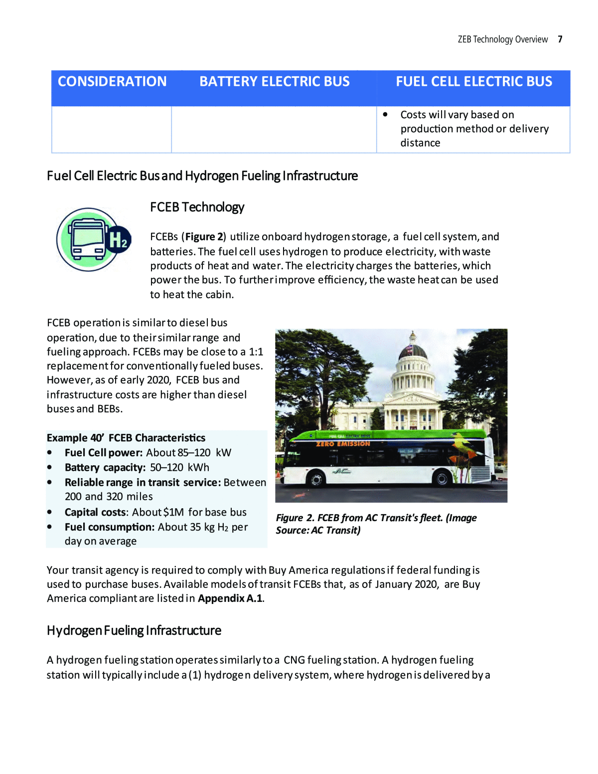
ZEB Technology Overview 7 CONSIDERATION BATTERY ELECTRIC BUS FUEL CELL ELECTRIC BUS ⢠Costs will vary based on production method or delivery distance Fuel Cell Electric Bus and Hydrogen Fueling Infrastructure FCEB Technology FCEBs (Figure 2) utilize onboard hydrogen storage, a fuel cell system, and batteries. The fuel cell uses hydrogen to produce electricity, with waste products of heat and water. The electricity charges the batteries, which power the bus. To further improve efficiency, the waste heat can be used to heat the cabin. FCEB operation is similar to diesel bus operation, due to their similar range and fueling approach. FCEBs may be close to a 1:1 replacement for conventionally fueled buses. However, as of early 2020, FCEB bus and infrastructure costs are higher than diesel buses and BEBs. Example 40â FCEB Characteristics ⢠Fuel Cell power: About 85â120 kW ⢠Battery capacity: 50â120 kWh ⢠Reliable range in transit service: Between 200 and 320 miles ⢠Capital costs: About $1M for base bus ⢠Fuel consumption: About 35 kg H2 per day on average Your transit agency is required to comply with Buy America regulations if federal funding is used to purchase buses. Available models of transit FCEBs that, as of January 2020, are Buy America compliant are listed in Appendix A.1. Hydrogen Fueling Infrastructure A hydrogen fueling station operates similarly to a CNG fueling station. A hydrogen fueling station will typically include a (1) hydrogen delivery system, where hydrogen is delivered by a Figure 2. FCEB from AC Transit's fleet. (Image Source: AC Transit)
8 Guidebook for Deploying Zero-Emission Transit Buses supplier or produced on-site, (2) hydrogen storage tank(s), (3) vaporizer (for liquid storage), (4) compressor, (5) chiller, and (6) dispensing system that delivers the fuel to the vehicle (Figure 3). Gaseous hydrogen storage will require an integrated design with both low-pressure and high- pressure storage. Liquid hydrogen storage is more common for transit applications, as it allows for higher storage capacity. FCEBs available in the U.S. all require hydrogen to be dispensed at 350 bar (H35). See Figure 4 for examples of the equipment needed for gaseous hydrogen delivery, liquid hydrogen delivery, and on-site hydrogen production. While Figure 4 uses electrolysis as the example for on-site hydrogen production, natural gas reformation can also be used to produce hydrogen. Note that the hydrogen fueling station for your buses will not be compatible with most hydrogen fueling stations for light-duty fuel cell vehicles, which require hydrogen to be dispensed at 700 bar (H70). Many retail hydrogen stations that dispense at 700 bar can also dispense at 350 bar. Figure 3. Generalized hydrogen fueling station schematic. Figure 4. Summary of hydrogen fueling station delivery options. (Image Source: California Fuel Cell Partnership)
ZEB Technology Overview 9 Phase 5 Fueling Infrastructure Deployment provides more information on the design and deployment of hydrogen fueling infrastructure. A summary of hydrogen fueling station considerations is shown in Figure 5. Type of Structure Fueling Medium Production Method ü Permanent (all piping and electrical equipment below ground) ü Semi-permanent (all piping and electrical equipment above ground) ü Temporary (rented or leased mobile trailer) ü Liquid ü Gaseous ü Liquid or gaseous delivery ü On-site generation through electrolysis or natural gas reformation Figure 5. Summary of hydrogen fueling station considerations. Upon completion, your hydrogen fueling station will look and operate much like a traditional CNG fueling station (Figure 6). In addition to the fueling pumps depicted, the hydrogen storage, compression, and production equipment, if utilized, would be located nearby (Figure 7). Figure 6. Hydrogen fueling station. (Image Source: SARTA)
10 Guidebook for Deploying Zero-Emission Transit Buses While the initial investment in a hydrogen fueling infrastructure may be significant, scaling up hydrogen fueling infrastructure may be less costly and less land-intensive than scaling up battery charging infrastructure. Some equipment expansion may be needed, but the total footprint of a hydrogen fueling station is similar to a diesel or CNG station. For smaller FCEB deployments and during a fleet transition period, your facility will need fueling stations for both conventionally fueled vehicles and FCEBs. But if your transit agency phases out non-ZEBs, hydrogen fueling stations could occupy the existing footprint dedicated to diesel or CNG fueling. More detailed information on the approaches to hydrogen fueling is provided in Table 2. Table 2. Hydrogen fueling infrastructure summary. APPROACH TYPICAL INSTALLATION ADVANTAGES DISADVANTAGES Purchase liquid hydrogen from a supplier ⢠Delivered to the transit agencyâs fueling facility via trucks ⢠Requires cryogenic storage ⢠Less equipment to maintain ⢠Lower energy costs ⢠Similar procedure to diesel delivery ⢠Lowest initial cost for small fleets or tests ⢠Maintenance fees may be required ⢠Hydrogen unit costs may be higher than on-site production ⢠Supply chain dependent on multiple third parties (manufacturers and distributors) Purchase gaseous hydrogen from a supplier ⢠Delivered to the transit agencyâs fueling facility via Figure 7. Hydrogen fueling station equipment. (Image Source: SARTA) trucks or a pipeline
ZEB Technology Overview 11 APPROACH TYPICAL INSTALLATION ADVANTAGES DISADVANTAGES ⢠Gaseous hydrogen must be stored in pressure vessels Produce hydrogen on- site through electrolysis ⢠Electricity is used to convert water into hydrogen and oxygen. The hydrogen is captured and stored. ⢠Opportunities to utilize renewable energy to produce hydrogen, reducing the carbon footprint of operations ⢠Transit agency controls and manages production ⢠Renewable fuel source ⢠Unit cost of hydrogen may be lower than delivery ⢠High electricity consumption ⢠Higher capital costs and maintenance requirements for additional equipment ⢠Service may be disrupted if hydrogen production system experiences a failure ⢠Significant ground storage needed Produce hydrogen on- site through natural gas reformation ⢠Steam and methane from natural gas react at high temperatures to produce carbon dioxide and hydrogen ⢠Transit agency controls and manages production ⢠Unit cost of hydrogen may be lower than delivery ⢠Fossil fuel source (natural gas-derived methane) ⢠High electricity consumption ⢠Higher capital costs and maintenance requirements for additional equipment disrupted if hydrogen production system experiences a failure ⢠Significant ground storage needed ⢠Service may be
12 Guidebook for Deploying Zero-Emission Transit Buses BEB and Charging Infrastructure Technology BEB Technology BEBs use onboard battery packs to power all bus systems. BEBs generally have no tailpipe emissions, however some transit agencies utilize an auxiliary fuel-fired heater to increase range in cold months. Generally, two types of BEBs are available: (1) long or extended range and (2) fast charge. Chargers can be plug-in, overhead conductive, or inductive. Any type of charger may be used at the depot or on-route. Your transit agency is required to comply with Buy America regulations if federal funding is used to purchase buses. Transit BEBs that, as of January 2020, that were Buy America compliant are listed in Appendix A.2. Long or Extended-Range BEBs Long- or extended-range BEBs have larger battery packs for maximum range between charges and may use batteries that favor lower power charges. These buses are typically charged one or two times per day. Fully recharging a battery can take up to 8 hours or more, depending on the size of the bus battery and the power output of the charger. Depending on your service needs, long-range BEBs may not be 1:1 replacements for conventionally fueled buses due to the range limitations and required downtime for charging. Example Long-Range 40â BEB Characteristics ⢠Battery capacity: 250â660 kWh ⢠Reliable range in transit service: < 150 miles on a single charge in most cases ⢠Capital costs: About $740K for base bus ⢠Charging approach: 50â125+ kW chargers, typically charged overnight or midday Fast-Charge BEBs Fast-charge BEBs have smaller battery packs that are capable of frequent high-powered charges. Fast-charge BEBs typically charge on-route several times per day. If the on-route charging capabilities are implemented effectively, the buses will recharge every time they return to the charger and can run indefinitely without needing to stop for an extended charging session. If the system is deployed correctly, on-route charged buses receive sufficient charge each time at the charger to permit a bus to periodically miss a charge throughout the day, if needed for schedule adherence or charger maintenance. For this reason, fast-charge BEBs can often be a 1:1 replacement for conventionally fueled buses.
ZEB Technology Overview 13 Example Fast-Charge 40â BEB Characteristics ⢠Battery capacity: 50â250 kWh ⢠Reliable range in transit service: Indefinite range with periodic charging of sufficient duration ⢠Capital costs: About $750Kâ$1M for base bus ⢠Charging approach: 150â450+ kW overhead or wireless chargers, typically charged on-route BEB Charging Infrastructure Three options exist for BEB charging technology: plug-in charging, overhead conductive charging, and wireless inductive charging. Any of these types of chargers can be used to charge BEBs either at the depot or on-route. Typically, plug-in chargers are primarily used to charge buses at the depot, and overhead conductive or wireless inductive chargers are used to charge buses on-route. However, the appropriate charging technology and approach will depend on fleet size, charger power, route characteristics, and available space. Overhead or inductive charging may be necessary for large-scale BEB fleets with limited space at the depot for chargers, while high-power plug-in chargers may be suitable for on-route range extension. A BEB charging station will typically include (1) a transformer, (2) switchgear, (3) a charger, and (4) a dispenser (Figure 8). Additional equipment may be required due to the size of the deployment, requirements from your electric utility, and the charging method. For example, a single transformer and switchgear may support multiple chargers, and one charger may have more than one dispenser. Your electric utility is typically responsible for the grid and transformer assets, while your transit agency is typically responsible for the switchgear and other remaining charger assets [Edison Electric Institute (EEI), 2019]. When selecting charging infrastructure, transit agencies must consider their route demands (e.g., speed, grade, stops,), bus service or blocking demands (e.g., deadheads, duration, and frequency), seasonal temperatures, passenger loads, available garage space and power, layover Figure 8. Generalized battery charging station schematic.
14 Guidebook for Deploying Zero-Emission Transit Buses or transit center locations and space, and utility rate schedules and costs. Transit agencies may choose a combination of chargers and charging approaches, utilizing both depot and on-route charging, to fully meet their needs. Integrating charging infrastructure into transit operations requires careful planning. BEB fueling infrastructure requires space and power. At scale, power demands will be significant. A thorough analysis of current and future ZEB plans should be conducted to install solutions that are scalable and make the most out of your facilities. Balance your infrastructure decisions with the understanding that the market is rapidly maturing, and future solutions may better accommodate your needs (See Phase 10: Emerging Opportunities). Electric utilities are also becoming more interested in alternative solutions for charging infrastructure. Speak to your utility provider to understand what incentives or pilot programs they might offer to support the purchase, design, or installation of fueling infrastructure. A summary of BEB charging infrastructure is shown in Table 3. Table 3. Battery electric bus charging infrastructure summary. INFRASTRUCTURE TYPE TYPICAL INSTALLATION ADVANTAGES DISADVANTAGES Plug-in charging ⢠Used to charge buses for a few hours (usually overnight or between blocks) ⢠One or two buses per charger with one or multiple dispensers ⢠Charge power: 50 to 125+ kW ⢠Compliant with SAE J1772 or J3068 standard ⢠Lower unit cost ⢠Additional chargers can be added for redundancy ⢠Total infrastructure cost may be more expensive for a larger fleet than other charging solutions ⢠Slower charging ⢠Identifying available space for equipment with large-scale deployments ⢠Require staff to plug and unplug the buses Overhead conductive charging ⢠One charger serves multiple buses ⢠Total infrastructure costs may be less expensive if fewer ⢠Pantographs may require additional maintenance
ZEB Technology Overview 15 As noted above, plug-in, overhead, and inductive chargers can be used either for depot charging or on-route charging. A summary of depot and on-route charging approaches is described in Table 4. ⢠Charging for 5 to 20+ minutes at higher power ⢠Charge power: 175 to 600 kW (as of 2020) ⢠Compliant with SAE J3105 standard chargers are needed for a larger fleet ⢠No manual connections ⢠Higher capital costs and construction costs per charger ⢠High-power charging may result in higher peak demand ⢠Not all OEMs offer overhead conductive charging Wireless inductive charging ⢠One charger serves multiple buses ⢠Charge power: 50 to 250 kW ⢠No manual connections or moving parts ⢠Could be used by multiple vehicle types ⢠No right-of- way restrictions ⢠Total infrastructure costs may be less expensive if fewer systems are needed for a larger fleet ⢠Aesthetically more pleasing ⢠Higher capital and construction costs per charger ⢠Charging efficiency varies based on bus alignment ⢠No interoperability among different wireless charger providers ⢠Not all OEMs offer inductive charging
16 Guidebook for Deploying Zero-Emission Transit Buses Table 4. Depot charging and on-route charging overview. CHARGING TYPE TYPICAL INSTALLATION ADVANTAGES DISADVANTAGES Depot Charging ⢠At the depot, maintenance facility, or garage ⢠Consolidation of charger and bus maintenance needs at one location ⢠Buses not restricted to specific routes ⢠Buses must be taken out of service to charge ⢠Fleetwide charge management and optimization is required to ensure buses are ready for pullout and to minimize electricity costs ⢠Consolidated charging at one location may result in higher peak demand On-route Charging ⢠Typically installed on- route or at transit centers where layovers may occur ⢠Charging for 5 to 20 minutes at higher power ⢠One charger serves multiple buses ⢠Can allow for indefinite bus operation ⢠Buses are able to remain in service while charging on route ⢠May increase resilience during power outages if chargers are on a different utility feed or service area ⢠Less redundancy due to fewer chargers, which could result in service outages ⢠Property rights may be required, limiting possible charger locations on-route ⢠May interfere with road clearances, or require a dedicated pull-off ⢠Less flexibility in route assignments or to use buses for special service and emergency purposes since buses must stay near a charger
ZEB Technology Overview 17 Plug-in Chargers Ground-mounted plug-in chargers (Figure 9) are a common choice for BEB charging, especially for overnight or midday depot charging. Most transit agencies utilizing depot charging have one charger per bus, or one higher-powered charger (i.e., 120+ kW) shared between two buses. Most higher-powered chargers have multiple dispensers that can charge several buses sequentially, limiting peak demand. Transit agencies should consider installing extra plug-in charger(s) to provide redundancy if there is a maintenance issue. Plug-in chargers can have air- cooled or liquid-cooled cables, with air-cooled being more common. Air-cooled cables have a current limit of 200 amps, therefore the total power delivered is dependent on the bus voltage. One potentially significant challenge for plug-in chargers is finding adequate space for a large number of chargers. Your transit agency may be able to accommodate a small number of plug- in chargers with your currently available space, but finding space to install plug-in chargers for a full fleet of BEBs may be more challenging. Often, bus yards or transit centers already maximize the space available for bus parking, and purchasing additional land may not be feasible or possible. Most transit agencies will need to redesign bus yards to accommodate the additional space necessary for the charging infrastructure. Space-saving solutions include having âfast charging lanesâ with higher-powered chargers, installing the dispenser remotely from the rest of the electronic equipment, or utilizing overhead gantries or other cord management solutions where charging cords can be pulled down from the ceiling. There are limits to the length of charging cables, but these options may provide alternate solutions to installing all of the charging equipment directly next to where the bus will be parked. Electrical infrastructure needs for a large fleet of BEBs may also be a significant challenge for transit agencies. 100 buses charging simultaneously at 100 kW each requires at least 10 MW of power. This will likely require significant power distribution upgrades. Ensure that you discuss your short- and long-term infrastructure planning needs with your electric utility so they can help you plan for needed upgrades.
18 Guidebook for Deploying Zero-Emission Transit Buses Overhead Conductive Charging Overhead chargers are used for fast- charge scenarios. Overhead charging equipment typically uses a pantograph, where the moving parts are on the bus (Figure 10), or inverted pantograph, where the moving parts are on the mast (Figure 11). Not all bus OEMs offer both options. For high-powered overhead or inductive charging solutions, an enclosure with the transformer, switchgear, and charging equipment would be located nearby as well (Figure 12). A benefit of using bus-mounted pantographs is that a malfunction with the moving arm that attaches to the charger on one bus does not take the entire charging station out of service. Maintenance and inspection of the onboard charging equipment is easier if the buses return to the garage daily. Figure 10. Overhead charger with pantograph (moving parts on bus). (Image Source: Mike Deal, Winnipeg Free Press) Figure 9. Plug-in charging examples. (Left Image Source: Rodrigo Garrido/Reuters; right Image Source: UITP)
ZEB Technology Overview 19 A risk of the inverted pantograph approach is that a malfunction of the charging station may have a significant impact on service, if the BEBs are unable to use the charger. Redundant equipment, or backup depot charging capabilities, can mitigate service risks. However, the primary benefit of the inverted pantograph approach is that you do not have to purchase and maintain a pantograph for every bus, which can be a significant cost and add weight to the bus. With either approach, operators must be trained on proper alignment for overhead charging, as improper alignment could cause a bus to miss a charge or have less available time to charge if the operator has to circle back around to the charger, if used on-route. Ensure that your on- route charging scenario is flexible enough to allow a bus to miss at least one charge throughout the day without impacting service. Inductive Charging Inductive chargers may also be used for high-powered charging, although maximum power levels for inductive charging have lagged behind high-powered conductive charging. Inductive chargers are built into the roadway, which eliminates any concerns about overhead clearances, does not obstruct sidewalks or roads, and may be more aesthetically pleasing. There are no moving parts with an inductive charger, which may lower maintenance requirements (Figure 13). However, there may be significant costs to remove and repair the charger if there is an issue. Proper alignment is critical for achieving maximum charging power, therefore drivers typically use visual cues for alignment. Figure 14 shows an example of how painted guides at the charging station can support proper alignment. Ensure that your on-route charging scenario is Figure 12. Overhead charging electrical equipment. (Image Source: Star Metro) Figure 11. Overhead charger with an inverted pantograph (moving parts on charger). (Image Source: TriMet)
20 Guidebook for Deploying Zero-Emission Transit Buses flexible enough to allow a bus to miss at least one charge throughout the day due to improper alignment without impacting service. Figure 14. Example guide on the door to instruct a driver if they are properly aligned for on-route charging. (Image Source: CTE) Figure 13. Example of inductive charging capabilities. (Image Source: CARTA)
