
2
Materials Selection in Structural Design
This chapter discusses the structural design context for materials selection, the materials selection process, the evolution of computer systems that support the design process, and the needs for materials information. The committee chose to describe the structural design process using aerospace vehicle design as a case study. This chapter is based, in part, on information gathered by the committee during a two-day site visit to the Boeing Commercial Airplane Group1 and comparative data on the Grumman design process. However, the design process and information needs detailed here are generic and applicable to structural designs in many industries (e.g., buildings, bridges, oil rigs, automobiles, ships, and spacecraft).
CONCURRENT ENGINEERING AND DESIGN ORGANIZATION
The design and development of a structure like an aircraft is enormously complex. The original sequential approach to aircraft design was to break the structure and systems into manageable sections. Preliminary designs of each section were then evaluated sequentially and modified by a multitude of different engineering, manufacturing, quality-assurance, and operations-support experts (Figure 2-1). This sequential approach led to extensive changes and errors during and following the design process, problems with communications between the different disciplines, increases in development costs, and extensions in design and manufacturing schedules. Consequently, the amount of needed rework and redesign accounted for a significant proportion of production costs.
The concurrent engineering approach, supported by centralized digital databases for geometry, materials, fabrication, and assembly processes and paperless drawings, was proposed to improve the design process and reduce rework and redesign (Winner et al., 1988). Figure 2-2 compares the sequential and concurrent engineering approaches.
Boeing has implemented concurrent engineering through an approach that uses design build teams (DBTs). The DBT approach establishes an IPDT for designing new products and systems and executing a concurrent engineering/manufacturing process. The team goals are to produce error-free designs that are optimized in terms of performance, weight, and production and operating costs.
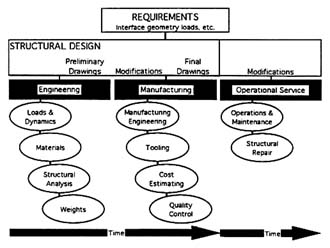
Figure 2-1 The sequential engineering approach to structural design. Reprinted courtesy of RNH Associates, Incorporated.
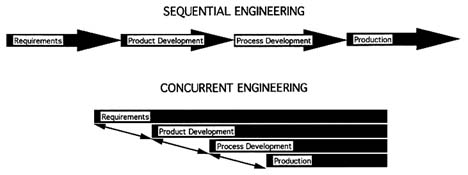
Figure 2-2 A typical comparison of sequential and concurrent engineering. Variations of this illustration are presented in Winner et al. (1988), Whitney et al. (1988), and NRC (1991).
The first step in the DBT approach is to divide the systems into major categories (e.g., structure, avionics, flight controls, mechanical systems, environmental systems, hydraulics, flight deck, and payload) as well as generic integration areas (e.g., airworthiness, reliability, and maintainability). These categories are then further subdivided. For instance, the basis structure divisions are body, wing, empennage, and propulsion system. These, in turn, are subdivided even further into manageable components and subcomponents, each of which is the responsibility of a separate DBT. For example, the main body components are cockpit, forward section, center section, rear section, and tail fuselage, as well as doors, door cutouts, floors, and floor beams. A typical hierarchical relationship between the IPDT and the DBTs is shown in Figure 2-3.
Boeing initially implemented the DBT system in an attempt to remain competitive in the global marketplace (NRC, 1993). The Boeing 777 program peaked at a total of approximately 250 DBTs, including 97 DBTs related to structures.
The structural DBTs (Figure 2-4) are composed of design, structures, materials, manufacturing (e.g., tooling and machining), quality control, and cost analysis experts; some teams also include liaison representatives from key subcontractors. Additional support may also be provided as required by representatives from other company divisions or by specialists on a part-time basis. The team members from the various disciplines responsible for creating a specific component or subsystem from conception through final design are collocated, and each team member is expected to participate fully in the DBT decision making process (Boeing Commercial Airplane Group, 1991). After the total design (including tool design) is completed, manufacturing is empowered to review and approve engineering data sheets verifying producibility prior to drawing release. A simplistic representation of the interactions within a typical DBT is shown in Figure 2-5. An important aspect of the process indicated in the figure is that optimization decisions are made from the perspective of the entire system, not from that of a particular subsystem.
Although concurrent engineering has considerably reduced rework, structural design and material selection remain iterative, cyclical processes. Structural analyses are performed on candidate preliminary design, and modifications are made to satisfy structural requirements. Weight and cost estimates are used for tradeoff studies to
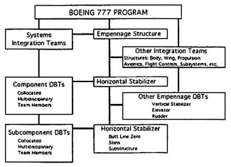
Figure 2-3 An example of a typical structures DBT hierarchy: Boeing 777 Horizontal Stabilizer DBTs. Source: Boeing Commercial Airplane Group.
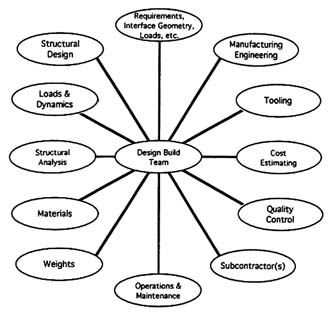
Figure 2-4 The expertise in a structural design concurrent engineering team. Reprinted courtesy of RNH Associates, Incorporated.
Each DBT records team notes, memoranda, and summaries of project reviews in DBT libraries. These can be accessed by other DBTs to obtain information and digital design data. This allows rapid dissemination of changes that affect the interface between components, facilitates tradeoffs using global criteria, and ensures storage of lessons-learned data for future designs. These records are primarily found in hard-copy form. Although some are filed electronically, they are not available for on-line reference.
MATERIALS SELECTION DURING COMPUTER-AIDED DESIGN
A DBT team requires an enormous amount of detailed information to develop structures that will satisfy performance, reliability, safety, weight, and durability requirements at economical production, operation, and maintenance costs. In the 1960s, structural design and analysis consisted of slide-rule and adding-machine calculations using formulae and tables from handbooks in combination with numerous assumptions based on prior experience. The resulting designs were then evaluated by materials, manufacturing, and cost-estimating personnel who fed back their recommendations for design changes. Design and engineering operations are currently performed rapidly and accurately by DBT members using interactive computer-aided engineering or computer-aided design and computer-aided manufacturing (CAD/CAM) programs. Many different integrated computer-aided engineering and CAD/CAM systems are currently available. Even the most advanced of these focus only on finite element analysis (FEA) or boundary element analysis computer programs and currently have little materials selection expert system capabilities.
Computer-aided engineering and CAD/CAM systems generally use a mixture of bars, panels, and solids, which are utilized from preliminary design through drawing release. The structure is predominantly modeled using combinations of bars and panels for the structural analysis and optimization programs because of the significantly longer computer times needed to model the structure and complete the analysis or optimization using solids. Solid elements are only used when the structure cannot be
Figure 2-5 The interactions of a typical DBT during initial concept development. Source: Boeing Commercial Airplane Group.
realistically modeled using the simpler elements or when more accurate determination of the three-dimensional state of stress or strain in the component is needed. For example, Grumman used the model of a wing for the X-29 and associated FEA (Figure 2-6) in combination with a fuselage model to determine the loads in the structure and the dynamic and aeroelastic behavior of the wing required to preclude divergence and flutter. Aerodynamically induced structural divergence was avoided by designing the carbon-epoxy covers to provide bending-twisting coupling to the wing, taking full advantage of the anisotropic properties of the composite material. This model was iteratively appraised by structural analysis, weight optimization, and divergence analysis computer programs to determine the geometry and orientation of the carbon-epoxy tape for each of the 148 plies in the upper wing skin and the 158 plies in the lower wing skin. The same model and computer programs were then used for selection of the materials and the sizing of the cap areas and web thicknesses for the other wing components. As shown in Figure 2-6, the wing covers are carbon-epoxy. The other materials used in the wing component are steel, 6A1-4V titanium, 2024 aluminum, an woven glass-epoxy (Hadcock, 1985).
Three-dimensional models of forgings or machined parts are used for more detailed analysis and sizing of components, such as complex wing-to-fuselage attachment fittings and control surface hinges. These models predict the boundary loads and constraints from the overall FEA. The information from these programs can be electronically transferred to CAD/CAM systems to generate the drawings of the detail parts and assemblies for manufacturing engineering.
In all these programs, material properties and external geometry are generally input data. Structural optimization is done iteratively. Structural geometry, which depends on material properties, panel thicknesses, and stiffener sizes,
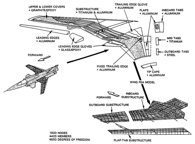
Figure 2-6 A model of the wing of the Grumman X-29 and associated FEA. Source: Northrop Grumman.
can be automatically adjusted during the iterations. The effects of changes in materials selection can be evaluated by executing the programs with different materials-properties data sets. This design tradeoff analysis process can be very time consuming, particularly when there are large numbers of candidate materials for each part and a range of structural analysis tests, such as thermal strains; dynamic behavior; fatigue; fracture; durability; and, in the case of combat aircraft, survivability. However, optimization programs are emerging that will allow the selection of best choices given the constraint parameters specified by the design engineer.
The aerospace industry has traditionally adopted a rigorous, yet conservative, materials selection process to minimize the risk associated with the introduction of new, and therefore less-proven materials. Risk as a factor in materials selection will be discussed in Chapter 3.
Some integrated computer programs are available for design, structural analysis, and production of complex-shaped castings and injection-molded plastic parts. These programs include thermal and flow analysis of the liquid material, design of patterns and molds that may include cooling passages to eliminate distortion and cracking during cooling, and determination of residual strains (see Appendix B).
SUMMARY OF MATERIALS INFORMATION REQUIREMENTS IN DESIGN
Table 2-1 provides a partial listing of materials-related information that is needed in the materials selection process. Materials selection is strongly influenced by overall product design, manufacturing, and cost requirements. Some of the product design requirements for aircraft structural design are presented in Table 2-2.
The major structures and materials design interactions are shown diagrammatically in Figure 2-7. Material selection is directly or indirectly defined by the combination of these design interactions. These interactions include most of the information needs of a team to design and select the materials for a primary structure component.
A summary of designer wants pertinent to the application of expert systems in the materials selection process during structural design is listed in Table 2-3. This table provides the basis for establishing the range of information technologies pertinent to the materials selection process that will be assessed in the next two chapters.
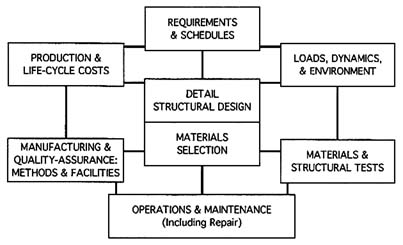
Figure 2.7 Structures and materials interactions. Reprinted courtesy of RNH Associates, Incorporated.
Table 2-1 Examples of Materials Information Required During Product Design
|
Material identification |
|
Material class (metal, plastic, ceramic composite) |
|
Material subclass |
|
Material industry designation |
|
Material product form |
|
Material condition designation (temper, heat treatment, etc.) |
|
Material specification |
|
Material alternative names |
|
Material component designations (composite/assembly) |
|
Material production history |
|
Manufacturability strengths and limitations |
|
Material composition(s) |
|
Material condition (fabrication) |
|
Material assembly technology |
|
Constitutive equations relating to properties |
|
Material properties & test procedures |
|
Density |
|
Specific heat |
|
Coefficient of thermal expansion |
|
Thermal conductivity |
|
Tensile strength |
|
Yield strength |
|
Elongation |
|
Reduction of area |
|
Moduli of elasticity |
|
Stress strain curve or equation |
|
Hardness |
|
Fatigue strength (define test methods, load, and environment) |
|
Temperature (cryogenic-elevated) |
|
Tensile strength, yield strength |
|
Creep rates, rupture life at elevated temperatures |
|
Relaxation at elevated temperatures |
|
Toughness |
|
Damage tolerance (if applicable) |
|
Fracture toughness (define test) |
|
Fatigue crack growth rates (define environment, and load) |
|
Temperature effects |
|
Environmental stability |
|
Compatibility data |
|
General corrosion resistance |
|
Stress corrosion cracking resistance |
|
Environmental stability |
|
Toxicity (at all stages of production and operation) |
|
Recyclability/disposal |
|
Material design properties |
|
Tension |
|
Compression |
|
Shear |
|
Bearing |
|
Controlled strain fatigue life |
|
Processability information |
|
Finishing characteristics |
|
Weldability/joining technologies |
|
Suitability for forging, extrusion, and rolling |
|
Formability (finished product) |
|
Castability |
|
Repairability |
|
Flammability |
|
Joining technology applicable |
|
Fusion |
|
Adhesive bonding |
|
Fasteners |
|
Welding parameters |
|
Finishing technology applicable |
|
Impregnation |
|
Painting |
|
Stability of color |
|
Application history/experience |
|
Successful uses |
|
Unsuccessful uses |
|
Applications to be avoided |
|
Failure analysis reports |
|
Maximum life service |
|
Availability |
|
Multisource? Vendors? |
|
Sizes |
|
Forms |
|
Cost/cost factors |
|
Raw material |
|
Finished product or require added processing |
|
Special finishing/protection |
|
Special tooling/tooling costs |
|
Quality control/assurance issues |
|
Inspectability |
|
Repair |
|
Repeatability |
Table 2-2 Typical Product Design Requirements for Aircraft Structure Development
|
Performance |
|
Design loads and conditions |
|
Associated air loads and accelerations |
|
Fuel usage |
|
Cabin and cargo hold loadings |
|
Temperatures and associated environmental data |
|
Fatigue spectra |
|
Fail-safe and safe-life design |
|
Aeroelasticity requirements |
|
Airworthiness standards and design requirements |
|
(Federal Aviation Administration: Federal Aviation Regulations, Advisory Circulars, etc.) |
|
Cost |
|
Design |
|
Production |
|
Preparations |
|
Material handling |
|
Safety |
|
Environmental and waste disposal |
|
Interfaces |
|
Geometrical tolerances |
|
Structural assembly |
|
Surface smoothness and tolerances |
|
Avionics |
|
Propulsion |
|
Environmental control |
|
Passenger accommodations |
|
Testing |
|
Load-temperature-environment spectra fatigue |
|
Quality |
|
Repair and reinspection |
|
Automated and nonautomated quality-control equipment |
|
Vendor/supplier qualification for new materials part fabrication |
Table 2-3 Summary of Designer Wants
|
Design Tools |
|
Material/processing/manufacturing tradeoffs in concept design |
|
Composite materials structures design tools |
|
Quality materials-selection aids |
|
Design Knowledge |
|
Information on the competition |
|
Lessons-learned knowledge base |
|
Materials-use case base indexed by multiple attributes |
|
Cost Knowledge |
|
Cost models |
|
Life-cycle costs |
|
Manufacturing costs |
|
Material prices |
|
Design Cycle Time/Time to Market |
|
More tradeoffs considered in given time Iteration for realistic materials targets |
|
Reduce cycle time to market |
|
Rapid deployment of new material |
|
Risk Reduction |
|
Trusted design and materials data |
|
Reduced risk in selecting new materials/processes |
|
Production Capabilities |
|
Facility availability |
|
Equipment availability |
|
Workforce experience capability and availability |
|
Viable supplier options |
|
Expert Agents |
|
Gather pertinent design information from multiple sources |
|
Specific expert systems for each component design team |


