
2
Subsonic and Transonic Facilities
INTRODUCTION
This chapter deals with the transonic and subsonic (low speed) wind tunnel facilities that are proposed to enable the United States to continue reaping the economic, environmental, and security benefits that preeminence in aviation provides. This evaluation is based on the National Facilities Study (NFS) report; interactions between the NFS team and the Aeronautics and Space Engineering Board (ASEB) during 1993 and 1994; and many individual and group discussions, including a facilities workshop hosted by the ASEB during May 16 –18, 1994 (see Appendix B).
The NFS report provides a good account of much of the study's work and the resulting conclusions. This chapter provides additional information on the scope and depth of the study and on subsidiary issues, such as how to proceed with the acquisition of new and improved wind tunnel facilities.
The aeronautics portion of the NFS report concentrates on commercial air transports. However, the NFS process also considered the needs of other segments of the aeronautics industry, including defense. Deliberations during the ASEB's facilities workshop and recently generated Air Force documentation have highlighted the benefits that high Reynolds number facilities will provide to the development of military aircraft (Gideon, 1993; Leaf, 1994; Yates, 1994). Also, Department of Defense personnel participated in the NFS and have endorsed its conclusions.
From the beginning of manned flight, wind tunnel testing has been an integral and necessary part of aircraft development. Throughout most of the growth years of the air transport industry, U.S. manufacturers had access to government wind tunnel facilities that were the best in the world. As discussed in more detail later in this chapter, timely tunnel access during competitive aircraft development programs is crucial. Since the 1930s, the availability and ready accessibility of world-class facilities have been key factors enabling U.S. manufacturers to dominate the field.
The NFS report documents that Reynolds and Mach number performance of the best subsonic and transonic development wind tunnels in the United States and Europe are now close to parity.13 However, the average age of major U.S. tunnels is about 38 years, and many of the older U.S. wind tunnels are subject to costly maintenance and breakdown. Nonetheless, there are no adequate domestic alternatives for many older facilities. For example, during the past several years U.S. manufacturers have conducted a large amount of their low speed testing in European facilities during refurbishment of the Ames Research Center 12-foot subsonic wind tunnel.
In contrast, European industry has a new government-funded transonic facility coming on-line during 1994 that is expected to significantly outperform any transonic development facilities in the United States in terms of Reynolds number capability.
More-capable wind tunnels will facilitate improvements in aircraft performance and
|
13 |
NASA's National Transonic Facility can test at much higher Reynolds numbers than the new European Transonic Wind Tunnel (ETW). However, the National Transonic Facility is primarily a research facility, and it has very low productivity. Although productivity enhancements are planned, the ASEB agrees with the NFS that it is not practical to transform the National Transonic Facility into a development facility such as ETW, which was designed from the beginning to serve as a development facility. ETW has features such as cooled model set-up rooms and quick-change model carts that provide it with productivity several times higher than the National Transonic Facility, even with productivity enhancements. |
producibility. However, as documented by the NFS, no wind tunnel in the world meets or can be affordably modified to meet the goals that the NFS generated for development of future transport and military aircraft (see Table 2-1).14
Table 2-1 Proposed Capabilities of New Low Speed and Transonic Wind Tunnels
|
TUNNEL PARAMETER |
LOW SPEED TUNNEL |
TRANSONIC TUNNEL |
|
Reynolds Number |
20 million at Mach 0.3 (full span model) 35 million at Mach 0.3 (semi-span model) |
28.2 million at Mach 1 (full span model) |
|
Mach Number |
0.05-0.6 |
0.05-1.5 |
|
Productivity |
5 polars per occupancy hour* |
8 polars per occupancy hour |
|
Operating Cost |
<$1,000/polar |
<$2,000/polar |
|
Operating Pressure |
5 atmospheres |
5 atmospheres |
|
Total Temperature |
110°F |
110°F at Mach 1 |
|
Maximum Power |
45 MW |
300 MW |
|
Test Section Size |
20 ft × 24 ft |
11 ft × 15.5 ft |
|
Flow Quality |
Low turbulence |
Low turbulence |
|
Acoustic Test Capability |
Acoustic test chamber |
Not applicable |
|
*A polar is a single test run consisting of 25 data points (see Appendix D). |
||
Source: NFS, 1994.
The NFS report examines the ground test requirements of commercial air transports, which have very high flight Reynolds numbers (in excess of 60 million for the 747). An analogous situation exists for military aircraft—flight Reynolds numbers for current aircraft are as high as 60 million for the C-5 and considerably higher for the B-2.
IMPORTANCE OF GROUND-BASED FACILITIES
Ground test facilities are important, because they allow new aircraft designs to be tested early in the development cycle, thus minimizing the time and expense of making changes after the aircraft is committed to manufacturing and flight test. As aircraft have grown in size and capability, the ability to test at or near flight conditions with current tunnels has nearly disappeared for many classes of aircraft. Extrapolated data from existing wind tunnels often contain errors associated with their inability to test at these high Reynolds numbers. Such errors have caused program delays, increased costs, and limited the performance of aircraft such as the C-141, C-5, C-17, F-111, and B-2 (Table 2-2). These problems are likely to persist until aircraft designers have access to improved facilities to validate their design analyses. The cost risks associated with technical uncertainties and potential program delays affect the initiation of future aircraft development, especially for private companies.
The importance of the proposed low speed and transonic wind tunnels extends beyond their application to subsonic and transonic aircraft. They also will be important to supersonic aircraft such as high speed civil transports. These aircraft will operate in the low speed regime during take-off,
|
14 |
The NFS initially established a Reynolds number test capability of approximately 30 million as a goal for both the low speed and transonic wind tunnels. After assessing the impact of performance goals on facility design and cost, the NFS recommended accomplishing this goal in the low speed regime using semi-span models. |
acceleration, transonic flight over land, and landing. The design of the proposed new wind tunnels should be compatible with the test requirements of higher speed aircraft to the extent that this additional capability is affordable and does not unacceptably degrade the tunnels ' ability to execute their primary mission.
SCALING PARAMETERS
Key among the many physical effects that must be considered during the design and test of new aircraft are compressibility and viscous phenomena (see Appendix D). Mach number is a metric for compressibility, while Reynolds number indicates the ratio of the inertia forces to the viscous forces that the atmosphere exerts on a moving aircraft. To be absolutely certain that wind tunnel test results accurately model full-scale vehicles, ground tests should approximate the flight values of these parameters simultaneously. However, for some aircraft and flight conditions, this is prohibitively costly. To provide confidence in the test results, validated scaling techniques are required that cover the entire envelope of the test aircraft.
With nonpressurized wind tunnels, Reynolds and Mach numbers are varied simultaneously, and, for most conditions, separation of the effects of each variable on the accuracy of the test results is impossible. For unpressurized, subscale tunnels, extrapolation to flight conditions can produce unusable results. Even with a pressurized tunnel, which provides some capability to vary Reynolds and Mach numbers independently, data taken at low Reynolds numbers cannot always be extrapolated confidently to flight Reynolds numbers. For example, consider Figure 2-1 , which shows wind tunnel pitching-moment data for a Boeing commercial transport at three different flap settings as a function of Reynolds number and angle of attack.15 Reynolds number effects on pitching-moment characteristics are small up to the stall angle of attack. However, post-stall measurements of pitching moment are not repeatable at high flap settings for various Reynolds numbers. Thus, designers would not be able to use low Reynolds number tests such as these to fully and accurately determine flight performance. Development testing in new wind tunnels with the capability to simulate flight Reynolds numbers would overcome this problem.
Table 2-2 Prediction Errors Associated with Development Testing at Low Reynolds Number
|
AIRCRAFT PROGRAM |
AREAS OF PREDICTION ERROR |
|
|
C- 141 |
Transonic wing shock location Pitching moment Tail loads |
|
|
C-5 |
Drag rise with Mach number |
|
|
C- 17 |
Range/payload |
|
|
F-111 |
Transonic interference effects Airframe drag |
|
|
B-2 |
Pitching moment Aerodynamic drag with weapon bay door open Inlet distortion characteristics |
|
|
Source: J.M. Griffin, 1994. |
||
Satisfactory post-stall performance of commercial transports is required for certification by the Federal Aviation Administration, which mandates testing of aircraft beyond their normal flight envelope. For an aircraft designer who is limited to low Reynolds number facilities, variations in test data represent uncertainties that must be compensated for by either using a more conservative (and lower performance) design or accepting additional risk. Over the long run, either approach will reduce competitiveness relative to a more accurate design approach that uses high Reynolds number ground test facilities.
All of the mechanisms associated with high Reynolds number flow are not fully understood, nor is the variation of these mechanisms with Mach number. This suggests that some important flow
|
15 |
Boeing collected the data plotted in Figure 2-1 as part of a commercial product development program that used the Ames 12-foot Low Speed Pressure Tunnel. Reynolds number was varied by adjusting tunnel pressure. |
phenomena have not yet been identified. Understanding physical mechanisms is important, because it can lead to new, more-effective analytical and test approaches, creating design innovations that significantly advance aircraft performance. Geometry, Reynolds number, Mach number, lift system configuration, and lift all interact, so extrapolating test results to other combinations of these variables is questionable. Building better ground test facilities is a cost-effective way to avoid problems in the flight testing phase and ensure that new designs will perform as expected.
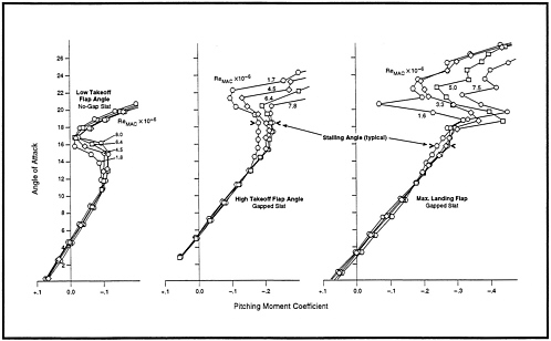
Figure 2-1 Effect of Reynolds Number on Wind Tunnel Measurements of Aircraft Pitching Moment during Take-off and Landing. Source: Boeing, 1994.
COMPUTATIONAL SIMULATION
Computational methods such as computational fluid dynamics are used during the aircraft design process to analyze and predict aerodynamic characteristics in all speed regimes. However, they must be validated by experimental ground and flight tests before they can be relied on for design or evaluation in any phase of development. Improved aerodynamic wind tunnel testing will provide better understanding of aircraft fluid dynamics, including Reynolds number and boundary layer effects. This understanding will permit more-accurate scaling of ground test data to inflight performance. Continued work to improve computational methods and continued flight exploration (e.g., X-planes) are required adjuncts to the acquisition of new and improved wind tunnels. Better scaling methodologies are needed as soon as possible. They will be useful during the interim before new tunnels are available, and, in the long run, they will extend the utility of new tunnels for the design of very large and unusually configured future aircraft.
TUNNEL PRESSURE AND MODEL DESIGN CONSIDERATIONS
Wind tunnel models are carefully designed to assure that their aerodynamic, structural, and dynamic characteristics meet the full-scale design intent. This requires that model surface roughness, protuberances, cut-outs, etc., faithfully represent the full-scale aircraft.
Designing new tunnels with higher operational pressures makes it possible to reduce the size of the facilities without sacrificing Reynolds number capability (see Appendix D). The realities of model design and fabrication, however, generate practical limits on the use of smaller models and elevated pressures. For a given Mach number, dynamic pressure and structural loading of the model increase in direct proportion to gas density and, hence, tunnel pressure. High pressures increase demands on the physical integrity of the model and the wind tunnel model support structure. This is especially significant for transonic tunnels, where full-scale dynamic pressures are already high.
For subsonic wind tunnels, model design constraints are related to the loading of high-lift system components such as flap mechanisms and tracks. Excessive dynamic pressures can cause these model components to fail or distort unless they are oversized to increase their strength. However, oversizing model parts, so that they are no longer properly scaled, causes data accuracy to become an issue. Current practice with subsonic wind tunnels has shown that design solutions are available for accurate scale models with affordable and easily workable materials up to test pressures of at least 5 atmospheres. The extent to which higher pressures could be used without unduly degrading the cost, efficiency, and effectiveness of the overall ground test process is unclear. As a result, the interaction between tunnel pressure and model design requires further investigation for both transonic and subsonic tunnels. Use of higher pressures is likely to be more feasible for subsonic wind tunnels than for transonic wind tunnels because of the differences in full-scale flight dynamic pressure.
WIND TUNNELS IN THE DEVELOPMENT PROCESS
Wind tunnel data are used to confirm or modify aircraft designs in an iterative manner until flight tests verify performance and handling characteristics. Uncertainty exists until flight tests are completed, but comprehensive ground tests at conditions that closely simulate flight conditions minimize this uncertainty. Thus, whenever possible, tunnel tests are conducted throughout the projected flight envelope of the aircraft. Many thousands of data points are recorded and analyzed for each configuration tested. A typical complete airplane development requires about 2.5 million aerodynamic simulations (Rubbert, 1994).
During the design process, computational methods produce preliminary designs that are tested in wind tunnels. Analysis of tunnel test data often results in design changes. To test the modified design, the model must be removed from the working section of the tunnel, reworked, and returned. The ability to complete the rework–retest cycle within a single shift or overnight is needed to reduce design cycle time and facilitate completion of planned testing within wind tunnel schedule constraints. To achieve fast turnaround times, the proposed new tunnels will include features such as automated controls, airlocks for quick entry, and multiple quick-change test carts with self-test systems to verify model set-up. The cost of these capabilities is significant, but it is small compared with the cost of extending the aircraft development program or encountering unexpected problems during flight test. Model turnaround time, data recording and retrieval, and other operations that impact tunnel productivity need to be quick.
Advanced aerodynamics is not the only source of improved aircraft performance. Half of the performance improvements in modern aircraft are the result of improved engines. However, superior engines will not eliminate the importance of providing improved aircraft aerodynamic
configurations. Commercial jet engines are sold openly in the world marketplace, so future engine improvements will provide equal benefits to both U.S. and foreign airframe manufacturers. Without the proposed new facilities, U.S. industry will have to either indefinitely rely on the aging cadre of increasingly obsolete U.S. facilities or continue to stretch its design and development process across the Atlantic Ocean, taking advantage of the test time that European facilities make available to foreign users.
Although the highest priority need in the area of low speed and transonic facilities is for new development facilities, related research is also very important to long-term competitiveness. For example, the ability to construct practical development test facilities that use heavy gas (such as SF6) and/or very high operating pressures (15 atmospheres or more) would (1) greatly reduce facility size and cost and (2) increase Reynolds number test capability. Continued funding of appropriate research is an essential precursor to the development of future generations of ground test facilities, and it is also likely to directly contribute to future upgrades of existing and planned facilities.
INFLUENCE OF FASTER DESIGN/TEST CYCLE
When aircraft designers prepare to introduce a new product, they must decide how far to push available technology before selecting the final design. If U.S. designers have a more efficient design-test-redesign process than their competition, they can achieve either (1) a given level of performance sooner or (2) a greater level of performance within a given period of time. Either situation, or a combination of the two, would allow U.S. products to capture a larger share of the international market than is otherwise possible, either by beating the competition to market or by introducing products with better performance.
On the other hand, if the United States is hampered by delays in its product design and development process, then economic returns will be greatly diminished even if the country ultimately produces products with capabilities equal to the competition. Inefficient design or test processes allow the competition to produce an equal or better product sooner, and there is a tremendous competitive disadvantage in arriving late to the marketplace. Many airlines standardize aircraft purchases over long periods of time to simplify maintenance and training. Thus, late introduction of a new aircraft model may permanently diminish its sales as individual airlines choose to stay with a competitors ' product rather than acquire a mixed fleet of aircraft.
The high cost of developing new aircraft imposes an additional penalty. Slow design and test methodologies extend the period of time that manufacturers must fund product development, increasing the cost of bringing new products to market and reducing competitiveness.
Increasing shift hours on low-productivity facilities is not a viable strategy for competing with high productivity facilities, because the test phase of competitive aircraft design programs typically consumes every available hour of facility run time. As noted by the NFS report, development of new transport or fighter aircraft requires about 20,000–25,000 hours of wind tunnel testing (using existing facilities). Every increase in facility productivity directly reduces the number of test hours required to develop new aircraft and shortens the time to market.
U.S. aircraft manufacturers currently operate in an extremely competitive environment. Even though U.S. designers have access to European facilities, the ASEB believes that the scheduling constraints faced by U.S. users of European facilities and the inefficiency of conducting transatlantic design and development efforts inevitably delay the introduction of new products. Conversely, European competitors have greater access to better test facilities and, potentially, to the data generated when U.S. aircraft manufacturers use European wind tunnels. In combination with other improvements that the U.S. aeronautics industry is making in its design and manufacturing process, the ASEB believes that the construction of advanced development wind tunnels will be an
important contribution to the productivity of that industry.
The NFS did not conduct a detailed assessment of the option of building new international facilities in which all partners would have equal access and assured protection of competition-sensitive data. However, even with such an approach, U.S. industry believes that tunnel location could still create competitive inequities. Also, it seems doubtful that the Europeans, who are preparing to open the new European Transonic Wind Tunnel (ETW), would be inclined to participate in an international venture to build another transonic development facility that would draw users away from ETW.
Because of national security concerns, foreign facilities are especially inappropriate for development of military aircraft. The U.S. defense industry is generally limited to U.S. facilities, even if more-capable facilities are available overseas. Thus, the ASEB believes it is unlikely that new or existing foreign or international facilities will be able to adequately respond to near-term requirements for subsonic and transonic development testing of commercial and military aircraft.
The ASEB concurs with the NFS report that:
-
acquisition of advanced high productivity wind tunnels in the United States, where U.S. designers can efficiently coordinate their wind tunnel, model-building, and computational activities will improve the effectiveness and efficiency of the aircraft design and development process; and
-
these improvements are important to the economic viability of the U.S. aeronautics profession and industry because of the vital role that design process efficiency plays in the worldwide aircraft manufacturing competition.
WIND TUNNEL DESIGN REQUIREMENTS
The proposed design of the new low speed wind tunnel enables testing of the high lift systems that define aircraft performance during take-off, climb-out, and landing. The transonic tunnel supports testing during aircraft cruise and maneuvering at velocities up to Mach 1.6. (Commercial jet transports today cruise at speeds no higher than about Mach 0.9. The capability of the transonic tunnel to support testing at higher velocities is based on military requirements. It will also be important in the development testing of high speed civil transport designs.)
Although the ASEB did not independently analyze the tunnel design parameters shown in Table 2-1, it judges that they are well developed, and their achievement is reasonably assured. Although near-flight Reynolds numbers will not be achieved for the largest of the transport aircraft designs contemplated for the next decade, the target Reynolds and Mach numbers for each of the tunnels appear to be an acceptable compromise among tunnel cost, productivity, and technical risk. For example, the Reynolds number capability of the proposed transonic wind tunnel (28 million) will be significantly less than the design Reynolds number of the new ETW (50 million). However, the proposed U.S. facility will have much higher productivity (8 polars per hour versus 1.5 for ETW). The ASEB agrees with the NFS that this is an appropriate trade, particularly because U.S. designers have the option of using the U.S. National Transonic Facility (productivity of 0.36 polars per hour at a Reynolds number of 119 million) to conduct limited verification testing at very high Reynolds numbers.
The productivity and cost goals of the proposed subsonic and transonic facilities appear to be attainable for most tunnel tests. Other tunnel requirements concerning turbulence, noise, wall boundary interference effects, simulation of jet-engine inlet and exhaust flows, and interactions of engine flows with external aerodynamic flows are acknowledged by the NFS, and the ASEB anticipates that tunnel design solutions will be further refined during the detailed design phase. The design phase also should ensure that features necessary to adequately accommodate development testing of military aircraft, including stores separation testing, are incorporated into the design of the new wind tunnels as appropriate. Ongoing efforts
by the U.S. Air Force to more closely define military requirements for future development wind tunnels will assist in this effort. For example, the Air Force Materiel Command hosted a government/industry workshop on August 2-3, 1994, at Arnold Engineering Development Center to assess military requirements for development wind tunnels. Workshop participants included representatives of the Wind Tunnel Program Office.
The ASEB agrees with the NFS that building the two tunnels as proposed is likely to enable subscale development testing for more than half of the new commercial transport aircraft projected for the next 20 years or so at flight Reynolds and Mach numbers. In particular, the new wind tunnels would allow testing models of existing aircraft such as the B-737 and MD-90 at flight Reynolds number. This is likely to significantly improve the correlation of wind tunnel and flight data for future designs of conventional aircraft that have flight Reynolds numbers beyond the test limit of the proposed tunnels. However, the flight Reynolds numbers of (1) very large commercial transports, (2) high speed civil transports, (3) high performance military aircraft, and (4) some revolutionary design concepts that might emerge in the future would exceed the capabilities of the proposed tunnels. Thus, the test results for these aircraft would have to be extrapolated to analyze their performance at flight Reynolds number. Nonetheless, this process would generally be more accurate than extrapolations based on data obtained from the less capable tunnels now available.
During the tunnel design phase, additional tunnel configurations should be considered to evaluate lower cost alternatives such as:
-
making relatively small increases in tunnel operating pressure (increasing pressure by 10 percent—to 5.5 atmospheres—could reduce facility cross-section size requirements and the cost of facility construction on the order of 20 percent); 16 and
-
building a single tunnel with both low speed and transonic test capabilities.
The extent to which performance and operational costs would be compromised by building a single, dual-use facility should be evaluated in terms of reduced acquisition costs. Joint utilization of control facilities or airflow and power components for both subsonic and transonic testing may also be feasible. However, like the option of building a single tunnel for subsonic and transonic testing, this would reduce total available test hours and the ability of new facilities to satisfy utilization rates projected by the NFS. These utilization rates, which appear to be reasonable, should be verified as part of the proposed assessment of using a single facility for both subsonic and transonic testing.
As previously stated, the ASEB agrees that the proposed Reynolds number capabilities for the low speed and transonic wind tunnels seem appropriate. However, given the long lifetime of major wind tunnels, it would be prudent to consider how future facility operators and users might wish to enhance the proposed new facilities. Experience with existing facilities shows that test requirements often evolve beyond the expectations of the original designers. Facility upgrades are unlikely to be cost-effective unless the baseline design anticipates the need for future modifications and makes allowances for them. Therefore, the ASEB recommends conducting design trade studies to evaluate possible future upgrades to the Reynolds number capabilities of the proposed tunnels. These assessments should take into account the differences in tunnel and model parameters (such as dynamic pressure) between the subsonic and transonic wind tunnels.
The design trade studies should specifically assess the relative merits of operating each of the proposed tunnels (1) at increased pressure (up to 8 atmospheres), (2) at reduced temperatures (down to about -20°F), and (3) with heavy gas. Testing with
|
16 |
For a given Reynolds number capability, increasing design pressure by 10 percent allows an equivalent reduction in the maximum characteristic length a wind tunnel must accommodate. This allows reduction of the cross-sectional area of the wind tunnel test section by about 20 percent. Thus, to the first order, a 10 percent increase in pressure could reduce a wind tunnel's overall size and cost by about 20 percent. |
heavy gases increases Reynolds number in much the same way as increased pressure, although the use of a test gas other than air raises questions about the validity of test data.17 Incorporating these capabilities into the new facilities would add significant cost. There are also technical concerns regarding wind tunnel tests using high pressure or gases such as SF6. However, it would add only a few percent to the cost of the new facilities to plan ahead for future upgrades that would use one of these capabilities. For example, initially designing the Low Speed Wind Tunnel pressure shell to withstand 8 atmospheres would facilitate subsequent facility upgrades from 5 atmospheres to higher operating pressures. Failure to initially build in growth capability would make future facility upgrades highly unlikely and limit the ability of these facilities to meet new ground test requirements.
Tunnel wear out and breakdown have been problems with some key existing facilities, primarily because of their age. The 12-foot subsonic wind tunnel at Ames Research Center is still a critical part of the U.S. facilities infrastructure even though it was built in 1946. Accordingly, attention should be given to the selection of simple and robust tunnel designs, including appropriate materials, for the proposed new facilities. Designing selected subsystems and components with margin for growth relative to pressure and operating power could improve component reliability, increase facility lifetime, and reduce the costs of future upgrades.
PRELIMINARY DESIGN AND COSTS
NASA and the Department of Defense formed the Facilities Study Office (FSO) to support the NFS Task Group on Aeronautical R&D Facilities. One of the FSO's major tasks was to assess the costs, schedule, and technical merit of alternative concepts for new subsonic and transonic wind tunnels under consideration by the NFS. The work of the FSO is documented in Volume II-A of the NFS report.
The FSO prepared bottom-up comparative cost estimates for wind tunnel conceptual designs using a five-tier work breakdown structure. First, the FSO generated an initial engineering estimate of the cost of fabricating each work breakdown structure element. It then estimated the cost risk and design cost of each element. Cost risk accounted for uncertainties associated with design requirements, item complexity, design maturity, and site conditions. The average value of cost risk assigned was 24 percent. The total cost of each element of the work breakdown structure was formed by adding the engineering estimate, cost risk, and design cost. The NFS summed these costs for every element of the work breakdown structure to calculate the estimated construction cost. The FSO then estimated the project's total cost by adding the cost of (1) contractor profit; (2) bonding; (3) inflation during the construction process; (4) supervision, inspection, and engineering services; (5) preliminary and final system design; (6) government project management; and (7) a contingency equal to 10 percent of the estimated construction cost. For the NFS' preferred design, these last seven factors accounted for 47 percent of the project's total estimated cost.
The conceptual designs and accompanying cost estimates that this process generated appear to be well done. The cost estimates are especially thorough considering the early stage of the project. Nevertheless, pending the completion of a preliminary engineering report and formal design study, the ASEB surmises that these estimates remain subject to the usual range of uncertainties. The engineering design, bidding, and construction process should focus on cost containment as well as technical goals. The current budget environment makes it essential to prevent cost growth, even if this requires sacrificing some initial capabilities and deferring them to future upgrades.
The NFS report estimates that it would cost $3.2 billion and take 10 years to construct the proposed new wind tunnels using standard federal procurement procedures. It also reports that “nonstandard
|
17 |
When the test gas is not air, the test data must be interpreted to account for the impact of differences in the specific heat constant. |
(i.e. commercial like) acquisition and concurrent design and construction practices” could reduce cost and schedule to $2.55 billion and eight years. Although the NFS report characterizes the $2.55 billion, eight-year cost and schedule estimates as conservative, the ASEB cautions against further reductions in planned cost and schedule estimates unless they are justified by specific changes in the design or acquisition approach. The ASEB believes that the biggest risk faced by major projects such as this relate to the unexpected. Thus, that portion of the cost estimate that is attributable to cost risk and contingency planning should be carefully conserved to deal with unexpected problems that may arise.
ECONOMIC AND ENVIRONMENTAL FACTORS
The ASEB agrees with the NFS that development of the proposed high Reynolds number subsonic and transonic wind tunnels can provide economic benefits through:
-
competitive advantages associated with significant improvements in aircraft maximum lift capability and cruise efficiency, which are sensitive to Reynolds number effects;
-
reduced aircraft operating cost and structural weight;
-
higher payload and range;
-
increased sales of commercial transports and improved market share; and
-
higher gross domestic product, a more positive trade balance, and increased domestic employment.
Table 2-3 illustrates the performance gains that might be obtained by projected improvements in new aircraft (Boeing, 1994). The new high Reynolds number wind tunnels would facilitate the achievement of these gains by better simulating flight conditions during take-off, landing, and cruise.18 The maximum take-off weight, engine static thrust at sea level, fuel burn per seat at 2,000 nautical miles, and direct operating cost for two classes of airplanes are shown. Comparisons of these parameters illustrate the marked potential advantage of aircraft developed with the proposed new tunnels. Particularly impressive is the projected reduction of 18.9 to 22.2 percent in fuel burn. This improvement would provide a direct reduction in the engine emissions, environmental impact, and operational costs of new commercial aircraft.
The NFS report uses data taken from the Boeing Commercial Group's 1993 Current Market Outlook to project a potential transport aircraft market of $815 billion for the period between 1992 and 2010. The report also uses industry sources to estimate the economic benefits of the proposed new facilities. It estimates that the proposed new facilities would improve airplane cruise and take-off and landing performance by at least 10 percent each. Performance improvements are essential for the U.S. aeronautics industry to maintain or increase market share. Based on the information available to it, the ASEB considers these projected increases in performance to be potentially attainable and believes that the proposed facilities could substantially facilitate such improvements.
These forecast advantages do not include the probable operating and development cost reductions that would accrue to future U.S. military aircraft programs. In addition to direct cost reductions, access to improved ground test facilities would make advanced military aircraft more competitive in the world market, thereby further reducing the defense burden carried by U.S. taxpayers. Foreign sales of U.S. military aircraft result in lower unit costs for U.S. government and foreign purchasers.
Starting development of the proposed new tunnels as soon as possible will
|
18 |
The benefits shown in Table 2-3 include contributions from both proposed tunnels. The low speed wind tunnel would contribute to improvements in the design of high lift systems for take-off and landing. A new transonic wind tunnel would impact aircraft cruise performance. The National Facilities Study report concluded that cruise performance has greater leverage on aircraft operating costs than take-off and landing performance. The ASEB agrees with this assessment. |
maximize their economic payoff. There is an immediate need for the competitive advantages they offer, and their payoff will accrue far into the future.
Table 2-3 Illustration of Potential Improvements in Aircraft Performance.
|
AIRCRAFT TYPE |
||||
|
PARAMETER |
BASE QUAD |
IMPROVED QUAD |
BASE TWIN |
IMPROVED TWIN |
|
Maximum Take-off Weight (lb) |
1,240,000 |
1,113,000 |
534,800 |
480,600 |
|
Sea Level Static Thrust (lb) |
73,500 |
56,300 |
73,500 |
53,200 |
|
Fuel Burn/Seat at 2,000 nm (lb) |
162.1 |
131.5 (-18.9%) |
168.2 |
130.9 (-22.2%) |
|
Direct Operating Cost (¢/seat-mile) |
1.372 |
1.189 (-13.3%) |
1.391 |
1.196 (-14.0%) |
|
Assumptions: Quad airplane represents a potential new, very large commercial transport. Twin airplane represents a 777-equivalent design. Increases in M=0.03; Cruise L/D=4%; Takeoff L/D=6%; CLmax=15% |
||||
|
Source: Boeing, 1994 |
||||
Over the last 25 years, as European aeronautics technology has risen to equal U.S. technology, the U.S. market share in transport aircraft has declined by 30 percent. Although market share is a function of many different factors, if other nations achieve a higher level of aeronautical technology, erosion of the U.S. market share may accelerate, with accompanying reductions in balance of trade and jobs. Continued advances in aerodynamic technology are necessary to avoid this situation. The proposed facilities represent an investment that is only a small fraction of the potential future gain and will provide an opportunity to enhance U.S. technology development.
Although the precise size of the future transport aircraft market is uncertain, it is sure to be quite large. Projected annual sales for 2010 are $60 billion (in 1993 dollars), and between 25 and 35 percent of the total projected market is accounted for just by replacement of existing aircraft (McDonnell Douglas, 1992; Boeing, 1993). Consequently, investing in the resources necessary to maintain U.S. competitiveness is in the best interest of the country. However, the decision to build the high Reynolds number subsonic and transonic tunnels must balance the need for more-capable facilities with specific performance parameters, the costs of building and operating new facilities, and the economic benefits that are likely to result. Based on the analyses conducted by the NFS, other factors discussed in this chapter, and the benefits that the United States could derive from the tunnels in terms of balance of trade, employment, and economic activity, the ASEB recommends proceeding with the design and development of new subsonic and transonic facilities while more fully exploring the items recommended herein for further study.
Finding 2-1. With regard to low speed and transonic facilities, the findings of the Aeronautics and Space Engineering Board are as follows:
-
Significant aerodynamic performance improvements are achievable, and the nation that excels in the development of these improvements has the opportunity to lead in the global market for commercial and military aircraft.
-
New high-Reynolds-number ground test facilities are needed for development testing in both the low speed and transonic regimes to assure the competitiveness of future commercial and military aircraft produced in the United States. These facilities will also contribute to the development testing of supersonic aircraft, such as high speed civil transports, by characterizing flight characteristics during takeoff, acceleration, transonic flight over land, and landing.
-
Facility configuration trade-off studies conducted by the NFS on Reynolds number, productivity, and life cycle cost appear to be sound. Additional configuration studies are needed for both the subsonic and transonic tunnels. Each assessment should take into account the differences in tunnel and model parameters between subsonic and transonic wind tunnel testing. These additional assessments should cover the following topics:
-
using a single tunnel to test both the low speed and transonic speed regimes;
-
making incremental changes to tunnel operating pressures (e.g., from 5 to 5.5 atmospheres) to allow reduction of facility size and cost without sacrificing Reynolds number capability;
-
including within the baseline design the ability to provide future growth in Reynolds number capability through use of higher operating pressures (up to 8 atmospheres), reduced temperatures (down to about -20°F), and/or a heavy test gas (such as SF6); and
-
improving the robustness of the tunnel designs by designing facility components with margin for growth in pressure and operating power to improve component reliability, increase facility lifetime, and facilitate future upgrades.
-
-
Completion of planned upgrades to existing facilities is an essential complement to the acquisition of new facilities.
-
Facility research on high pressure wind tunnels and other wind tunnel concepts should continue. These efforts should include research related to high pressure wind tunnel models.
-
Scaling methods are essential to current design processes. Even with new facilities, scaling of ground test results will still be necessary to accommodate full-scale simulation of very large or innovative aircraft designs that may be developed in the future. Coordinated efforts to develop improved scaling methods that use wind tunnel testing, computational methods, and flight tests should be expanded.
-
New facilities offer potential benefits to the U.S. economy and the global environment that are large compared with the investments required.
Recommendation 2-1. The ASEB recommends the following:
-
NASA's Wind Tunnel Program Office should proceed with the design and development of new subsonic and transonic facilities while conducting the four design trade studies noted in Finding 2-1.c during the design phase of the wind tunnel program. It should also ensure that the detailed designs of the proposed new wind tunnels will adequately support requirements related to factors such as noise, turbulence, simulation of jet-engine flows, low speed testing of supersonic aircraft, and testing of military aircraft and systems.
-
NASA should complete planned upgrades to existing facilities as soon as possible.
-
NASA and the Department of Defense should continue facility research on high pressure wind tunnels and other concepts.
-
NASA and the Department of Defense should expand efforts to develop advanced scaling methods that involve wind tunnel testing, computational methods, and flight tests.
REFERENCES
Boeing . 1993 . Current Market Outlook, World Market Demand and Airplane Supply Requirements . Boeing
Commercial Airplane Group . March 1993 . Seattle, Washington : Boeing .
Boeing . 1994 . Cycled Airplanes and Their Performance . The Boeing Company . Briefing presented by Dr. Ken Hoefs to the Aeronautics and Space Engineering Board National Aeronautical Test Facilities Workshop, at the National Research Council Washington, D.C., May 16-18, 1994 .
Gideon, F.C., Jr. 1993 . Draft Mission Need Statement AFMC 004-93 . Aircraft/Propulsion/ Avionics Test and Evaluation Infrastructure Capability . Air Force Materiel Command . July 19, 1993 .
Griffen, J.M. 1994 . Memorandum to Arnold Engineering Development Center from Headquarters, Aeronautical Systems Center, U.S. Air Force . Aircraft Development Program Delays and Costs Due to Wind Tunnel Data Errors Associated with Reynolds Number Effects . April 25, 1994 . Wright-Patterson Air Force Base, Ohio .
Leaf, H. 1994 . Future Military Requirements Relative to Aeronautical Test Facilities . Briefing by Lt Gen Howard Leaf, Headquarters, U.S. Air Force Test and Evaluation, to the Aeronautics and Space Engineering Board National Aeronautical Test Facilities Workshop , National Research Council , Washington, D.C. , May 16–18, 1994 .
McDonnell Douglas. 1992 . 1992–2011 Outlook for Commercial Aircraft . Douglas Aircraft Company . Long Beach, California : Communications Group, Douglas Aircraft Company.
Rubbert, P.E. 1994 . What the Future Will Be—Subsonic Jet Transports . Presentation by Dr. Paul Rubbert to the Aeronautics and Space Engineering Board National Aeronautical Test Facilities Workshop , National Research Council , Washington, D.C. , May 16–18, 1994 .
Yates, R.W. 1994 . Memorandum for Headquarters, U.S. Air Force Test and Evaluation from Headquarters, Air Force Materiel Command . Defining Department of Defense Requirements for the National Facilities Study . March 1, 1994 . Wright-Patterson Air Force Base, Ohio .


