
4
Propulsion Facilities
INTRODUCTION
Turbopropulsion test facilities within the United States have the capability to test current air breathing engines under the operating conditions experienced during take-off, climb, cruise at flight speeds up to Mach 3.8, approach, and landing. Looking to the future over the next 10 to 30 years, air breathing engine test facility requirements will be determined by engine size, type, configuration, and air flow requirements. As facility modifications usually take several years of planning and four to eight years of construction, it is important to accurately project future needs.
The ASEB expects that an increase in air flow capability for the Aeropropulsion Systems Test Facility at Arnold Engineering and Development Center will be required for the next generation of high-bypass subsonic engines during the next seven to 12 years. To accommodate large supersonic cruise engines (sea-level air flow of 1,000 pounds per second or more) such as those needed for high speed civil transports, the altitude flight envelop of the Aeropropulsion Systems Test Facility could be expanded from 45,000 to 60,000 feet with the addition of an ejector at the engine exhaust. Arnold Engineering Development Center estimates the cost of such a modification to be about $200,000. NASA and industry are currently working to solve both economic and technical barrier problems associated with the development of high speed civil transports in order to position industry to launch a development program in the next eight to 15 years.
FACILITY OVERVIEW
Air breathing propulsion facilities can be broken down into four major categories:
-
Propulsion wind tunnels. Propulsion wind tunnels, which permit free-jet testing of the engine and nacelle are primarily very large government-owned facilities, such as the 40-foot × 80-foot and 80-foot × 120-foot tunnels at NASA's Ames Research Center. Usually, atmospheric pressure and temperature conditions exist in these wind tunnels. Air flow and Mach number are used to simulate take-off and landing conditions, including thrust reverse.
-
Altitude engine test facilities. Major altitude engine direct-connect facilities are owned by both government agencies and industry.19 In these facilities, engines are run in an environment that duplicates the full envelope of flight conditions. Two of the new-generation large high-bypass engines for the Boeing 777 aircraft are being altitude tested at Arnold Engineering Development Center to avoid the capital investment required to upgrade industry owned facilities.
-
Sea-level engine test facilities. Sea-level engine test facilities are primarily industry-owned. They are used to both develop and verify performance, including cross-wind inlet distortion effects, noise, emissions, and durability.
-
Engine component test facilities. Component test facilities in government, industry, and academia are used to develop, improve, and gain insight into the behavior of various parts of the engine under a controlled environment. Component testing facilitates the “building block” approach for development by getting key components ready prior to full-up engine testing.
|
19 |
Free-jet facilities allow engine installation in test sections similar to conventional wind tunnels. Some of the air flow enters the engine, and the rest of the test facility air flow passes around the outside of the engine. In a direct-connect facility, the engine intake is directly connected to the source of test air, and all of the air flow passes through the engine. |
These four facility types cover the full range of demonstration requirements to develop commercial and military aircraft engines.
ENGINE DEVELOPMENT
The Integrated High Performance Turbine Engine Technology program, sponsored by the Department of Defense, is the key U.S. initiative and rallying point for improving the performance and affordability of military aircraft engines. In addition, the transfer of technology developed by this program to the U.S. commercial markets plays a vital role in civilian aeronautics and the balance of trade. Improving the performance of the core engine (gas generator) is the key to developing improved air breathing engines for both military and commercial applications.
Figure 4-1 shows the relationship between specific core engine gas power and turbine rotor inlet temperature, illustrating that improved performance is indeed possible. Core power is normalized by mass flow, so both large and small engines can be represented. During the past 50 years, as turbine temperatures have increased, specific core power has grown by a factor of five over the early jet engines of Frank Whittle and Hans von Ohain. Demonstrator engines have operated successfully at eight times the power of these early engines.
The ideal Brayton cycle performance shown in Figure 4-1 represents 100 percent component efficiencies and no cooling air. Theoretical performance is truncated at the fuel stoichiometric limit (fuel/air ratio = 0.068) at which all oxygen and fuel are consumed. The theoretical limit on core power is almost 20 times higher than the power of early turbojets and four times higher than the power of current engines in production. Given that actual engine power
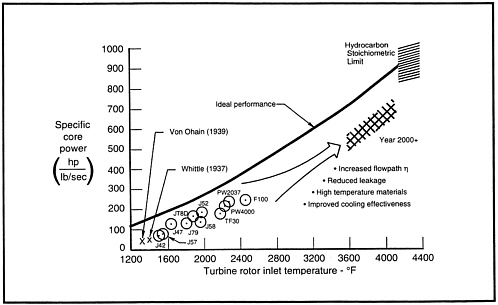
Figure 4-1 Improving Core Performance of Turbopropulsion Systems. Source: Koff, 1991.
will be lower than the ideal, industry expects that a concentrated technology effort could achieve an increase in core power of 2.5 over current production engines within the next 20 years.
The trend toward higher specific core engine power through technology advances is the key to the configuration design of fighters, military transports, strategic aircraft, and commercial aircraft, because they all use technologically similar core engines to develop the gas power for their propulsion systems.
Air breathing engines fall into three basic flight regimes: subsonic, supersonic, and hypersonic. These are discussed in the following subsections.
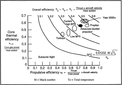
Figure 4-2 Trends in Overall Efficiency of Subsonic Turbopropulsion Systems Indicating a Target Goal in 2000+ for High Efficiency. Source: Koff, 1991.
Subsonic Commercial and Military Transport Engine Development
The “final frontier” in conventional subsonic propulsion is represented by the cross-hatched region in Figure 4-2. Industry is developing three basic types of engines to reach this goal for commercial passenger, heavy cargo, and military transport applications:
-
high bypass ratio (five to nine) direct-drive turbofans that produce up to about 90,000 pounds of thrust;
-
gear-drive turbofans (some with reversing pitch blades for thrust reverse) that produce up to about 120,000 pounds of thrust and use
-
slim-line nacelles to minimize interference drag with the wing-pylon installation; and
-
ultra-high bypass ratio (40 to 60) unducted propulsors that use reversing pitch blades for thrust reverse (the thrust produced by these engines is dependent on application).
For bypass engines (also referred to as turbofans, as opposed to turbojets, which have zero engine bypass), the nacelle air flow is split into two separate streams. The outer (bypass) stream flows through the fan, while the inner stream flows to the core engine, which produces the engine's power. The ratio of the fan bypass flow to the core engine flow is defined as the engine bypass ratio. At constant core engine power, fan bypass pressure ratios are reduced to accommodate high engine bypass ratios, and this lowers the velocity of the jet exhaust. For subsonic flight, lower jet velocity is desirable, because it reduces jet noise and improves propulsive efficiency, which decreases specific fuel consumption (SFC).
Higher thermal efficiency (ηt) and propulsive efficiency (ηp) result in higher overall efficiency (ηo), which is the product of ηt and ηp. Commercial engine developers use higher compression pressure ratios and higher turbine temperatures to increase core power and thermal efficiency, and they use higher bypass ratios and lower jet velocities to increase propulsive efficiency and reduce noise.
The advanced core engine technologies required to increase performance as projected in Figure 4-1 are being actively pursued with both industry and government funding. To reach the goals shown in Figure 4-2, significant technological advances are also required for the large propulsor, which includes the fan (fixed or variable pitch), gear drive, and nacelle. Progress in moving from the best of current engines to further-improved higher bypass engines (ηo>0.40) depends on the ability of the propulsion industry to make the required investment.
Supersonic Commercial Engine Development
NASA's High Speed Research program is working to overcome technical barriers (noise, emissions, and economics) associated with the development of a supersonic commercial transport. This program will develop the advanced technologies required for a high speed civil transport, which is currently projected to operate at Mach 2.0– 2.4 and an altitude of 55,000–60,000 feet. Arnold Engineering Development Center is already positioned to play a key role in meeting the propulsion test requirements for this effort. Ejector/diffuser incorporation into the center' s Aeropropulsion Systems Test Facility will provide the required altitude simulation capability.
Military Engine Development: Subsonic, Supersonic, and Hypersonic
Military engine technology is concentrating on:
-
low observables (radar and infrared);
-
vectoring nozzles (pitch and yaw);
-
direct lift coupled with lift fans;
-
higher thrust-to-weight ratio;
-
supersonic cruise using higher-energy core engines to drive higher fan pressure ratios; and
-
production of derivative engines by using the technology base to decrease development and production costs.
Military airlift engine programs will most probably adapt advanced commercial engines to provide increased range and payload.
During the past 10 years, most hypersonic technology funding has focused on the Mach 0 to 25 National Aero-Space Plane program. A significant redirection of this program is in progress. Studies are continuing to define Mach 3 to 5 air breathing engines for hypersonic applications, which may be needed in the twenty-first century. The 1989 report of the Air Force Scientific Advisory Board report identified the “wind
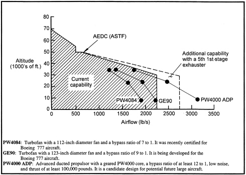
Figure 4-3 Comparison of Exhauster Capability of the Aeropropulsion Systems Test Facility and New Bypass Engines. Source of data: Pratt & Whitney, General Electric, and Arnold Engineering Development Center.
tunnel in the sky” (i.e., a research aircraft) as the only “test facility” for high Mach (8 to 15) flight. Work is still in progress to identify realistic and practical methods of ground testing air breathing supersonic combustion ramjet (scramjet) engines beyond Mach 7.
For the future, propulsion fuel sources other than petroleum-derived fuels will undergo intensive investigation. These initiatives may require special facilities, and major national facility planning efforts need to stay current. The nuclear propulsion option, as an example, could become a practical reality sometime during the next 30 to 50 years.
PROPULSION FACILITY REQUIREMENTS
Figure 4-3 shows that the current Aeropropulsion System Test Facility at Arnold Engineering Development Center is adequate for altitude testing of the newest generation of high-bypass engines, such as the PW4084 and GE90. However, a 40 percent increase in flow capacity might be required to handle the next generation of ultra-high-bypass, gear-driven propulsor engines such as the PW4000 Advanced Ducted Propulsor (ADP). These engines could be certified after the year 2000—if the aircraft manufacturers develop new, larger aircraft that require such engines. A Pratt &
Whitney geared-fan ADP demonstrator engine in the 50,000 pound thrust class that uses a medium-size PW2037 core was tested in 1993 at the Pratt & Whitney West Palm Beach ground test facility and at the 40-foot × 80-foot free jet wind tunnel at NASA's Ames Research Center. The advanced ducted propulsor engine shown in Figure 4-3 represents a geared 12 to 1 bypass ratio configuration that uses the larger PW4000 core engine.
The nature and timing of upgrades to the Aeropropulsion Systems Test Facility are heavily dependent on the launch of a new large aircraft requiring engines with significantly higher air flow. Implementation of facility upgrades for these larger subsonic engines would take four to eight years, so there is time to “wait and see” before deciding how to proceed. The addition of another exhaust compressor, at a cost of approximately $50 million, would increase the air flow capability of the Aeropropulsion Systems Test Facility to 2,750 pounds per second, as shown. This would fill part of the altitude test gap for future generations of subsonic high bypass engines. Arnold Engineering Development Center has identified other upgrades to the Aeropropulsion Systems Test Facility that would be needed to provide air flow up to 3,500 pounds per second. Cost estimates for these upgrades are on the order of $500 million.
Finding 4-1. Current propulsion facilities in the United States are world class and adequate to meet current and near-term test requirements.
Recommendation 4-1. Communication between the government agencies that operate national aeropropulsion facilities and industry should be continued to assure propulsion facility readiness relative to future requirements. In particular, the ASEB concurs that the study proposed by the NFS should be conducted.
REFERENCES
Koff, B.L. 1991 . Spanning the Globe with Jet Propulsion . American Institute of Aeronautics & Astronautics (Paper #2987) . William Littlewood Memorial Lecture Presented at AIAA Annual Meeting and Exhibit . Washington, D.C.
NASA (National Aeronautics and Space Administration) . 1992 . Final Report: Industry/DoD/Academia/NASA Workshop on Airbreathing Propulsion Facilities . NASA Lewis Research Center . August 7, 1992 . Cleveland, Ohio : NASA.
NRC (National Research Council) . 1988 . Review of Aeronautical Wind Tunnel Facilities . Aeronautics and Space Engineering Board, NRC . Washington, D.C. : National Academy Press .
NRC. 1992 . Future Aerospace Ground Test Facility Requirements for the Arnold Engineering Development Center . Aeronautics and Space Engineering Board, NRC . Washington, D.C. : National Academy Press .
USAF Scientific Advisory Board . 1989 . Requirements for Hypersonic Test Facilities . Department of the Air Force . Washington, D.C.


