
Steep and Breaking Faraday Waves
L.Jiang, M.Perlin, W.Schultz (University of Michigan, USA)
Abstract
This paper examines the dynamics of steep to breaking standing waves on deep water generated by Faraday resonance. Physical experiments are compared with simulations by a two-dimensional spectral Cauchy-integral code. At larger forcing amplitude, we have observed experimentally a steep waveform with a double-peaked crest, while simulation of the same forcing condition results in a sharper crest (Jiang et al., 1996). Increasing wave steepness leads first to a double-plunging breaker at the dimpled crest, then to more violent breaking in three recurrent modes (period tripling): sharp crest with breaking (A) → dimple or flat crest with breaking (B) → round crest without breaking (C). Nonlinear interaction between the fundamental mode and second temporal harmonic determines both the steep and breaking waveforms. Geometric features of the breaking wave are discussed, especially the extremely-large wave amplitude and sharp crest angle in mode A. Based on the periodicity of the flow, energy dissipation is directly estimated by integrating the support force as a function of the tank displacement. It is found that the breaking event increases the total dissipation in the system by about 100%. Large dissipation occurs during modes A and B due to spray, air entrainment and plunging.
Introduction
Synthetic Aperture Radar (SAR) images are often brighter near ocean features such as currents, shelves, and slicks that cause wave reflection. Since the backscattering of microwaves by the sea surface is sensitive to the curvature of surface features as well as Bragg periodicity, these strong SAR returns may be caused by higher surface curvature known to occur in standing waves that can be more peaked than their progressive wave counterparts. Therefore, accurate representation of steep and breaking standing waves, or more generally counterpropagating, periodic waves, is an essential feature required in the interpretation of SAR images. An even more complex phenomena: wave breaking, directly influences the specular and Bragg scattering. Since counterpropagating waves are very common in both open sea and coastal regions, their breaking mechanisms are crucial to wave modeling, e.g. (deep water and shoaling) wave breaking criteria, and energy dissipation. To this end, the breaking standing wave and its energy dissipation serve as a good model to study.
In the absence of viscous dissipation, a solution has been obtained by Penney & Price (1952) for standing gravity waves on the free surface of deep water. Their solution describes a standing wave with a sinusoidal shape at modest amplitudes to one with a more peaked crest and flatter troughs (c.f. figure 1) at higher amplitudes. With further increase in wave steepness to 0.218, their analysis appears to reach a limiting waveform with a crest angle of 90°. Schwartz & Whitney (1981) determined that the maximum wave steepness H/λ is 0.197 by expansion and 0.208 by analytic continuation, less than 0.218. Here, H is the peak-to-peak wave height and λ is the wavelength. A numerical investigation by Schultz & Vanden-Broeck (1990) showed that the surface tension had to be included to obtain waves as steep as predicted by Penney & Price (1952) and that the 90° crest angle conjecture was flawed. With surface tension, the steepest waves had a crest sharper than 90° or had a bulbous protuberance.
The standing-wave form of Penney & Price has been observed experimentally (Taylor 1953) and numerically (Vanden-Broeck & Schwartz 1981). Nontheless, the uniqueness of their solution is still undetermined. Their approach is only valid when resonance between different harmonics can be “avoided” (Tadjbakhsh & Keller 1960); symmetry in space and time is also a vital assumption in the success of a higher-order expansion by Schwartz & Whitney (1981). Recently, multiple forms of small-amplitude standing wave are discussed by Bryant & Stiassnie (1994) based on the Zakharov equation approach.
Taylor (1953) generated standing waves by simultaneously oscillating two hinged vertical paddles. Standing waves can also be excited by vertical oscillation through subharmonic resonance (Benjamin & Ursell 1954, Miles & Henderson 1990). Since the Faraday experiment ensures spatial periodicity by laterally fixed endwalls, this approach was adopted by Jiang et al. (1996) to study the Faraday resonance and nonlinear standing waveforms. According to the linear theory, the standing wave amplitude
Ai(t) is governed by a Mathieu equation,
(1)
where
(2a, b)
and
(3)
Here, ωf is the forcing frequency, f is the forcing amplitude. Subsequently, we use 1/k=λ/2π as the length scale and ![]() as the time scale, where λ is the characteristic wave length and g is the gravitational acceleration. In equation (3), ωi is the natural frequency for the ith spatial mode with wavenumber ki=i and dimensionless capillary number κ=σk2/ρg. The subharmonic resonance corresponds to p ≈ 1, i.e. ωf ≈2ωi. To excite the fundamental mode with one wavelength in the tank (k=k1=1), the forcing frequency must satisfy ωf ≈2ω1=2ωN. This forcing frequency eliminates the sloshing mode, thereby preserving the spatial symmetry about the tank centerline.
as the time scale, where λ is the characteristic wave length and g is the gravitational acceleration. In equation (3), ωi is the natural frequency for the ith spatial mode with wavenumber ki=i and dimensionless capillary number κ=σk2/ρg. The subharmonic resonance corresponds to p ≈ 1, i.e. ωf ≈2ωi. To excite the fundamental mode with one wavelength in the tank (k=k1=1), the forcing frequency must satisfy ωf ≈2ω1=2ωN. This forcing frequency eliminates the sloshing mode, thereby preserving the spatial symmetry about the tank centerline.
One notable result of Jiang et al. (1996) is that for larger wave steepness, unexpected flat and dimpled crests appear in the physical experiments while the numerical simulation presents a wave with much sharper crest. (The dimpled crest feature is seen in the numerics but for a different phase.) These intricate wave forms are not described by any standing-wave model. They are strongly asymmetric about the peak in time and only emerge at finite amplitudes.
The main theme of this paper is that the new standing wave leads eventually to breaking with period tripling in the physical experiments. Steep and breaking wave profiles are quantified by a non-intrusive optical system. At sufficiently large forcing amplitude, a steep wave with a dimpled crest generates two plungers breaking to each side of the tank centerline. Increasing the forcing amplitude further leads to period-tripling: breaking every two of three waves in a three-wave cycle. The dynamics of both steep and breaking standing waves are related to the interaction between the fundamental mode and it temporal second harmonic. To estimate the viscous dissipation and dissipation due to breaking, we present the first direct measurements based on the periodicity of the breaking events and accurate force measurements. Before presenting some preliminary results, we first describe briefly the method we use to measure wave dissipation.
Principle of wave dissipation measurement
For nonbreaking waves, experiments with a fixed forcing frequency and forcing amplitude can be divided into three stages: (1) initial state when the tank is oscillating but no wave growth is observed; (2) intermediate state when the wave amplitude grows to a maximum and then slowly decays to a finite amplitude; (3) the final periodic state when the limit-cycle amplitude of the Faraday wave remains constant. Using a load cell located between the shaker and the tank, we can measure the time history of the support force during these three stages. The measured force is integrated with respect to the tank displacement to yield the work done by the shaker on the system. The wave dissipation can then be estimated as described below.
The total energy (work) input to the system is transformed into wave energy, wave dissipation and mechanical work. Here, mechanical work includes bearing dissipation, friction and other energy losses that are unrelated to the fluid motion in the tank. During stage 1, the wave surface remains horizontal so both wave energy and wave dissipation are negligible. The measured work per unit wave period represents mechanical work only. During stage 2, part of the work done by the shaker is converted into wave energy. The measured work in stage 3 should equal the mechanical work plus the wave dissipation as a periodic wave field exists. As both forcing frequency and amplitude are constant in the experiments, and the center of the water body is fixed relative to the oscillating tank, the mechanical work in stage 3 is the same as that determined in stage 1. The wave dissipation ΔE is then determined by ΔE=Wtotal–Wmech.
Since this technique is based on the balance between energy input and energy dissipation, it only applies to periodic wave fields. Breaking-wave dissipation would be difficult to estimate because of the irreversible breaking process. Fortunately (also unexpectedly), the breaking waves in our experiments are periodic! At a forcing amplitude that first initiates breaking, double plungers appear (stage 4), but the waveform, once established, remains temporally and spatially periodic. At larger wave steepness (i.e. larger forcing), the dimpled waveform evolves into three different, but three-wave periodic breaking modes (stage 5): the most violent breaking mode, a sharp-crest wave with upward jet (A), occurs every three periods, followed repeatedly by a dimpled waveform with plunging breaking (B), and a round-crest mode (C). The energy dissipation during the three-wave periodic breaking is then estimated by calculating the average work every three periods in stage 5.
Numerical method
As in Jiang et al. (1996), we use the Cauchy integral method to simulate two-dimensional standing waves. In potential flow, the periodic free surface on the deep water can be conformally mapped to an approximate unit circle. The Lagrangian form of the kinematic and dynamic conditions are applied on the free surface:
(4)
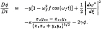
(5)
Here, D/Dt represents the material derivative. The complex potential w(ξ)=+![]() iψ is solved on the free surface ξ=x+iy and w* is the complex conjugate of w(ξ).
iψ is solved on the free surface ξ=x+iy and w* is the complex conjugate of w(ξ).
The subscripts represents the derivative of x and y with respect to s, a free-surface arclength parameter. To compute a Faraday wave, vertical oscillation is included as an effective acceleration. Measured damping coefficients γ are chosen to simulate physical experiments.
The principle-valued Cauchy integral equation
(6)
is discretized to solve for w(ζk) at the kth node, where α is the included angle. In the present scheme the integrand is expressed as a Cardinal function at the singularity and we evaluate the derivatives spectrally (Schultz et al. 1994). The algebraic equations are solved iteratively by GMRES (Saad & Schultz 1986) and a 4th-order modified Hamming predictor-corrector method is used for marching in time. All simulations presented use 64 nodes in the horizontal direction with an error tolerance of 10 –10 for time marching and iterative matrix solving.
Numerical (“zigzag”) instabilities occur for very steep waves. Then, we include an additional dissipation term γ1![]() sss in (5), where γ1 is at most about 1% of γ. In the present application, it is more effective in suppressing the higher-mode numerical instability than other attempted filtering techniques.
sss in (5), where γ1 is at most about 1% of γ. In the present application, it is more effective in suppressing the higher-mode numerical instability than other attempted filtering techniques.
Experimental apparatus
The inner dimensions of the rectangular glass tank are 600 mm long, 60 mm wide and 483 mm deep. The operational water depth is approximately 300 mm. With negligible lateral vibration (less than 3% of the vertical oscillation), this 10:1 tank aspect ratio ensures that the excited waves are two dimensional and symmetric in space (ωN=1.611 Hz). The tank is fixed to a programmable shaker that is best suited to operate in low frequency range: 0.5 Hz to 5.0 Hz. The control system includes a Macintosh computer with National Instruments' LabVIEW software, data acquisition boards, and a transducer for the vertical displacements of the tank.
Wave measurements
Spatial surface profiles are obtained by a laser-sheet measurement technique (Perlin et al. 1993). Figure 2 shows the imaging system, including a 5 Watt Argon-Ion laser; attendant optics and a high-speed, 8 bit video system with intensified imager. We use a spherical lens to focus the laser and a cylindrical lens to expand the laser beam into a sheet. The laser sheet is introduced from above the water, parallel to the front glasswall. It illuminates the central plane of the tank with a thickness less than 1 mm at the still water level. Fluorescent dye (fluorescein) is added to the water to brighten the liquid such that there is a jump in light intensity at the free surface. In some experiments, due to the complex nature of the breaking wave, we also use silver-coated hollow spheres (10µm diameter) as seeding particles to better illuminate the entire central plane.
We use a Kodak Ektapro CID intensified imager with controller to record the wave profile and use the Ektapro EM 1012 recorder for storage. The image is composed of 239 horizontal pixels by 192 vertical pixels. To capture the entire surface, we use a 50 mm camera lens on the intensified imager and the camera is located at 8 m from the tank. Its optical axis is oriented perpendicular to the laser sheet and at about a 15° angle with respect to the mean water surface (to remove any obstructing influence from the meniscus on the front glass wall). Using a precise target shows no significant image distortion in either direction. The average image resolution is 2.66 mm/pixel and the measurement error is about one pixel.
The images are recorded at 50 Hz through 250 Hz and transferred to computer via a standard GPIB interface. An edge-detection program identifies the wave profile from each image after a running-average smoothing is employed. The excellent repeatability of the profile measurements is demonstrated in Jiang et al. (1996).
To avoid surface contamination, the tank is scrubbed before and after each use with ethyl alcohol. Our treated water is de-ionized, carbon-adsorbed, and filtered to maintain a surface tension of 72 dyn/cm, close to that for pure water. The surface tension decreases to about 71 dyn/cm after the addition of fluorescein. By comparing with images taken by an 8 mm camera without dye present, we verified that the small change in surface tension does not cause a change in the wave profiles.
For the time history of surface elevation, we used a capacitance-type wave probe with an outside diameter of 1.6 mm positioned at the horizontal center of the tank. The measurement error is less than 1% of the wave height. The probe and feedback signals are low-pass filtered using two Krohn-Hite model 3342 analog filters with a cutoff frequency of 30 Hz. Then, the feedback signal is subtracted from the probe signal to obtain actual surface elevation.
Force and dissipation measurements
The dissipation measurement technique mentioned in the introduction is now fully discussed. The support force is measured by an OMEGA LCCA-100 load cell (strain gauge) placed between the platform and the tank. Its accuracy is: nonlinearity<0.03% of full scale, hysteresis <0.02% full scale, and non-repeatability<0.02% full scale. The load cell has a maximum capacity of 445 N, sufficient for the 294 N water and tank. The tank is guided vertically by six rollers (two on the front, two on the sides and two on the rear) to reduce lateral displacement. A Tektronix PS503A provides the 15 V DC power supply for the load cell, while the dynamic force signal is amplified by a Tektronix AM502 differential amplifier with a DC offset for the static load. A 200 gain (maximum dynamic force =27 lbs) is used to cover the range of forcing amplitude in our experiments.
The force signal is filtered by Krohn-Hite 3342 filters. There are higher harmonics evident in the 20 Hz to 25 Hz range that are attributed to the natural vibration mode
of the tank and shaker. These high-frequency components contribute to the total mechanical dissipation and should not be ignored. Therefore, the cut-off frequency of the low-pass (butterworth) filter is set at 100 Hz for both the force and displacement signals. The signals are then sampled at 300 Hz.
The instantaneous force is integrated with respect to tank displacement using Simpson's rule. The integrated work per wave cycle has a 7% standard deviation during stage 1 and a 2.5% standard deviation during stages 3 and 4. For the three-mode breaking wave, stage 5, the standard deviation for one wave period increases to more than 20% due to the unsteady nature of the breaking event. However, the deviation is reduced to less than 10% for the work per three wave periods, in agreement with the recurrence of the breaking events.
Steep standing waves
The experimental Faraday waves are similar to Penney & Price (1952) for moderate wave steepness, as in Figure 3(a). These waves are approximately symmetric in time, i.e. η(x,t)=η(x,–t) where a crest occurs at x=0, t=0. (spatial symmetry is preserved in all nonbreaking waves.) However, the waveform changes for large wave steepness.
Steep Faraday waves are obtained by either increasing the forcing amplitude (Figure 3b) or decreasing the forcing frequency (Figure 4). In both situations, flat and dimpled crests appear in the forced standing waves when the wave steepness H/λ exceeds 0.15. The temporal symmetry is obviously broken for waves with the dimpled crest as shown in figure 5. The wave crest is more peaked in figure 5(a) when the central elevation is increasing. After achieving the maximum wave profile, the dimpled crest remains as the central wave elevation decreases (figure 5b).
These salient features, namely the dimpled crest and broken temporal symmetry, are intimately related to the interaction between the fundamental mode and its second harmonic in time (Jiang et al., 1996). The phases of the first and second harmonic are defined as θ1 and θ2, measured relative to the frequency ω1=ωf/2. Amplitudes of the first two harmonics are a1 and a2 respectively. In the solution of Penney & Price (1952), the two harmonics are completely in phase (θ2–2θ1=0) and the second harmonic is small (a2/a1<0.03). Figure 6 presents the wave height (peak-to-peak elevation at the tank center), amplitude and phase of the first two harmonics from the wave-probe measurements. The dimpled crest corresponds to reduced wave height and increased second harmonic amplitude. More importantly, the phase difference θ2–2θ1 jumps when the dimpled crest first appears. For small forcing, the phase difference is still small, consistent with the observation of approximate temporal symmetry. However, increasing nonlinearity leads to a different phase between the first two harmonics, causing both temporal asymmetry and dimpled crest.
Jiang et al., (1996) show the parametric space where steep waves with flat or dimpled crest and breaking waves are observed. These waveforms exist over a wide range of frequency detuning and forcing amplitude. However, the numerical simulation reveals another steep wave form that does not resemble the waves with dimpled crest. Figure 7 shows the simulated Faraday wave with a forcing amplitude of 4.0 mm and forcing frequency of 3.22 Hz. It is strongly asymmetric in time and contains increased second harmonic. The phase difference between the first two harmonics is large, but has opposite sign compared with experiments. Therefore, the crest at the maximum position is sharply peaked, not dimpled.
The similarity and differences between numerics and physical experiments indicates that multiple forms of steep standing waves may exist. We can only speculate that under external forcing, the “resonance ” or interaction is very sensitive to the damping mechanism and frequency detuning. Since we only simulate the dissipation with Rayleigh damping, it could affect the phase difference and eventually changing the standing wave form.
Breaking standing waves
Gentle breaking
In Taylor (1953), the tank aspect ratio was 2.17 and the extreme standing waves were three-dimensional. In our experiments with a tank aspect ratio of 10:1, the waves remain two-dimensional up to incipient breaking, corresponding to H/λ ≈ 0.216. Figure 8 shows the limiting waveform with small breaking, where the forcing frequency and amplitude are 3.17 Hz, 4.04 mm. The maximum surface elevation is about 75 mm at either of the two protuberances at the dimpled crest, even though the surface elevation at the centerline only reaches 60 mm. Small ripples are generated around the two peaks in the dimpled crest. This is probably due to the high local curvature of the surface. Since the wave crest is more peaked when the central elevation is increasing, a spiller forms at the center when the crest changes from a peaked crest to a dimpled one (figure 8a,b). As the standing wave attains its maximum elevation at the tank centerline, two small plunging breakers forms to each side of the dimpled, but relatively flat crest. Shown in figure 8(c,d), these two plungers break outward from the centerline.
Three-mode breaking: spray and splash
The gentle breaking mode is unstable when the forcing amplitude is further increased. A series of images are taken at 50 Hz for a forcing amplitude and frequency of 4.6 mm and 3.20 Hz (figures 9–11). After several cycles of transition, period tripling follows. It first evolves into a distinct mode (A): the wave elevation reaches 140 mm, with a sharp crest angle—less than 45° (figure 9a). After reaching its maximum elevation at the centerline (0.20 s), the free surface elevation decreases, but the jet ejected at the crest lags behind, forming free water drops in a column. The jet then collides with the water surface, first forming a crater.
Then a rebounding jet and entrained air (bubbles). Significant acoustic energy is generated at this instant. The downward jet and the impinging process is shown in figure 9(b). The detected wave profiles show clearly a significant increase in the wave height and the sharp crest angle. Further evolution of mode A to a “rightward” or “leftward” breaker is discussed below.
This violent breaking mode A is followed by a wave form similar to that with a dimpled or flat crest (mode B), shown in figure 10. (Note that we have not separated the sets of images by the exact underlying wave period T=0.625 s, nor have we presented an entire three-wave period sequence.) Splashes, remnants of the impinging process, are obvious in the first frame of figure 10(a). The rebounding jet at the tank center lasts more than a half wave period, from 0.44 s in figure 9(b) to 0.76 s in figure 10(a), creating turbulent motion at the wave crest. The stronger double plungers to each side of the crest (0.72 s) enhance dissipation in the entire wave field. Slight spatial asymmetry at the crest is observed in the detected wave profiles. Mode C (figure 11) follows mode B with a smooth wave profile similar to Penney & Price (1952). We call it the round-crest mode. No energetic breaking occurs in this stage. Mode A reappears with high wave elevation, spray and splash after mode C, forming a recurrent cycle with a three-wave period.
The same sequence of breaking occurs at the two ends of the tank with a phase difference of one and a half periods. The air-entrainment process then occurs twice in a three-wave period. However, the maximum elevation is not as high as that at the center of the tank (1.04 s in figure 10b,d); jets are only ejected occasionally when the crests are at the two ends; and the subsequent splash is less intense.
The wave profile is essentially two-dimensional in mode A, although it has a sharp crest. In figure 12, a perspective view of the wave is shown in a photograph taken from the upper-left corner of the oscillating tank. The photograph covers more than a half wavelength, with the sharp crest at the left side of the image (with strong light refraction). Except for some small perturbations, the standing wave is uniform along the tank-width direction.
Although the first sharp crest forms of an upward jet in mode A, it can also develop into a large plunger with its crest listing to one side. The appearance of an upward jet or plunger is random. Four frames of a “rightward” plunger are shown in figure 13. A “leftward” plunging breaker (figure 14) is captured with both seed particles and dye in the water (As a better view of the entire wave field is realized than with only fluorescent dye.) In mode B, the post-breaking double plunger slide down to each side of the dimpled crest in less than 0.1 s (figure 15), creating turbulence locally near the surface. The remnant air bubbles are also visible at the wave center. As shown in figure 11, mode C has the least breaking, and neither bubbles nor turbulent surface motions are observed in figure 16.
Recurrent breaking and second harmonic
Recurrent breaking in three distinct modes is exhibited at larger forcing amplitude and extreme wave steepness. Even though we cannot reproduce the recurrence in our numerical simulation, the breaking modes A and B are similar to the steep wave form in numerical and physical experiments respectively. Mode C with a round crest closely resembles the Penney & Price (1952) solution. As shown in the analysis of the dimpled waveform, when the second harmonic has relatively large amplitude, different phase angles between the second harmonic and the fundamental mode introduce different wave forms: a zero phase difference produces waveforms similar to that of Penney & Price (1952); a wave with a dimpled crest has a positive phase difference θ2–2θ1 between 90° and 180°; a sharp-crested waveform has a negative phase angle θ2–2θ1 ≈ –40° in the numerical experiments. Therefore, the three modes in the breaking events are strongly connected with the interaction between the first and second harmonics.
Here, we present the time series obtained by a wave probe to illustrate the connection between periodic breaking and the second harmonic. The wave elevation y(t) at a fixed position can be expressed as
When period tripling occurs, the amplitudes a1,2 and the phases θ1,2 are function of a longer time scale 3T, where T=4π/ωf is the period of the first harmonic. From our data analysis, the frequencies of the first and second harmonics are indeed ![]() and ωf. Using complex demodulation (Bloomfield, 1976), we obtain the accurate modulation of amplitude a1,a2 for each harmonic and their phase difference θ2–2θ1. The phase difference is only allowed to be between 0° and 360°.
and ωf. Using complex demodulation (Bloomfield, 1976), we obtain the accurate modulation of amplitude a1,a2 for each harmonic and their phase difference θ2–2θ1. The phase difference is only allowed to be between 0° and 360°.
For the nonbreaking wave in figure 17, the demodulated first-harmonic amplitude reaches a steady value after 80 s. During wave growth, the second harmonic first grows, then decays to less than 1 mm, its phase angle is about 300°. As the first harmonic settles down to a steady amplitude, the second harmonic amplitude a2 increases to above 5 mm and its phase angle jumps to 180°, corresponding to the appearance of a dimpled crest in the waveform. At the end of the record, the wave reaches steady state and the small oscillations in a2 suggest instability. However, at this forcing amplitude, the dimpled crest observations persist for more than 10 minutes.
Figure 18 shows the transition from nonbreaking to three-mode breaking at 4.57 mm forcing. Due to the slight spatial asymmetry at the wave crest, the wave probe placed at the tank center does not always record the maximum wave elevation (140 mm in mode A). Before breaking, the phase angle exhibits the same trend as in figure 17. Once breaking occurs, there are small modulations in a1 and a large modulation in both a2 and their phase difference. An enlarged record is shown in figure 19 from 100 s to 120 s. The largest elevation corresponds to a maxima in a1, but not a2. The modulation of a2 is locked to the modulation in a1. The modulation of phase difference θ2–2θ1 is
about 140°, corresponding to recurrent modes A to C. Interaction between the first and second harmonics explains the three distinct breaking modes, as shown in the strong modulation of phase angle and the phase lock between a1 and a2.
Energy and dissipation in breaking standing waves
In this section, we are primarily concerned with the dissipation associated with the steep standing wave and dissipation due to breaking. In the current Faraday wave experiments, we only consider three control parameters: wavelength λ (limited by the tank configuration), forcing frequency ωf and forcing amplitude f. Two other parameters, wave amplitude a and natural frequency ωN can be determined by the above three parameters. Therefore, the dimensionless dissipation rate ε can be expressed as
7
where ΔE is the dimensional energy loss in a period and b is the tank width.
Figure 20 shows the surface elevation envelope and the power measured as work per wave period. Wave growth is accompanied by large oscillation in the total work expended by the shaker. The largest average work per period is in stage 5: three-mode breaking.
We also observe that the work per cycle is related to the dissipation mechanisms during the three-period breaking. Here, we estimate Δ E(t0) in a one-wave-period window centered at t0. There is about a 6.4 Hz oscillation in ΔE(t) that is possibly due to the mechanical vibrations. To determine the modulation, a low-pass filter is applied to the (integrated) work with a cut-off frequency of 3 Hz. The measured work per wave period, shown in figure 21, has two peaks in each three-wave cycle. The first maximum ΔE does not corresponds to the maximum elevation (mode A). Rather it occurs slightly less than one period later. The second peak in Δ E occurs one and a half periods later. As discussed above, the primary mechanisms of dissipation are the impinging jet and the ensuing air-entrainment that lags by a half period the maximum wave elevation. Following the energy loss in this process, there should be increased energy input, corresponding to the first peak in ΔE. Since the same dissipation process occurs exactly one and a half periods later (at the two ends of the tank), the second peak in ΔE is as expected.
Four different forcing frequencies: 3.18 Hz, 3.20 Hz, 3.22 Hz and 3.24 Hz are used in breaking-wave experiments. At each frequency, we increase the forcing amplitude and observe the limit-cycle wave amplitude until breaking occurs. Figure 22 summarizes the wave amplitude for these experiments. For nonbreaking waves, there is a relatively linear relationship between the excited wave amplitude and the forcing amplitude. When the amplitude increases to 60 mm, breaking occurs. Due to the difference in the three breaking modes, the wave amplitude in an arbitrary mode has considerable scatter.
The total wave dissipation is presented in figure 23. For the 3.18 Hz and 3.20 Hz experiments, the dissipation rate ε slowly increases with forcing amplitude although at a lower rate than expected. Some dissipation data appears to decrease just below the forcing amplitude that causes breaking. The standard deviation in the data is about 20%–30%. For breaking waves that are excited with higher forcing amplitude, the dissipation rate jumps from an average value of 0.0052±0.001 to 0.0114±0.0015, an increase of 100%. The same increase in energy dissipation is recorded in figure 23(b), with slightly more scatter. The dissipation rate increases from 0.004±0.001 to 0.008±0.001 for 3.22 Hz forcing, and increases from 0.0028±0.001 to 0.0055±0.0015 for 3.24 Hz forcing. Once breaking occurs, a further increase in the forcing amplitude does not cause an increase in the breaking-wave dissipation. Therefore for steep waves, the dissipation in one period is about 5% of the wave energy (based on the linear estimate ![]() ), and breaking increases the dissipation to 10% of the total energy.
), and breaking increases the dissipation to 10% of the total energy.
The breaking-wave dissipation can be estimated by subtracting the averaged (viscous plus contact-line) dissipation for nonbreaking waves from the total dissipation. Shown in figure 24, the breaking-wave dissipation is largest for the lowest forcing frequency 3.18 Hz, and is decreasing for higher frequencies. We believe this frequency dependence is directly related to the effect of forcing frequency on the jet formation (spray) and the colliding intensity (splash). With higher forcing frequency, the sharp crest has less time to develop, thus less drops and air entrainment occurs. This frequency dependence therefore reinforces our claim that the primary dissipation mechanism is the air-entrainment and the jet reentry process.
Concluding Remarks
Here, we have observed previously unpredicted steep standing waves: flat and dimpled crests appear in the forced standing waves for larger wave steepness H/λ ≈ 0.15. The maximum steepness for the new wave forms exceeds 0.21. The strong second harmonic and temporal asymmetry indicate internal resonance among the first and second temporal harmonics. The two-dimensional Faraday waves first break with two overturning plungers to each side of the crest.
Increasing the forcing amplitude or decreasing the forcing frequency causes the wave with dimpled crest to become unstable. It leads to period tripling with three breaking modes: mode A: sharp crest forms, the upward jet or the large plunger to each side impinges on the wave surface, creating bubbles and a strong rebounding jet; mode B: the waveform has a flat or dimpled crest, two outward plungers forms to each side of the crest; mode C: the crest is round and smooth, significant breaking is absent. The recurrence of mode A → B → C forms a three-period cy-
cle that occurs for all forcing frequencies with sufficient forcing amplitude. The strong modulation in the first two harmonics is investigated using complex demodulation of our wave-probe signal. More importantly, the large variation in phase angle demonstrates the interaction between the first two harmonics that directly causes the three distinct breaking modes.
We provide direct measurement of the energy dissipation due to viscous and contact-line effects and breaking. Instantaneous force measurements are integrated with respect to the tank displacement to provide the energy input to the system. The breaking wave increases the total wave dissipation by about 100%. Variations in the work per wave period is attributed to the strength of the different breakers: mode A provides the largest dissipation because of the reentrant jet and air entrainment. Strong frequency dependence is also shown in the dissipation rate.
We show that the sharp crest with an upward jet has a crest angle less than 45°, sometimes even less than 30°. Using our laser-sheet measuring system, we can examine local features of the wave crest with an average resolution of 0.4 mm/pixel. Magnification of the crest region shows its structure and the sharp angle in figure 25. Each frame is approximately 35 mm by 60 mm. These steep waveforms and breaking modes can cause drastically different radar returns due to the wedge-scattering mechanisms.
Acknowledgments
This research was supported by the Office of Naval Research partially under contract number N00014–93–1–0867 and partially under the University Research Initiative Ocean Surface Processes and Remote Sensing at the University of Michigan, contract number N00014–92-J-1650.
References
BENJAMIN, T.B. & URSELL, F. 1954 The stability of the plane free surface of a liquid in vertical periodic motion. Proc. R. Soc. Lond. A 225, 505–515.
BLOOMFIELD, P. 1976 Fourier Analysis of Time Series: An Introduction. New York: Wiley, 118–149.
BRYANT, P.J. & STIASSNIE, M. 1994 Different forms for nonlinear standing waves in deep water. J. Fluid Mech. 272, 135–156.
JIANG, L., TING, C., PERLIN, M. & SCHULTZ, W.W. 1996 Moderate and steep Faraday waves: instabilities, modulation and temporal asymmetries, submitted to J. Fluid Mech.
MILES, J.W. & HENDERSON, D.M. 1990 Parametrically forced surface waves. Ann. Rev. Fluid Mech. 22, 143– 165.
PENNEY, W.G. & PRICE, A.T. 1952 Finite periodic stationary gravity waves in a perfect liquid. Phil. Trans. R. Soc. Lond. A 244, 254–284.
PERLIN, M., LIN, H. & TING, C. 1993 On parasitic capillary waves generated by steep gravity waves: an experimental investigation with spatial and temporal measurements . J. Fluid Mech. 255, 597–620.
SAAD, Y. & SCHULTZ, M.H. 1986 GMRES: a generalized minimal residual algorithm for solving nonsymmetric linear systems. SIAM J. Sci. Stat. Comput. 7, 856– 869.
SCHULTZ, W.W., HUH, J. & GRIFFIN, O.M. 1994 Potential energy in steep and breaking waves. J. Fluid Mech. 278, 201–228.
SCHULTZ, W.W. & VANDEN-BROECK J.M. 1990 Computations of nonlinear standing waves. Bull. Amer. Phys. Soc. 35, 2290.
SCHWARTZ, L.W. & WHITNEY, A.K. 1981 A semi-analytic solution for nonlinear standing waves in deep water . J. Fluid Mech. 107, 147–171.
TADJBAKHSH I. & KELLER J.B. 1960 Standing surface waves of finite amplitude. J. Fluid Mech. 8, 442–451.
TAYLOR G.I. 1953 An experimental study of standing waves. Proc. R. Soc. Lond. A 218, 44–59.
VANDEN-BROECK J.M. & SCHWARTZ, L.W. 1981 Numerical calculation of standing waves in water of arbitrary uniform depth. Phys. Fluids 24, 812–815.
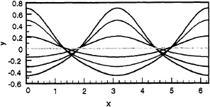
Figure 1. Standing wave profiles every 1/12 period in a half period based on the third-order truncation of Penney & Price (1952). The length scales are chosen to make the primary wavenumber unity. Wave steepness, H/λ=0.186. The vertical scale is twice as large as the horizontal scale.
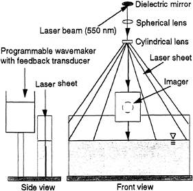
Figure 2. Experimental setup of the tank, lighting and imaging system. The spherical lens has a focal length of 1000 mm, the cylindrical lens has a focal length of 6.35 mm.
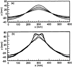
Figure 3. (a) Maximum wave profiles with crest at center for 3.32 Hz forcing in physical experiments. The five forcing amplitudes are 2.65 mm, 2.87 mm, 3.17 mm, 3.49 mm and 3.87 mm. (b) Forcing frequency is 3.20 Hz, forcing amplitudes are 1.61 mm, 1.92 mm, 3.17 mm, 3.49 mm and 3.88 mm. Wave amplitude increases with forcing amplitude. The vertical scale is twice as large as the horizontal scale.
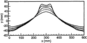
Figure 4. Maximum wave profiles from physical experiments, all at forcing amplitudes of 3.5 mm. Five forcing frequencies are 3.32 Hz, 3.29 Hz, 3.26 Hz, 3.23 Hz, and 3.20 Hz. Wave amplitude increases with decreasing forcing frequency. The vertical scale is twice as large as the horizontal scale.
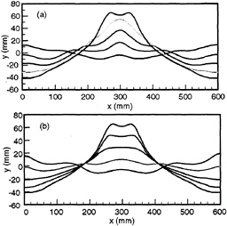
Figure 5. Experimental wave profiles with (a) increasing and (b) decreasing elevation at the centerline. Forcing frequency is 3.23 Hz, forcing amplitude is 3.85 mm. The time interval between each profile is about 0.04 s. The vertical scale is twice as large as the horizontal scale.
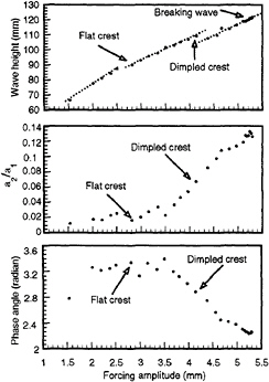
Figure 6. Wave height, the ratio of the second-harmonic amplitude to the first-harmonic amplitude, and the phase angle θ2–2θ1. Forcing frequency is 3.22 Hz.
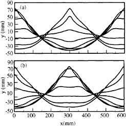
Figure 7. Numerical simulation of the forcing amplitude of 4.0 mm and forcing frequency 3.22 Hz. Surface tension is 72 dyn/cm. (a) Decreasing central elevation (b) Increasing central elevation. The wave profiles are graphed every 1/12 period. The vertical scale is twice as large as the horizontal scale.
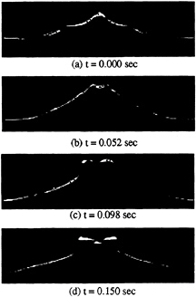
Figure 8. Small breaking at the dimpled crest. Forcing frequency is 3.17 Hz, forcing amplitude is 4.04 mm.
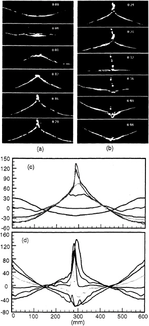
Figure 9. The observed wave form during mode A with a time interval of 0.04 s. Forcing amplitude is 4.6 mm, forcing frequency is 3.20 Hz. The detected wave profiles for column (a) and (b) are graphed in (c) and (d). In (c), (d), the vertical scale is 1.5 times the horizontal scale. The numbers shown in the images represent time in s.
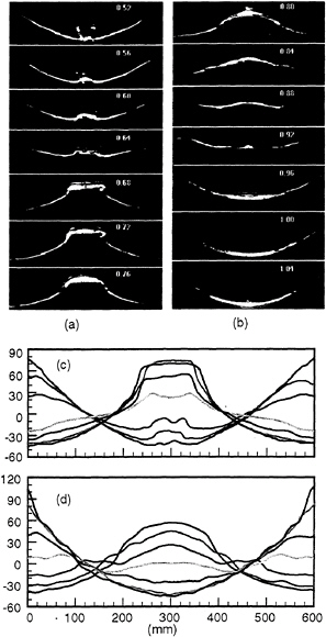
Figure 10. The observed wave form during mode B (following figure 9b) with a time interval of 0.04 s. The numbers shown in the images represent time in s. Forcing parameters are the same as in figure 9. The detected wave profile is graphed in (c) and (d). In (c), (d), the vertical scale is 1.5 times the horizontal scale.
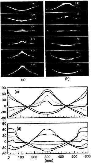
Figure 11. Mode C and detected wave profiles. Forcing parameters are the same as figure 9. In the detected wave profiles, the vertical scale is 1.5 times the horizontal scale.
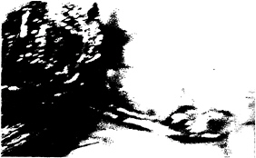
Figure 12. A photograph of mode A with the sharp crest it the left of the image. Forcing paramters are the same is in figure 9.
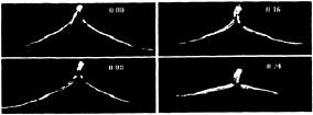
Figure 13. Breaking wave with “rightward” jet. The maximum wave profile is presented at t=0.00 s. Same forcing parameters are the same as in figure 9.
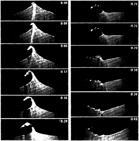
Figure 14. Mode A with “leftward” plunging breaker. The forcing amplitude is 4.6 mm, forcing frequency is 3.20 Hz. Note that the time intervals between frames are not the same.
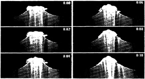
Figure 15. Double plunger to each side of the dimpled crest. Same forcing condition as in figure 14. The bulbous center at t=0.04–0.08 s is caused by the rebounding jet. The entrained air bubbles are clearly visible in the last four frames (under the crest).
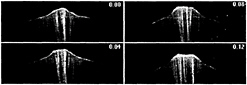
Figure 16. Mode C without breaking (same forcing condition), maxixum elevation occurs at t=0.04 s.
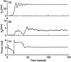
Figure 17. Complex demodulated wave probe signal at forcing frequency 3.20 Hz, forcing amplitude 4.15 mm. (a) Amplitude of the first harmonic (b) amplitude of the second harmonic (c) phase angle θ2–2θ1.
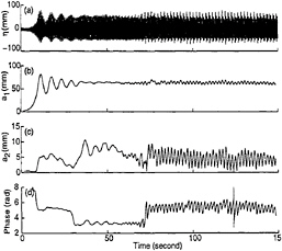
Figure 18. Complex demodulated wave probe signal at forcing frequency 3.20 Hz and forcing amplitude 4.57 mm. (a) Surface elevation (b) amplitude of the first harmonic (c) amplitude of the second harmonic (d) phase angle θ2–2θ1.

Figure 19. Same as previous figure.
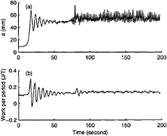
Figure 20. (a) Envelope of surface elevation and (b) work per wave period for forcing frequency 3.20 Hz and forcing amplitude 4.57 mm.
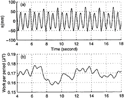
Figure 21. (a) Elevation at the centerline of the tank and (b) dimensional dissipation rate for forcing frequency 3.22 Hz, forcing amplitude 4.55mm.
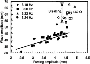
Figure 22. Amplitude of nonbreaking (solid symbols) and breaking (hollow symbols) waves for different forcing frequenicies.
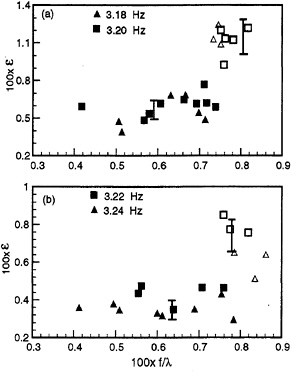
Figure 23. Dimensionless dissipation rate for nonbreaking (solid symbols) and breaking waves (hollow symbols). The lower and upper error bars reflect typical standard deviations for nonbreaking and breaking waves.
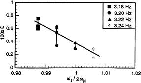
Figure 24. The breaking-wave dissipation vs. frequency detuning for four different forcing frequencies.
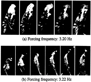
Figure 25. The crest structure at the maximum wave elevation of mode A. (a) Forcing amplitude is 4.57 mm. Time interval between each frames is 0.008 s. (b) Forcing amplitude is 4.6 mm. Time interval between frames is 0.016 s. The vertical scale is the same as the horizontal scale.
DISCUSSION
E.Palm
University of Oslo, Norway
It is an interesting and important topic which is discussed in this paper. In spite of this, the available, pertinent literature on the topic is very limited. The paper is of special value since it reports experimental as well as numerical results.
The main outcome of the numerical computations is displayed in Fig.6, which shows the mean second-order forces acting on the submerged body as functions of ω2b/g1, for three different values of the pycnocline thickness, δ. As expected, it is found that for sufficiently long waves the pycnocline layer is of no importance if the body is situated from this layer. The figures suggest that the waves do not feel the pycnocline layer if kδ< about 0.5 (k incoming wave number), roughly speaking. It would be of interest to see also the data for other forms of the elliptic body, for example, a circular form or a flat plate.
The experimental and numerical results are compared in Figs. 7 and 8. It is surprising that in Figs. 7a and 7b a fair agreement is obtained for the horizontal force whereas the values for the vertical forces are more than 100% different. The authors believe it is due to nonlinear effects which obviously may be important. It is seen that for Figs. 7a and 7b the values of the second-order forces computed by the two-layer models are in reasonable agreement with those obtained from the three-layer model. This suggests that it would be of interest to apply a two-layer time-dependent nonlinear program to this problem to study the forces. Such programs exist.
AUTHORS' REPLY
NONE RECEIVED


