
7
Computer Simulation for Storage Systems Design and Integration
INTRODUCTION
Hybrid vehicles, even ones without the additional electric loads of a combat vehicle, represent complex systems for which computer simulation is manifestly the best means of sizing the various components. This is particularly true when evaluating trade-offs among various means of storing energy, such as batteries and flywheels. Component sizes are readily varied in software, but they are varied at great cost in time and money when in hardware. Computer simulation and modeling are also the norm when engineering individual components of a hybrid system such as power converters or pulse-forming networks for weapons systems.
It is equally manifest, for such complex systems, that simulation and modeling must be verified through hardware emulation. The CHPS program recognized the importance of both activities when it pursued the dual avenues of software simulation via the “CHPSET” code set and hardware emulation via the Systems Integration Laboratory (SIL); (see Chapter 1).
CHPSET contains a hierarchy of codes, from a broad-brush system representation useful for size/weight trade-off studies, to a detailed electrical circuit model for designing individual electrical components. The set includes purpose-written codes, commercial software, and a mission database. Table 7-1 outlines CHPSET.
TABLE 7-1 Description of CHPSET Components
|
Tool |
Description |
|
CHPSPERF |
Performance modeling in MATLAB/Simulink, Saber, and other environments |
|
CHPSIZE |
Sizing and packaging methodology code written in Visual Basic |
|
CHPSEMI |
High-frequency modeling of EMI environment |
|
VITMAC |
SAIC-developed multi-physics code for steady-state and transient thermal-fluid response with companion FEA codes |
|
Pro/ENGINEER |
Commercial three-dimensional solids modeling code for rendering and packaging |
|
Operational profiles |
Mission profiles and vignettes |
Table 7-2 outlines some vehicle components now or previously incorporated into SIL.
TABLE 7-2 Hybrid Vehicle Hardware Components Incorporated into the Systems Integration Laboratory
|
Component |
Description |
|
Engine/generator |
Caterpillar 3126B engine with induction generator 750VDC, 280 kW |
|
Traction motors |
750 VDC, 100 kW continuous, 300 kW intermittent |
|
Battery |
Nickel cadmium, 300 to 900 VDC (reconfigurable), 50 kWh |
|
Battery |
Li-ion, 530 VDC, 30 kWh |
|
Flywheel/generator |
750 VDC, 2 kWh, 160 kW |
|
Pulse power |
100 kJ, 10 KV ETC pulse-forming network and power supply |
|
Cooling system |
Full vehicle emulated cooling system |
|
Control system |
Fully computerized, distributed system capable of running mission scripts autonomously |
SIMULATION AND MODELING NEEDS
Simulation and modeling stand somewhat apart from the committee’s other workshop topics, which focus on hardware and technologies. Focusing on a particular software set (CHPSET) tended to narrow the scope of the discussions, as may be seen from the following list of discussion topics:
-
The necessity that CHPSET be validated using SIL, and possibly data from the hybrid HMMWV and Scout vehicles;
-
The difficulty of modeling cooling airflow, particularly through combat grillwork, and the necessity that this flow be emulated in hardware;
-
Linkage of the CHPSET codes in order to automate the design process;
-
Incorporation of appropriate CHPSET tools into a virtual battlefield environment to allow interactive mission development;
-
Expanded consideration of environmental factors (heat, cold, rain, mud, terrain roughness, and so on), given that they affect such factors as tractive effort, battery performance, and turbine performance;
-
Inclusion of more user options (such as modeling parallel hybrid systems, and conventional vehicles) in the executable version of CHPSET;
-
User documentation to accompany the executable package;
-
Incorporation of CHPSET into failure modes and effects analysis (FMEA); and
-
Construction of design-specific, skid-mounted emulators for use in verification and testing of future combat system (FCS) hardware.
In this list, items 1, 2, 6, 7, and 9 are highly specific and may stand as recommendations without further comment.
With respect to linkage of the CHPSET codes (item 3), the committee offers the following “vision” of how such linkages might be implemented. Modeling and simulation of vehicle systems require both a solid modeler and a system simulator, and these need to be linked and consistent. By embedding performance simulations in the solid model components, creation of a solid model could automatically create a performance simulation usable for examining the vehicle’s electrical, thermal, and automotive performance.
Because hybrid power systems by their nature involve multiple disciplines, the information needed will have to come from areas with which the user is not necessarily conversant. A common expanded solid model database is one method to control and transfer information between system designers and component designers that can be both accurate and timely, resulting in better vehicle simulation configuration control.
The source of the information in the database is different depending on whether the system is being used in a forward-looking design study or in a fieldable system design. In the first case, the system should know enough about the components to generate the information required for the simulation. For example, the designer should be able to say he or she wants a 100-kW, PM motor that is 0.30 m in diameter and 0.20 m long and have the simulation (1) give an indication of the technical feasibility of the machine and (2) generate generic resistances, inductances, and so on, necessary to model the machine. The user should be able to override this information, should better information be available.
Where there are existing pieces of hardware from a vendor, the vendor should provide a solid model of this hardware that can be dropped in the solid model and a “black-box” mathematical model that describes that piece of hardware and its interfaces (electrical, mechanical and software) to the outside world. This technology is available and being used in other applications. Vendors routinely provide either two-dimensional or three-dimensional mechanical models with mass properties of their hardware. Electrical component vendors routinely supply both datasheets and circuit simulation (e.g., SPICE) models of the electrical properties of their hardware. With a standard interface that fully describes the frequency and fidelity of the models, it is conceivable that they could provide “digital” datasheets describing the electrical, mechanical, and thermal interfaces of their hardware for use in combat vehicle simulations.
Model validation is critical if the modeling and simulation system is to be widely used and disseminated. Model validation needs to be performed at three different levels:
-
The numerics level. The simulation must be based on robust numerical procedures and processes that are well documented at the limits of applicability.
-
The component level. This can and should be handled at the vendor level when there are specific pieces of hardware. If vendors will be supplying “black-box” models, then they will also be responsible for ensuring that the models they supply faithfully replicate their machines.
-
The system level of validation. For CHPS, validation at this level must make use of the System Integration Lab, skid-mounted emulators (as noted in item 9, above) and fielded hardware to ensure that the models operate as expected.
Discussion item 4, above, addresses the potential for using CHPS vehicle simulators to assist in establishing an understanding of how best to use the vehicle during the various modes of operation with power management as the principal consideration. For example, overusing a weapon system during a short duration of time could create a situation in which the vehicle would not have enough power reserves to overcome the resistance forces associated with maneuvering over challenging terrain in the remainder of the projected mission path. Vehicle-level simulators exist for training soldiers how to effectively operate specific vehicle systems, such as the HMMWV (“Hummer”), Bradley Fighting Vehicle, and M1 Abrams Main Battle Tank. Generic vehicle-level simulators such as the Close Combat Tactical Trainer (CCTT) exist as well. CCTT can be set up and programmed to approximate most known and future vehicles in both peacetime missions and realistic combat scenarios. The total energy balance, including drive systems, weapons systems, and other energy needs, is a critical issue for these vehicles. Greater emphasis should be placed on the importance of this type of simulation for hybrid vehicles and comparison with standard vehicles and standard weapons systems. This information will be vital in understanding options and making trade-offs in design.
In integrating CHPSET models into a higher-level simulation, the committee believes that consideration should be given to the Joint Modeling and Simulation System (JMASS). JMASS is a standard engineering/engagement-level simulation support environment that allows modelers to build, configure, assemble, execute, and process representations of real-world systems into simulations. The Army recognizes the potential benefits of this standard system and has made a commitment to support its development and adopt it for use to support evolving and future Army modeling and simulation (M&S) requirements. Quoting from a recent paper1:
This engagement/engineering level M&S system breaks new ground in the realm of Object-Oriented (OO) digital constructive simulation. While other M&S systems deliver a complete, integrated simulation as their end product, JMASS instead provides an architecture, interface standards and a set of GUI-based tools, which can be used to build models to those standards and integrate these models with the architecture components to in turn build simulations. While other
|
1 |
Meyer, Robert J. ASC/AAJ. 2000. Joint Modeling and Simulation System (JMASS), What it Does .… and What it Doesn't. (JMASS JPO). Online. Wright Patterson AFB. Available at http://www.redstone.army.mil/amrdec/jmass/library/JMASS_SIW_Paper.doc. Accessed December 2002. |
M&S systems have their evaluation mechanisms embedded and for the most part pre-determined, JMASS forces applications to define those mechanisms in re-usable, re-configurable components. This challenges potential users to thoroughly understand and decompose their problems and at the same time offers them extraordinary flexibility in implementing solutions to those problems. While other M&S systems leave interfaces as an "exercise for the reader," JMASS uses powerful code-generation techniques to lock-in those interfaces, virtually assuring code reliability and stability.
Discussion item 5, above, consideration of environmental factors, arose from lengthy discussions of the NATO Reference Mobility Model (NRMM) as a well-validated, widely used model of the road/vehicle interface. The resistance forces that CHPS vehicles encounter will drastically vary depending on the mission. Realistic mission-related considerations need to be applied when defining the resistance force input data for CHPSET. NRMM and other related software tools, such as a route analysis tool kit, could provide the realistic mission-related resistance data required for CHPSET.
NRMM is a comprehensive analytical model designed to objectively evaluate the on-and off-road mobility of ground-based vehicles. It uses physics-based algorithms with vehicle-terrain interaction relationships that are primarily empirical. NRMM predicts go/no-go and speed as basic outputs based on input data that include detailed characterizations of the vehicle and terrain, considerations of weather and seasonal effects, and considerations of other speed limiting constraints related to human factors and powertrain-independent vehicle characteristics. NRMM is typically used to analyze the mission-related performance of wheeled and tracked vehicles for operations in realistic theaters of operation that can cover vast areas of terrain.
The most commonly used mission consideration is based on predicting an effective mission speed, referred to as the Mission Rating Speed (MRS). For the MRS, it is assumed that the vehicle may have to operate on any terrain unit in the theater of operation based on a predefined mix of primary roads, secondary roads, trails, and cross-country terrain that make up the vehicle’s mission profile. The mission profile is typically defined in the Operational Requirements Document for the vehicle. The MRS is essentially a wide-area, statistical measure of a vehicle’s maneuver effectiveness considering the total theater of operation. Other mission considerations have recently been made possible by the development of a route analysis tool kit. With the tool kit, realistic mission plans can be developed by laying out routes of operation on standard Defense mapping assets as illustrated in Figure 7-1. This technique provides for a more realistic measure of mission effectiveness and does not rely on a predefined mission profile.
NRMM predicts speed using the powertrain-dependent maximum tractive force versus speed curve, the maximum tractive force available from the terrain, the speed-reducing slip that will occur on the terrain, the motion resistance forces acting on the vehicle, and other powertrain-independent speed limiters, as illustrated in Figure 7-2. The model predicts the basic components used to determine these five major items for the vehicle in each of the many discrete terrain units (typically 100-meter by 100-meter) that make up
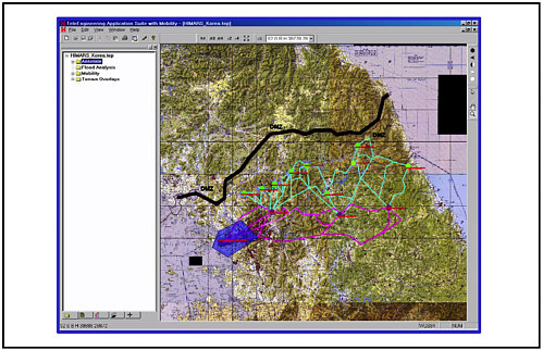
Figure 1. Mission plan for NRMM predictions using a route analysis tool kit Courtesy of Jody Priddy, U.S. Army Engineer R&D Center (ERDC).
the entire theater of operation for the mission. The resistance forces that are considered in NRMM include rolling resistance on pavement and in soil of varying type and strength, resistance due to climbing slopes, vegetation (i.e., tree) override resistance, obstacle override resistance, and resistance from traversing curves on roads and trails.
For typical applications of NRMM, the basic components of the five major items, such as the magnitude of the various resistance forces, are not catalogued for output. However, for special applications, the basic prediction components can be catalogued. For example, the resistance forces from the various sources associated with each terrain unit can be catalogued for output. This would allow output of resistance force versus distance (or time) tabulations for the vehicle operating in the mission-related theater of operation. This special application was demonstrated in a recent study in which ERDC used NRMM to assist the U.S. Marine Corps and the Defense Advanced Research Projects Agency in the design phase of the Reconnaissance Surveillance Targeting Vehicle (RSTV), which has in-hub electric drive.
In this effort, NRMM was used to characterize the power required to overcome the mission-related resistance forces acting on the RSTV. Various operating theaters and seasonal scenarios were used in the study to relate the effective mission resistance and associated power requirements for several mission concepts. In addition, ERDC developed a special technique for determining a resistance force associated with terrain
roughness. Terrain roughness is handled in NRMM as a human factors speed limit, but there would be an effective resistance force associated with traversing rough terrain. This additional resistance force is needed for the special application of using NRMM to define power requirements for CHPS vehicles.
SUMMARY
A summary of the technical challenges and opportunities discussed above for improvement of computer simulation for the design of storage systems and components is given in Table 7-3.
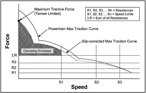
FIGURE 7-2 NRMM basic speed prediction methodology. SOURCE: Courtesy of Jody Priddy, U.S. Army Engineer R&D Center.
TABLE 7-3 Technical Challenges, Performance Metrics, and Research Priorities Associated with Computer Simulation for the Design of Storage Systems and Components
|
Component/System |
Technical Challenges |
Performance Metrics |
R&D Priorities |
|
CHPSET tool set |
Validation against available hardware |
Accurate simulation of hardware performance |
Validation using data from the Systems Integration Laboratory and possibly hybrid HMMWV and Scout vehicles |
|
Cooling airflow |
Modeling cooling effectiveness and cooling airflow, especially through combat grillwork |
Resemblance of emulation hardware to notional, demonstrator-level hardware |
Emulation of environmental factors Emulation using grillwork hardware |
|
Linkage of CHPSET codes |
Effective information transfer between system designers and component designers |
Fidelity of vendor-supplied models |
Development of a common, expanded solid model database |
|
|
Difficulty of modeling hardware provided by vendors |
Compatibility of models with CHPSET tools |
Vendors encouraged to provide solid models of their hardware, validated at the numeric, component, and system levels |
|
Incorporation of CHPSET tools in a virtual battlefield environment |
Understanding of power management during the various modes of operation |
Successful integration of a CHPSET model into a higher-level simulation |
Integration of CHPSET models into the Joint Modeling and Simulation System (JMASS) |
|
Consideration of environmental factors in CHPSET |
Need for realistic mission-related resistance data |
Successful incorporation of NATO Reference Mobility Model (NRMM) data into CHPSET |
Explore use of NRMM and related software tools such as a route analysis tool kit to generate input data for CHPSET |
|
User options in CHPSET code |
Need for comparative analysis capability involving other vehicle options |
Executable code user friendliness |
Expand executable CHPSET code to include additional user options such as parallel hybrid and conventional vehicles, with appropriate user documentation |
|
Incorporation of CHPSET codes into failure modes and effects analysis (FMEA) |
Enhancement of system reliability and mitigation of effect of component failures |
Risk priority numbers |
Identification of potential failure modes |


