
Appendix C
DAMAGE TO METAL BUILDINGS: A DETAILED ANALYSIS
Most of the observed damage to metal buildings can be grouped into the following categories, in order of their frequency of occurrence:
-
overhead door failures,
-
canopy failures,
-
damage to steel/masonry facade interface,
-
omission of bracing by contractor,
-
improper anchorage of columns,
-
strut purlin failures leading to catastrophic collapse of the end bay of the building.
The first five items have proved troublesome to the metal building industry from the very beginning; however, the cause is easily identified. Perhaps the most important factor that sets the preengineered metal building apart from the other forms of low-rise construction is the manner in which the product is engineered, fabricated, marketed, sold, and erected. Early on, the industry developed a method of doing business in which the building is sold, not directly to a customer, but through a franchised builder who usually acts as a general contractor providing erection service as well. Thus, on the positive side, design, drafting, and fabrication take place under the same ''roof'' and enable the manufacturer to "fine tune" engineering design and fabrication to achieve the optimum economy consistent with reliability. On the negative side, however, control over the design of components not supplied by the manufacturer (e.g., doors, facade, glazing, foundation details) and erection procedures in some cases may be lost to the engineer who designed the building.
The last item (failure of strut purlins) has been addressed in the industry's
new design manual (Metal Building Manufacturers Association, 1986), and hopefully the problem will soon be eliminated. Unfortunately, current building codes remain silent as to the correct combination of loads to be considered in the design of these structural elements.
Overhead Door Failures With the exception of large sliding doors for aircraft hangars, most doors used with metal buildings are not supplied or designed by the manufacturer. Historically, the performance of large overhead doors during severe winds has been poor. Building codes clearly require doors to provide the same wind resistance as components and cladding. Regrettably, experience tells us many builders knowingly, or unknowingly, disregard this requirement. In their defense it should be noted that, at present, no recognized standard test procedure exists to ascertain wind resistance of large door assemblages.
Recent research (Vickery et al., 1984) has served to quantify the role of internal pressure that may significantly increase the net uplift on the roof or outward loads on side walls (see Figure 4-20). Failures of doors enclosing areas of as little as 1 to 5 percent of the area of a windward wall may be sufficient to produce extreme internal pressure fluctuations. The 1982 alternative procedure of the Standard Building Code attempted to come to grips with this problem through provisions for "partially enclosed" buildings, although experience suggests these provisions were only rarely used. Figure 4-20 illustrates the increase in net wind loads on fasteners, purlins, and girts if it is assumed that the building envelope has been breached and a maximum increase in internal pressure occurs. Note that the fastener corner loads have increased from 66 to 75 lb/ft2 (14 percent increase) and purlin loads from 32 to 42 lb/ft2 (31 percent increase). A comparison with provisions in the 1974 revisions to the 1973 code is even more dramatic and suggests increases of 80 percent for purlins and 213 percent for fasteners. Adding these increases to the usually permitted one-third increase in allowable stress for load combinations including wind effects clearly uses up any normal factor of safety.
Although the majority of the thousands of metal buildings affected by Elena performed adequately, overhead door failures sometimes leading to progressive failures of roofs and walls were much too common in even relatively new construction (Figure C-1). In the aggregate, the largest percentage of damage to metal building systems due to Elena, and previous severe storms as well, can be attributed to this single problem—one which can obviously be easily addressed.
Canopy Failures Canopies should be designed to resist the uplift contributions from both upper and lower surfaces. Failures were observed that marred the otherwise satisfactory performance of a number of buildings
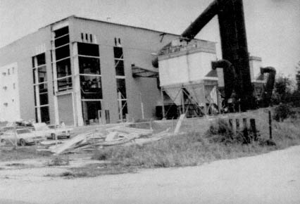
Figure C-1 Damage to cladding (side and leeward walls) of the Pascagoula Energy Recovery Facility resulting from overhead door failure.
(Figure C-2). Regrettably, canopies often receive only superficial design attention, as they are typically not supplied by the manufacturer and because the cost of repair or replacement is small. Fortunately, no case of canopies separating from the parent structure, becoming airborne, and constituting a hazard to human life and other property were reportS, although this has occurred in past storms. Interestingly, the data base developed at the University of Western Ontario (Davenport et al., 1977 and 1978) for the metal building industry constitutes the best available source of design information to address this all too common problem.
Damage to Steel/Masonry Facade Interface To achieve desired aesthetic effects, architects use masonry, wood, glass, aluminum, and copper to clad metal building systems. Unfortunately, it would appear that until very recently little attention has been given to the proper attachment of the masonry to the steel framework. In some applications, the building is first sheathed with the usual metal sheeting, and the masonry veneer is then attached by metal ties. All too often, this veneer was stripped from the walls by the high suction pressures during Elena's high winds (Figure C-3). Several failures were observed in which unreinforced concrete block walls collapsed. The block walls of the automobile dealership shown in Figure C-4 appeared to have been free-stand-
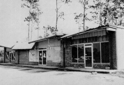
ing with only minimal connections to the steel framing. The steel skeleton (frames, purlins, and rod bracing) survived with little damage. Collapse of the walls may have been precipitated by loss of glazing and failure of a number of overhead doors, resulting in high internal pressure.
Some engineers (Ellifritt, 1984) suggest that the masonry must be designed to permit relative movement between the block and the rigid frames. The designer is hampered in this approach because current methods of analyzing building behavior to predict drift do not properly account for diaphragm and frame interaction of the roof and wall assemblages. In all probability, for example, the building shown in Figure C-5 would have behaved essentially as a box, shear-wall structure with the stiff roof diaphragm distributing lateral loads directly to the end walls. The actual lateral deflection of the frames could well have been only 10 to 15 percent of that calculated, assuming pure frame action in the absence of "skin behavior" (MBMA, 1986). The metal building industry is aware of this problem and is supporting research in this area.
Omission of Bracing and Improper Column Anchorage As noted previously, the franchised dealer may lose some control over the installation of bracing
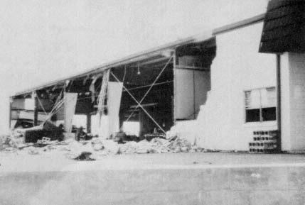
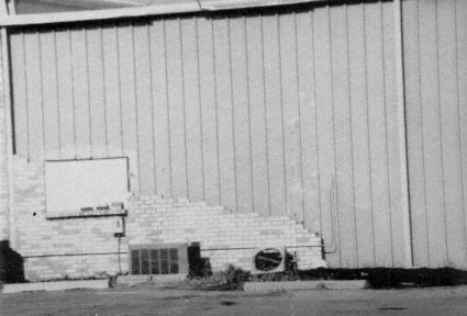
Figure C-4 Damage to unreinforced masonry wall enclosing metal building in Biloxi. Failure may have been precipitated by loss of large overhead doors. Steel framing was undamaged.
Figure C-5 Metal building clad with masonry veneer located in Gautier.
called for in building plans and column anchorage details that are normally not provided by the manufacturer. As more experience has been gained concerning the field performance of buildings subjected to high winds, these problems have tended to disappear in new construction. Some of the older buildings, however; were not properly designed to resist high-uplift forces, and failures were observed.
End Bay Failures A serious deficiency in some buildings designed in accordance with the earlier codes concerns the combined loading effects on strut purlins, as depicted in Figure C-6. The purlins must be capable of transferring the axial loads generated by wind action on the end walls of the building, in addition to resisting the high, localized bending loads produced as a result of suction on the roof surfaces.
A number of cases were observed in which the strut purlins buckled, leading to catastrophic failure of the entire end bays of the buildings. The furniture store shown in Figure C-7 exhibited this type of behavior. Failure was initiated by high internal pressure fluctuations from the loss of the glazing on the windward wall due to windborne debris; roofing material from adjacent upstream buildings was found in the interior of the building. Damage was limited to the first bay, and the building was returned to ser-
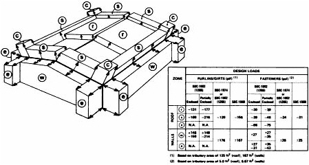
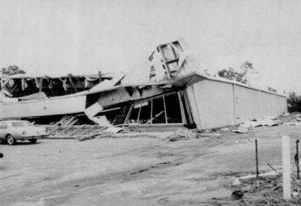
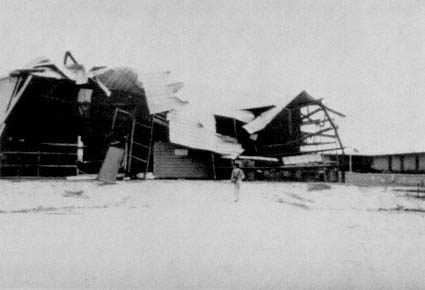
Figure C-8 End bay damage to preengineered building in Pascagoula.
Note new, undamaged metal building on right.
vice in a short time. Sensibly, the building was repaired with a facade more resistant to windborne debris.
Another building, which suffered the same fate, is shown in Figures C-8 and C-9. Note the light-gauge base plates that failed to resist the uplift forces on the columns. The vintage of this building is probably early to late 1950s; a current check of industry practice suggests that the minimum thickness of the column base plate used is 3/8 inch. A more recently erected building by the same manufacturer, adjacent to the building in Figure C-8, is shown in Figure C-10. This structure suffered no distress during the passage of Elena and was probably subjected to higher wind loading, since it is sited on a hill. Note the smaller glazed areas and the absence of overhead doors.
Building codes in use throughout the United States do not prescribe the actual combination of loads to be used in the design of strut purlins. This is because the appropriate data base has not yet been established from wind tunnel tests. The most recent edition of the low-rise design manual for the metal building industry (MBMA,1986) provides a caveat with regard to this design application but does not specify the loadings to be considered. Engineering judgment is required. One approach would be to consider a worst-case scenario in which the required axial load is assessed on the basis of main-framing coefficients coupled with bending load prescribed from
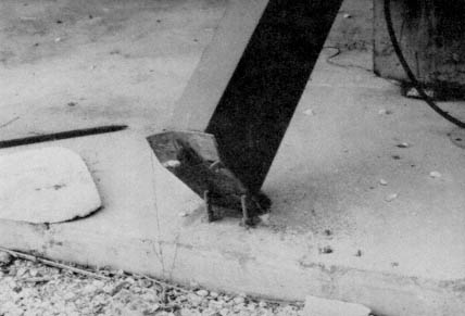
Figure C-9 Failure of column base plates of building in Figure C-8.
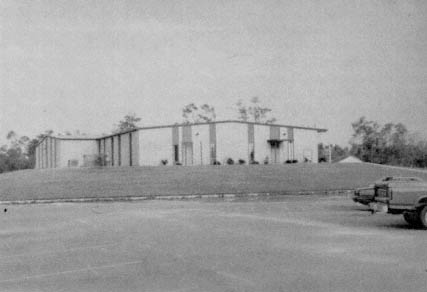
Figure C-10 New, undamaged, preengineered metal building located adjacent to building in Figure C-8. Note absence of overhead doors and large glazed areas. Building was sited in more severe wind exposure.
coefficients given for components and cladding. As the two effects do not occur for the same wind azimuth in this case, the approach would appear to be conservative. Perhaps a more realistic scheme would be to consider two load cases:
-
axial and bending effects based on main-framing coefficients, and
-
bending alone based on component and cladding provisions.
Hopefully, wind tunnel researchers will address this problem in the near future. It should be noted that this is only one of many design applications not specifically addressed in codes in which an element or structural assemblage is required to resist both main-framing and high, localized loads.


