
3
Payload Sensor Characteristics
The design of payload sensors (instruments) for Earth observation flows logically from the measurement requirements that have been established by the science and instrument teams. There is a straightforward process whereby the fundamental scientific questions to be answered lead to a set of measurement requirements that establish the point of departure for sensor design and trade-off studies. Trade-off studies assess instrument design alternatives that can produce the required measurements within the constraints set by fundamental physics, the state of the technology, and cost. Within these bounds, sensor designers work to minimize size, mass, and power requirements. Once established, these characteristics, in turn, determine the payload accommodation requirements. The sizing of the payload sensors(s) affects the design of a mission's entire space segment and establishes the scale (and therefore the cost) of the spacecraft and launch vehicle.
Chapters 4 and 5 of this report provide data showing that smaller satellite buses and smaller launch vehicles are available at lower cost (and capacity) than larger versions. It follows then that the smallest launch vehicle and smallest spacecraft bus that can accommodate a given mission sensor payload will generally yield the lowest mission space segment costs. Advances in sensor technology that can reduce instrument size, mass, and power consumption thus provide considerable leverage and are a frequent objective of sensor technology development efforts, which also aim at producing new or improved measurement capabilities and/or lowered costs. This chapter and Appendix B discuss the sensor design process and the potential for size, mass, and power reduction within the constraints of the fundamental physics that govern the desired measurements.
PAYLOAD DESIGN AND ACCOMMODATION REQUIREMENTS
The design process proceeds iteratively, as payload design engineers work with the scientific community to identify, challenge, and revise requirements that are driving cost, size, mass, and power. As the sensor design evolves, the requirements for accommodating the payload become apparent—that is, the mechanical, thermal, optical, and electrical interfaces that the spacecraft must provide in order for the payload to function as planned. Highlights of the process are illustrated in Figure 3.1.
The resulting interface requirements are then analyzed with the spacecraft engineers to arrive at a spacecraft and launch vehicle design that appropriately balances cost and risk. Box 3.1 categorizes interface, or payload accommodation, requirements.
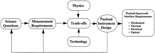
Figure 3.1
The payload design process generates requirements for accommodating the payload.
|
BOX 3.1 Payload Accommodation Requirements Mechanical
Thermal
Electrical
Optical
|
Specific accommodation requirements vary widely depending on the type of payload instrument, with high-resolution, broad-swath, electro-optical multispectral imagers being the most demanding in terms of size, mass, data rate, and pointing accuracy and stability. Pointing and stability is often a differentiating factor between spacecraft designed to carry communication payloads and those designed to carry remote sensing payloads, the latter typically having more demanding requirements (see Chapter 4).
CURRENTLY PLANNED SENSORS
A comprehensive suite of payload instruments is currently under development for the National Aeronautics and Space Administration's (NASA's) Earth Science Enterprise (ESE)—including those that will be placed on the
Earth Observing System (EOS) AM, PM, and Chemistry satellites and the Tropical Rainfall Measuring Mission Observatory. TOMS (Total Ozone Mapping Spectrometer) and SeaWiFS (Sea-Viewing Wide Field-of-View Sensor) are other key sensors in the ESE. Efforts are also under way to define the payload instruments and develop the technology for the National Polar-orbiting Operational Environmental Satellite System (NPOESS), the next generation of polar-orbiting meteorological satellites. The spacecraft launches and corresponding payloads planned for the ESE are summarized in Figure 3.2.
The payload instruments represented in ESE and NPOESS programs cover a remarkably wide range of functions and interface requirements. These instruments include electro-optical and microwave radiometers, spectrometers, imagers, sounders, and altimeters that range from extremely compact to quite substantial. For example, some of the space environment monitoring instruments planned for NPOESS occupy less than 0.001 m3 and have a mass of only 3 kg; in contrast, the three instruments composing the ASTER (Advanced Spaceborne Thermal Emission and Reflection Radiometer) and the MODIS (Moderate-Resolution Imaging Spectrometer), which are facility class instruments in the EOS program, have volumes and masses of 2.7 m3/421 kg and 2.0 m3/229 kg, respectively. Accommodation requirements for representative EOS and NPOESS sensors are tabulated in Table 3.1. In reviewing these data, it is evident that many payload instruments as currently designed could be flown on small satellites (100 to 500 kg); others are clearly unsuitable, even with advanced satellite buses that promise payload mass fractions of 40 percent or more.
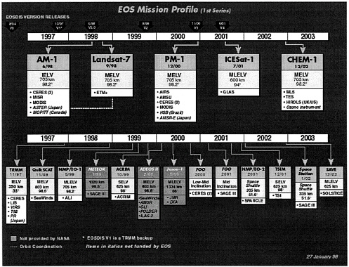
Figure 3.2
EOS mission profile (courtesy of NASA). Note that all acronyms are defined in Appendix E.
Table 3.1 Payload and Related Accommodation Requirements for Representative EOS and NPOESS Instruments
|
|
Sizea (mm) |
|
|
|
|
|||
|
Instruments |
L or vel. dir. |
W or Sun dir. |
H or nadir dir. |
Vol (m3) |
Power (watts) |
Mass (kg) |
Data Rate (kbps) avg |
Notes |
|
EOS INSTRUMENTS |
||||||||
|
AIRS |
1,397 |
775 |
762 |
0.83 |
156 |
256 |
1,440 |
|
|
ASTER |
|
|
|
|
421 |
463 |
8,300 |
|
|
VNIR |
580 |
650 |
830 |
0.31 |
|
|
|
|
|
SWIR |
720 |
1,340 |
910 |
0.88 |
|
|
|
|
|
TIR |
730 |
1,830 |
1,100 |
1.50 |
|
|
|
|
|
CERES |
600 |
600 |
576 |
0.21 |
50 per scanner |
47 per scanner |
10 |
|
|
MISR |
1,300 |
900 |
900 |
1.0 |
149 |
83 |
3,300 |
|
|
MODIS |
1,044 |
1,184 |
1638 |
2.02 |
229 |
163 |
6,200 |
|
|
MOPITT |
1,150 |
930 |
570 |
0.61 |
192 |
250 |
28 |
|
|
NPOESS INSTRUMENTS |
||||||||
|
IPO-Developed Instruments: Not-to-Exceed Values |
||||||||
|
VIIRSb |
1,320 |
1,290 |
1,380 |
2.35 |
200 |
300 |
8,000 |
0530 & 1330 Orbits |
|
CrIS |
640 |
450 |
470 |
0.135 |
81 |
91 |
1,500 |
1330 Orbit |
|
CMISb |
63,500 max stowed dim. |
TBD |
275 |
340 |
500 |
0530 & 1330 Orbits |
||
|
GPSOSb |
330 |
230 |
270 |
0.02 |
22 |
40 |
50 |
0530 & 1330 Orbits |
|
OMPS |
450 |
540 |
560 |
0.136 |
45 |
45 |
50 |
1330 Orbit |
|
SES |
TBD |
TBD |
TBD |
TBD |
100 |
40 |
50 |
0530 & 1330 Orbits |
|
Leveraged Instruments: Estimates for IPO Planning Purposes |
||||||||
|
ATMS |
700 |
600 |
400 |
0.168 |
66 |
85 |
300 |
1330 Orbit |
|
TSIS |
640 |
640 |
640 |
0.262 |
49 |
71 |
15 |
0530 Orbit only |
|
ERBS |
410 |
410 |
590 |
0.099 |
55 |
55 |
10 |
1330 Orbit only |
|
ALT |
|
|
|
|
98 |
|
|
Weight includes antenna; |
|
Electronics |
460 |
330 |
280 |
0.043 |
|
110 |
24 |
antenna dimension is a diameter. |
|
Antenna |
11,400 |
11,400 |
TBD |
|
|
|
|
0530 Orbit |
|
DCS |
|
|
|
|
70 |
66 |
NA |
|
|
Electronics 1 |
200 |
360 |
280 |
0.020 |
|
|
|
|
|
Electronics 2 |
200 |
310 |
280 |
0.017 |
|
|
|
DCS in 0530 & 1330 Orbits |
|
Electronics 3 |
200 |
310 |
280 |
0.017 |
|
|
|
|
|
Antenna |
50 |
50 |
230 |
0.0005 |
|
|
|
L-W dimension is a diameter. |
|
SARSAT |
|
|
|
|
46 |
70 |
NA |
0530 Orbit only |
|
RPU electronics |
390 |
280 |
200 |
0.022 |
|
|
|
|
|
SPU electronics |
310 |
280 |
200 |
0.017 |
|
|
|
|
|
Antenna |
80 |
80 |
650 |
0.003 |
|
|
|
L-W dimension is a diameter. |
|
NOTE: All acronyms are defined in Appendix E. NA = not applicable; TBD = to be determined. a These are Sun-synchronous satellites, Y-axis points in Sun direction. b VIIRS, CMIS, and GPSOS are also planned for launch on a European METOP (meteorological operational) polar satellite. The METOP isa joint undertaking of the European Organisation for the Exploitation of Meteorological Satellites (EUMETSAT), the European Space Agency (ESA), and their member states. |
||||||||
SENSOR COSTS
Intuitively, it would seem that payload sensors should account for a large proportion of a mission's space segment costs, since the measurements they make represent the mission's purpose, and the other space segment elements (satellite bus, launch vehicle) are really in service to the payload. In reality, payload costs are typically between 30 and 70 percent of the space segment total, with the variation depending on the complexity of the sensors, the nature of the mission (research versus operational), and the development state of the mission elements. This last factor involves the need for nonrecurring development costs. Research instruments are frequently burdened with such costs in order to employ the most current technology to gain enhanced performance; they subsequently must often bear the cost of more extensive characterization, calibration, and validation efforts. Operational payloads incur nonrecurring development costs to achieve long-lived, high-reliability designs, but then typically benefit from block buys where only the costs of manufacture, integration, and testing are incurred for subsequent units.
Operational sensors are often derived from successful research sensors and benefit from their already-paid-for development costs. Similarly, research sensors often benefit from extensive, separately funded technology development that precedes the actual sensor development program and is not booked against it. True sensor costs are hard to ascertain even for specific sensor programs. Sensors under development can only show estimates of costs. For completed sensors, costs are sometimes allocated to multiple accounts, which can further obscure actual costs.
The committee encountered these and other difficulties in trying to understand and compare the costs for EOS research sensors with their NPOESS counterparts. The most direct comparisons were possible for the programs' multispectral imagers (MODIS and VIIRS [Visible and Infrared Imaging Sensor]) and infrared sounders (AIRS [Atmospheric Infrared Sounder] and CrIS [Cross-track Infrared Sounder]), as shown in Table 3.2.
The data show that the target first unit costs for the operational NPOESS sensors are substantially lower than the actual costs of their EOS counterparts. One reason for this cost differential is that the first unit costs for the NPOESS sensors include those for the data processing algorithms, whereas the costs for the EOS sensors do not. The data also show that the recurring target costs for subsequent NPOESS sensors are much lower than for their EOS counterparts.1 Part of the anticipated reduced costs for the NPOESS sensors reflects (1) diminished requirements as a result of reduced capability (e.g., VIIRS has less on-board calibration capability than MODIS, and CrIS has fewer spectral channels than AIRS); (2) a more efficient, multiple-buy procurement process; and (3) prior development (of the EOS and other sensors) and advances in technology and processes. With proper funding to enable them, advances in sensor technology and processes should continue to improve performance, cost, size, mass, and power parameters to suit mission objectives.
FUTURE SENSOR DESIGNS: IMPLICATIONS OF ADVANCED TECHNOLOGIES
Size and Design Constraints2
The ''trade space" for the design and sizing of payload instruments is established by four types of constraints: fundamental, technological, mission, and programmatic (see Box 3.2). As technology development progresses in critical payload components and materials, the degrees of freedom available to the payload designer increase so that more efficient and capable instrument designs become feasible. There are limitations, however, because not all elements of a payload are amenable to miniaturization. While we can expect continued improvements in the size/mass/power efficiency of payload electronics, for example, the size of other subsystems—notably optics and radiative coolers—are set by first-order physics that are not subject to technological improvement. Even for subsystems and components that are driven by physics, improvements in materials and packaging techniques can
|
1 |
Although there are no plans to build a second AIRS unit given the cost of the first unit, it is likely that a second would cost considerably more than the $12.5 million recurring cost target for CrIS. |
|
2 |
The information in this section provides an overview of the physical limits on sensor sizing. Appendix C continues this discussion and examines in greater detail the prospects for building more compact sensors for EOS and NPOESS. |
Table 3.2 EOS and NPOESS Sensor Cost Comparisons
|
BOX 3.2 Four Types of Payload Design Constraints
|
significantly affect size/mass trade-offs. For example, relatively large apertures are feasible with small satellites by invoking deployable or inflatable technologies, although there are attendant costs and risks.3
Within the constraints outlined above, sensor design and size are determined by a complex trade-off among spatial, spectral, and radiometric performance. All three of these performance measurements are interdependent, and, barring compensatory design changes, each performance measure is improved at the expense of the others. Developing a design that balances all of these performance parameters while minimizing size, cost, and technical risk is the essence of sensor system engineering.
Fundamental Limits on Size
The physics of diffraction and radiometry's energy collection requirements establish the fundamental limits on aperture size. Aperture size, in turn, is often the single most important parameter in determining the scale of a remote sensing instrument. Such a general pronouncement has many exceptions, however; there are sensor designs, for example, in which the swept volume of a scanning mirror or the size of a passive radiative cooler becomes the dominant factor.
Technological Limits on Size
The theoretical performance limit on radiometric sensitivity provides a useful framework for examining the interdependencies among performance and design parameters. Radiometric sensitivity (signal-to-noise ratio) depends on the optical aperture area, the detector solid angle (spatial resolution), signal integration time, and spectral bandwidth, among other parameters, as noted in Figure 3.3.
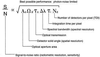
Figure 3.3
Factors determining detector signal-to-noise ratio.
Improvements in either spatial or spectral resolution thus come at the expense of radiometric sensitivity unless these are offset by a larger aperture, better optical transmission, or increased integration time. Improvements in technology can influence the relative attractiveness of these alternatives. For example, effective integration time (and hence radiometric sensitivity) can be increased by adding more detectors and slowing the effective scan rate or by using additional detectors to take multiple samples of the same point in object space and coherently summing the outputs—a process called time-delay integration (TDI). These strategies offer improved performance at the expense of added complexity in the detector arrays and associated signal processing electronics; on the other hand, technology improvements in these areas have made it possible to exploit such design strategies with relatively low cost and risk.
The foregoing discussion offers a good example of the way in which technology advances have led to changes in the design optimization process. In the 1970s, detector technology and signal processing electronics were less well developed, so intelligent designs of that era minimized the number of detectors via the use of scanning mechanisms and relatively large optical apertures. Now that higher density detector arrays and sophisticated signal processing electronics are readily available, aperture size can be (and has been) significantly reduced for many classes of instruments. Still, for imaging sensors of relatively high spatial resolution, aperture diameter is clearly the dominant sizing parameter because diffraction-limited performance is a fundamental physical limit that is not amenable to technological improvement. Technology advances have nonetheless made it feasible to design systems whose performance is close to theoretical limits.
Figure 3.4 shows the relationship between aperture diameter and spatial resolution (ground sampling distance) for different spectral wavelengths and altitudes.4 For example, an aperture diameter on the order of 10 cm is needed to provide 10 m spatial resolution from an altitude of 705 km. Curves such as these can be misleading, however, because "resolution" is not meaningful unless defined in terms of an equivalent modulation transfer function or point spread function. Indeed, there could be a four-to-one difference in aperture diameter for different sensors all purported to have the same spatial resolution, as denoted by the extent of the design range bar in Figure 3.4. Sensors at different points within that design range would exhibit substantial differences in performance. These differences arise from adopting different design approaches in balancing sensor subsystem performance.
Sensor designers can choose the governing factor that establishes the spatial resolution of an instrument: either the optics or the detector can become the limiting element. Three different design philosophies are illustrated in Figure 3.5. All three systems might claim to have 10 m spatial resolution, for example, because each of these designs uses a detector element that has a 10×10 m projection on the surface of Earth.
In the first case, performance is truly limited by the optical aperture: The diffraction-limited blur circle of the optics is the largest (dominant) component. This design point represents the lower extreme of aperture sizes in the design range shown in Figure 3.4. Such an approach extracts the most performance from a given aperture size. Because the detector size is much smaller than the optical blur circle, the resulting point spread function (the convolution of the optical blur and the detector's active area) is nearly the same as the optical blur alone. Note that in this case, however, it would be highly misleading to claim that the resulting sensor had a spatial resolution equal to the size of the detector. Rather, the equivalent size of a resolution element would be more like the size of the optical blur circle—about one-half the resolution claimed.
The second example in Figure 3.5 shows a design case that balances the optical blur circle and detector size so that they are approximately equal. This is the design point that corresponds to the center of the design range in Figure 3.4. The third example, with the smallest optical blur circle, corresponds to the largest aperture diameter within the design range. This design would have the best spatial resolution of the three alternatives, but it would also be the largest of the sensor designs.
Measurement Strategies and Mission Architectures
Payload sizing and the feasibility of employing small satellites depend as much on measurement strategy and architecture as on specific sensor technologies. Different approaches to partitioning measurements among different instruments and satellites can have significant effects on the size/mass/power of payload sensor designs and their corresponding host spacecraft. This becomes the classic trade-off between fewer, highly capable multipurpose instruments versus a greater number of smaller, simpler, more specialized instruments tailored for specific measurements.
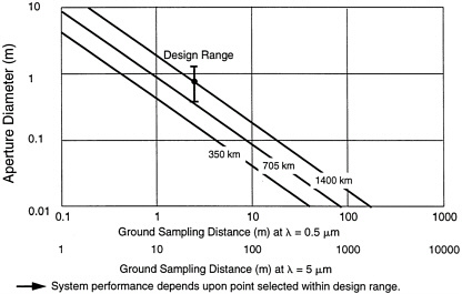
Figure 3.4
Diffraction dictates aperture size.
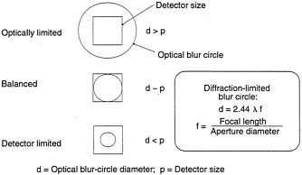
Figure 3.5
Different design approaches yield a 4:1 range in aperture size (or equivalently in focal ratio).
For example, MODIS, with its 36 spectral channels ranging from 0.405 µm to 14.385 µm, makes a variety of measurements that serve a broad array of applications including vegetation/biomass estimation, cloud cover, atmospheric sounding, and ocean color. These measurements could be acquired by two, three, or perhaps four separate, smaller sensors tailored for a specific application. Each of these smaller instruments could even fly on its own dedicated small satellite (or even smaller microsatellite), though the economic advantage of designing and building a proliferation of smaller sensors is not clear. Small satellite technology is at least an enabler that makes it feasible to address these trade-offs in search of a robust and economical solution to mission-level measurement needs.
SUMMARY
Sensor design should flow from measurement requirements and is best performed as an iterative process between designers and the science community within the constraints set by fundamental physics, the state of the technology, and cost.
The size of payload sensors affects the design of the entire space segment and establishes the scale of the spacecraft and launch vehicle. Through this relationship, the payload sensors exert substantial leverage over all space segment element costs.
It is often difficult to determine the actual costs of developing new sensors. Many development programs build on prior technology or sensor development efforts but do not account for these costs. Nevertheless, the National Oceanic and Atmospheric Administration anticipates lower costs for the NPOESS sensors compared with their heritage sensors on EOS. Lower costs might be expected due to the EOS development heritage, further advances in sensor technology, and more efficient procurements (e.g., multiple buys).
As currently designed, many—but not all—of the sensors planned for EOS and NPOESS satellites could be physically accommodated on small satellites in the 100 to 500 kg class. Chapter 6 provides a detailed analysis of the factors to be considered in determining whether it is cost-effective to distribute planned sensors on a larger number of satellite platforms. Larger, multipurpose sensors can be subjected to the classical analysis of the trade-offs in partitioning required measurements among several smaller sensors that could then be accommodated on several small satellites, although the economic advantage of doing so is not apparent.5
|
5 |
Similar architectural trade-offs are discussed in Chapter 6 at the spacecraft level. |


