
3
Mitigating Solutions for Wind Turbine Generator Effects on Marine Vessel Radar
STAKEHOLDER NEEDS AND CAPABILITIES
When navigating in congested waters, the ability for a vessel to maintain a clear operating picture of other vessels, potential hazards, and obstructions is paramount, and requires an effective use of a mix of visual lookout and electronic sensors. A clear and understandable radar picture can provide the capability to see beyond the limits of the human eye, and provide the mariner an enhanced ability to safely navigate, appropriately respond to potential collision avoidance scenarios, and reduce risks associated with operating in the marine environment.
As previously discussed within this report, the Marine Transportation System (MTS) is grappling with a large growth in the development of Offshore Renewable Energy Installations (OREI), such as wind farms. While the U.S. Coast Guard is seeking to provide the mariner safe access to ports by designating shipping safety fairways and traffic separation schemes throughout the MTS, the location of the OREI in relation to these proposed shipping lanes may still pose risk to marine navigation. The presence of wind farms coupled with the subsequent shipping safety fairways is expected to funnel large, offshore commercial traffic into designated maritime traffic lanes. This consolidation of maritime traffic routes offshore in the vicinity of wind farms could potentially congest maritime traffic in previously unrestricted locations, and thus pose novel risks in the U.S. offshore maritime environment, highlighting the importance of reliable navigation systems aboard vessels operating in the U.S. Outer Continental Shelf (OCS) (Detweiler, 2021).
Concurrently, some smaller vessels are expected to transit through wind farms on a regular basis. Commercial fishing vessels are expected to transit through wind farms to their fishing grounds from their homeport, and passenger vessels may transit within the wind farms as a destination attraction (Salerno et al., 2019).
The consolidated sea space resulting from the presence of the wind turbines while navigating through a wind farm could reduce the maneuvering options that a vessel may have when a risk of collision exists. Furthermore, the presence of these turbines reduces a mariner’s visual acuity by obscuring other vessels transiting through the wind farm. This reduction in visual acuity is
exacerbated aboard larger commercial vessels transiting within the designated shipping lanes adjacent to the wind farms (Detweiler, 2021).
As detailed in this report, the operating picture provided by marine vessel radar (MVR) is also impacted by the presence and operation of wind turbines. If vessels are to operate both within and adjacent to offshore wind facilities, given these risks and the established international agreements and domestic regulations requiring the use of MVR for safe marine navigation, OCS stakeholders will need to determine mitigation strategies to address the impacts wind turbine generators (WTGs) can have on MVR. In contrast to investments by developers and operators of air traffic control1 and military radar systems, compelling WTG mitigation techniques for MVR have not been substantially investigated, implemented, matured, or deployed. Within the following sections, the committee provides recommendations to mitigate the impacts of WTG on MVR.
MITIGATION METHODS
Operational
Greater Utilization of Non-Radar Navigation Tools
If the effectiveness of MVR is degraded, vessel watchstanders will have to more heavily rely on other tools in order to maintain situational awareness at sea. Examples of supplementary tools that are available to vessel operators include additional watchstanders, Automatic Identification Systems (AIS), and the Electronic Chart System (ECS)/Electronic Chart Display and Information System (ECDIS). These tools can provide additional context to aid the operator’s interpretation of the radar display but are not able to replace the instantaneous, active engagement with the environment of an MVR, especially considering the MVR’s significant coverage in range and angle over diverse weather and light conditions.
Additional Watchstander(s)
Adding more eyes and ears to monitor the equipment, the vessel (position, course over ground, etc.), and the surrounding environment via additional watchstanders could assist mariners when navigating through or adjacent to a wind farm. As previously noted, both the Convention on the International Regulations for Preventing Collisions at Sea, 1972 (72 COLREGS),2 and the Inland Navigation Rules as published in Title 33 Code of Federal Regulations (CFR) subchapter E3 require all vessels to “maintain a proper look-out by sight and hearing as well as by all available means appropriate in the prevailing circumstances and conditions,” at all times. The number of personnel available to stand look-out varies depending on the size of the vessel and the subsequent crewing requirements delineated throughout Title 46 of the CFR.4 Fatigue and the impairment it causes are of great concern in the maritime industry. To that end, Regulation VIII/1 of the Standards of Training, Certification and Watchkeeping (STCW) (IMO, 2018) sets out hours of rest requirements for seafarers with designated safety, security, and prevention of pollution duties, which would include watchstanders and lookouts. Consequently, adding watchstanders to a specific watch could prohibit those individuals from standing a subsequent watch. Additionally, the credentials and experience of the available personnel will vary depending on the size and class of the vessel. Not all members of a vessel’s crew are required to have training as a lookout and a thorough understanding of 72
___________________
1 See https://www.faa.gov/air_traffic/technology/asr-11/.
2 See https://www.imo.org/en/About/Conventions/Pages/COLREG.aspx.
3 See https://www.ecfr.gov/current/title-33/chapter-I/subchapter-E.
COLREGS or the Inland Navigation Rules, further limiting the available personnel to serve as an additional watchstander.
The U.S. Coast Guard has stated that it does not, in general, intend to designate OREI as areas to be avoided, and mariners are advised to navigate through at their own risk (Detweiler, 2021). As such, it is incumbent upon the mariner who chooses to navigate through or adjacent to a wind farm to determine whether additional watchstander(s) would be needed (see Chapter 2 discussion on voyage planning). As noted above, the number and experience of available personnel will vary depending on the size and class of the vessel, making the mitigation method of adding watchstanders feasible in some instances but infeasible in others. Because navigating through or adjacent to a wind farm is a choice determined by the master of the vessel, and not a legal requirement, mandating a new requirement through government regulation is unlikely. If such a requirement were to be pursued, crewing requirements would need to account for training and credentialing of the additional watchstanders to fulfill the regulatory requirement.
Automatic Identification Systems
AIS5 are shipboard broadcast systems that operates in the very high frequency (VHF) band, and consist of a VHF transmitter, two VHF Time-division Multiple Access receivers, a VHF Digital Selective Calling receiver, and standard marine electronic communications connections to the shipboard display and sensor systems. AIS can broadcast information such as the ship name, call sign, course and speed, classification, registration number, and Maritime Mobile Service Identities. Maneuvering information, closest point of approach, heading information, time to closest point of approach, course over ground, speed over ground, estimated time of arrival, and other navigation information can also be broadcast via AIS. Position and timing information is typically derived from a global navigation satellite system (e.g., Global Positioning System [GPS]) receiver. By monitoring AIS data, watchstanders will have the ability to receive information regarding other vessels, aids to navigation, and structures in the area.
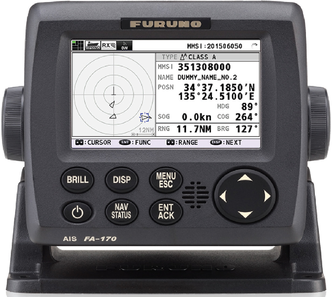
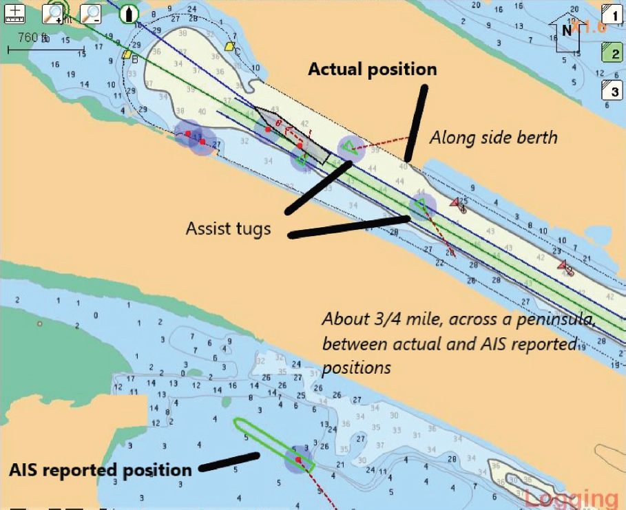
Currently, there is no mechanism to ensure the accuracy and authenticity of AIS data. Therefore, it is imperative for mariners to exercise caution when relying on the information provided due to faulty GPS units either integrated into the AIS unit or attached to the AIS in addition to the AIS units not being set up properly and inaccurate information input. Although 33 CFR 164.466 describes which vessels are required to have a properly installed, operational AIS, the applicability of this regulation is currently only within U.S. Navigable Waters as defined in 33 CFR 2.36,7 which only applies up to 12 nautical miles (nmi) offshore. Since a majority of the OREI will be developed outside 12 nmi on the U.S. OCS, use of AIS is not required on all vessels operating in the vicinity of WTGs. It is, however, feasible for the U.S. Coast Guard to pursue a regulatory change that would require AIS use out to 200 nmi. Additionally, the required minimum keyboard display is basic (Figure 3.1). The feasibility of using AIS to assist with safe navigation within an OREI would be dependent on capabilities of the AIS installed, its integration with other installed navigational equipment, and the accuracy of the information inputted into the system (Figure 3.2).
Existing AIS technology could allow OREI developers to install AIS transceivers on specified wind turbines and could assist the mariner when navigating through the wind farm. However, AIS transmitters would best be used sparingly to highlight particular WTGs important to maintain situational awareness such as the corners of a wind farm.
___________________
5 A detailed overview of AIS can be found via the U.S. Coast Guard Navigation Center (NAVCEN) website, https://www.navcen.uscg.gov/?pageName=AISmain.
6 See https://www.ecfr.gov/current/title-33/chapter-I/subchapter-P/part-164/section-164.46.
7 See https://www.ecfr.gov/current/title-33/chapter-I/subchapter-A/part-2/subpart-B/section-2.36.
Electronic Chart System and Electronic Chart Display and Information System
Similar to AIS, ECS and ECDIS are not required on all vessels. ECDIS and ECS are navigational information systems, interfaced with other navigational equipment such as the GPS, Gyro, Radio Assisted Detection and Ranging (RADAR), Automatic Radar Plotting Aid (ARPA), and Echo Sounder. ECDIS is a high-quality ECS, which meets the requirement of the International Maritime Organization (IMO) performance standard and has been tested by an independent type-approval authority. ECDIS has several advantages over paper charts for navigation. For example, all information is processed and displayed in real time, alarms and indications are available to indicate dangers, charts can be customized to meet the needs of the voyage, features can be examined more closely via zoom capabilities, charts can be interrogated for detailed information, and other navigational equipment (e.g., AIS, ARPA) can be overlayed and integrated for display (Bhattacharjee, 2021).
While ECDIS facilitates passage planning, chart correction, orientation, review of navigational information, and other activities in support of safe navigation, it also has some limitations. The accuracy of the information received via AIS or other equipment interfaced with the ECDIS is only as good as the accuracy of the information transmitted to that equipment. Some sensors providing information may lack integrity with regard to accuracy. Additionally, the position of ships received on an ECDIS display may not be referenced to the same coordinate system. It is therefore imprudent for the officer of the watch to depend solely on the information on the ECDIS—an aid to navigation that does not replace the human quotient, which brings in the skill and expertise with experience that an ECDIS cannot provide (Bhattacharjee, 2021).
New Technology
The integration of new technology onto vessels operating in and around offshore wind farms may enhance situational awareness in the event that radar systems are compromised. Infrared camera systems and Light Detection and Ranging (LiDAR) are not required to be carried, and are rarely seen on U.S. vessels, but may be useful in detecting targets missed by other means. Infrared maritime thermal camera systems are based on the principle that all objects emit thermal energy, and different objects can emit different thermal signatures. Sensors integrated into infrared detection systems can perceive and convert thermal energy emitted by an object above absolute zero into an electrical signal that can be processed to create an image.8,9 Infrared systems can therefore provide vessel operators with the ability to sense targets in the infrared part of the electromagnetic spectrum, in total darkness and through solar glare, and with performance diminished in the presence of fog and smoke. Infrared thermal vision may bring improved clarity to confusing and dangerous situations on the water. However, infrared thermal imaging on its own will not provide
___________________
8 See https://www.lynred.com/blog/infrared-technology-and-thermal-cameras-how-they-work.
any range information. LiDAR operates at a longer range due to its three-dimensional laser scanner, with the potential to provide accurate and precise real-time position information for moving and stationary objects, infrastructure, and the coastline. LiDAR’s ranging capability can provide advanced situational awareness information to ships during the day or night, with weather restrictions, and includes advanced functionalities to assist with collision avoidance. This includes the ability to discern individual ships when clustered together and to distinguish ship size, including detecting very small ships. LiDAR allows distance to obstacles on surrounding land or water to be accurately measured in real time, with reduced clutter and minimal returns off water to ensure accurate data collection under variable conditions.10 Regarding the feasibility of integrating these technologies into MVR systems, the effective range of these systems is generally much shorter than MVR, especially in adverse weather and in the presence of smoke and other aerosols, and so their use in the marine environment requires careful evaluation and integration with other systems.
Steering Clear of Wind Farms If Possible
Shipping safety fairways, traffic separation schemes, and other ships’ routing measures are being designated to ensure areas of the waterways are cordoned off to recognize the paramount right to navigation. The size, space, and location of these fairways and routing measures will be determined with input from multiple government agencies and all maritime stakeholders. By designating the appropriate space (determined by size and maneuverability of the vessel, visibility, etc.) for vessels to transit, it would be feasible for large vessels entering and exiting the major shipping ports along the Atlantic Coast of the United States to steer clear of the wind farms.
Additional Training
Credentialed mariners are required to be familiar with the proper operation of all installed navigation equipment. If this equipment is modified or replaced because of a new performance standard, training would need to be developed to assure watchstanders attain the competence to use that equipment effectively (46 CFR 15.405; STCW Regulation II in IMO, 2018). When new parameters are introduced into the operating environment, credentialing authorities and companies (STCW Regulation I-14) review training requirements to ensure that safe navigation through proper operation of required equipment can still be met.
Updating operator training to include specifics on WTGs could help mitigate navigation risks caused by WTGs. While WTG clutter on the radar display may look confusing and unmanageable at first, mariners could gain proficiency at distinguishing real targets from WTG clutter through training and practice. First-order scattering effects present a regular grid pattern on the display due to the wind farm layout and thus could be easily identified. Higher-order scattering effects are often less stable with respect to look angle and tend to be highly transitory when vessels move. Distinguishing them from real targets could be possible. During the 2007 Kentish Flats trial (Marico Marine, 2007), it was reported that experienced pilots were able to effectively track other vessels from both within and behind the wind farm area. The Maritime Institute of Technology and Graduate Studies (MITAGS) simulator facility in Baltimore, Maryland,11 has taken a step in this direction by implementing simulation capabilities to train pilots to navigate around and through specific wind farms.
While it is feasible for the mariner to receive training on proper methods to safely navigate through the wind farms using MVR, several potential bottlenecks are noted. First, the creation of new training courses is only likely if new manufacturing standards for MVR are adopted or
___________________
10 See for example, see https://www.neptectechnologies.com/marine-lidar/.
credentialing requirements changed. With projected timelines of 5–10 years for standards bodies to approve updates, and an additional 5 years for U.S. government regulators to update CFR, formal training is unlikely feasible as a short-term solution. A more promising short-term solution is to encourage mariners to develop proper navigation skills for future wind farm installations. This may be accomplished if IMO issues a Maritime Safety Committee Circular or the U.S. Coast Guard develops a Navigation and Vessel Inspection Circular to address safety concerns when navigating in the vicinity of wind farms similar to the United Kingdom’s Marine Guidance Note 372. Second, simulators are only effective if the underlying simulation models provide sufficient realism to emulate the actual phenomenology. Higher-order scattering effects leading to spurious echoes are much more challenging to model accurately. None of the existing signature modeling approaches for these effects has been validated against measurements. More realistic simulation capabilities will need to be further developed and tested for mariner training.
Enhancing the capabilities of training facilities requires an investment in representative user hardware, computing technology, and realistic interactions between the MVR and environment using simulation models. It is expected, however, that the corresponding investment is reasonable in comparison with the important benefits of offshore, renewable energy.
Wind Turbine Generator Design and Deployment
As discussed in Chapter 2 of this report, the standard design for an offshore WTG for the near term will be the three-bladed horizontal axis wind turbine. Hence, this section will focus on this WTG design.
Numerous techniques are being investigated to reduce the radar cross section (RCS) of WTG involving material choices (e.g., carbon fiber composites and radar absorbing materials [RAM]) for the WTG blades to mitigate clutter and shadowing for land-based WTG installations. The reduction of the clutter with new blade compositions will also be welcome for marine installations, though this reduction may only have noticeable effects in MVR returns in close proximity to or within the farms themselves, as a significant component of the radar return originates from reflections from the tower. The location of the blades well above the ocean surface from which the radar signals originate may make this approach less compelling as a motivating factor to improve performance of MVR.
These RCS reduction approaches have been the subject of at least three studies: “Stealth Technology for Wind Turbines,” a report prepared by BAE Systems Advanced Technology Centre with Vestas Technology U.K. Ltd. for the Department for Business, Enterprise and Regulatory Reform for the United Kingdom in 2007 (BERR, 2007); “Radar-Cross-Section Reduction of Wind Turbines (Part 1),” prepared by Sandia National Laboratories in 2012 (McDonald et al., 2012); and “Stealth Wind Farm,” a case study prepared by QinetQ in 2018 (QinetiQ Ltd., 2018).
The 2007 BAE Systems study examined the entirety of the WTG and aimed to reduce the RCS through a combination of RAM and the development of radar-friendly shape designs for the tower and nacelle. The study focused on the S-band radar frequency (2.7–3.1 gigahertz [GHz]), though the authors noted that RCS reduction in the X-band (9.1–9.41 GHz) is also desirable for MVRs. The BAE Systems study estimated that the total RCS of a WTG needed to be reduced by at least 25 decibels (dB) in order to successfully mitigate the impacts of WTGs on radar systems (BERR, 2007). BAE Systems researchers found that “the towers require the largest level of RCS reduction, of the order of 40 dB. Even so, the nacelle and blades also require up to 30 dB of RCS reduction.” In partnership with the University of Manchester, the BAE Systems team modeled the North Hoyle Offshore Wind Farm to generate a simulated plan position indicator (PPI) plot that mariners might see on their radar screens. The PPI was simulated with an initial assumed WTG RCS of 61.4 dB and then again after reducing the RCS of each WTG by 5, 10, and 20 dB. All cases, except the 20-dB
reduction, showed some sidelobe or ghosting effect from the WTGs. The study did not move past the modeling phase to manufacture and construct a reduced RCS WTG that could be tested in the field to validate the modeled results.
The Sandia National Laboratories (Sandia) study investigated the incorporation of RAM into the fabrication process of WTG blades (McDonald et al., 2012). This study focused on the L- and S-band radar frequencies. The Sandia study looked solely at the reduction of the RCS for the blades and did not investigate the tower or the nacelle. This was because, as the authors of the study noted, that while the tower and nacelle produce larger radar returns than the blades, these stationary returns can be managed by similar techniques used to filter returns from large buildings like clutter maps. This is not the case for non-stationary MVRs.
Sandia National Laboratories developed a WTG blade design with integrated thin layers of RAM included in the blade structure (McDonald et al., 2012). Results from the Sandia study indicate that the integration of RAM in a WTG blade manufacturing process is feasible, and the modeling has shown that it can achieve 20 dB or greater RCS reduction at certain frequencies (McDonald et al., 2012). However, more research and development activities are needed to validate the modeling and understand the applicability to MVRs specifically.
A case study report released by QinetiQ in 2018 indicates that QinetiQ, partnered with the wind farm developer EDF, was able to reduce the RCS of a 35-WTG wind farm in France by 20 dB, as seen by a nearby weather radar using RAM (QinetiQ Ltd., 2018). No other information was available regarding the techniques used to achieve this reduction nor the applicability to MVRs.
Other approaches to reduce the overall RCS of WTGs involve altering the surfaces of the towers in order to provide a less persistent return to the illuminating radar, including coating with RAM or addition of faceted or “bumpy” surface treatments to the tower surface (e.g., Ueng, 2020). These kinds of approaches will likely be able to reduce the RCS of individual WTG towers in a farm but may result in additional clutter within the confines of and adjacent to the farm. Additionally, any non-smooth surface will present additional wind loading and opportunities for debris deposition on the surface, which could shorten the overall mechanical strength and useful lifetime of the tower.
The BAE Systems and Sandia studies have both shown that the reduction of RCS for WTGs is feasible (BERR, 2007; McDonald et al., 2012). However, a completely undetectable WTG is undesirable in the marine environment. In addition, questions remain about the applicability of these techniques to MVRs, which will require additional research and development. Lastly, the committee notes that floating offshore wind farms may pose additional challenges in the interpretation of their marine radar returns due to wave-related motions of individual WTGs.
Radar Design, Signal, and Data Processing
To date, compelling WTG mitigation techniques for MVR have not been substantially investigated, developed, matured, or deployed. This is in contrast to U.S. Department of Defense and Federal Aviation Administration radar systems, where significantly higher investment has been made in characterizing impacts and actively developing solutions.12 In this section, possible mitigation measures in MVR deployment and MVR design are discussed.
Marine Vessel Radar Deployment
As explained in Chapter 2, a large offshore wind farm presents a large cluster of radar reflecting objects to MVRs. This can result in (1) first-order scattering effects leading to clutter and shadow issues, thus making it more difficult to detect targets in and around a wind farm; and (2)
___________________
12 See https://windexchange.energy.gov/projects/radar-interference-working-group.
higher-order scattering effects (multipath from the observer’s own vessel, other vessels, between turbines) leading to spurious echoes and compounding WTG interference on MVR. The radar phenomena observed are not unique to WTGs but are exacerbated by their large RCS. Therefore, traditional approaches to dealing with clutter returns from large RCS objects can be considered. These methods include enhancing the RCS of small vessels that are difficult to detect and reducing own vessel scattering. These techniques apply to both magnetron-based and solid-state MVRs.
Radar Reflectors
To improve detection in the presence of large WTG clutter, one approach is to install radar reflectors on small vessels to increase their RCS. It was found during the U.K. trials that experienced pilots were able to use various radar controls (gain, sensitivity time control, pulse width) to detect small targets around wind farms, as long as target RCS was above established navigation buoys (Brown and Howard, 2004; Marico Marine, 2007). Therefore, boosting the RCS level of small vessels to above that of nearby buoys is a way to ensure they can be seen by MVRs on other vessels when navigating around a wind farm. In fact, Safety of Life at Sea (Chap. V, Reg. 19.2.1.7) already requires that all ships, if less than 150 gross tonnage and if practicable, have a radar reflector to enable detection from ships navigating by radar at both 9 GHz and 3 GHz. Corner reflectors, lenses, or active reflectors are commercially available for this purpose (Hodges, 2005). When mounted high on the vessel, they can boost the RCS level to several square meters for passive reflectors or lenses, and to more than 100 square meters for active reflectors. Although it was found that the RCS of these products might not be satisfactory for all look angles, they are a rather low-cost solution to enhance the detectability of small vessels by other MVRs. Passive reflectors are preferable over active reflectors, as they are easy to maintain and do not lead to spectrum management requirements as in the active reflector case.
Marine Vessel Radar Placement
Cutting down platform scattering can reduce spurious echoes arising from multiple scattering. This can be accomplished through better MVR placement on the vessel and/or RAM treatment of surrounding structures such as masts, funnels, stacks, or derricks. It was found during the Kentish Flats trial (Marico Marine, 2007) that a large fraction of spurious echoes observed on PPI displays were traceable to own vessel obstructions. In particular, cylindrical shaped masts, stanchions, or funnels gave rise to spurious sectored echoes in the direction of the obstructions at the same range as the WTGs. Flat surfaces sometimes gave focused ghost images of the entire farm in the direction of these surfaces. If a vessel operates adjacent to or inside a wind farm, careful calibration and testing of its MVR could eliminate (or at least clearly identify) shadow or blind sectors due to onboard obstructions. Clearly labeling these sectors on the MVR will serve as a reminder to the pilot that artifacts in these directions are more likely, especially when navigating adjacent to or inside a wind farm. Use of RAM or coatings to treat the offending surfaces may also help reduce multiple scattering between large WTGs and these surfaces. Absorber sheets made of magnetically loaded rubber or silicone that are thin and flexible have been used on naval ships for this purpose (Cuming Microwave, 2015; TDK, 2021). They could provide an off-the-shelf solution to reduce spurious echoes due to platform structures.
In summary, attention to radar mounting and interaction with the MVR-carrying vessel is an important consideration. The approach taken will vary by vessel type and configuration, thereby requiring a level of customization. Identifying and treating reflective points on the vessel to reduce their impact on the MVR will yield substantial benefit. A downside is that the treatments will generally require regular maintenance.
Marine Vessel Radar Design
The majority of MVRs in operation today use magnetron technology. Solid-state radar is a relatively new technology. While gaining popularity, it still only currently occupies a small fraction of the installed base. Furthermore, the susceptibility or immunity of solid-state radar to WTG interference has not been established via rigorous in-situ testing. Earlier MVR measurement collections on WTG interference (Brown and Howard, 2004; Marico Marine, 2007) were done using magnetron-based radar exclusively. Therefore, assertions of the suitability of solid-state radar, or lack thereof, for operation in a WTG environment are inconclusive from these experiments. Nevertheless, solid-state radar offers a greater potential in overcoming WTG interference than magnetron radar. This is because solid-state radar is fully coherent and can detect Doppler information, which opens up an additional dimension for separating moving targets from WTG clutter. Below, the radar signal processing steps and the corresponding radar features from targets and clutter sources are discussed.
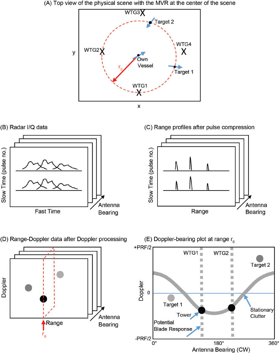
We now consider how coherent signal processing can be used as an advantage to filter unwanted WTG returns building on the prior discussion. Figure 3.3(A) illustrates a typical scene with four WTGs and two targets in the field of view of an MVR, which is located at the center of the scene. Figure 3.3(B) shows the raw radar I/Q data collected over fast time, slow time (or pulse number), and antenna bearing angle. In the first processing step, range compression is applied to the radar I/Q data along the fast time axis and results in a set of range profiles versus slow time and antenna bearing, as shown in Figure 3.3(C). In the second step, a fast Fourier transform is applied along the slow time axis to generate a range-Doppler plot for different antenna bearing angles, as shown in Figure 3.3(D). Figure 3.3(E) shows the resulting Doppler versus bearing plot at a particular range cell, r0. Due to the finite pulse repetition frequency (PRF) of the radar, the maximum extent in the Doppler dimension is limited by ±PRF/2. For this discussion, the antenna bearing angle is defined in a clockwise manner, starting from the front of the vessel. In the plot, returns from stationary objects (including land mass and towers of the WTGs) are mapped to a sinusoidal trajectory in the Doppler-bearing plane. The maximum Doppler of the sinusoid is proportional to the speed of the own vessel. Moving targets (e.g., Targets 1 and 2) are offset from this curve. WTG blade returns could also be present when the antenna is pointed in directions of the WTGs and are marked by dashed lines. They are spread out in Doppler because of the various Doppler components produced along the blade from the hub to the tip. From Figure 3.3(E), it can be seen that moving targets, stationary clutters (including both land and WTG towers), and dynamic clutters (due to WTG blade returns) all have rather distinct behaviors in the Doppler-bearing space. This makes it possible to devise an automated algorithm to filter out clutter and detect moving targets. To do so for a magnetron-based radar would be akin to trying to detect targets in clutter with the entire Doppler dimension collapsed to a line.
Several comments are in order:
- The successful detection of targets from clutter depends on their separation in range, Doppler, and azimuth bearing. Therefore, such processing is still subject to the usual resolution limit and sidelobe leakage in the range, Doppler, and antenna beam dimensions. Improved resolution via shorter effective pulse length, longer dwell time, or narrower antenna beam will lead to improved target detection.
- Spurious echoes emanating from own vessel, other vessels, or between turbines will not be mitigated by using Doppler filtering. For example, spurious echoes due to multiple scattering between a shipboard obstruction and a WTG tower will not obey the assumed sinusoidal trajectory in the Doppler-bearing plot for stationary clutter. They will still interfere with moving target detection.
- The PRF of MVRs may be too low to capture the Doppler return from WTG blades without ambiguity. For example, the U.S. Department of Energy anticipates that the maximum tip speed of offshore WTG blades in the next 15 years will be in the range of 100 meters per second (Ennis, 2021). This corresponds to a maximum Doppler shift of 6.3 kilohertz at 9.4 GHz, which is above the typical PRF of MVRs. Consequently, the blade return may fold back into the Doppler extent dictated by the PRF. On the other hand, as discussed in Chapter 2, the blade return is prominent only when the blade is perpendicular to the radar line of sight. Therefore, the Doppler flash may not always be captured during the antenna dwell on the WTG. Even if it is present, the return is spread over multiple Doppler bins and is much weaker than the coherent return from the entire blade.
- The WTG interference problem for MVRs is less difficult than what has confounded air traffic control and air defense radars. That is because all targets of interest are confined to the sea surface and the problem is essentially a two-dimensional one. This is in contrast to the case of air traffic control and air defense radars that have to detect and track targets in a three-dimensional space, thus making it very difficult to track aircraft flying over a wind farm (Karlson et al., 2014).
- The ARPA takes radar measurements (detected objects at specific ranges and angles) and assembles them into tracks and predictions on approach points. Trackers rely on logic to initiate tracks, assign measurements to tracks, drop tracks, and determine track priority. As noted in Chapter 2, the many spurious measurements emanating from a WTG degrade ARPA performance. Developing, testing, and enhancing an ARPA mode for WTG operation is a data processing–centric approach to mitigate WTG effects and improve performance for the operator. For example, the tracker can incorporate knowledge of WTG locations to remove the resulting tower measurements and blade Doppler from further tracker consideration.
- Other filtering methods based on signal decomposition, model-based signal processing, and iterative deconvolution used in other radar systems may also be possible. The essential concepts are similar to Doppler filtering and involve suppressing those signal components that differ from targets of interest.
- The elevation beamwidth of currently fielded MVRs exacerbates ambiguous signals. As mentioned, the wide elevation beamwidth accommodates vessel pitch and roll. It is possible to deploy antennas with narrower elevation beamwidth and the ability to switch beam positions based on vessel motion. Such deployments will require greater antenna area (along the vertical dimension) to reduce the elevation beamwidth, as well as inertial navigation measurements and electronics to switch elevation beam pointing appropriately. Antenna improvements can be made to both solid-state and magnetron-based radar, but consistent with our current discussion, application to solid-state radar will yield the most flexibility for system improvement in a WTG environment.
- As solid-state radar supports a range of duty cycles, flexibility in waveform parameter selection is feasible. Incorporating available arbitrary waveform generator technology in future solid-state MVR designs enables waveform parameter optimization, thereby providing another degree of freedom that may prove useful in minimizing WTG interference. For example, the arbitrary waveform generator supports emerging techniques, such as phase tagged waveforms capable of separating range ambiguous clutter returns, an approach which may help suppress WTG returns from far ranges.
In summary, the committee finds that it is within the “realm of the possible” to leverage solid-state radar technology and apply coherent signal processing to filter out both static and dynamic WTG clutter signals and detect moving targets. Since this type of processing can be carried out in
software, it may not require hardware changes to existing solid-state radar. In fact, it is conceivable that a “wind farm” mode can be created on future MVRs to suppress/filter WTG clutter automatically. Additionally, ARPA upgrades for a WTG mode primarily require software modifications; incorporating inputs from external sources, such as AIS, may require additional system modifications, though such information is likely available in modern, integrated navigation consoles. Software updates may require computer hardware updates; moreover, software updates require some degree of verification and validation before fielding. Finally, improved antenna technology is feasible, and may leverage current trends in the commercial sector, but certainly will add to the cost and complexity of the MVR.
Given the aforementioned discussion, the committee emphasizes that the susceptibility of the current generation of solid-state radars to WTG interference is unclear. This is the case largely because MVR manufacturers have leveraged solid-state technology mostly as a like-for-like replacement to the magnetron to improve reliability, with some added features not specifically addressing WTG interference. Extensive testing against future U.S. offshore wind facilities at the earliest possible stage would shed light on their impacts to solid-state radar.
Lastly, cost is a dominant consideration in the design and manufacture of MVRs, especially for the commercial market. Manufacturers may be unwilling to consider modifications to their current designs that can substantially improve MVR performance in the presence of WTGs unless required to do so by new regulations.
Other Information Systems and Combined Methods
Radar navigational issues arising from the presence of WTGs will mainly be relevant in close proximity to or within WTG farms. The possibility of smaller vessels passing through the WTG farms and having their signatures masked by the close-in radar returns or shadowing from the WTGs and their clutter can make detecting small disabled vessels and vessels in distress a challenge. Shutting down WTG blade rotation during search and rescue (SAR) operations may provide some benefit, though strong returns from the tower and stationary blades remain a limiting factor. The feasibility of installing dedicated in-farm radars to provide situational awareness in and around WTG farms will be based on cost and system maintenance requirements. The installation would require dedicated connections to a Coast Guard watch station or the local substation. The radar and signal processing technologies already exist to enable such a system. The industry ecosystem in this space may readily support its design and development, given the increased deployment of marine wind farms over the coming decades that could create a market for such a system. This kind of technology may be even more important in floating WTG farms, where RCS clutter and variability will depend more heavily on sea state.
However, apart from the specialized application of prospective SAR operations, the case for in-farm radars and related systems is less compelling. While these systems could be fielded, it is much less straightforward to consider how these resources would be used to supplement shipboard MVR given that there is no established way to send such data to any vessel at sea. This situation may shift once wind farms of significant size are deployed, and the Coast Guard and other organizations have more data with regard to the need for real-time situational awareness in marine wind farms in general for SAR operations as well as routine navigation.
REFERENCES
BERR (U.K. Department for Business, Enterprise and Regulatory Reform). 2007. Stealth Technology for Wind Turbines, Final Report, Contract Number W/44/00658/00/00, URN Number 08/747, MTSM/070348/109121 TES 101865, Issue 1. http://users.ece.utexas.edu/~ling/EU4%20BAE%20Stealth%20Technology%20for%20Wind%20Turbines.pdf.
Bhattacharjee, S. 2021. What Is Electronic Chart Display and Information System (ECDIS)? (In Marine Navigation). Marine Insight, August 31. https://www.marineinsight.com/marine-navigation/what-is-electronic-chart-display-and-information-system-ecdis/.
Brown, C., and M. Howard. 2004. Results of the Electromagnetic Investigations and Assessments of Marine Radar, Communications and Positioning Systems Undertaken at the North Hoyle Wind Farm by QinetiQ and the Maritime and Coastguard Agency. MCA Report MNA 53/10/366 or QINETIQ/03/00297/1.1. United Kingdom Maritime and Coastguard Agency. www.mgca.gov.uk.
Cuming Microwave. 2015. C-RAM FLX Thin, Flexible, Weatherproof Microwave Absorber. Technical Bulletin 310-1. https://www.cumingmicrowave.com/rubber-sheet-absorbers/flexible-tuned-frequency-magnetic-sheet-absorber.html.
Detweiler, G. 2021. Lecture: Navigation and Safety Using Marine Vessel Radar: Overview of Marine Navigation and Safety Considerations Regarding the Use of Marine Vessel Radar in the Presence of WTGs. Presentation to the Committee on Wind Turbine Generator Impacts to Marine Vessel Radar, September 16, 2021. https://www.nationalacademies.org/event/09-16-2021/wind-turbine-generator-impacts-to-marine-vessel-radar-meeting-3.
Ennis, B. 2021. Lecture: Offshore WTG Characteristics and Deployment (Sandia National Laboratories). Presentation to the Committee on Wind Turbine Generator Impacts to Marine Vessel Radar, September 16, 2021. https://www.nationalacademies.org/event/09-16-2021/wind-turbine-generator-impacts-to-marine-vessel-radar-meeting-3.
Hodges, T. 2005. Can you see me––on test radar reflectors. Yachting Monthly, June.
IMO (International Maritime Organization). 2018. Standards of Training, Certification, & Watchkeeping for Seafarers (STCW) including 2010 Manila Amendments. IMO PUB-IMO-STCW-2017.
Karlson, B., B. LeBlanc, D. Minster, D. Estill, B. Miller, F. Busse, C. Keck, J. Sullivan, D. Brigada, L. Parker, R. Younger, and J. Biddle. 2014. Wind Turbine-Radar Interference Test Summary. Sandia Report: IFT&E Industry Report. Sandia National Laboratories. U.S. Department of Energy. https://www.energy.gov/sites/prod/files/2014/10/f18/IFTE%20Industry%20Report_FINAL.pdf.
Marico Marine. 2007. Investigation of Technical and Operational Effects on Marine Radar Close to Kentish Flats Offshore Wind Farm Kentish Flats. BWEA (British Wind Energy Association) Technical Report, CCE5 No.1. London, UK: Department for Transport.
McDonald, J.J., B.C. Brock, S.E. Allen, P.G. Clem, J.A. Paquette, W.E. Patitz, W.K. Miller, D.A. Calkins, and H. Loui. 2012. Radar-Cross-Section Reduction of Wind Turbines (Part 1). Sandia Report: SAND2012-0480. Sandia National Laboratories. U.S. Department of Energy. https://doi.org/10.2172/1038185.
QinetiQ Ltd. 2018. Case Study: Stealth Wind Farm. QINETIQ/18/01407. https://www.qinetiq.com/en/blogs/Stealth-Wind-Farm-Case-Study.
Salerno, J., A. Krieger, M. Smead, and L. Veas. 2019. Supporting National Environmental Policy Act (NEPA) Documentation for Offshore Wind Energy Development Related to Navigation. OCS Study BOEM 2019-011:1–89. Washington, DC: U.S. Department of the Interior, Bureau of Ocean Energy Management.
TDK. 2021. Radio Wave Absorbers for EMC Anechoic Chambers/for Microwave Anechoic Chambers IP-BLB/IP/IP-BX/ITF/ICM/IB/IS/IS-SM/IS-V Series. TDK-RF Solutions. https://www.tdkrfsolutions.tdk.com/images/uploads/brochures/TDK_RF_Absorber_Brochure-032021.pdf.
Ueng, S. 2020. A hybrid RCS reduction method for wind turbines. Energies 13: 5078. doi:10.3390/en13195078.


