
2 THE FREE ELECTRON LASER
HISTORICAL PERSPECTIVE
The first sources of powerful coherent radiation were the microwave tubes invented earlier in this century. Their development received a strong impetus from radar development during World War II. These tubes are still successful and useful sources of coherent radiation with wavelengths ranging from several meters to about 1 millimeter. Microwave tubes operating at kilowatt power levels are found in nearly every home, and radar and communications applications also affect our daily lives.
The concept that a resonant cavity should be about the same size as the stored wavelength limited the microwave tube to wavelengths greater than about 1 mm. The invention of the open resonator (Schawlow and Townes, 1958) led to the development of the conventional laser and an immediate reduction in the attainable wavelength by about four orders of magnitude. The optical resonator with macroscopic dimensions that could store significant optical power at short wavelengths was crucial to the invention of the laser.
The free electron laser (FEL) is a natural alternative as a radiation source (National Research Council, 1982). In 1971, J.M.J. Madey invented and developed the FEL, a relativistic electron tube that made use of the open optical resonator. An important step in FEL development came in 1976 when Madey and his co-workers at Stanford University measured gain from an FEL configured as an amplifier at 10-µm wavelength. This experiment, and the successful operation of the same FEL configured as an oscillator in 1977 at 3-µm wavelength, created a large interest in FEL research. Two important FEL attributes, tunability and design flexibility, were demonstrated by these two experiments at significantly different wavelengths using the same apparatus.
PRINCIPLES OF OPERATION
In an FEL a beam of relativistic electrons produced by an electron accelerator passes through a transverse, periodic magnetic field produced by a magnet called an undulator and exchanges energy with an electromagnetic radiation field. Efficient energy exchange requires that the electrons experience nearly resonant forces from the radiation and undulator fields. This resonance is achieved when the radiation wavelength λ, the electron-beam axial velocity cβz, and the undulator period λ0 satisfy λ ≈ λ0(λ − βz), where c is the speed of light. The resonance relationship shows that the FEL can be continuously tuned by changing the electron-beam kinetic energy (γ − 1)mc2, where γ = (λ− β⊥2 − βz2)−½ is the relativistic Lorentz factor, m is the
electron mass, and cβ⊥ is the transverse electron velocity. It also indicates that the FEL mechanism can be designed to operate over a large range of wavelengths, from centimeters to nanometers. The actual feasibility of operating in a given wavelength range depends on several factors, including the FEL gain and electron-beam quality.
Figure 7 is a schematic of an FEL, with the periodic undulator field indicated by the alternating up and down arrows. The typical peak magnetic field in the undulator is a few kilogauss with a wavelength of λ 0 ≈ several centimeters over N ≈ 100 periods. The length of the undulator is several meters inside the optical resonator mirrors, which are separated by about twice the undulator length, or about 10 meters. The electron-beam path is indicated horizontally. The beam energy can vary from a few MeV to several GeV, although the typical FEL uses an electron-beam energy of around 50 MeV. The transverse dimensions in the FEL schematic are exaggerated with respect to the longitudinal distance shown. The electron-beam radius is typically about 1 mm, and the optical mode waist is about 3 mm. The electron-beam pulse width can be as long as several microseconds for a recirculating electrostatic accelerator. In a radio frequency (RF) accelerator or storage ring, the electron-beam structure is determined by the RF frequency. In an RF accelerator, only those electrons with the correct phase relation in the RF cycle continue to be accelerated. The resulting accelerated electron current is produced in short micropulses of a few picoseconds. The minimum separation between micropulses is one RF cycle, but often there is a much larger separation of many nanoseconds. The stream of micropulses continues for about 10 µs up to about 1 ms because the RF power source is pulsed. This stream of micropulses is called a macropulse. In a storage ring using lower-frequency RF, the micropulse length is typically a nanosecond in length separated by several RF cycles. There is no macropulse in a storage ring. The radiation pulse structure in an FEL reflects that of the electron beam.
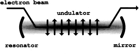
FIGURE 7 Schematic of a free electron laser.
The requirements of high electron-beam current and quality are crucial in determining the ultimate performance of an FEL. The electron-beam kinetic energy (γ− 1)mc2 can range from a few MeV to several GeV, while the beam current can range from a few amperes to several kiloamperes. The FEL is able to obtain large peak power, on the order of a few gigawatts, because, unlike conventional lasers or microwave tubes, the energy that is not transferred to the radiation field remains in the relativistic electron beam that is transported out of the undulator at nearly the speed of light, or even recovered to improve overall efficiency. The FEL interaction volume contains only light, the undulator magnetic field, and the electron beam, so that unwanted high field effects and thermal distortion of the medium are absent in the FEL. The small duty cycle of most accelerators limits the average power of FELs. The efficiency of FELs has been demonstrated to be greater than 40% at long wavelengths, but most will operate at a lower efficiency of a few percent.
The classical gain in the low-gain FEL oscillator develops from coherent electron bunching on the scale of the radiation wavelength. As the electrons travel through the undulator, they accelerate from side to side and spontaneously radiate in the forward direction. The spontaneous emission process is the same as is used to generate UV and x-rays in the undulators and wigglers of synchrotron radiation sources. On the first few passes through the FEL oscillator, some of this spontaneous radiation is stored in the resonator. As the radiation power grows over many passes, the emission process begins to differ from that of the synchrotron sources and becomes similar to the mechanism used in the early microwave electron tubes.
The electrons entering the operating FEL are forced to move from side to side due to the undulator magnetic field, but now radiate in the presence of the stored transverse radiation field. As the radiation passes over the more slowly moving electrons, the radiation electric field does work on the oscillating electrons. This is the classical analog of quantum stimulated emission. A significant energy exchange can occur only when the undulator and radiation field forces on the relativistic electrons are nearly resonant. The electrons in the beam are initially randomly spread over many radiation wavelengths with many millions of electrons within each section of the beam one wavelength long. The orientation of the radiation's electric field vector and the electron's undulator velocity vector rotates through 2π within each radiation wavelength. These different orientations determine that about half the electrons lose energy to the radiation field, while other electrons gain energy from the co-moving wave. The electrons that gain energy begin to move ahead of the average electron, while the electrons that lose energy begin to fall behind the average. As the faster electrons move ahead of the average and the slower electrons move back, the beam is periodically bunched on the radiation wavelength scale. Since the electron energy loss and gain repeats throughout the electron beam over many radiation wavelengths, the beam becomes bunched on the scale of the radiation wavelength. The emission rate for a perfectly bunched beam of electrons is proportional to the square of the number of electrons, whereas the emission rate for a beam of randomly positioned electrons is only proportional to the number of electrons. The same kind of electron bunching is the goal of the microwave electron tube design. The FEL works in a
similar way, but can reach infrared, optical, UV, or even x-ray wavelengths. The bunched beam then radiates coherently and amplifies the existing radiation.
There is always an energy spread imposed on the electron beam in order to move the electrons together in a bunch. When the beam has an initial energy, or velocity spread, the bunching process can be impaired, reducing gain. In the FEL oscillator working in steady state at high power, the electrons become over-bunched at the end of the undulator and actually take energy back from the radiation field. This is the normal saturation process, and typically limits the fraction of the electron-beam power converted to radiation in a single pass to 1/N.
In an FEL amplifier (as opposed to an oscillator), the high current of the electron beam increases the rate of the electron bunching process along the undulator. For sufficiently high beam current entering a sufficiently long undulator, the same electron bunching process that occurs over many passes in the FEL oscillator can be completed in a single pass along the FEL amplifier. The amplified wavelength can be selected by an external oscillator laser. In the superradiant FEL, there is no external oscillator, so that radiation must first grow from spontaneous emission. As the optical power grows, the spectrum narrows to establish coherence. This process is called self-amplified spontaneous emission (SASE).
The relativistic electrons “see” each rapidly advancing undulator period Lorentz contracted to a shorter wavelength, λ0′ = λ0/γ. Also, the electrons “see” the radiation field passing over them as Doppler shifted to longer wavelengths, λ′ = (1 + βz) γλ ≈ 2 γλ. The condition of resonance between the undulator and radiation forces in the beam frame, λ0′ = λ′, gives the FEL resonance condition in the laboratory frame, λ = λ0/2 γ2.
Two interesting reviews of free electron lasers can be found in Brau (1988) and Pellegrini (1994).
PROPERTIES
Many of the properties of the FEL can be inferred from the above discussion. These properties are summarized below.
-
Tunability. Because the FEL uses a single gain medium, the relativistic electron beam, and because the resonant condition can be easily tuned by changing either the electron beam energy or the magnetic field strength, FELs are broadly and easily tuned. A factor-of-10 tunable frequency range has already been demonstrated with the same accelerator and undulator.
-
High peak power. Because waste energy is carried away at nearly the speed of light and because the lasing medium cannot be damaged by high optical fields, FELs can produce very high peak powers. Gigawatt peak powers have been demonstrated.
-
Flexible pulse structure. Because the pulse structure of the radiation follows the pulse structure of the electron beam, the mature RF technology of linear
-
accelerators can be used to manipulate and control the FEL pulse structure. Picosecond pulses with sub-picosecond jitter can be produced, the interval between pulses can be varied, and there is the possibility of producing complicated pulse structures.
-
Good laser characteristics. FELs easily achieve desirable properties associated with conventional lasers, such as a single transverse mode, high spatial and temporal coherence, and flexible polarization properties.
-
Broad wavelength coverage. Because the gain medium is transparent at all wavelengths, FELs in principle can produce radiation at any wavelength. In practice, electron-beam energy, current, emittance, and energy spread requirements become more stringent as the wavelength decreases, and the cost, size, and complexity of the FEL are therefore higher at shorter wavelengths. FELs can have significant emission at harmonics of the fundamental frequency given by the resonance condition, and harmonics can be used to extend operation to shorter wavelengths than would be practical using only the fundamental frequency. At present, the shortest wavelength that has been achieved in an FEL is 240 nm, and significant use of FELs for scientific research has been restricted to the infrared. There are proposals to build vacuum ultraviolet and x-ray FELs.
-
Size and cost. Because it requires an electron accelerator with its associated shielding, the FEL has not been a device that can be placed in an individual investigator's laboratory and be operated and maintained by graduate students whose primary expertise is in other areas of science. FELs have been used principally in central facilities, where their utilization in scientific research involves associated costs of maintaining and operating the facility in addition to the cost of the device itself. FELs have been used by one user, or at most a few users, at any one time, while synchrotrons can be used simultaneously by many users. For example, the APS now under construction at Argonne National Laboratory can have 34 insertion device beamlines and 35 bending magnet beamlines, all of which can be used independently by different users at the same time. The basic science of electron accelerators is well known, but virtually all the effort spent on accelerator physics has been to reach higher energies with bigger and more costly machines. Relatively little effort has been devoted to producing the smaller and less expensive machines that would be most useful for an FEL.
EXISTING AND PLANNED FREE ELECTRON LASERS
Table 1 summarizes currently operating and proposed free electronlasers worldwide. The FEL and identified in the first column followed by a typical wavelength (λ) the electron micropulse length (σz), the electron-beam energy (E), the peak current (I),the number of undulator periods (N), the undulator wavelength (λ0),and the undulator parameter (K). The undulator parameter is K=eBλ0/2π mc 2, where B is the root-mean square undulator field strength, e is the electron charge magnitude, m is the electron mass ,and c is the speed of light. The
resonant optical wavelength can be estimated using λ=λ0(1+K2)/2γ2, where γ is the reativistic Lorentz factor and E=γmc2.The electron micropulse length is σz and in most cases is close to the optical pulse length. However, the opticalpulse can nbe up to five time longer than the electron micropulse,dependent on the adjustment of mirror position. The optical peak power can be estimated by P=IE/eN.
There are 41 existing or proposed FELs worldwide, with 22 in the United States, 8 in Japan, 3 in Russia, 2 in Germany, 3 in France, 1 in Holland, 1 in Italy, and 1 in China. Of these FELs, 21 are operating now, and the rest are proposed or under development.
REFERENCES
Brau, C.A. 1988. Science 239:1115.
National Research Council. 1982. The Free Electron Laser. National Academy Press: Washington, D.C.
Pellegrini, C. 1994. Encyclopedia of Applied Physics 8:353.
Schawlow, A.L., and C.H. Townes. 1958. Phys. Rev. 112:1940.
TABLE 1 Free Electron Lasers, 1994
|
FEL and Location |
λ (µm) |
σz |
E (MeV) |
I (A) |
N |
λ0 (cm) |
K |
Accelerator, |
|
OPERATING FELS: |
||||||||
|
UCSB(mm FEL) |
338 |
25µs |
6 |
2 |
42 |
7.1 |
0.71 |
EA,O[1] |
|
UCSB(FIR FEL) |
63 |
25µs |
6 |
2 |
150 |
2.0 |
0.13 |
EA,O[1] |
|
Tokyo(UT-FEL) |
43 |
10ps |
13 |
22 |
40 |
4 |
0.7 |
RF,O[2] |
|
Netherlands(FELIX) |
40 |
5ps |
25 |
50 |
38 |
6.5 |
1.5 |
RF,O[3] |
|
Osaka (ISIR) |
39 |
30ps |
19 |
50 |
30 |
6 |
1 |
RF,SE,O[24] |
|
Bruyeres(ELSA) |
20 |
50ps |
18 |
50 |
30 |
3.2 |
0.8 |
RF,O[4] |
|
Frascati(LISA) |
15 |
7ps |
25 |
5 |
50 |
4.4 |
1 |
RF,O[5] |
|
Grumman/(CIRFEL) |
14 |
5ps |
14 |
150 |
73 |
1.36 |
0.2 |
RF,O[23] |
|
Beijing(IHEP) |
10 |
4ps |
30 |
14 |
50 |
3 |
1 |
RF,O[6] |
|
Orsay(CLIO) |
8 |
3ps |
50 |
80 |
48 |
4 |
1 |
RF,O[7] |
|
LANL(AFEL) |
4.5 |
10ps |
16 |
180 |
24 |
1 |
0.27 |
RF,O[8] |
|
Darmstadt(IR-FEL) |
5 |
2ps |
40 |
2.7 |
80 |
3.2 |
1 |
RF,O[9] |
|
Stanford(SCAFEL) |
4 |
2ps |
43 |
4 |
120 |
3.56 |
0.9 |
RF,O[10] |
|
Vanderbilt(FELI) |
3 |
3ps |
43 |
20 |
47 |
2.3 |
1 |
RF,O[11] |
|
Duke(MarkIII) |
3 |
3ps |
44 |
20 |
47 |
2.3 |
1 |
RF,O[12] |
|
BNL(ATF) |
0.5 |
10ps |
50 |
100 |
68 |
0.88 |
0.35 |
RF,O[36] |
|
LANL(APEX) |
0.37 |
10ps |
46 |
135 |
73 |
1.36 |
0.58 |
RF,O[13] |
|
Tsukuba(NIJI-4) |
.35 |
160ps |
300 |
5 |
2×42 |
7.2 |
2 |
SR,K[14] |
|
Orsay(Super-ACO) |
0.35 |
26ps |
800 |
5 |
10 |
13 |
4 |
SR,K,O[15] |
|
Okazaki(UVSOR) |
0.3 |
126ps |
500 |
5 |
16 |
11 |
2 |
SR,K,O[16] |
|
Novosibirsk(VEPP) |
0.24 |
35ps |
350 |
6 |
2×33 |
10 |
1.6 |
SR,K[17] |
|
PROPOSED FELS: |
||||||||
|
Florida(CROEL) |
500 |
CW |
1.7 |
0.2 |
156 |
0.8 |
1.2 |
EA,O[18] |
|
Rutgers(FEL) |
140 |
25ps |
38 |
1.4 |
50 |
20 |
1 |
Mc,O[19] |
|
Osaka(ILT) |
100 |
2ps |
6 |
100 |
50 |
2 |
0.17 |
RF,O[20] |
|
Moscow(Lebedev) |
100 |
20ps |
30 |
0.25 |
35 |
3.2 |
0.75 |
Mc,O[21] |
|
Tokai(SCARLET) |
40 |
4ns |
15 |
10 |
62 |
3.3 |
1 |
RF,O[20] |
|
LBL(IRFEL) |
30 |
33ps |
55 |
60 |
40 |
5 |
1 |
RF,O[22] |
|
CEBAF(IRFEL) |
17 |
2ps |
50 |
100 |
25 |
6 |
2.1 |
RF,O[25] |
|
Novosibirsk(RTM) |
7 |
50ps |
51 |
100 |
4×40 |
9 |
1 |
RF,O[26] |
|
Boeing(APLE) |
10 |
60ps |
17 |
140 |
101 |
2.4 |
0.2 |
RF,O[27] |
|
Boeing(APLE) |
10 |
18ps |
34 |
450 |
257 |
3.9 |
1.2 |
RF,A[27] |
|
Stanford(FEL) |
10 |
4ps |
24 |
25 |
52 |
2.6 |
0.87 |
RF,O[28] |
|
UCLA(IR-FEL) |
10 |
2ps |
20 |
150 |
40 |
1.5 |
1 |
RF,A[35] |
|
Stanford(FIREFLY) |
4 |
2ps |
43 |
40 |
120 |
3.56 |
0.9 |
RF,O[29] |
|
Osaka(FELI) |
1 |
2ps |
170 |
100 |
50 |
6 |
1.26 |
RF,O[20] |
|
Dortmund(FEL) |
0.4 |
50ps |
500 |
90 |
17 |
25 |
2.1 |
SR,O[30] |
|
Harima(HIT) |
0.28 |
100ps |
500 |
3 |
170 |
1.8 |
4.2 |
SR,O[20] |
|
CEBAF(UVFEL) |
0.15 |
0.4ps |
200 |
200 |
48 |
3 |
1.5 |
RF,O[31] |
|
BNL(DUVFEL) |
0.1 |
0.2ps |
310 |
300 |
682 |
2.2 |
1.54 |
RF,O[32] |
|
Duke(Ring) |
0.05 |
10ps |
1000 |
350 |
2×33 |
10 |
1.7 |
SR,K[33] |
|
SLAC(LCLS) |
0.0004 |
0.1ps |
7000 |
2500 |
723 |
8.3 |
4.4 |
RF,A[34] |
aAbbreviations for accelerator and type:
A - FEL Amplifier
EA - Electrostatic Accelerator
K - Klystron Undulator FEL
Mc - Microtron Accelerator
O - FEL Oscillator
RF - RF Linac Accelerator
SE - Spontaneous Emission
SR - Electron Storage Ring
bReferences:
-
G. Ramian, Nuclear Instruments and Methods in Physics Research A318, 225-229 (1992).
-
E. Nishimura et al., Nuclear Instruments and Methods in Physics Research A341, 39 (1994).
-
D.A. Jaroszynski et al., Nuclear Instruments and Methods in Physics Research A331, 52 (1993).
-
P. Guimbal et al., Nuclear Instruments and Methods in Physics Research A341, 43 (1994).
-
M. Castellano et al., Nuclear Instruments and Methods in Physics Research A304, 204 (1991).
-
J. Xie et al., Nuclear Instruments and Methods in Physics Research A331, 204 (1993); Nuclear Instruments and Methods in Physics Research A341, 34 (1994).
-
J.M. Ortega et al., Nuclear Instruments and Methods in Physics Research A341, 138 (1994); R. Prazeres et al., Nuclear Instruments and Methods in Physics Research A341, 54 (1994).
-
D.C. Nguyen et al., Nuclear Instruments and Methods in Physics Research A341, 29 (1994).
-
J. Auerhammer et al., Nuclear Instruments and Methods in Physics Research A341, 63 (1994).
-
T. Smith and A. Marziali, Nuclear Instruments and Methods in Physics Research A331, 59 (1993).
-
C. Brau, Nuclear Instruments and Methods in Physics Research A318, 38 (1992).
-
S.V. Benson et al., Nuclear Instruments and Methods in Physics Research A,250, 39 (1986).
-
P.G. O'Shea et. al., Nuclear Instruments and Methods in Physics Research A341, 7 (1994).
-
T. Yamazaki et al., Nuclear Instruments and Methods in Physics Research A331, 27 (1993); T. Yamazaki et al., Nuclear Instruments and Methods in Physics Research A341, ABS3 (1994).
-
T. Hara et al., Nuclear Instruments and Methods in Physics Research A341, 21 (1994).
-
S. Takano et al., Nuclear Instruments and Methods in Physics Research A331, 20 (1993); H. Hama et al., Nuclear Instruments and Methods in Physics Research A341, 12 (1994).
-
Kornyukhin et al., Nuclear Instruments and Methods in Physics Research A237, 281 (1985).
-
L.R. Elias et al., Nuclear Instruments and Methods in Physics Research A,304, 219 (1991); M. Tecimen, Nuclear Instruments and Methods in Physics Research A341, 219 (1994).
-
E.D. Shaw et al., Nuclear Instruments and Methods in Physics Research A318, 47 (1992).
-
C. Yamanaka, Nuclear Instruments and Methods in Physics Research A331, 191 (1993).
-
K.A. Belovintsev et al., Nuclear Instruments and Methods in Physics Research A341, ABS45 (1994); A. Agafonov et al., Nuclear Instruments and Methods in Physics Research A331, 186 (1993).
-
K.J. Kim et al., Nuclear Instruments and Methods in Physics Research A341, 280 (1994).
-
I.S. Lehrman et al., Nuclear Instruments and Methods in Physics Research A341, ABS31 (1994).
-
S. Okuda et al., Nuclear Instruments and Methods in Physics Research A341, 59 (1994).
-
G. Neil, Nuclear Instruments and Methods in Physics Research A318, 212 (1992); G. Neil et al., Nuclear Instruments and Methods in Physics Research A348, ABS39 (1992).
-
N.A. Vinokurov et al., Nuclear Instruments and Methods in Physics Research A331, 3 (1993).
-
D. Quimby et al., Nuclear Instruments and Methods in Physics Research A318, 696 (1992).
-
J.F. Schmerge and R. Pantell, Nuclear Instruments and Methods in Physics Research A341, 335 (1994).
-
T.I. Smith, FIREFLY, private communication.
-
D. Nolle et al., Nuclear Instruments and Methods in Physics Research A341, ABS7 (1994); Schmidt et al., Nuclear Instruments and Methods in Physics Research A341, ABS9 (1994).
-
G. Neil, “High-Power UV Free Electron Laser For Industrial Processing,” The Laser Processing Consortium Draft Proposal, March 1994.
-
E. Johnson, The Brookhaven National Laboratory DUV Free Electron Laser Report, January 1994.
-
J.M.J. Madey et al., Nuclear Instruments and Methods in Physics Research A341, 363 (1994).
-
C. Pellegrini et al., Nuclear Instruments and Methods in Physics Research A341, 326 (1994).
-
G. Baranov et. al., Nuclear Instruments and Methods in Physics Research A311, 228, (1993).
-
K. Batchelor et. al., Nuclear Instruments and Methods in Physics REsearch A318, 159 (1992).


