


Below is the uncorrected machine-read text of this chapter, intended to provide our own search engines and external engines with highly rich, chapter-representative searchable text of each book. Because it is UNCORRECTED material, please consider the following text as a useful but insufficient proxy for the authoritative book pages.
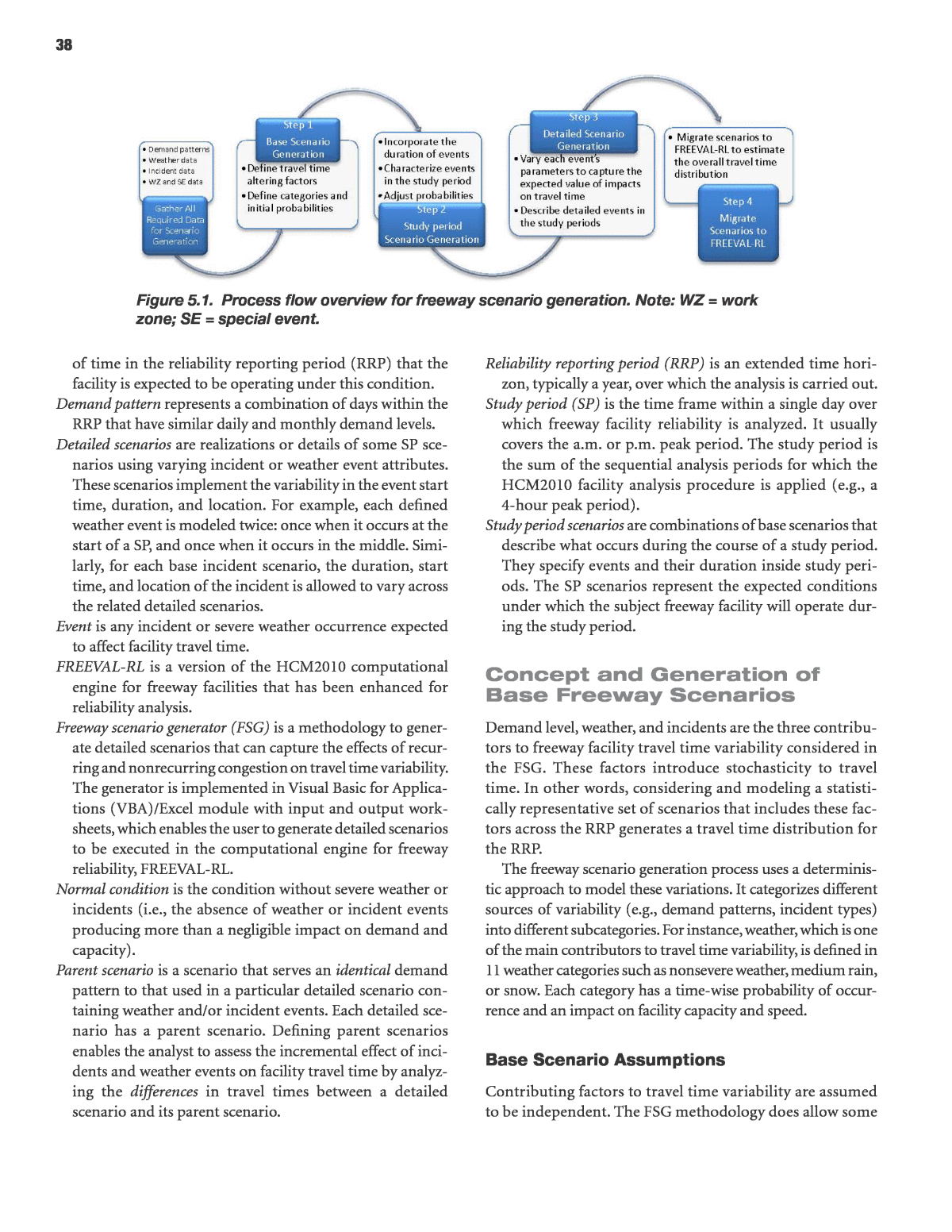
37 C h a p t e r 5 This chapter discusses the development of scenario genera- tors for freeway facilities and urban streets. It is divided into the following seven sections: 1. Introduction to freeway scenario development; 2. Concept and generation of base freeway scenarios; 3. Study period for freeway scenario generation; 4. Detailed freeway scenario generation; 5. Freeway scenario generation input for FREEVAL-RL; 6. Freeway summary and conclusions; and 7. Urban street scenario development. Introduction to Freeway Scenario Development The freeway scenario generator (FSG) generates and assigns initial probabilities to a number of base scenarios, Each base scenario is a combination of events that occur within a given time period, typically a weekday or (more likely) a few hours thereof. A base scenario probability is expressed as the fraction of time a particular combination of events takes place during the study period (SP) of interest (e.g., the a.m. or p.m. peak period). In this project, a scenario is a specific, unique realiza- tion of the study period, which may or may not contain a combination of weather and/or incident events. Base scenario probabilities are computed assuming independence between the events and at the initial stage and do not take into account the actual event duration. The base scenarios only account for the categories of weather and/or incidents. Therefore, the initial probabilities must be adjusted to account for the actual event duration and, in some cases, the scenario definition requires detailed adjustment of the event durations. This adjustment process is extensive and complex. The FSG is a deterministic approach to scenario genera- tion. This deterministic approach enumerates different oper- ating conditions of a freeway facility on the basis of different combinations of factors which affect travel time. The distinct sets of operational conditions are expressed as operational scenarios or, simply, scenarios. Four principal steps explain the construction of the scenario generation process for free- way facility analysis, as depicted in Figure 5.1. The FSG can work both in data-rich and data-poor envi- ronments, as well as in data environments that lie between the two extremes. In the data-rich case, the user is asked to input as much local data as possible. When local data are unavailable, the FSG relies on national defaults to generate the scenarios. At a minimum, the user must enter information regarding the subject facility seed file demand, geographic location, and detailed geometrics. The minimum data requirements are similar to the data requirements for most current HCM analysis procedures. Demand is entered into the FREEVAL-RL seed file. Detailed data such as daily and monthly demand variations are also needed. The FSG allows the user to enter facility-specific demand data or to use national default values for demand pat- tern definitions. The FSG also provides 10-year average weather data for 101 metropolitan areas (based on weather data from 99 airports), which users can apply in the absence of site- specific weather data. In addition, the FSG provides a flexible procedure for incident data entry that enables the analyst to use as much or as little facility-specific data as is appropriate for characterizing the probability of various incident types. More detailed information on incident probability is avail- able in Appendix F. Basic Definitions Analysis period (AP) is the 15-min time interval for which segment and facility operations are calculated in the HCM2010 freeway facility methodology. Base scenarios enumerate the mutually exclusive states or combinations of demand, weather, incident, work zone, and special event categories that occur on a freeway facility. The d/c probability of each scenario indicates the portion Scenario Generator Development
38 of time in the reliability reporting period (RRP) that the facility is expected to be operating under this condition. Demand pattern represents a combination of days within the RRP that have similar daily and monthly demand levels. Detailed scenarios are realizations or details of some SP sce- narios using varying incident or weather event attributes. These scenarios implement the variability in the event start time, duration, and location. For example, each defined weather event is modeled twice: once when it occurs at the start of a SP, and once when it occurs in the middle. Simi- larly, for each base incident scenario, the duration, start time, and location of the incident is allowed to vary across the related detailed scenarios. Event is any incident or severe weather occurrence expected to affect facility travel time. FREEVAL-RL is a version of the HCM2010 computational engine for freeway facilities that has been enhanced for reliability analysis. Freeway scenario generator (FSG) is a methodology to gener- ate detailed scenarios that can capture the effects of recur- ring and nonrecurring congestion on travel time variability. The generator is implemented in Visual Basic for Applica- tions (VBA)/Excel module with input and output work- sheets, which enables the user to generate detailed scenarios to be executed in the computational engine for freeway reliability, FREEVAL-RL. Normal condition is the condition without severe weather or incidents (i.e., the absence of weather or incident events producing more than a negligible impact on demand and capacity). Parent scenario is a scenario that serves an identical demand pattern to that used in a particular detailed scenario con- taining weather and/or incident events. Each detailed sce- nario has a parent scenario. Defining parent scenarios enables the analyst to assess the incremental effect of inci- dents and weather events on facility travel time by analyz- ing the differences in travel times between a detailed scenario and its parent scenario. Reliability reporting period (RRP) is an extended time hori- zon, typically a year, over which the analysis is carried out. Study period (SP) is the time frame within a single day over which freeway facility reliability is analyzed. It usually covers the a.m. or p.m. peak period. The study period is the sum of the sequential analysis periods for which the HCM2010 facility analysis procedure is applied (e.g., a 4-hour peak period). Study period scenarios are combinations of base scenarios that describe what occurs during the course of a study period. They specify events and their duration inside study peri- ods. The SP scenarios represent the expected conditions under which the subject freeway facility will operate dur- ing the study period. Concept and Generation of Base Freeway Scenarios Demand level, weather, and incidents are the three contribu- tors to freeway facility travel time variability considered in the FSG. These factors introduce stochasticity to travel time. In other words, considering and modeling a statisti- cally representative set of scenarios that includes these fac- tors across the RRP generates a travel time distribution for the RRP. The freeway scenario generation process uses a determinis- tic approach to model these variations. It categorizes different sources of variability (e.g., demand patterns, incident types) into different subcategories. For instance, weather, which is one of the main contributors to travel time variability, is defined in 11 weather categories such as nonsevere weather, medium rain, or snow. Each category has a time-wise probability of occur- rence and an impact on facility capacity and speed. Base Scenario Assumptions Contributing factors to travel time variability are assumed to be independent. The FSG methodology does allow some Figure 5.1. Process flow overview for freeway scenario generation. Note: WZ = work zone; SE = special event.
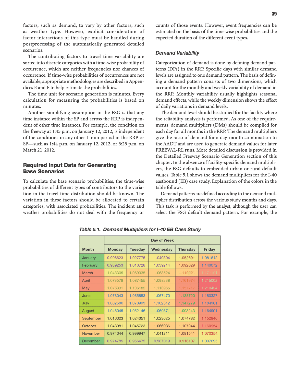
39 factors, such as demand, to vary by other factors, such as weather type. However, explicit consideration of factor interactions of this type must be handled during postprocessing of the automatically generated detailed scenarios. The contributing factors to travel time variability are sorted into discrete categories with a time-wise probability of occurrence, which are neither frequencies nor chances of occurrence. If time-wise probabilities of occurrences are not available, appropriate methodologies are described in Appen- dices E and F to help estimate the probabilities. The time unit for scenario generation is minutes. Every calculation for measuring the probabilities is based on minutes. Another simplifying assumption in the FSG is that any time instance within the SP and across the RRP is indepen- dent of other time instances. For example, the condition on the freeway at 1:45 p.m. on January 12, 2012, is independent of the conditions in any other 1-min period in the RRP or SPâsuch as 1:44 p.m. on January 12, 2012, or 3:25 p.m. on March 21, 2012. Required Input Data for Generating Base Scenarios To calculate the base scenario probabilities, the time-wise probabilities of different types of contributors to the varia- tion in the travel time distribution should be known. The variation in these factors should be allocated to certain categories, with associated probabilities. The incident and weather probabilities do not deal with the frequency or counts of those events. However, event frequencies can be estimated on the basis of the time-wise probabilities and the expected duration of the different event types. Demand Variability Categorization of demand is done by defining demand pat- terns (DPs) in the RRP. Specific days with similar demand levels are assigned to one demand pattern. The basis of defin- ing a demand pattern consists of two dimensions, which account for the monthly and weekly variability of demand in the RRP. Monthly variability usually highlights seasonal demand effects, while the weekly dimension shows the effect of daily variations in demand levels. The demand level should be studied for the facility where the reliability analysis is performed. As one of the require- ments, demand multipliers (DMs) should be compiled for each day for all months in the RRP. The demand multipliers give the ratio of demand for a day-month combination to the AADT and are used to generate demand values for later FREEVAL-RL runs. More detailed discussion is provided in the Detailed Freeway Scenario Generation section of this chapter. In the absence of facility-specific demand multipli- ers, the FSG defaults to embedded urban or rural default values. Table 5.1 shows the demand multipliers for the I-40 eastbound (EB) case study. Explanation of the colors in the table follows. Demand patterns are defined according to the demand mul- tiplier distribution across the various study months and days. This task is performed by the analyst, although the user can select the FSG default demand pattern. For example, the Table 5.1. Demand Multipliers for I-40 EB Case Study Month Day of Week Monday Tuesday Wednesday Thursday Friday January 0.996623 1.027775 1.040394 1.052601 1.081612 February 0.939253 1.010728 1.039214 1.092029 1.140072 March 1.043305 1.069335 1.063524 1.110921 1.171121 April 1.073578 1.087455 1.098238 1.161974 1.215002 May 1.076331 1.106182 1.113955 1.157717 1.210434 June 1.078043 1.085853 1.067470 1.138720 1.180327 July 1.082580 1.070993 1.102512 1.147279 1.184981 August 1.046045 1.052146 1.060371 1.093243 1.164901 September 1.016023 1.024051 1.023625 1.074782 1.152946 October 1.048981 1.045723 1.066986 1.107044 1.160954 November 0.974044 0.999947 1.041211 1.081541 1.070354 December 0.974785 0.956475 0.987019 0.916107 1.007695
40 demand pattern for the I-40 EB case study was found to be sea- sonal across the monthly dimension. Furthermore, demand on Mondays, Tuesdays, and Wednesdays could be considered as one group, while Thursdays and Fridays were unique and clas- sified as two additional, separate groups. The demand pattern definition for I-40 EB (Table 5.2) is based on comparing demand levels and categorizing days of the week and months of the year according to the demand level shown in Table 5.1. The text color entries in Table 5.1 reflect the same collection of patterns. To estimate the probability of each demand pattern, the fraction of the RRP (in minutes) with a certain demand pat- tern is divided by the total RRP duration. Table 5.3 presents a schematic of FSG demand patterns associated with the I-40 EB case study. The demand pattern number (shown in paren- theses following the date) provides a simple indicator of each dayâs demand level. The FSG begins with the first calendar day of the RRP and assigns a demand pattern number to each day within the RRP. The probability of demand pattern Z, expressed as pD(Z), is computed by using Equation 5.1. Sum of SP minutes within demand pattern Sum of SP minutes in RRP (5.1)DPp Z Z( ) = For example, the probability of occurrence of demand pat- tern 5 at any time in the RRP is shown below: 5 13 6 60 261 6 60 4.98%DPp ( ) = Ã Ã Ã Ã = where the number of SPs (or days) with demand pattern 5 is 13, SP is equal to 6 hours, and the total number of SPs in the RRP (or days in analysis) is 261. Weather Variability In the HCM2010, weather events are divided into 16 categories (including normal). Five categories have a negligible effect on the performance of the freeway facility and travel time. The remaining 11 categories are considered in this methodology. The probabilities of these 11 categories are stated by month, which enables the analyst to incorporate the effect of seasonal changes in the weather into the reliability analysis. A detailed discussion about the generation of nationwide weather catego- ries for freeway reliability analysis can be found in Appendix E. In data-rich environmentsâin which analysts have access to detailed local weather dataâthe probability of a weather category is computed using Equation 5.2. Weather categories are mutually exclusive, so when two or more categories can be identified for the same time period (e.g., low visibility and heavy rain), the event is assigned to the category with largest capacity reduction effect in Equation 5.2. Weather in each category is called weather type. , Sum of all SP durations in minutes in month that weather type is present Sum of all SP durations in minutes in month (5.2) p i j j i j w ( ) ( )= Where pw(i, j) is the probability of encountering weather type i in month j. In the absence of local data, the FSG Table 5.2. Demand Pattern Configuration for I-40 EB Case Study Monday Tuesday Wednesday Thursday Friday January 1 1 1 2 3 February 1 1 1 2 3 March 4 4 4 5 6 April 4 4 4 5 6 May 4 4 4 5 6 June 7 7 7 8 9 July 7 7 7 8 9 August 7 7 7 8 9 September 10 11 11 12 12 October 10 11 11 12 12 November 10 11 11 12 12 December 1 1 1 2 3
41 provides a VBA module and weather database for comput- ing the probability of different weather types as a function of the facilityâs geographic location, and time of day coincident with the SP. The weather database includes 10-year averages of hourly logs for 101 metropolitan areas in the United States. Table 5.4 presents the weather probabilities for the I-40 EB case study in 2010. For exam- ple, the probability of a medium rain event between 2:00 and 8:00 p.m. in May 2010 is shown to be pw (Med Rain, 5) = 1.951%. When using the 10-year average weather probabilities, a threshold is set in the FSG to remove weather events with very low probabilities, thus reducing the overall number of scenarios. The threshold is specified by the user. Any weather event with a probability lower than the thresh- old is removed, and its probability is assigned to the remaining weather events proportionally on the basis of their probabilities. The default value for this threshold is 0.1%. Entering a value of zero for the threshold disables its functionality. It is not recommended to enter a large value for this threshold, because doing so could result in a significant loss of fidelity in the estimated travel time distribution. Incident Variability Incidents are categorized according to their severity or capacity impacts. For the purpose of scenario generation, six categories are defined for characterizing the incident effect. Because of the complexity of estimating the proba- bility of incidents on the freeway facility, the FSG provides multiple options for analysts to use the available incident or crash data to generate the monthly incident probabili- ties. The resolution of incident probabilities is months. The Table 5.3. Partial Listing of Demand Patterns Associated with I-40 EB Case Study Week No. Month Monday Tuesday Wednesday Thursday Friday 1 January N/A N/A N/A N/A 1/1/2010 (3) 2 January 1/4/2010 (1) 1/5/2010 (1) 1/6/2010 (1) 1/7/2010 (2) 1/8/2010 (3) 3 January 1/11/2010 (1) 1/12/2010 (1) 1/13/2010 (1) 1/14/2010 (2) 1/15/2010 (3) 4 January 1/18/2010 (1) 1/19/2010 (1) 1/20/2010 (1) 1/21/2010 (2) 1/22/2010 (3) 5 January 1/25/2010 (1) 1/26/2010 (1) 1/27/2010 (1) 1/28/2010 (2) 1/29/2010 (3) 6 February 2/1/2010 (1) 2/2/2010 (1) 2/3/2010 (1) 2/4/2010 (2) 2/5/2010 (3) 7 February 2/8/2010 (1) 2/9/2010 (1) 2/10/2010 (1) 2/11/2010 (2) 2/12/2010 (3) 8 February 2/15/2010 (1) 2/16/2010 (1) 2/17/2010 (1) 2/18/2010 (2) 2/19/2010 (3) 9 February 2/22/2010 (1) 2/23/2010 (1) 2/24/2010 (1) 2/25/2010 (2) 2/26/2010 (3) 10 March 3/1/2010 (4) 3/2/2010 (4) 3/3/2010 (4) 3/4/2010 (5) 3/5/2010 (6) 11 March 3/8/2010 (4) 3/9/2010 (4) 3/10/2010 (4) 3/11/2010 (5) 3/12/2010 (6) 12 March 3/15/2010 (4) 3/16/2010 (4) 3/17/2010 (4) 3/18/2010 (5) 3/19/2010 (6) 13 March 3/22/2010 (4) 3/23/2010 (4) 3/24/2010 (4) 3/25/2010 (5) 3/26/2010 (6) 14 April 3/29/2010 (4) 3/30/2010 (4) 3/31/2010 (4) 4/1/2010 (5) 4/2/2010 (6) 15 April 4/5/2010 (4) 4/6/2010 (4) 4/7/2010 (4) 4/8/2010 (5) 4/9/2010 (6) 16 April 4/12/2010 (4) 4/13/2010 (4) 4/14/2010 (4) 4/15/2010 (5) 4/16/2010 (6) 17 April 4/19/2010 (4) 4/20/2010 (4) 4/21/2010 (4) 4/22/2010 (5) 4/23/2010 (6) 18 May 4/26/2010 (4) 4/27/2010 (4) 4/28/2010 (4) 4/29/2010 (5) 4/30/2010 (6) 19 May 5/3/2010 (4) 5/4/2010 (4) 5/5/2010 (4) 5/6/2010 (5) 5/7/2010 (6) 20 May 5/10/2010 (4) 5/11/2010 (4) 5/12/2010 (4) 5/13/2010 (5) 5/14/2010 (6) 21 May 5/17/2010 (4) 5/18/2010 (4) 5/19/2010 (4) 5/20/2010 (5) 5/21/2010 (6) 22 May 5/24/2010 (4) 5/25/2010 (4) 5/26/2010 (4) 5/27/2010 (5) 5/28/2010 (6) 23 June 5/31/2010 (4) 6/1/2010 (7) 6/2/2010 (7) 6/3/2010 (8) 6/4/2010 (9) 24 June 6/7/2010 (7) 6/8/2010 (7) 6/9/2010 (7) 6/10/2010 (8) 6/11/2010 (9) Note: N/A = not applicable.
42 probability of incident type i in month j is computed from Equation 5.3: p i j j i j ( ) ( )=, Sum of all SP durations in minutes in month that incident type is present Sum of all SP durations in minutes in month (5.3) Inc If local incident probabilities are not available for a facility, then using either local crash rates or crash rates predicted from the HERS model in combination with an incident-to- crash ratio enables one to calculate the probabilities of differ- ent incident types. A queuing model is used for computing the probability of having incidents in the freeway facilities. A more detailed discussion of incident generation is provided in Appendix F. Table 5.5 depicts the probabilities associated with incidents for the I-40 EB case study. For example, the probability of an incident causing a single-lane closure anywhere on the facility between 2:00 and 8:00 p.m. in May 2010 is pInc (One-Lane Closure, 5) = 7.64%. Independence of Time Instances (Minutes) and Joint Events The stated probabilities of events are associated with and connected to the frequency of event occurrence. How- ever, the FSG computes the time-wise probabilities of encountering different categories of contributors to varia- tions in travel time. Specifically, the probability of each sub- category yields the chance of exposure to a specified category at any instance in the RRP or SP. From a mathematical per- spective, the duration of the weather or incident events are not considered at the base scenario generation stage. Any time instance in the RRP or SP is therefore assumed to be independent of any other time instance. More precisely, if the state of any contributor to travel time variation at any time instance is known, the methodology assumes that this state has no effect on the probability of encountering any other contributing factor in the remaining time instances. The units for measuring the probabilities of subcategories are minutes. Therefore, the time instance refers to any 1-min time interval in the SP or RRP. This basic assumption that all contributing factors to travel time variation are independent allows one calculate the prob- ability of a base scenario as the product of the probability of all contributing factors. For example, given the assumption that there is no dependency between certain demand levels and different weather types, the methodology combines these categories and multiplies their probabilities to generate the different operational conditions and associated probabilities for the freeway facility. These scenarios are referred to as base scenarios. Equation 5.4 is used to calculate the joint probability of each base scenario based on the scenarioâs probability of weather and incident events, assuming independence between factors. Table 5.4. Weather Probabilities for I-40 EB Case Study Month Weather Categories (based on HCM2010 Chapter 10: Freeway Facilities) Medium Rain (%) Heavy Rain (%) Light Snow (%) Light to Medium Snow (%) Medium to Heavy Snow (%) Heavy Snow (%) Severe Cold (%) Low Visibility (%) Very Low Visibility (%) Minimal Visibility (%) Normal Weather (%) January 1.970 0.000 5.911 0.000 0.000 0.000 0.000 0.000 0.000 0.000 92.1182 February 2.717 0.000 0.000 0.000 0.000 0.000 0.000 2.174 0.000 0.000 95.1087 March 0.505 0.000 1.010 0.000 0.000 0.000 0.000 0.000 0.000 0.000 98.4848 April 0.000 0.543 0.000 0.000 0.000 0.000 0.000 0.000 0.000 0.000 99.4565 May 1.951 1.951 0.000 0.000 0.000 0.000 0.000 0.000 0.000 0.000 96.0976 June 0.505 0.505 0.000 0.000 0.000 0.000 0.000 0.000 0.000 0.000 98.9899 July 0.500 0.500 0.000 0.000 0.000 0.000 0.000 0.000 0.000 0.000 99.0000 August 0.000 0.000 0.000 0.000 0.000 0.000 0.000 0.000 0.000 0.000 100.0000 September 4.255 0.532 0.000 0.000 0.000 0.000 0.000 0.000 0.000 0.000 95.2128 October 0.000 0.000 0.000 0.000 0.000 0.000 0.000 0.000 0.000 0.000 100.0000 November 0.000 0.000 0.000 0.000 0.000 0.000 0.000 0.000 0.000 0.000 100.0000 December 0.000 0.000 7.805 0.488 0.000 0.000 0.000 0.000 0.000 0.000 91.7073
43 Prob Demand Level , Weather Type , Incident Type Prob Demand Level Prob Weather Type Prob Incident Type (5.4) i j k i j k { } { } { } { }= à à Note that some dependencies between event occurrences are inherent through the use of the calendar. It is intuitively obvious and observable from data that both demand levels (in Table 5.2) and weather conditions (in Table 5.4) are associated with the calendar. Therefore, a correlational (not a causal) relationship exists between the two factors. Incident probabil- ities are also tied to the prevailing demand levels, again pro- viding a correlation through the calendar. In fact, the user can enter different monthly crash or incident rates in the FSG to express further associated weather and incident probabilities. Aggregation of Probabilities Across Demand Patterns Each base scenario is characterized by a demand pattern, weather event, and incident type. Given this characterization, the probability of each scenario can be computed. However, the probability of weather and incidents are given by month, while demand is categorized according to a demand pattern defini- tion that is not necessarily monthly. Thus, the probabilities of weather and incidents must be aggregated across the demand patterns. The demand patternâdependent probabilities of weather and incidents are computed on the basis of Equations 5.5 and 5.6. The equations are illustrated with numerical calcu- lations for incorporating the effects of medium rain (weather event 1) and one-lane closure (incident event 3) probabilities into the demand pattern prevalent on Thursdays in the spring season (DP = 5) for the I-40 EB case study facility. In the equa- tions below, j refers to a month, u to a demand pattern, and i to a weather or incident type. , , , , (5.5)DP DPDP DPDP â â ( ) ( ) ( )( ) = à ε ε p u i p i j N u j N u j w wj j 5, 1 1, 5, 5, 0.00505 4 0 5 0.01951 4 13 0.756% (5.6) DP DP3 5 DP3 5p p j N j N j w wj j â â ( ) ( ) ( )( ) = à = à + à + à = = = The probability of a base scenario is the product of the aggregated probabilities of each contributing factor. Equa- tion 5.1 can be rewritten in the form of Equation 5.7: p z W x u p z p x i p u iw ( ) ( ) ( )( ) = = = = à à DP , , Inc , , (5.7) Base DP DP Inc DP As an example, the probability of observing demand pat- tern 5 along with medium rain and one-lane closure condi- tions can be computed as shown below: DP 5, 1, Inc 3 5 5, 1 5, 3 0.0498 0.00756 0.07561 4.561 10 Base DP DP Inc DP 5 p W p p pw( ) ( ) ( )( )= = = = à à = à à = à â Table 5.5. Incident Probabilities for I-40 EB Case Study Month Probability of Different Incident Types No Incident (%) Shoulder Closure (%) One-Lane Closure (%) Two-Lane Closure (%) Three-Lane Closure (%) Four-Lane Closure (%) January 66.42 23.30 7.06 1.79 1.43 0.00 February 66.36 23.34 7.08 1.79 1.43 0.00 March 65.10 24.18 7.36 1.87 1.49 0.00 April 63.79 25.05 7.66 1.94 1.56 0.00 May 63.87 25.00 7.64 1.94 1.55 0.00 June 64.53 24.56 7.49 1.90 1.52 0.00 July 64.10 24.85 7.59 1.93 1.54 0.00 August 65.30 24.04 7.32 1.86 1.48 0.00 September 65.97 23.60 7.17 1.82 1.45 0.00 October 65.04 24.22 7.38 1.87 1.50 0.00 November 66.79 23.05 6.98 1.77 1.41 0.00 December 68.56 21.86 6.59 1.67 1.33 0.00
44 In fact, the base scenarios describe the operational condi- tion of the freeway facility and the probability associated with it. The probability of a base scenario specifies the expected portion of time that the freeway facility is subject to operat- ing at the scenario-specified conditions. Thus, each base scenario presents an expected travel time and its associated probability. By modeling these scenarios and measuring their travel times, a discrete distribution of expected travel times is generated. This expected discrete travel time distribution is used to assess the reliability of the freeway facility. The exam- ple for the I-40 EB case study generated 225 distinct base sce- narios describing the facilityâs operational condition. Figure 5.2 presents a schematic of the FSG output, which shows each base scenario and its probability (column with an arrow). Study Period for Freeway Scenario Generation While the base scenarios describe the general conditions under which the facility will operate during a study period (e.g., a weather event will occur sometime during the study period and an incident will take place sometime and somewhere on the facility), they lack the specificity that enables an analyst to model the eventsâ effect in the FREEVAL-RL computational engine. This gives rise to the term study period (SP) scenarios, in which event durations are specified and adjustments to the base scenario probabilities take place. To summarize, each base scenario is associated with a unique SP scenario. The only difference in the two is the probability associated with each type (see the column to the right of the one with the arrow in Figure 5.2). This section describes the computations required to achieve the transition from a base scenario to an SP scenario, beginning with a simple example that motivates the need to develop SP scenarios. Motivation Using a Simple Example Facility Description Consider a freeway facility consisting of 10 HCM segments. The reliability reporting period contains 50 workday Fridays, each of which has the same demand pattern. The study period is 3:00 to 7:00 p.m., resulting in 16 15-min analysis periods. For simplicity, one severe weather condition and one inci- dent are considered in the reliability reporting period: medium rain with a total duration of 600 min, and one-lane closure with a total duration of 900 min. Table 5.6 summarizes these conditions with respect to their time-wise probabilities. The time-wise probability expresses the likelihood an event will occur in any time instance during the reliability reporting period. This probability translates into any time period that can be reported. For example, if the duration of the study period is 4 hours, then the expectation is that the event will be present for Figure 5.2. FSG schematic showing base scenarios for I-40 case study.
45 a period of time equal to its probability times the study period duration. The term time-wise distinguishes this probability from other types of probabilities, such as VMT-wise, count- wise, or length-wise probabilities. Base Scenario Development The base scenario generation procedure is employed to gen- erate different operational conditions on the freeway facility. These conditions are assumed to be independent. Table 5.7 summarizes the operational conditions associated with the base scenarios in this example. The base scenarios in this form are not ready to be provided to the HCM freeway facil- ity methodology because they do not contain any of the criti- cal event attributes that affect travel time (e.g., location, duration, start time). The joint probabilities of these operational conditions are also time-wise. If any time instance across all study periods in the reliability reporting period is chosen, it will yield a no- severe-weather and no-incident condition (demand-only scenario) with a probability of almost 88%. Figure 5.3 depicts the probabilities associated with each base scenario. Study Period Scenario Development Next, the event durations are introduced. According to his- torical data, the average durations are 49 min and 32 min for the one-lane closure incident and the medium rain weather event, respectively. Because the HCM freeway facilities method uses 15-min analysis periods, these average durations are rounded to 45 min and 30 min, respectively. To accommodate the four combinations of weather and inci- dent events being modeled, four SP scenarios are defined. Mod- eling these four study periods guarantees that all the operational condition characteristics are accounted for at the correct time- wise probabilities. A weight (or probability)âthe SP scenario probabilityâis assigned to the study periods to be fully consis- tent with the specified likelihood of the operational conditions (base scenarios). The objective is to determine what weight to give to each of the four SP scenarios so that the resulting travel time dis- tribution represents the facilityâs prespecified operational conditions. In other words, considering the base scenario probability values p1, p2, p3, p4, and the respective durations of Table 5.6. Example Time-Wise Probabilities of Event Occurrences Event Time-Wise Probability of Occurrence Weather Event Medium rain 600 min duration 50 study periods 4 h study period 60 min h 0.05 Ã Ã = Nonsevere weather 1 - 0.05 = 0.95 Incident Event One-lane closure 900 min duration 50 study periods 4 h study period 60 min h 0.075 Ã Ã = No incident 1 - 0.075 = 0.925 Table 5.7. Example Base Scenarios Base Scenario Number Weather Condition Incident Condition Base Scenario Description Probability 1 Nonsevere No incident Demand-only p1 = 0.95 Ã 0.925 = 0.87875 2 Medium rain No incident Demand and weather p2 = 0.05 Ã 0.925 = 0.04625 3 Nonsevere One lane closed Demand and incident p3 = 0.95 Ã 0.075 = 0.07125 4 Medium rain One lane closed Demand, weather, and incident p4 = 0.05 Ã 0.075 = 0.00375 Sum = 1 Figure 5.3. Distribution of initial scenario categories.
46 the events and the study period, what should the study period scenario probability values p1, p2, p3, and p4 be to provide consistent time-based probabilities throughout? The study period scenario probabilities should be selected in such a way that the likelihood of the conditions modeled is identical to the base scenario probabilities. To achieve this result, Equations 5.8 through 5.11 must be satisfied for each of the base scenarios. The logic behind each equation is to equalize the proportion of time each study period scenario should be represented, according to the base scenario probabilities, recognizing that periods of no- incident or no-severe-weather conditions exist in all four study periods. For example, in SP scenario 2, severe weather occurs in two of the 16 analysis periods, meaning that no-incident and no- severe-weather conditions are present in the remaining 14 analysis periods. Similarly, in SP scenario 3, an incident is present in three of the 16 analysis periods and no-incident conditions are present in the remaining 13 analysis periods. Finally, in SP scenario 4, representing combined weather and incident events, the longer of the two durations (in this case, three analysis periods) determines when an event is present, while the shorter of the two durations (in this case, two analy- sis periods) determines how long the combined weather and incident condition occurs. Equation 5.8 provides the equality relationship for base sce- nario 1, representing a demand-only condition. The probabil- ity of this scenario must equal the combined probabilities of the demand-only portions of the four study period scenarios. p ( ) ( ) ( ) ( )= â pi + â pi + â pi + â pi16 016 16 216 16 316 16 316 (5.8)1 1 2 3 4 SP scenario 1 has 16 demand-only analysis periods out of 16 total analysis periods. SP scenario 2 has 14 such analysis periods out of 16, and so on. The proportion of demand-only analysis periods in each SP scenario is multiplied by that sce- narioâs probability pi. Equation 5.9 provides the equality relationship for base scenario 2, representing a combined demand and severe- weather-event condition. This condition does not occur at all in SP scenarios 1, 3, or 4, and occurs during only two of the 16 analysis periods in SP scenario 2. Therefore, 2 16 (5.9)2 2p ( )= pi Similarly, a combined demand and incident condition occurs during three of the 16 analysis periods in SP scenario 3 and in one of the 16 analysis periods in SP scenario 4. A combined demand, weather, and incident condition occurs during two of the 16 analysis periods in SP scenario 4. Equations 5.10 and 5.11 give the respective equality relation- ships for base scenarios 3 and 4. 3 16 1 16 (5.10)3 3 4p ( ) ( )= pi + pi 2 16 (5.11)4 4p ( )= pi With four equations and four unknowns, which are p1, p2, p3, and p4, Equation 5.8 can be solved for the various pi val- ues, yielding the following results: 0.23; 0.37; 0.37; and 0.03.1 2 3 4pi = pi = pi = pi = When those pi values are assigned to the four specified SP scenarios, the resulting travel time distribution yields facility travel times consistent with the intended distribution of operational conditions. Note the large difference between p1 (88%) and p1 (23%). This result does not mean that normal conditions have been reduced by that amount in the SP scenarios. It simply reflects that âpiecesâ of p1 exist in all four SP scenarios, as indicated in the first of the four equilibrium equations (Equation 5.8). The large differences between p2 and p2 and between p3 and p3 are similarly explained: those two study period scenarios also con- tain many no-incident, no-severe-weather analysis periods. The set of equilibrium equations could potentially yield infeasible results (meaning one of the resulting pi values is negative). That could occur if the likelihood of the weather or incident event is high and the expected event duration is short. In those cases, the duration of the event should be increased, or more than one event per study period should be modeled. Detailed Scenario Development The final step in the scenario generation process is to develop the detailed scenarios. Weather events have two possible start times; incidents have three possible start times, three possible durations, and two possible locations. Each possible combi- nation is assumed to occur with equal probability. Figure 5.4 depicts one detailed scenario from each of the four study periods associated with a study period scenario. Each study period is 4 hours (or 16 analysis periods) long, consistent with the specified duration. The figure shows the expected duration and location of the weather and incident events associated with the detailed scenarios. At this point, sufficient information is available to model the facility by using the HCM freeway facilities method, as the weather and incident events have been fully specified according to start time, duration, and affected segments. In addition, the probabilities of each detailed scenario have been determined,
47 Detailed scenario probability = Ï1 Detailed scenario probability = Ï2/2 Detailed scenario probability = Ï3/18 Detailed scenario probability = Ï4/18 Demand Demand and weather Demand and incident Demand, weather, and incident Figure 5.4. Event occurring during each analysis period of selected detailed scenarios.
48 allowing the resulting travel time distribution to be properly aggregated. The final results of applying the adjusted probabilities for the I-40 EB case study are shown in Table 5.8. Note that the sum of the probabilities for the demand pattern is preserved in both cases, with only the allocation of probabilities across the 20 scenarios varying. Also, as noted earlier, the weights for the no-severe-weather, no-incident scenario decreased by a factor of 1,000 from 8.8% to 0.0084%, as shown in Table 5.9. To model weather and incident events, the start time, dura- tion, and location of the events on the facility should be esti- mated. Although the start time and precise location of an event can be determined in the latter steps of the analysis, the event duration is critical in adjusting the base scenario prob- ability to avoid biasing the resulting distribution, as shown in the simple example above. A special algorithm is applied to model incident and weather events inside each study period. Event duration is usually low compared with the duration of the study period. The algo- rithm adjusts the probabilities of base scenarios that have events shorter than their study period. All weather and incident events are modeled assuming their mean duration only. If a single mean event duration is inadequate to honor the initial event probability P, with adjusted P > 1.0, another event of the same duration is appended in the study period. Thus, the algo- rithm determines the number of events and the durations that are required to match the stated probabilities. Algorithm Assumptions The following assumptions are built into the event modeling algorithm: ⢠Incident event durations may be altered during detailed scenario generation, without altering the study period probabilities. This assumption is not overly severe, since Table 5.8. I-40 EB Base Scenarios and Probabilities for Demand Pattern 1 Incident Category Weather Category Sum of Probabilities (%) Nonsevere Weather (0) (%) Medium Rain (1) (%) Low Visibility (2) (%) Light to Medium Snow (3) (%) Light Snow (4) (%) No incident (0) 8.8473650 0.14309 0.06633 0.01666 0.44710 9.52054 Shoulder closure (1) 3.00484 0.05025 0.02332 0.00531 0.14825 3.23197 One-lane closure (2) 0.90935 0.01524 0.00707 0.00160 0.04479 0.97805 Two-lane closure (3) 0.23029 0.00386 0.00179 0.00040 0.01134 0.24769 Three-lane closure (4) 0.18409 0.00309 0.00143 0.00032 0.00906 0.19799 Sum of probabilities 13.17593 0.21553 0.09995 0.02430 0.66053 14.17625 Table 5.9. I-40 EB Adjusted Scenario Probabilities for Demand Pattern 1 Incident Category Weather Category Sum of Probabilities (%) Nonsevere Weather (0) (%) Medium Rain (1) (%) Low Visibility (2) (%) Light to Medium Snow (3) (%) Light Snow (4) (%) No incident (0) 0.00843 0.88275 0.21562 0.10565 0.22294 1.43539 Shoulder closure (1) 4.00645 0.60302 0.27983 0.06371 0.88950 5.84251 One-lane closure (2) 3.63738 0.18290 0.08489 0.01919 0.53746 4.46183 Two-lane closure (3) 1.37323 0.03090 0.01076 0.00324 0.06802 1.48615 Three-lane closure (4) 0.87098 0.02470 0.00860 0.00259 0.04350 0.95037 Sum of probabilities 9.89649 1.72426 0.59970 0.19437 1.76142 14.17625
49 the three possible incident durations are selected to be at, below, and above the originally assumed mean duration. ⢠Modeling in FREEVAL requires all events to be rounded to the nearest 15-min increment, to be consistent with HCM analysis period durations. This process introduces some errors and bias to the reliability calculations; however, the algorithm accounts for this bias and eliminates its effects. Scenario Categories In general, scenarios are divided into four categories: ⢠Demand-only (normal condition) scenarios (Category 1 scenarios); ⢠Weather-only scenarios (Category 2 scenarios); ⢠Incident-only scenarios (Category 3 scenarios); and ⢠Combined incident and weather scenarios (Category 4 scenarios). This categorization is needed to execute the probability adjustment procedure in the generation of SP scenarios. In gen- eral, the first category usually has a high probability of occur- rence. As an example, Category 1 scenarios have a probability of about 64% in the I-40 EB case study. Demand patterns are modeled using the demand adjustment factors (DAFs). Each scenario (basic, study period, and detailed) has an associated demand multiplier (DM) that applies to all segments and time periods. To model the effects of weather and incident events, appropriate capacity adjustment factors (CAFs) and free-flow speed adjustment factors (SAFs) are applied to the affected seg- ments and time periods. For incidents, the number of open lanes should also be adjusted according to the type of incident. The remaining sections focus on (1) the generation of base sce- narios in the FSG; (2) the challenge of modeling events in the study periods, by mapping and changing the probability vector for the base scenarios; and (c) detailed scenarios that are entered into the computational engine FREEVAL-RL. Subsets of Base Scenarios In a facility with N demand patterns, all base scenarios can be divided into N subsets. The subsets are mutually exclusive, and their union covers all base scenarios. The methodology pro- posed for adjusting SP scenario probabilities applies to each subset separately. Table 5.10 presents one such subset associ- ated with demand pattern 1 for the I-40 EB case study (the sum of probabilities is 14.18% as per Table 5.8 and Table 5.9). Conceptual Approach The methodology for the SP scenario probability adjustment creates weather or incident events in the study period with a predetermined duration. The remaining time periods in that study period actually describe another scenario from Table 5.10 (usually the parent scenario, base scenario 4). Therefore, each SP scenario is associated with more than one base scenario. Figure 5.5 depicts an example in which an SP scenario rep- resents three base scenario categories, demand-only (during t1 and t4), demand and weather (during t3), and demand, weather, and incident (during t2). If the probability of the occur- rence of this SP scenario is given as P, then Equations 5.12 through 5.15 give the relationships between the probabilities of base and SP scenarios. Category 1 Demand Only Base Scenarioâs Probability SP (5.12) 1 4t t( ) ( ) = â à + Category 2 Weather Only Base Scenarioâs Probability SP (5.13) 3t( ) ( ) = â à Category 3 Incident Only Base Scenarioâs Probability 0 (5.14) ( ) = t( ) ( ) = â à Category 4 Weather and Incident Base Scenarioâs Probability SP (5.15) 2 As shown in the Equations 5.12 through 5.15, the relation- ship between the base and SP scenario probabilities is one- to-one. In this method, the base scenariosâ probabilities are known and the SP scenario probabilities (P) are calculated. Core SP Scenario Generation: Probability Adjustments The core of the methodology relies on adjusting event durations. SP scenarios, with their adjusted probabilities, provide a freeway system operation similar to the base sce- narios from a travel time perspective. The methodology consists of 10 steps. The data presented in Table 5.10 are used throughout this section as an example for following the steps in the methodology. Figure 5.6 shows the meth- odologyâs process flow. Step 1: Select the Desired Subset of Base Scenarios Associated with a Specific Demand Pattern All base scenarios associated with demand pattern 1 are grouped into one subset. The data in Table 5.11 shows five
50 Table 5.10. Subset of Base Scenarios Associated with Demand Pattern 1 Base Scenario No. Demand Pattern No. Weather Label Incident Label Probability of Base Scenario (%) Scenario Category No. 4 1 Nonsevere weather No incident 8.84736 1 16 1 Nonsevere weather Shoulder closure 3.00484 3 28 1 Nonsevere weather One-lane closure 0.90935 3 29 1 Light snow No incident 0.44710 2 42 1 Nonsevere weather Two-lane closure 0.23029 3 45 1 Nonsevere weather Three-lane closure 0.18409 3 48 1 Light snow Shoulder closure 0.14825 4 49 1 Medium rain No incident 0.14309 2 68 1 Low visibility No incident 0.06633 2 74 1 Medium rain Shoulder closure 0.05025 4 77 1 Light snow One-lane closure 0.04479 4 88 1 Low visibility Shoulder closure 0.02332 4 96 1 Light to medium snow No incident 0.01666 2 99 1 Medium rain One-lane closure 0.01524 4 104 1 Light snow Two-lane closure 0.01134 4 117 1 Light snow Three-lane closure 0.00906 4 120 1 Low visibility One-lane closure 0.00707 4 128 1 Light to medium snow Shoulder closure 0.00531 4 138 1 Medium rain Two-lane closure 0.00386 4 146 1 Medium rain Three-lane closure 0.00309 4 163 1 Low visibility Two-lane closure 0.00179 4 164 1 Light to medium snow One-lane closure 0.00160 4 166 1 Low visibility Three-lane closure 0.00143 4 203 1 Light to medium snow Two-lane closure 0.00040 4 209 1 Light to medium snow Three-lane closure 0.00032 4 Figure 5.5. Typical study period with incident and weather event (Category 4 scenario).
51 Figure 5.6. Probability adjustment methodology for SP scenarios.
52 weather and five incident categories. The incident categories are no incident, shoulder closure, one-lane closure, two-lane closure, and three-lane closure. Weather events are non- severe weather, medium rain, low visibility, light to medium snow, and light snow. The parent scenario of this subset is the first base scenario in Table 5.10 (base scenario 4). The parent scenario has a relatively large probability of occur- rence compared with other scenarios. Table 5.11 presents combinations of weather and incident events for the speci- fied subset along with their probabilities. As shown in Table 5.11, the sum of probabilities for all scenarios is 14.176%. Therefore, the sum of the adjusted probabilities for the SP scenarios must also be 14.176%. Different categories of base scenarios are shown with different background colors. Green represents Category 1, blue represents Categories 2 and 3, and pink represents Category 4. Step 2: Calculate the Time Differences Between Weather and Incident Event Durations Denote twi as the duration of weather event i, and tjinc as the duration of incident type j. The indices for each weather and incident categories are shown in parentheses in Table 5.11. Modeling any weather or incident event requires its duration to be rounded to the nearest 15-min increment. In this sec- tion, âRound (t)â symbolizes the rounded value of t to its nearest 15-min value. According to the definition of Category 4 base scenarios, the effects of weather and incidents apply to the freeway facil- ity with the same duration. In reality, they might have differ- ent durations. Therefore, the durations of weather and incident events are compared in this step and the differences are calculated. For each Category 4 scenario, wij and Dij are defined on the basis of Equations 5.16 and 5.17. Min Round , Round (5.16)incij iw j( )( )( )Ï = Ï Ï Round Round (5.17)incij iw j( )( )â = Ï â Ï Thus, wij represents the time that both weather and inci- dent events occur in Category 4 base scenarios. Table 5.12 and Table 5.13 present the durations of weather and incident events for the I-40 EB case study. Table 5.14 and Table 5.15 show the values of wij and Dij for the I-40 EB case study, based on Equations 5.16 and 5.17. Table 5.11. Combinations of Weather and Incidents Associated with Demand Pattern 1 and Their Probabilities Incident Category ( j ) Weather Category (i) Sum of Probabilities (%) Nonsevere Weather (0) (%) Medium Rain (1) (%) Low Visibility (2) (%) Light to Medium Snow (3) (%) Light Snow (4) (%) No incident (0) 8.847365 0.14309 0.06633 0.01666 0.44710 9.52054 Shoulder closure (1) 3.00484 0.05025 0.02332 0.00531 0.14825 3.23197 One-lane closure (2) 0.90935 0.01524 0.00707 0.00160 0.04479 0.97805 Two-lane closure (3) 0.23029 0.00386 0.00179 0.00040 0.01134 0.24769 Three-lane closure (4) 0.18409 0.00309 0.00143 0.00032 0.00906 0.19799 Sum of probabilities 13.17593 0.21553 0.09995 0.02430 0.66053 14.17625 Table 5.12. I-40 EB Duration of Different Weather Categories Weather Category Expected Duration (min) Rounded Value to Nearest 15-min Increment Medium rain 42.9 45 Low visibility 57.2 60 Light to medium snow 46.6 45 Light snow 134.3 135 Table 5.13. I-40 EB Duration of Different Incident Categories Incident Category Expected Duration (min) Rounded Value to Nearest 15-min Increment Shoulder closure 32 30 One-lane closure 34 30 Two-lane closure 53 60 Three-lane closure 69 75
53 Step 3: Calculate Category 4 SP Scenario Probability Denote pij and pij as the probabilities of base scenarios and SP scenarios, respectively. The duration of the study period is symbolized by SP. If there is only a single weather event co - inciding with a single incident event in the SP scenario then the relationship between the SP scenarioâs probability and the base scenarioâs probability is in the form of Equation 5.18: SP (5.18)pij ij ij( )= pi Ã Ï Equation 5.18 defines a one-to-one relationship between the SP scenario and base scenario probabilities. It indicates that the probability of a base scenario is the proportion of time that has the same condition in the SP, multiplied by the probability of the SP scenario. Although the condition imme- diately after the event is not completely the same as that rep- resented by the parent (nonsevere weather and no incident) scenario (e.g., the impact of wet pavement after a rain event has ended), that effect is ignored in the method. Nevertheless, the bias imposed by this assumption is considered negligible. Equation 5.19 gives the probability of the SP scenarios as a function of the probability of the base scenarios. SP (5.19)pij ij ij pi = Ã Ï ï£« ï£ï£¬   Step 3 calculates pij values for all Category 4 scenarios, as illustrated in Table 5.16. Table 5.14. I-40 EB Calculated î¶ij Values Incident Category Medium Rain (1) Low Visibility (2) Light to Medium Snow (3) Light Snow (4) Shoulder closure (1) 30 30 30 30 One-lane closure (2) 30 30 30 30 Two-lane closure (3) 45 60 45 60 Three-lane closure (4) 45 60 45 75 Note: Calculated values are in minutes. Table 5.15. I-40 EB Calculated îij Values Incident Category Medium Rain (1) Low Visibility (2) Light to Medium Snow (3) Light Snow (4) Shoulder closure (1) 15 30 15 105 One-lane closure (2) 15 30 15 105 Two-lane closure (3) 15 0 15 75 Three-lane closure (4) 30 15 30 60 Note: Calculated values are in minutes. Table 5.16. Adjusted Probabilities (pij ) for Category 4 Scenarios Incident Category ( j ) Weather Category (i) Sum of Probabilities (%) Normal Weather (0) Medium Rain (1) (%) Low Visibility (2) (%) Light to Medium Snow (3) (%) Light Snow (4) (%) No incident (0) N/A N/A N/A N/A N/A N/A Shoulder closure (1) N/A 0.60302 0.27983 0.06371 1.77900 2.72556 One-lane closure (2) N/A 0.18290 0.08489 0.01919 0.53746 0.82444 Two-lane closure (3) N/A 0.03090 0.01076 0.00324 0.06802 0.11434 Three-lane closure (4) N/A 0.02470 0.00860 0.00259 0.04350 0.08202 Sum of probabilities N/A 0.87426 0.41448 0.09218 1.90197 3.7423 Note: N/A = not applicable.
54 Step 4: Check the Necessity for Modeling More than One Event in Category 4 Scenarios The sum of all probabilities generated in Step 3 for Cate- gory 4 scenarios should be less than the total sum of the base scenario probabilities. Otherwise, the SP scenarios must model more than one event (or overall duration) per study period as the only possible option to address this problem. Equation 5.20 should thus hold for proceeding with the methodology with no change in event durations (i.e., Step 5). (5.20) 1 to 4 1 to 4 0 to 4 0 to 4 pij i j ij i j â âpi < = = = = In Equation 5.20, i and j represent the weather and inci- dent category indices, respectively. For the I-40 EB case study, the total sum of probabilities of the subset associated with demand pattern 1 is 14.176%, which is equal to the sum of all base scenario probabilities. The sum of prob- abilities generated in Step 3 is 3.74%. The condition for continuing the methodology holds on the basis of Equation 5.20: 3.74% 14.176%< If the constraint in Equation 5.20 is not met, then the solu- tion to the problem lies in modeling more than one incident and weather event simultaneously. In that case, the process of modeling more than one event should be followed (i.e., increase the values of wij), and Steps 2 and 3 should be repeated to make sure that the sum of all probabilities is low enough to warrant proceeding with the rest of the methodol- ogy. Differences between durations of weather events and incidents should also be investigated. In some cases, the prob- lem is solved by repeating the shortest event (which is usually the incident). This process models two incidents concurrent with one weather event. If any such changes are made, Steps 2 and 3 should be repeated. Step 5: Calculate Residual Probabilities for Category 2 and 3 Scenarios Residual probabilities are imposed by the differences in dura- tions of the weather events and incidents in Category 4 sce- narios. In Step 3, the study period was modeled with weather events and incidents, together with a duration of wij and a probability pij. However, because weather events and incidents are likely to have different durations, the effect of the longer of the two events should be modeled to maintain accuracy. Denote Wi as a Category 4 scenario when the rounded weather event (i) duration is greater than the rounded inci- dentâs duration and Ij as a Category 4 scenario when the inci- dent (j) duration is greater than the weather event duration. Finally, a flag N is assigned whenever the rounded incident and weather durations are equal. For type N scenarios, the residual probabilities need not be computed. This step focuses only on type W and type I scenarios. Table 5.17 shows the vari- ous flags associated with the different weather event and inci- dent combinations for the I-40 EB case study. In this step, a portion of the probability of each weather- only (Category 2) scenario is assigned to the cell in the same column as the W-flagged scenarios, and a portion of the probability of incident-only (Category 3) scenarios is assigned to each cell in the same row as the I-flagged scenarios. The reason is that the generated SP scenarios in Step 3 not only represent Category 4 base scenarios, but some of them also represent Categories 2 and 3. Denote aij as an indicator variable, where i j Wijα =    1, if the flag of scenario with weather type and incident type is ; 0, Otherwise. (5.21) Table 5.17. I-40 EB Flags for Weather Events and Incident Scenarios Incident Category ( j ) Weather Category (i ) Normal Weather (0) Medium Rain (1) Low Visibility (2) Light to Medium Snow (3) Light Snow (4) No incident (0) N/A N/A N/A N/A N/A Shoulder closure (1) N/A W1 W2 W3 W4 One-lane closure (2) N/A W1 W2 W3 W4 Two-lane closure (3) N/A I3 N I3 W4 Three-lane closure (4) N/A I4 I4 I4 W4 Note: N/A = not applicable.
55 Denote bij as an indicator variable, where 1, if the flag of scenario with weather type and incident type is ; 0, Otherwise. (5.22) i j Iijβ =    In each column in Table 5.18, the probability residual in Category 4 scenarios assigned to Category 2 scenarios is cal- culated on the basis of Equation 5.23. Denote pâ²i as this residual probability: SP (5.23) 1 4 i ij ij ij j â ( )â²pi = pi Ãα à â = In each column in Table 5.18, the probability residual in the Category 4 scenarios assigned to Category 3 scenarios is calculated on the basis of Equation 5.24. Denote pâ³i as this residual probability. SP (5.24) 1 4 j ij ij ij i â ( )â²â²pi = pi à β à â = The purpose of using aij and bij is to filter the scenarios that have W or I flags. Table 5.18 presents the calculated values for residual probabilities in Step 5 for the I-40 EB case study. They indicate that Category 4 scenarios already account for a portion of Category 2 or 3 scenarios. These residual probabil- ities should therefore be subtracted from the initial base sce- nario probabilities. Step 6: Check that the Residual Probabilities Are Lower than Category 2 and 3 Initial Base Scenario Probabilities If pâ²i and pâ³j are greater than the probability of Category 2 and 3 scenarios, that means the impact of time difference between the duration of the weather event and the duration of the incident (Dij) is larger than the impact of the expected weather-only or incident-only base scenario. That means the shorter event must be modeled with a longer duration in Step 3, and the procedure needs to be restarted again from Step 3. To proceed to the next step, Equation 5.25 and Equa- tion 5.26 must hold. , 0 (5.25)p ij ijâ²â²pi < = , 0 (5.26)p ji ijâ²pi < = For the I-40 EB case study, substituting in Equation 5.25 for Category 2 scenarios gives ⢠0.5488% < 0.4471% (for light snow); ⢠0.0035% < 0.0167% (for light to medium snow); ⢠0.0304% < 0.0663% (for low visibility); and ⢠0.0328% < 0.1431% (for medium rain). It is evident in the top equation above that the condition has not been satisfied. For Category 3 scenarios, substituting in Equation 5.26 gives ⢠0.00103% < 0.03191% (for two-lane closure); and ⢠0.00082% < 0.02548% (for three-lane closure). Given these results, two shoulder closures must be mod- eled besides light snow in the Category 4 scenario associated with these two events. Table 5.19 shows the resulting new set of probabilities for SP scenarios. Now the condition in Equation 5.26 holds, allowing the procedure to move on: 0.3635% < 0.4471% (for light snow) Table 5.18. Residual Probabilities for Incident-Only or Weather-Only Scenarios Incident Category ( j ) Weather Category (i) Sum of Probabilities (%) Normal Weather (0) (%) Medium Rain (1) (%) Low Visibility (2) (%) Light to Medium Snow (3) (%) Light Snow (4) (%) No incident (0) N/A 0.03275 0.03039 0.00345 0.54880 0.61540 Shoulder closure (1) N/A 0.60302 0.27983 0.06371 1.77900 N/A One-lane closure (2) N/A 0.18290 0.08489 0.01919 0.53746 N/A Two-lane closure (3) 0.00142 0.03090 0.01076 0.00324 0.06802 N/A Three-lane closure (4) 0.00263 0.02470 0.00860 0.00259 0.04350 N/A Sum of probabilities 0.00405 N/A N/A N/A N/A N/A Note: N/A = not applicable.
56 Note that after modeling two incidents in the Category 4 scenario associated with light snow and shoulder closure, the wij and Dij values should be updated for that specific scenario. Step 7: Calculate Remaining Probabilities of Category 2 and 3 Scenarios To model events in Category 2 and 3 scenarios, their base sce- nario remaining probabilities (in addition to the Category 4 residuals) should be calculated. These probabilities show the portion of base scenario probabilities that is not modeled in Category 4 SP scenarios. In the next step, an adjustment of the SP Category 2 and 3 scenario probabilities will be calculated. Equations 5.27 and 5.28 give the remaining probabilities for Category 2 and 3 scenarios. pij i= â â²pi Remainder Probabilities for Weather Only Scenarios (5.27) pij j= â â²â²pi Remainder Probabilities for Incident Only Scenarios (5.28) Checking the probabilities in Step 6 ensures that the prob- abilities are positive in Step 7. Table 5.20 presents the remain- der probabilities for Category 2 and 3 scenarios. Step 8: Adjust Category 2 and 3 Probabilities In Step 7, the base scenario remainder probabilities of Category 2 or 3 scenarios were calculated. In Step 8, those probabilities are adjusted on the basis of Equation 5.29 to Table 5.19. Corrected Residual Probabilities for Category 2 Scenarios Incident Category ( j ) Weather Category (i) Sum of Probabilities (%) Normal Weather (0) (%) Medium Rain (1) (%) Low Visibility (2) (%) Light to Medium Snow (3) (%) Light Snow (4) (%) No incident (0) N/A 0.03275 0.03039 0.00345 0.36349 0.4300 Shoulder closure (1) N/A 0.60302 0.27983 0.06371 0.88950 N/A One-lane closure (2) N/A 0.18290 0.08489 0.01919 0.53746 N/A Two-lane closure (3) 0.00142 0.03090 0.01076 0.00324 0.06802 N/A Three-lane closure (4) 0.00263 0.02470 0.00860 0.00259 0.04350 N/A Sum of probabilities 0.00405 N/A N/A N/A N/A N/A Note: N/A = not applicable. Table 5.20. Remainder Probability of Incident-Only (Category 3) and Weather-Only (Category 2) Scenarios Incident Category ( j ) Weather Category (i) Sum of Probabilities (%) Normal Weather (0) (%) Medium Rain (1) (%) Low Visibility (2) (%) Light to Medium Snow (3) (%) Light Snow (4) (%) No incident (0) N/A 0.11034 0.03594 0.01321 0.08360 0.24309 Shoulder closure (1) 0.60302 N/A N/A N/A N/A N/A One-lane closure (2) 0.18290 N/A N/A N/A N/A N/A Two-lane closure (3) 0.03090 N/A N/A N/A N/A N/A Three-lane closure (4) 0.02470 N/A N/A N/A N/A N/A Sum of probabilities 0.95186 N/A N/A N/A N/A N/A Note: N/A = not applicable.
57 generate SP scenario probabilities for Categories 2 and 3. Because pij is the remaining probability in Step 7, the probability of a Category 2 scenario is computed by using Equation 5.29. SP Round (5.29)0 0pi i iw i w( )pi = Ã Ï Ï ï£« ï£ï£¬   The same process is used to calculate the probability of Category 3 scenarios using Equation 5.30. SP Round (5.30)0 0 inc pj j j( )pi = Ã Ï ï£« ï£ï£¬   After applying Step 8 (and confirming in Step 9 that no further changes in the number of modeled events are needed), the remaining probabilities are assigned to the Category 1, or normal condition scenario. Table 5.21 shows the adjusted probabilities for Category 2 and 3 scenarios for the I-40 EB case study. Step 9: Check the Necessity of Modeling More than One Event per Study Period in Category 2 and 3 Scenarios As shown in Table 5.21, the overall sum of probabilities, excluding Category 1, is 53.49% which is greater than 14.18%, the sum of the base scenario probabilities. Thus, some Cate- gory 2 or 3 scenarios need to have more than one event occur to decrease their probabilities. Based on Equations 5.29 and 5.30, if the event duration increases, then the corresponding SP scenario probability will decrease. A rational criterion for selecting scenarios in which to model more than one event is their current generated prob- abilities. In Table 5.22, some incident-only scenarios have relatively large probabilities. In the I-40 EB case study, the Table 5.21. Adjusted Probabilities for Category 2, 3, and 4 Scenarios Incident Category ( j ) Weather Category (i) Sum of Probabilities (%) Normal Weather (0) (%) Medium Rain (1) (%) Low Visibility (2) (%) Light to Medium Snow (3) (%) Light Snow (4) (%) No incident (0) N/A 0.88275 0.21562 0.10565 0.22294 1.43539 Shoulder closure (1) 36.05807 0.60302 0.27983 0.06371 0.88950 37.89413 One-lane closure (2) 10.91215 0.18290 0.08489 0.01919 0.53746 11.73660 Two-lane closure (3) 1.37323 0.03090 0.01076 0.00324 0.06802 1.48615 Three-lane closure (4) 0.87098 0.02470 0.00860 0.00259 0.04350 0.95037 Sum of probabilities 49.22287 1.72426 0.59970 0.19437 1.76142 53.49420 Note: N/A = not applicable. Table 5.22. Adjusting Incident-Only Scenarios to Have Two Incidents (Red Cells) Incident Category ( j ) Weather Category (i) Sum of Probabilities (%) Normal Weather (0) (%) Medium Rain (1) (%) Low Visibility (2) (%) Light to Medium Snow (3) (%) Light Snow (4) (%) No incident (0) N/A 0.88275 0.21562 0.10565 0.22294 1.43539 Shoulder closure (1) 4.00645 0.60302 0.27983 0.06371 0.88950 5.84251 One-lane closure (2) 3.63738 0.18290 0.08489 0.01919 0.53746 4.46183 Two-lane closure (3) 1.37323 0.03090 0.01076 0.00324 0.06802 1.48615 Three-lane closure (4) 0.87098 0.02470 0.00860 0.00259 0.04350 0.95037 Sum of probabilities 9.89649 1.72426 0.59970 0.19437 1.76142 14.16781 Note: N/A = not applicable.
58 Category 3 (incident-only) scenarios are the targets. Increas- ing the duration of the incident event in two scenarios that are shown in the cells with the red background in Table 5.22 brings the sum of the probabilities to less than 14.18%. The red cells show the scenarios where more than one incident is modeled consecutively, which is equivalent to longer incident duration. Nine shoulder closures and three one-lane closures are modeled in red cells. Step 10: Calculate Category 1 Scenario Probability The difference between the sum of probabilities of base sce- narios and the current sum of probabilities should be assigned to the Category 1 (parent) scenario. Table 5.23 presents the adjusted probabilities for all SP scenarios for demand pattern 1 in the I-40 EB case study. This set of adjusted probabilities is guaranteed to generate an unbiased travel time distribution. Some other assump- tions, such as using the average duration of events, could still impose some error and bias into the analysis. These issues are listed in the future work section of this chapter. In general, the use of this methodology will result in a decrease in the prob- abilities of Category 1 scenarios from the base scenario val- ues, and increase the probabilities of scenarios with any events, as evident from the summary results in Table 5.24, which summarize the combined results of applying the meth- odology across all 12 demand patterns. Given the best information available to the research team, a total of 225 base scenarios were generated for the I-40 EB case study in the FSG. The 225 SP scenarios were used to generate 2,508 detailed scenarios. By grouping similar scenarios together, the total number of scenarios was reduced to 2,058 for modeling in FREEVAL-RL, as explained next. Detailed Freeway Scenario Generation As discussed in the base scenario generation section of this chapter, the travel time distribution generated by this meth- odology expresses the expected variation in travel time for the conditions defined by the base scenarios. Therefore, vari- ations in event duration, start time, and location should be incorporated into the FSG methodology. Certain predefined values of these parameters are varied in the scenarios to cap- ture their effect on the expected travel time distribution. Specifically, incident impacts on freeway facilities are sen- sitive to the facility geometry (e.g., number of lanes, segment type, and segment length) as well as the prevailing demand level. Clearly, the effect of an incident on travel time can vary depending on the facility level of service, with higher impacts anticipated when the facility is operating near capacity. Thus, to capture the real effect of an incident on the freeway facility, the eventâs location, start time, and duration should be allowed to vary. Two possible start times are assumed for the incident, along with three possible durations and three possible loca- tions along the facility. Table 5.23. Final Adjusted Probabilities for Demand Pattern 1, I-40 EB Case Study Incident Category ( j ) Weather Category (i) Sum of Probabilities (%) Normal Weather (0) (%) Medium Rain (1) (%) Low Visibility (2) (%) Light to Medium Snow (3) (%) Light Snow (4) (%) No incident (0) 0.00843 0.88275 0.21562 0.10565 0.22294 1.43539 Shoulder closure (1) 4.00645 0.60302 0.27983 0.06371 0.88950 5.84251 One-lane closure (2) 3.63738 0.18290 0.08489 0.01919 0.53746 4.46183 Two-lane closure (3) 1.37323 0.03090 0.01076 0.00324 0.06802 1.48615 Three-lane closure (4) 0.87098 0.02470 0.00860 0.00259 0.04350 0.95037 Sum of probabilities 9.89649 1.72426 0.59970 0.19437 1.76142 14.17625 Table 5.24. Comparison of Base and Study Period Scenario Probabilities Statistic Base Scenarios SP Scenarios Number of scenarios 225 225 Probability of Category 1 scenarios 63.64% 2.15% Probability of Category 2 scenarios 1.86% 7.57% Probability of Category 3 scenarios 33.56% 81.08% Probability of Category 4 scenarios 0.94% 9.20%
59 Weather events, however, are assumed to affect the entire facility at once. Thus, the two principal weather parameters in developing detailed scenarios are the event start time and dura- tion. Two possible start times are assumed, along with one pos- sible duration. Detailed Scenario Probabilities In computing the detailed scenario probabilities, the system operatorâs point of view is taken into consideration when developing the travel time distribution. What the system operator is interested in is the aggregate performance of the facility over each 15-min analysis period during the reliability reporting period. Referring back to the final adjusted probabilities in Table 5.23, the Category 1 probability for demand pattern 1 is about 0.0084%. Since the duration of the study period in the case study is 6 hours, or 24 analysis periods, the facility travel time in each 15 min for the Category 1 scenario is given a probability equal to 0.0084%/24 = 0.00035%. For a Category 2 scenarioâfor example, a medium rain eventâthe probability is computed as 0.8828%/(2 Ã 24) = 0.0184%. The reason for dividing by 2 is that this scenario will be executed twice in FREEVAL-RL, once with the event at the start of the study period, and again with the event in the middle of the study period. For a Category 3 scenarioâsay a shoulder closure incidentâ the probability is computed as 4.006%/(2 Ã 3 Ã 3 Ã 24) = 0.00927%. The reason for dividing by 18 is that the shoulder closure will be modeled 18 times in FREEVAL-RL, with three different locations, three durations, and two start times. For a Category 4 scenarioâsay shoulder closure with medium rainâthe probability is computed as 0.603%/ (2 Ã 3 Ã 3 Ã 24) = 0.0014%. The reason for dividing by 18 is that the shoulder closure will be modeled 18 times in FREEVAL-RL, at three different locations, with three dura- tions and two start times. Because the weather event is started at the same time that the incident is started, further division by 2 is not needed. Table 5.25 summarizes the vari- ation in different modeling parameters in the detailed sce- nario generation. Postprocessing Detailed Scenarios Given the designation of incident types, some detailed sce- narios are not feasible. This happens when a facility does not have the same number of cross-sectional lanes through- out. For example, by varying the location of incidents, the scenario could result in a total segment closure (e.g., by modeling a two-lane closure incident on a two-lane seg- ment). These infeasible scenarios are purged from the final list of detailed scenarios, and their probabilities are reas- signed proportionally to the remaining detailed scenarios on the basis of their probability of occurrence. In the I-40 EB case study, because the last basic segment has only two lanes, scenarios with two or more lanes closed cannot occur on that segment. In addition, when the variance and mean of incidents are small, the incident durations in different scenarios can become identical after rounding to the near- est 15 min. When this happens, the two detailed scenarios can be merged and their probabilities summed. In summary, postprocessing the detailed scenarios generally reduces the number of detailed scenarios that must be evaluated in FREEVAL-RL. Estimating the Maximum Number of Scenarios Equation 5.31 estimates the maximum number of detailed scenarios that could be generated. Because of the merging of some demand patterns and the application of minimum thresholds for inclusion, some weather events and incidents may have a zero probability. The total number of scenarios as a function of different impacting factors is the following: 1 1 1 1 (5.31) Demand Demand Weather Weather Demand Incidents Incidents Demand Weather Incidents Incidents Weather N N N N C N N C N N N C C [ ] [ ] [ ] ) ) ) ) ( ( ( ( = + Ã â Ã + Ã â Ã + Ã â Ã â Ã Ã N denotes the total number of scenarios, while NWeather and NIncidents are the weather categories (11) and incident catego- ries (6) aggregated across demand patterns, respectively. Each incident category is expressed by 18 detailed scenarios (CIncidents), and each weather scenario is doubled (CWeather). With 12 default Table 5.25. Modeling Parameters in FSG Methodology Event Factor Variations and Levels Description Weather Start time Beginning of study period Middle of study period Incident Start time Beginning of study period Middle of study period Location First basic segment Midpoint basic segment Last basic segment Duration 25th percentile incident duration 50th percentile incident duration 75th percentile incident duration Incident duration fol- lows a lognormal distribution.
60 demand patterns, a maximum of 22,932 detailed scenarios can be generated. ( ) ( ) ( )= + à à + à à + à à à à = 12 12 10 2 12 5 18 12 10 5 18 2 22,932 N For the I-40 EB case study, the procedure generated 2,508 detailed scenarios. Note that some scenarios can be further merged. Table 5.26 summarizes the detailed scenario statistics. Freeway Scenario Generation Input for FreeVaL-rL This section discusses the parameters that are passed to FREEVAL-RL for each detailed scenario. Geometry, capacity, and demand data are three basic pieces of information that FREEVAL-RL needs to analyze a facility. In this section, the research team selected a detailed scenario to use as an example. Detailed scenario 2117 from the I-40 EB case study includes a medium rain event and a two-lane closure incident. Table 5.27 shows the specification of this detailed scenario. Two items can vary by scenario: the adjusted FFS and the operational number of lanes. Different weather and incident events can change the base FFS. Therefore, by passing a free- flow speed adjustment factor (SAF), FREEVAL-RL adjusts the FFS for certain analysis periods in the study period. Also, if a detailed scenario has a lane closure, then the number of lanes is adjusted for that specific scenario on the incident segment during the analysis periods when the incident is present. Fig- ure 5.7 depicts the number of adjusted lanes for detailed sce- nario 2117 in the I-40 EB case study. Segment 23 is a four-lane basic segment at the midpoint of the facility. In analysis peri- ods 12 through 15, highlighted in red, the number of lanes for that segment is reduced to two. Demand Adjustments Through the detailed seed file, the FSG has access to hourly demand values for all analysis periods in a SP. The only adjustment needed is to include the daily demand multiplier for the seed SP, which is denoted by DMSeed. Then, the hourly demand on segment i, time period t, for detailed scenario k is computed as shown in Equation 5.32. ( ) ( ) ( )= ï£ï£¬ DM DMDP (5.32)SeedSeedD D i t k i t k Thus, in the data-rich approach, the FSG essentially passes DMDP DMSeed kï£«ï£ ï£¶ï£¸ to FREEVAL-RL. Figure 5.8 shows the demand multipliers for I-40 EB case study scenario 2117. Capacity and Speed Adjustments Modeling an incident or weather event on a freeway facility in FREEVAL-RL is done by inserting (1) its capacity adjust- ment factor (CAF), (2) its speed adjustment factor (SAF), and (3) in the case of a lane closure, the number of operating lanes for the segment that has the incident or lane blockage. From a capacity perspective, the FSG determines the capacity loss resulting from closed lanes (incidents or work zones) by specifying the number of operating lanes and the period of time the reduced number of lanes are in effect. In addition, the frictional effect on the remaining open lanes is then defined as the CAF. In addition to adjusting capacity, the free-flow speed should be adjusted for any incident or weather event. This task is done by changing the SAF in FREEVAL-RL. The literature includes no evidence that incidents affect the prevailing free-flow speed, although severe weather conditions can have a significant impact. Therefore, a default value of 1 (i.e., no adjustment) is used as the free-flow speed adjustment factor for incidents. The FSG enables the analyst to define local CAFs and SAFs for different incidents and weather events. In the absence of Table 5.26. Statistics for Detailed Scenarios Generated for I-40 EB Case Study Scenario Type Number Percent Category 1 demand-only scenarios 12 0.5% Category 2 demand and incident scenarios 648 25.8% Category 3 demand and weather scenarios 66 2.6% Category 4 demand, incident, and weather scenarios 1,782 71.1% Sum 2,508 Table 5.27. General Information for Detailed Scenario 2117 Category Description Weather type Medium rain Weather event start time Middle of SP Weather event duration (min) 45 Weather event CAF 0.928 Weather event SAF 0.930 Incident type Two-lane closure Incident start time Middle of SP Incident duration (min) 60 Incident location Midpoint of facility Per open lane incident CAF 0.667 Incident SAF 1.00
61 Figure 5.7. Operational number of lanes under detailed scenario 2117. Figure 5.8. Demand multipliers (DMs) for I-40 EB detailed scenario 2117. local data, HCM2010 default CAFs for different types of weather and incidents can be substituted. When generating the combined capacity drop for a segment that is simultane- ously affected by an incident and weather, the associated CAFs and SAFs are multiplied. CAFjinc and CAFiw are defined as the CAFs for type j inci- dents and type i weather events, respectively. For each seg- ment and 15-min period, the joint CAF is computed by using Equation 5.33. CAF CAF CAF (5.33)i nc j w i = Ã Similar calculations are considered for speed adjustments. SAFjinc and SAF i w are defined as the SAFs for type j incidents and type i weather events, respectively. Then for each segment and 15-min time period, the combined SAF is computed using Equation 5.34. SAF SAF SAF (5.34)inc= Ã j w i Figure 5.9 shows the CAF matrix generated by FSG, which is routed to FREEVAL-RL to adjust the capacity of the seg- ments in every time period. Note the combined effect of CAF for segment 23 in time periods 12 through 14. The 0.62 values are computed as 0.93 (weather) Ã 0.67 (incident). Figure 5.10 shows the SAF matrix generated by FSG, which is routed to FREEVAL-RL to adjust the free-flow speed of the segments in every time period.
62 Figure 5.9. CAF table for I-40 EB case study detailed scenario 2117. Figure 5.10. SAF table for I-40 EB case study detailed scenario 2117.
63 Freeway Summary and Conclusions The preceding sections of this chapter have presented the sce- nario generation process for evaluating travel time reliability on freeway facilities. In general, three factors affect travel time variability: traffic demand, weather, and incidents. The FSG converts these factors into an aggregated set of operational conditions on the facility, each with a predetermined proba- bility. The mathematical performance model starts from the development of base, study period, and detailed scenarios. The latter are forwarded to the computational engine FREEVAL-RL for estimating analysis period facility travel times. Although full automation has yet to be accomplished, the process readily lends itself to automation. The methodology combines the states of freeway opera- tion to model weather events and incidents more realisti- cally. Other factors that affect a facilityâs capacity or demand can be dealt with in a similar manner. The methodology transforms the probability distribution of base scenarios (representing operational conditions) into another space synchronized with the study period. The methodology also includes the determination of the required number of events that needs to be modeled in all study periods. Changes in event duration are accounted for by a change in the proba- bility vector. Urban Street Scenario Development This section describes the scenario generation stage of the urban streets reliability methodology. Specifically, it describes the procedures used to create the scenarios that describe street and traffic conditions during the reliability reporting period. These procedures are as follows: ⢠Weather event procedure; ⢠Traffic demand variation procedure; ⢠Traffic incident procedure; and ⢠Scenario file generation procedure. Weather Event Procedure The weather event procedure is used to predict weather events (rain and snow) during the reliability reporting period. Also predicted is the time following each event that the pavement remains wet or covered by snow or ice. The presence of these conditions has been found to have an influence on running speed and intersection saturation flow rate. These effects are described later in this section. The sequence of calculations in the weather event proce- dure is shown in Figure 5.11. The calculations proceed on a day-by-day basis in chronologic order. If a day is deter- mined to have a weather event, its start time and duration are recorded for later use in the traffic incident procedure. Thereafter, each analysis period is evaluated in chrono- logic order for any given day with a weather event. If the analysis period is associated with a weather event, then the event type (i.e., rain or snow), precipitation rate (i.e., inten- sity), and pavement status (i.e., wet or snow-covered) are recorded for later use in the scenario file generation procedure. The weather event procedure is based on the weather sta- tistics in the following list. These statistics represent averages by month for 10 or more years. Default values are provided in the software implementation of the reliability methodology. They are described in Appendix H. ⢠Total normal precipitation; ⢠Total normal snowfall; ⢠Number of days with precipitation of 0.01 in. or more; ⢠Normal daily mean temperature; and ⢠Precipitation rate. The weather event procedure consists of a series of calcula- tion steps. A random number is used in several of the steps. All random numbers have a real value that is uniformly dis- tributed from 0.0 to 1.0. Step 1: Precipitation Prediction The answer to the question of whether precipitation falls in a given day is based on a Monte Carlo method and an assumed binomial distribution of daily weather occurrence (n = 1.0, x = 1.0, p = p(precip)). The probability of precipitation for any given day is computed by using Equation 5.35. ( ) =precip Ndp Nd (5.35)p m m m where p(precip)m = probability of precipitation in any given day of month m; Ndpm = number of days with precipitation of 0.01 in. or more in month m; and Ndm = total number of days in month m. For each day considered, Equation 5.36 is checked to deter- mine whether precipitation occurs. ( ) ( ) ⥠< No precipitation if Rp precip Precipitation if Rp precip (5.36) p p d d where Rpd is equal to a random number for precipitation for day d.
64 Step 2: Precipitation Type If precipitation occurs, then Equation 5.37 is used to estimate the average temperature during the weather event for the subject day. ( )= = µ = Ï =ânormal Rg , , (5.37), 1T p T sd m d m T where Td,m = average temperature for day d of month m, °F; Rgd = random number for temperature for day d; T â m = normal daily mean temperature in month m, °F; sT = standard deviation of daily mean tem- perature in a month (= 5.0), °F; and normal-1(p, µ, s) = value associated with probability p for cumulative normal distribution with mean µ and standard deviation s. The average temperature for the day is used to determine whether the precipitation is in the form of rain or snow. The temperature variation during the day can influence this determination. However, modeling this influence is rational- ized to add more analytic sophistication than is justified for the reliability evaluation. Therefore, for each day considered in the reliability reporting period, Equation 5.38 is used to determine whether the precipitation that day is in the form of rain or snow. Rain if 32 F Snow if 32 F (5.38) , , ⥠° < ° T T d m d m The normal daily mean temperature is obtained from the National Climatic Data Centerâs Comparative Climatic Data (NCDC 2011a). This statistic is tabulated by month of year for 284 U.S. cities and territories. It represents the average of the daily mean temperatures in a given month. The standard deviation of the daily mean temperature sT rep- resents the variability of the daily mean temperature for a given month. This statistic was computed for seven U.S. cities. The cit- ies represent all combinations of north/south and east/middle/ west regions of the country. The daily mean temperature data were obtained from the National Climatic Data Center (NCDC Figure 5.11. Weather event procedure.
65 2011c). The standard deviation for the seven cities is shown in Figure 5.12 as a function of the normal daily mean temperature. Twelve observations were recorded for each city. The general trend in the data suggests that the standard deviation decreases slightly with an increase in the normal daily mean temperature (R2 = 0.28). However, the standard deviation did not vary with temperature for cities on the West Coast. On the basis of this examination, a constant value of 5.0°F is recommended for sT for the reliability evaluation. Step 3: Rain Intensity When evaluated on an hourly basis, the rainfall rate (i.e., intensity) can be highly variable. The gamma distribution has the ability to replicate nonnegative random variants that are highly variable. Equation 5.39 is used to estimate the rainfall rate during a rain event. ( )= = µ = Ï =ârr gamma Rr , rr , (5.39), 1 rr,p sd m d m m where rrd,m = rainfall rate for the rain event occur- ring on day d of month m, in./h; Rrd = random number for rainfall rate for day d; rr _ m = precipitation rate in month m, in./h; srr,m = standard deviation of precipitation rate in month m (= 1.0 rr _ m), in./h; and gamma-1(p, µ, s) = value associated with probability p for cumulative gamma distribution with mean µ and standard deviation s. The average precipitation rate (and its standard deviation) is based on time periods when precipitation is falling. Thus, the average precipitation rate represents an average for all hours in which precipitation is falling (and excludes any hours in which precipitation is not falling). Binned hourly precipitation data were obtained from the National Climatic Data Center to examine the standard deviation of precipitation rate (NCDC 2011b). Data were obtained for 5,900 weather stations collectively representing all 50 states. An examination of the data indicates that the standard deviation of the precipitation rate is about equal to the average precipitation rate. The general trend in this rela- tionship is shown in Figure 5.13. For the reliability evaluation, the standard deviation is conservatively assumed to equal the average precipitation rate (i.e., srr,m = 1.0rr _ m). This approach excludes the very rare intense storm event and increases the intensity slightly of those events that do occur. Equation 5.40 is used to estimate the total amount of rain- fall for a rain event. This analysis assumes that each day with precipitation has one rain event. ( )= = µ = Ï =âtr gamma Rt , tr , (5.40), 1 tr,p sd m d m m with =tr tp Ndp (5.41)m m m ( )= Smaller of 2.5 tr , 0.65 (5.42)tr,s m m where trd,m = total rainfall for the rain event occurring on day d of month m, in./event; Rtd = random number for rainfall total for day d (= Rrd); tr __ m = average total rainfall per event in month m, in./event; str,m = standard deviation of total rainfall in month m, in./event; and tpm = total normal precipitation for month m, in. Total rainfall for a rain event represents the product of the rainfall rate and the rain event duration. Thus, the total rain- fall amount is highly correlated with the rainfall rate. For the 0 2 4 6 8 10 12 14 0 20 40 60 80 100 Normal Daily Mean Temperature, degrees St an da rd D ev ia tio n of Te m pe ra tu re , d eg re es Figure 5.12. Standard deviation of daily mean temperature (°F). y = 1.1481x R2 = 0.9075 0.00 0.05 0.10 0.15 0.20 0.00 0.05 0.10 0.15 0.20 Precipitation Rate, in/hr St an da rd D ev ia tio n of Pr ec ip ita tio n R at e, in /h r Each data point represents data for 100 weather stations. Figure 5.13. Standard deviation of precipitation rate.
66 reliability evaluation, total rainfall is assumed to be perfectly correlated with rainfall rate such that they share the same random number. This approach may result in slightly less variability in the estimated total rainfall; however, it precludes the occasional calculation of unrealistically long or short rain events. The standard deviation of total rainfall combines the vari- ability of rainfall rate and rainfall duration. As a result, its value is defined partly by the manner in which the rainfall rate is defined (i.e., measured) and the rain event is modeled. The approach used to calibrate the standard deviation of total rainfall is to compare the resulting estimates of rainfall rate and rain duration for a range of values. The calculation of rainfall duration is described in the next step. Harwood et al. (1988) examined rainfall rate and duration data for 99 weather stations in 22 metropolitan areas through- out the United States. The relationship they found between the two variables is shown in Figure 5.14 using the solid trend line. Equations 5.39 through 5.43 were used to compute the rainfall rate and duration for various percentile events (i.e., the random number for Equations 5.39 and 5.40 was set to a common percentile value). The percentile values included 0.01, 0.1, 0.5, 0.9, and 0.99. The relationship between the computed rainfall rate and duration is shown in Figure 5.14. The circles represent the data points corresponding to various percentile values. The standard deviation relationship shown in Equation 5.42 was derived to provide the best fit between the data points and the trend line representing the findings by Harwood et al. (1988). Step 4: Rainfall Duration Equation 5.43 is used to estimate the rainfall duration for a rain event. =dr tr rr (5.43), , , d m d m d m where drd,m is rainfall duration for the rain event occurring on day d of month m, h/event. The duration computed in Equation 5.43 is used in a sub- sequent step to determine whether an analysis period is asso- ciated with a rain event. To simplify the analytics in this subsequent step, it is assumed that no rain event extends beyond midnight. To ensure this outcome, the duration com- puted in Equation 5.43 is compared with the time duration between the start of the study period and midnight. The rainfall duration is then set to equal the smaller of the two values. Step 5: Start Time of Weather Event For the reliability methodology, the hour of day that the rain event starts is determined randomly. The start hour is com- puted using Equation 5.44: ( )= âts 24 dr (5.44), , ,Rd m d m s d where tsd,m is the start of rain event on day d of month m, in hours; and Rs,d is the random number for rain event start time for day d. The start time from Equation 5.44 is rounded to the near- est hour for 1-hour analysis periods or to the nearest quarter hour for 15-min analysis periods. Step 6: Wet-Pavement Duration Following a rain event, the pavement remains wet for some length of time. The presence of wet pavement can influence road safety by reducing surface-tire friction. Research by Harwood et al. (1988) indicates that wet-pavement time can be computed using Equation 5.45: = + +dw dr do dd (5.45), , , ,d m d m d m d m with ( )= â +dd 0.888 exp 0.0070 0.19 (5.46), , nightT Id m d m where dwd,m = duration of wet pavement for rain event occurring on day d of month m, h/event; dod,m = duration of pavement runoff for rain event occur- ring on day d of month m (= 0.083), h/event; Inight = indicator variable for day/night (= 0.0 if rain starts between 6:00 a.m. and 6:00 p.m., 1.0 otherwise); and ddd,m = duration of drying time for rain event occurring on day d of month m, h/event. The duration computed with Equation 5.45 is used in a sub- sequent step to determine whether an analysis period is associ- ated with wet-pavement conditions. To simplify the analytics in that subsequent step, it is assumed that no rain event extends 0.0 0.2 0.4 0.6 0.8 1.0 1.2 1.4 1.6 0.00 0.02 0.04 0.06 0.08 0.10 Rainfall Rate, in/hr R ai nf al l D ur at io n, in Figure 5.14. Relationship between rainfall duration and rainfall rate.
67 beyond midnight. To ensure this outcome, the duration com- puted from Equation 5.45 is compared with the time dura- tion between the start of the rain event and midnight. The wet-pavement duration is then set to equal the smaller of the two values. Pavement runoff duration represents the time period after rainfall ends when rainwater is running off the pavement. The runoff duration is influenced by rainfall intensity, pavement surface texture, and the pavement cross slope. Research by Harwood et al. (1988) states that runoff duration is usually less than 10 min. They also indicate that 5 min can be considered a representative rainfall runoff duration. Harwood et al. (1988) also investigated the duration of pave- ment drying. They conducted pavement drying tests in a labo- ratory and confirmed their findings in the field. They found that the average drying period lasted 31.6 min, which was con- sistent with two other studies (Harwood et al. 1988). The dry- ing time was found to vary with relative humidity, day versus night, cloudy versus clear, wind speed, and pavement type. They described a categorical model for estimating drying dura- tion. The model indicated that drying time increased 11.6 min during nighttime hours. The relationship between temperature and drying duration obtained from this model is shown in Fig- ure 5.15 using a thick trend line. The trend line is stair-stepped because of the categorical way the researchers chose to present their model. The best-fit regression trend line is shown as a thin line in Figure 5.15. The equation for this line is also shown in the figure (and included in Equation 5.45). It is extrapolated to tempera- tures as low as 10°F. The trend is plausible and is recommended for the reliability evaluation until additional research is conducted to develop a more accurate relationship. Step 7: Snow Intensity and Duration The snowfall rate (i.e., intensity) and duration are computed using the calculation sequence in Steps 3 through 6. The equations are the same. The average snowfall rate and average snow total per event are computed by multiplying the average precipitation rate and average total rainfall per event, respec- tively, by the ratio of snow depth to rain depth. This ratio is estimated at 10 in./in. on the basis of an analysis of weather data reported by the National Climatic Data Center (2011a). In Step 6, the duration of pavement runoff is defined dif- ferently when applied to snow events. Specifically, it is defined as the time after the snow stops falling that snow pack (or ice) covers the pavement. After this time period elapses, the pave- ment is exposed, and drying begins. This time is likely a func- tion of traffic volume, snow depth, and agency snow removal capabilities. An overall average value of 30 min is estimated for this variable. Additional research is needed to quantify this value for typical conditions. Step 8: Identifying Analysis Period Weather Steps 1 through 7 are repeated for each day of a 2-year period, starting with the first day of the reliability reporting period. This 2-year record of weather events is used in the traffic incident procedure to estimate the weather-related incident frequency. The days that have weather events are subsequently exam- ined to determine whether the event occurs during the study period. Specifically, each analysis period is examined to determine whether it is associated with a weather event. If the pavement is wet during an analysis period, then the precipita- tion type (i.e., rain or snow) is recorded for that period. If pre- cipitation is falling, then the precipitation rate is also recorded. The durations of precipitation and wet pavement from Equations 5.43 and 5.45, respectively, are rounded to the near- est hour for 1-hour analysis periods, or to the nearest quarter hour for 15-min analysis periods. This rounding is performed to ensure the most representative match between event dura- tion and analysis period start and end times. This approach causes events that are shorter than one-half of the analysis period duration to be ignored (i.e., they are not recognized in the scenario generation process). The use of a 15-min analysis period duration minimizes the number of events that are ignored, relative to a 1-hour analysis period. Traffic Demand Variation Procedure The traffic demand variation procedure is used to identify the appropriate traffic demand adjustment factors for each analy- sis period in the reliability reporting period. One set of factors accounts for systematic volume variation by hour of day, day of week, and month of year. Default values for these factors are provided in the software implementation of the reliability methodology. They are described in Appendix H. The sequence of calculations in the traffic demand variation procedure is shown in Figure 5.16. The calculations proceed on a day-by-day and hour-by-hour basis in chronologic y = 0.888e-0.007x R2 = 0.9771 0.0 0.2 0.4 0.6 0.8 1.0 0 20 40 60 80 100 Temperature, degrees Pa ve m en t D ry in g D ur at io n, h Figure 5.15. Relationship between pavement drying duration and temperature (°F).
68 order. Within a given day, the procedure considers only those hours that occur during the study period. The factors identi- fied in this procedure are subsequently used in the scenario file generation procedure to compute the demand volume for the subject urban street facility. A random variation adjustment factor is also available and can be included, if desired, by the analyst. It accounts for the random variation in volume that occurs among 15-min time periods. This factor is described in more detail in the Scenario File Generation Procedure subsection later in this chapter. The procedure includes two adjustment factors to account for a reduction in traffic demand during inclement weather. One factor addresses the demand change when it is raining. The second factor addresses demand change when it is snowing. Maki (1999) examined traffic volume on an urban street in Minnesota and found that traffic volumes were 15% to 30% lower when it was snowing. She rationalized that motorists altered the start time of their commute, or just stayed home, to avoid the bad weather. Research on freeway traffic volume indicates a similar reduction and sensitivity to snowfall rate (Hanbali and Kuemmel 1993; Ibrahim and Hall 1994); how- ever, whether this trend extends to urban street traffic is not clear. Ibrahim and Hall also found that light rain had no effect on freeway volume, while a heavy rain reduced volume by 10% to 20%. Given these findings, a factor of 1.0 is recommended for rain events and a factor of 0.80 is recommended for snow events. This procedure does not predict traffic diversion related to the presence of work zones or special events. The accom- modation of this diversion in a reliability evaluation is dis- cussed in Chapter 4, in the work zones and special events subsection. Leaving the date of the traffic count blank in the base input file implies that the volumes in the file are based on plan- ning estimates of volume during the average day of week and month of year. In this situation, the adjustment factors for day of week and month of year are set to a value of 1.0. A similar determination is made if no date is entered for the traffic counts in the alternative input files. The volumes entered in an input file are assumed to reflect the directional distribution of traffic during the specified study period. If this distribution varies significantly during certain periods of the day (e.g., a.m. peak or p.m. peak), then each unique period should be the focus of a separate reliability eval- uation. When multiple SP evaluations are undertaken for a common facility, the set of analysis period averages (APA) for each evaluation can be merged to evaluate the overall reliabil- ity. This merging process is done manually, using the cut and paste functions of the spreadsheet software that implements the reliability methodology. Traffic Incident Procedure The traffic incident procedure is used to predict incident date, time, and duration. It also determines incident event type (i.e., crash or noncrash), severity level, and location on the facility. Location is defined by the specific intersection or segment on which the incident occurs and whether the inci- dent occurs on the shoulder, one lane, or multiple lanes. The procedure uses weather event and traffic demand variation information from the previous procedures in the incident prediction process. The sequence of calculations in the traffic incident proce- dure is shown in Figure 5.17. The sequence shown is applica- ble to incidents occurring at signalized intersections. A similar sequence is followed for incidents occurring at locations along the urban street between the signalized intersections (i.e., mid-signal segments). The traffic incident procedure consists of a set of calculation steps. The calculations associated with each step are described in this subsection. A random number is used in several of the steps. All random numbers have a real value that is uniformly distributed from 0.0 to 1.0. Day = 1 Last day of reliability reporting period? Hour = 1 Last hour of day? Day = Day + 1 Hour = Hour + 1 No Yes No Yes Demand Variation Procedure Compute and save volume adj. factors by hour for each hour. Start Intersection Incident Procedure Figure 5.16. Traffic demand variation procedure.
69 Step 1: Compute the Equivalent Crash Frequency for Weather A review of the safety literature indicates that crash frequency increases when the road is wet, covered by snow, or covered by ice (Maze et al. 2005). The effect of weather on crash frequency is incorporated in the reliability methodology by converting the input crash frequency data into an equivalent crash fre- quency for each type of weather condition. The equivalent crash frequency for dry pavement conditions is defined using Equation 5.47: i i= + + + + ( ) ( )Fc Fc 8760 Ny Nh CFAF Nh CFAF Nh CFAF Nh CFAF Nh (5.47)str ,dry str dry rf rf wp wp sf sf sp sp where Fcstr(i), dry = equivalent crash frequency when every day is dry for street location i of type str (str = int: intersection, seg: segment), crashes/year; Fcstr(i) = expected crash frequency for street location i of type str, crashes/year; Ny = total number of years, years; Nhdry = total number of hours in Ny years with dry conditions, h; Nhrf = total number of hours in Ny years with rainfall conditions, h; Nhwp = total number of hours in Ny years with wet pavement and not raining, h; Nhsf = total number of hours in Ny years with snowfall conditions, h; Nhsp = total number of hours in Ny years with snow or ice on pavement and not snowing, h; CFAFrf = crash frequency adjustment factor for rainfall (= 2.0); CFAFwp = crash frequency adjustment factor for wet pave- ment (not raining) (= 3.0); CFAFsf = crash frequency adjustment factor for snowfall (= 1.5); and CFAFsp = crash frequency adjustment factor for snow or ice on pavement (not snowing) (= 2.75). The equivalent crash frequency for nondry conditions is computed using Equation 5.48. The crash frequency adjustment factor (CFAF) for dry weather, CFAFstr(i),dry, is 1.0. =( ) ( )Fc Fc CFAF (5.48)str ,wea str ,dry weai i where Fcstr(i), wea is the equivalent crash frequency when every day has weather condition wea (wea = dry: no precipitation Day = 1 Compute intersection incident rate by type (crash or noncrash, lanes closed, severity). Last day of reliability reporting period? A.P. = 1 Last analysis period of day? Day = Day + 1 A.P. = A.P. + 1 No Yes No Yes Intersection Incident Procedure Does hour have incident of type X? Compute incident duration and location (i.e., which intersection approach). Yes No Does incident occur during study period? Yes No Save incident by type, location, and analysis period (A.P.). A.P. - analysis period Start Mid-Signal Incident Procedure Adjust incident rate, duration, and type characteristics if rain or snow is present. Figure 5.17. Traffic incident procedure for intersection incidents.
70 and dry pavement, rt: rainfall, wp: wet pavement but not rain- ing, sf: snowfall, sp: snow or ice on pavement but not snow- ing) for street location i of type str (str = int: intersection, seg: segment), crashes/year. A 2-year weather history is created by the weather event procedure and is used to compute the total number of hours for each weather condition in the vicinity of the subject facil- ity. A 2-year history is used to reduce the random variability in weather event duration. This step is separately applied to each intersection and seg- ment on the facility. When applied to intersections, the expected crash frequency Fc is the value input for the subject intersection. It is the value input for the subject segment when applied to segments. The CFAF represents the ratio of hourly crash frequency dur- ing the weather event divided by the hourly crash rate during clear, dry hours. It is computed using one or more years of his- toric weather data and crash data for the region in which the subject facility is located. The CFAF for a specific weather con- dition is computed by identifying (1) the number of hours for which the weather condition exists for the year, and (2) the count of crashes during those hours. An hourly crash frequency for the weather condition (fcwea) is computed by dividing the crash count by the number of hours. Using a similar technique, the hourly crash frequency is computed for dry pavement hours (fcdry). The CFAF for the weather condition is computed as the ratio of these two frequencies (i.e., CFAFwea = fcwea/fcdry). The CFAF includes consideration of the effect of the weather event on traffic volume (i.e., volume may be reduced because of bad weather) and on crash risk (i.e., wet pavement may increase the potential for a crash). For example, if rain- fall is envisioned to increase crash risk by 200% and to decrease traffic volume by 10%, then the CFAF for rainfall is 2.70 (= 3.0 Ã 0.9). The literature was reviewed to determine if default CFAF values could be derived. The sources found indicate little agree- ment on how to quantify the effect of weather on safety. Some researchers based their evaluation on crash counts during vari- ous weather conditions, while others based their evaluation on crash rates. Still other researchers compared crash data (count or rate) for days with a weather event with that for days with dry conditions (thus assuming that the weather event affected safety for a 24-hour period, even if the weather event lasted only a few minutes). Table 5.28 summarizes the findings from the literature (Andrey et al. 2001; Bijleveld and Churchill 2009; SWOV 2009; Brodsky and Hakkert 1988). Three rows in the lower half of Table 5.28 summarize the CFAF values derived from data for arterial streets in three cit- ies. These values are derived from 11,308; 971; and 135 crashes reported for Louisville, San Mateo, and Portland, respectively. The last row of the table shows the recommended CFAF val- ues. These values are intended to represent the trends shown in Table 5.28. Step 2: Establish the CFAFs for Work Zones or Special Events If the analysis period occurs during a work zone or special event, then the CFAF variable for segments CFAFstr and the CFAF variable for intersections CFAFint are set to the values Table 5.28. Crash Frequency Adjustment Factors Source Weather Condition Raining Snowing Clear with Wet Pavement Clear with Snow or Ice on Pavement Andrey et al. (2001) 1.75 N/A N/A N/A Andrey et al. citing OâLeary (1978) N/A 2.5 N/A N/A Andrey et al. citing Bertness (1980) >2.0 N/A N/A N/A Andrey et al. citing Robinson (1965) 1.3 N/A N/A N/A SWOV (2009) 2.0 N/A N/A N/A Streets in Louisville, Kentuckya 1.83 0.58 4.04 2.61 Streets in San Mateo, Californiaa 1.95 N/A 1.99 N/A Streets in Portland, Oregona 2.01 N/A 4.19 N/A Recommended CFAF value 2.00 1.50 3.00 2.75 Note: N/A = not applicable, data not available. a CFAF values from these sources were derived from data for arterial streets: 11,308 crashes reported for Louisville; 971 crashes reported for San Mateo; and 135 crashes reported for Portland.
71 provided by the analyst. Otherwise, CFAFstr and CFAFint equal 1.0. This step is repeated for each day of the reliability report- ing period. Step 3: Determine Whether an Incident Occurs During this step, each of the 24 hours in the subject day is examined to determine if an incident occurs. The analysis separately considers each street location (i.e., intersection and segment). At each street location, each of the following 12 incident types is separately addressed. Each of these types is separately considered for each hour of the day. (Whether the hour coincides with an analysis period is determined in a subsequent step.) ⢠Crash, one lane blocked, fatal or injury; ⢠Crash, two or more lanes blocked, fatal or injury; ⢠Crash, shoulder location, fatal or injury; ⢠Crash, one lane blocked, property damage only; ⢠Crash, two or more lanes blocked, property damage only; ⢠Crash, shoulder location, property damage only; ⢠Noncrash, one lane blocked, breakdown; ⢠Noncrash, two or more lanes blocked, breakdown; ⢠Noncrash, shoulder location, breakdown; ⢠Noncrash, one lane blocked, other; ⢠Noncrash, two or more lanes blocked, other; and ⢠Noncrash, shoulder location, other. Initially, the weather event data are checked to determine whether the subject day and hour are associated with rainfall, wet pavement and not raining, snowfall, or snow or ice on pavement and not snowing. For a given day, street location, and hour of day, the average incident frequency is computed using Equation 5.49, which is based on the weather present at that hour and day. =( ) ( ) ( )Fi CFAF Fc pc (5.49)str ,wea , str str ,wea str,wea i h d i where Fistr(i),wea(h,d) = expected incident frequency for street location i of type str and weather condition wea(h,d) during hour h and day d, incidents/year; CFAFstr = crash frequency adjustment factor for street location type str; and pcstr,wea = proportion of incidents that are crashes for street location type str and weather condi- tion wea (= 0.358 for segments and 0.310 for intersections). Dowling et al. (2011) collected incident data for several arte- rial streets in California and Oregon. Data were collected for five California streets totaling 86.5 miles and for two Oregon streets totaling 22 miles. There are 2,207 incidents included in the combined database. The proportion of these incidents that are crashes was computed as 0.358 for segments and 0.310 for intersections. These values reflect an average for all weather conditions. Additional research is needed to quantify these variables by weather condition. The incident frequency is converted to an hourly frequency that is sensitive to traffic demand variation by hour of day, day of week, and month of year. The converted frequency is computed using Equation 5.50. Fi Fi 8,760 24 (5.50)str , wea , , , str , wea , hod, , dow, moy,f f fi h d h d i h d h d d d( )=( ) ( )( ) ( ) where Fistr(i),wea(h,d),h,d = expected hourly incident frequency for street location i of type str and weather condition wea(h,d) during hour h and day d, incidents/h; fhod, h,d = hour-of-day adjustment factor based on hour h and day d; fdow,d = day-of-week adjustment factor based on day d; and fmoy,d = month-of-year adjustment factor based on day d. The hour-of-day adjustment factor includes a day subscript because its values vary depending on whether the day occurs during a weekday or weekend. The day subscript for the day-of- week factor is used to determine which of the seven weekdays is associated with the subject day. Similarly, this subscript is used to determine which of the 12 months is associated with the sub- ject day for the month-of-year factor. Default values for these adjustment factors are described in Appendix H. Incidents for a given day, street location, incident type, and hour of day are assumed to follow a Poisson distribution. For any given combination of conditions, the probability of more than one incident is negligible, which simplifies the mathemat- ics such that the question of whether an incident occurs is reduced to whether there are zero incidents or one incident. Equation 5.51 is used to compute the probability of no inci- dents occurring. Default values for the proportion of incidents are listed in Appendix H. 0 exp fi pi (5.51)str , wea , ,con, lan, sev, , str , wea , , , str , wea , ,con, lan, sev p i h d h d i h d h d i h d = â Ã ï£«ï£ ï£¶ï£¸( ) ( )( ) ( )( ) ( ) where p0str(i),wea(h,d), con, lan, sev,h,d = probability of no incident for street location i of type str, weather con- dition wea(h,d) during hour h and day d, event type con (con = cr: crash, nc: noncrash), lane location
72 lan (lan = 1L: one lane, 2L: two or more lanes, sh: shoulder), and severity sev (sev = pdo: property damage only, fi: fatal or injury, bkd: breakdown, oth: other); and pistr, wea(h,d), con, lan, sev = proportion of incidents for street location type str, weather condi- tion wea(h,d) during hour h and day d, event type con, lane location lan, and severity sev. The following rule (Equation 5.52) is checked to determine whether the incident of a specific type occurs. ⤠> ( ) ( ) ( ) ( ) ( ) ( ) ( ) ( ) No incident if Ri 0 Incident if Ri 0 (5.52) str ,wea , ,con, lan,sev, , str ,wea , ,con, lan,sev str ,wea , ,con, lan,sev, , str ,wea , ,con, lan,sev p p i h d h d i h d i h d h d i h d where Ristr(i), wea(h,d), con, lan, sev,h,d is a random number for incident for street location i of type str, weather condition wea(h,d) during hour h and day d, event type con, lane location lan, and severity sev. Step 4: Determine Incident Duration If the result of Step 3 indicates that an incident occurs for a given day, street location, incident type, and hour of day, then the cal- culations in this step are used to determine the incident dura- tion. Each hour of the day is separately considered in this step. Incident duration includes the incident detection time, response time, and clearance time. Research indicates that these values can vary by weather condition, event type, lane location, and severity (List et al. 2008; Dowling et al. 2011; Raub and Schofer 1997). Default values for average incident duration are provided in Appendix H. The data indicate that incident duration can be highly vari- able (List et al. 2008; Raub and Schofer 1997). The gamma distribution has the ability to replicate nonnegative random variates that are highly variable. Equation 5.53 is used to esti- mate the incident duration for a given incident. p s i h d h d i h d h d h d = = µ = Ï =  ï£ ï£¬ï£¬    ( ) ( ) ( ) ( ) ( ) â di gamma Rd , di , (5.53) str ,wea , ,con, lan,sev, , 1 str ,con, lan,sev, , str,wea , ,con, lan,sev str,wea , ,con, lan,sev where distr(i), wea(h,d), con, lan, sev,h,d = incident duration for street loca- tion i of type str, weather condi- tion wea(h,d) during hour h and day d, event type con, lane location lan, and severity sev, h; Rdstr(i), con, lan, sev,h,d = random number for incident duration for street location i of type str for hour h and day d, event type con, lane location lan, and severity sev; di __ str, wea(h, d),con, lan, sev = average incident duration for street location type str, weather condi- tion wea(h,d) during hour h and day d, event type con, lane location lan, and severity sev, h; sstr, wea(h,d), con, lan, sev = standard deviation of incident duration for street location type str, weather condition wea(h,d) during hour h and day d, event type con, lane location lan, and severity sev (= 0.8 di __ str, wea(h, d),con, lan, sev), h; and gamma-1(p, µ, s) = value associated with probability p for cumulative gamma distribu- tion with mean µ and standard deviation s. The duration computed with Equation 5.53 is used in a subsequent step to determine whether an analysis period is associated with an incident. To simplify the analytics in that subsequent step, it is assumed that no incident extends beyond midnight. To ensure this outcome, the duration computed from Equation 5.53 is compared with the time duration between the start of the study period and mid- night. The incident duration is then set to equal the smaller of the two values. The incident duration data were examined to determine an appropriate standard deviation of incident duration (Raub and Schofer 1997). This examination indicated that the stan- dard deviation was correlated with the average incident dura- tion. The standard deviation of crash-related incidents was equal to 60% of the average duration. The standard deviation of the non-crash-related incidents was equal to 110% of the average duration. The data reported also demonstrated a strong correlation between standard deviation and average incident duration (List et al. 2008). This relationship is shown in Figure 5.18. The standard deviation is shown to be about 87% of the aver- age duration. Each data point represents a different combina- tion of event type, lane location, and severity. The difference between crash and noncrash incidents noted in the Raub and Schofer data was not found in the List et al. (2008) data. On the basis of this finding about the Raub and Schofer and List et al. (2008) data, the standard deviation for all incident types is estimated to equal 0.8 times the average incident duration. Step 5: Determine Incident Location If the result of Step 3 indicates that an incident occurs for a given day, street location, incident type, and hour of day, then
73 Step 5 is used to determine the incident location. For inter- sections, the location is determined to be one of the intersection legs. For segments, the location is determined to be one of the two travel directions. The location algorithm is volume-based so that the correct location determinations are made when addressing three-leg intersections or one-way streets. Each hour of the day is considered separately in this step. IntersectIon LocatIon When a specific intersection is associated with an incident, the location of the incident is based on consideration of each intersection leg volume lv. This volume represents the sum of all movements entering the intersection on the approach lanes plus those movements exiting the intersection on the adjacent departure lanes. In the field, this volume would be measured by establishing a reference line from outside curb to outside curb on the subject leg (near the crosswalk) and counting all vehicles that cross the line, regardless of travel direction. The leg volumes are then summed, starting with the leg associated with National Electrical Manufacturers Association (NEMA) Phase 2, to produce a cumulative volume by leg. These volumes are then converted to a proportion by dividing by the sum of the leg volumes. The calculation of these pro- portions is described by Equations 5.54 and 5.55. One set of proportions is determined for the base input file and for each work zone and special event input file. ( ) ( ) ( ) = = + = + = ( ) ( ) ( ) ( ) ( ) ( ) ( ) ( ) ( ) ( ) ( ) ( ) pv lv 2 tv pv pv lv 2 tv pv pv lv 2 tv pv 1.0 (5.54) int ,2 int ,2 int int ,6 int ,4 int ,6 int int ,4 int ,2 int ,4 int int ,8 i i i i i i i i i i i i with â=( ) ( ) = tv (5.55)int input,int , 1 12 vi i j j where pvint(i), n = cumulative sum of volume proportions for leg associated with NEMA Phase n (n = 2, 4, 6, 8) at intersection i; lvint(i), n = leg volume (two-way total) for leg associated with NEMA Phase n at intersection i, vehicles per hour (veh/h); tvint(i) = total volume entering intersection i, veh/h; and vinput, int(i), j = movement j volume at intersection i (from input file), veh/h. The leg location of the incident is determined by compar- ing a random number with the cumulative volume propor- tions. Using this technique, the likelihood of an incident being assigned to a leg is proportional to its volume, relative to the other leg volumes. The location is determined for a given intersection i by the following rule (Equation 5.56): i i i i i i i i i i i ⤠< ⤠< ⤠< ⤠( ) ( ) ( ) ( ) ( ) ( ) ( ) ( ) ( ) ( ) ( ) Incident on Phase 2 if Rv pv Incident on Phase 4 if pv Rv pv Incident on Phase 6 if pv Rv pv Incident on Phase 8 if pv Rv pv (5.56) int ,con, lan,sev int ,2 int ,2 int ,con, lan,sev int ,4 int ,4 int ,con, lan,sev int ,6 int ,6 int ,con, lan,sev int ,8 where Rvint(i), con, lan, sev is a random number for leg volume for intersection i, event type con, lane location lan, and severity sev. segment LocatIon When a specific segment is associated with an incident, the location of the incident is based on consideration of the volume in each direction of travel, dv. This volume is computed using the movement volume at the boundary intersection that uses NEMA Phase 2 to serve exiting through vehicles. The volume in the Phase 2 direction is computed as the sum of the movements exiting the segment at the boundary intersection (i.e., it equals the approach lane volume). The volume in the Phase 6 direction is computed as the sum of the movements entering the segment at the boundary intersection (i.e., it equals the departure lane volume). The two directional volumes are referenced to NEMA Phases 2 and 6. The sum of the two volumes equals the Phase 2 leg volume described in the previous subsection. A cumulative volume proportion by direction is used to determine incident location. The calculation of these propor- tions is described by the following equations. One set of pro- portions is determined for the base input file and for each work zone and special event input file. ( )= + = ( ) ( ) ( ) ( ) ( ) pv dv dv dv pv 1.0 (5.57) seg ,2 seg ,2 seg ,2 seg ,6 seg ,6 i i i i i where pvseg(i), n = volume proportion for the direction of travel served by NEMA Phase n (n = 2, 6) on segment i; and y = 0.8653x R2 = 0.8284 0 50 100 150 200 250 0 50 100 150 200 250 300 Average Incident Duration, min St an da rd D ev ia tio n of In ci de nt D ur at io n, m in Figure 5.18. Standard deviation of incident duration.
74 dvseg(i), n = directional volume for the direction of travel served by NEMA Phase n on segment i, veh/h. The segment location of the incident is determined by comparing a random number with the cumulative volume proportions. Using this technique, the likelihood of an inci- dent being assigned to a direction of travel is proportional to its volume, relative to the volume in the other direction. The location is determined for a given segment i by the following rule (Equation 5.58). Incident in Phase 2 direction if Rv pv Incident in Phase 6 direction if pv Rv pv (5.58) seg ,con, lan, sev seg , 2 seg , 2 seg ,con, lan, sev seg ,6 i i i i i ⤠< ⤠( ) ( ) ( ) ( ) ( ) where Rvseg(i), con, lan, sev is equal to a random number for volume for segment i, event type con, lane location lan, and severity sev. Step 6: Identify Analysis Period Incidents Steps 3 through 5 are repeated for each hour of the subject day. As implied by the discussion to this point, all incidents are assumed to occur at the start of a given hour. During this step, the analysis periods associated with an inci- dent are identified. Specifically, each hour of the study period is examined to determine whether it coincides with an incident. If an incident occurs, then its event type, lane location, severity, and street location are identified and recorded. Each subsequent analysis period coincident with the incident is also recorded. The incident duration from Equation 5.58 is rounded to the nearest hour for 1-hour analysis periods, or to the nearest quarter hour for 15-min analysis periods. This rounding is per- formed to ensure the most representative match between event duration and analysis period start/end times. This approach causes events that are shorter than one-half of the analysis period duration to be ignored (i.e., they will not be recognized in the scenario generation process). The use of a 15-min analy- sis period duration minimizes the number of events that are ignored, relative to a 1-hour analysis period. Scenario File Generation Procedure The scenario file generation procedure uses the results from the preceding three procedures to develop one urban streets engine input file for each analysis period in the reliability reporting period. As discussed previously, each analysis period is considered to be one scenario. The sequence of calculations in the scenario file generation procedure is shown in Figure 5.19. The calculations and file generation proceed on a day-by-day and analysis-period-by- analysis-period basis in chronologic order. If a day is coincident with a work zone or special event, then the appropriate input file is loaded. Otherwise, the base input file is loaded. Once loaded, the input file is modified to create a new input file for the subject analysis period. Modifications are made to the traffic volumes at each intersection and driveway. They are also made to the saturation flow rate at intersections influ- enced by an incident or a weather event. The speed is also adjusted for segments influenced by an incident or a weather event. Finally, the new input file is saved for evaluation in a subsequent stage of the reliability methodology. The incident history developed by the traffic incident pro- cedure is consulted during this procedure to determine if an incident occurs at an intersection or on a segment. If an inci- dent occurs at an intersection, then the incident lane location data are consulted to determine which approach and move- ments are affected. If the incident occurs on the shoulder, then the shoulder in question is assumed to be the outside shoulder (as opposed to the inside shoulder). If a one-lane incident occurs, then the incident is assumed to occur in the outside lane. If a two-or-more-lane incident occurs, then the incident is assumed to occur in the outside two lanes. It is also assumed that the incident occurs on the intersection approach lanes, as opposed to the departure lanes. This assump- tion is consistent with typical intersection crash patterns. The scenario file generation procedure consists of a set of calculation steps. The calculations associated with each step are described in this section. Step 1: Read Appropriate Input File During this step, the appropriate input file is identified and read by the software. This step proceeds day-by-day and analysis- period-by-analysis-period in chronologic order. The date is used to determine whether a work zone or special event is pres- ent. If one is present, then the appropriate alternative input file is read. Otherwise, the base input file is read. The hour-of-day, day-of-week, and month-of-year demand adjustment factors associated with each file are also read (as identified previously in the traffic demand variation procedure). Step 2: Compute Weather Adjustment Factors sIgnaLIzed IntersectIons The HCM2010 Freeway Facilities chapter (Figure 10-15) pro- vides capacity adjustment factors that are sensitive to rainfall intensity. Similar factors are provided that are sensitive to pre- cipitation intensity during snowfall. A comparison of these fac- tors with those reported by Agbolosu-Amison et al. (2004) and Perrin et al. (2001) for urban intersections indicates that these factors can also be used to adjust the intersection saturation flow rate. Equation 5.59 replicates the trend in the HCM2010 free- way facility factors. It is used in Step 5 to estimate intersection saturation flow rate during weather events.
75 = + + 1.0 1.0 0.48 R 0.39 R (5.59)rs,ap, r,ap, s,ap, f d d d where frs,ap,d = saturation flow adjustment factor for rainfall or snowfall rs, during analysis period ap and day d; Rr,ap,d = rainfall rate during analysis period ap and day d, in./h; and Rs,ap,d = precipitation rate when snow is falling during analysis period ap and day d, in./h. If Equation 5.59 is used for analysis periods with falling rain, then the variable Rs should equal 0.0. If it is used for analysis periods with falling snow, then the variable Rr should equal 0.0 and the variable Rs equals the precipitation rate (i.e., it is not a snowfall rate). The factors obtained from Equation 5.59 apply when some precipitation is falling. If the pavement is wet and no rain is falling, then the adjustment factor is 0.95. If the pavement has snow or ice on it and snow is not falling, then the adjustment factor is 0.90. Each of these values is an average of the values reported by Agbolosu-Amison et al. (2004) and Perrin et al. (2001) for the corresponding conditions. Equation 5.59 is not sensitive to the effect of driver familiar- ity with driving in snow. Some evidence suggests that drivers in cooler climates are less affected by snow than drivers in warmer climates. Additional research is needed to quantify this effect. Load base file. Load alternate input file. (work zone or special event) Does day occur during a work zone or special event? Day = 1 A.P. = 1 Yes No Compute sat. flow adj. factor and apply to all intersections. Does A.P. have precipitation or wet road? Yes No Apply volume adjustment factors to all intersections and driveways. Does A.P. have an incident? Compute sat. flow adj. factor and apply to affected lanes at intersection. Yes No Reduce lanes and apply free-flow speed adj. factor to affected lanes in segment. Compute free-flow speed adj. factors and apply to all segments. Last analysis period of day? A.P. = A.P. + 1 No Yes Last day of reliability reporting period? Day = Day + 1 No Yes Write scenario file. Scenario File Generation Procedure A.P. - analysis period Start Facility Evaluation Figure 5.19. Scenario file generation procedure.
76 segments Perrin et al. (2001) also examined the effect of adverse weather on the average free-flow speed of an urban street. They did not measure rainfall or snowfall rates but they did stratify their data on the basis of weather conditions. The conditions cited included dry, wet, wet and snowing, wet and slushy, slushy in wheel path, snowy and sticking, and snowing and packed. Speed was observed to decline with each weather condition, in the order cited (i.e., speed was reduced for wet, it was further reduced for wet and snowing, and so forth). Research indicates that precipi- tation rate has an influence on speed that is functionally similar to that shown in Equation 5.59 (Rakha et al. 2008). Equation 5.60 yields values that are consistent with those reported by Perrin et al. (2001) (based on some assumed snowfall rates for each weather condition) and Rakha et al. (2008). It is used in Step 7 to estimate the additional running time during weather events. = + + 1.0 1.0 0.48 R 1.4 R (5.60)s,rs,ap, r,ap, s,ap, f d d d where fs, rs, ap, d is equal to the free-flow speed adjustment factor for rainfall or snowfall during analysis period ap and day d. If Equation 5.60 is used for analysis periods with falling rain, then the variable Rs should equal 0.0. If it is used for analysis periods with falling snow, then the variable Rr should equal 0.0 and the variable Rs equals the precipitation rate (i.e., it is not a snowfall rate). The factors obtained from Equation 5.60 apply when some precipitation is falling. If the pavement is wet and no rain is fall- ing, then the adjustment factor is 0.95. If the pavement has snow or ice on it and snow is not falling, then the adjustment factor is 0.90. Each of these values is based on the values reported by Perrin et al. (2001) for the corresponding conditions. Step 3: Acquire Demand Adjustment Factors During this step, the hour-of-day, day-of-week, and month-of- year demand adjustment factors associated with each analysis period are read (as identified previously in the traffic demand variation procedure). They are used in Step 6 to estimate the analysis period volumes. Step 4: Compute Incident Adjustment Factors for Intersections Incidents near the intersection have an influence on the num- ber of lanes closed and on the saturation flow rate of the open lanes. The HCM2010 Freeway Facilities chapter (Figure 10-17) provides capacity adjustment factors that are sensitive to the number of basic lanes and the lane location of the incident. This effect is likely to be similar to that for urban street saturation flow rate. Raub and Pfefer (1998) examined the effect of incident severity on the saturation flow rate on four-lane urban streets. Equation 5.61 replicates the trend in the HCM2010 freeway facility factors, but it is calibrated to the data reported by Raub and Pfefer. â= â  ï£ï£¬   â  ï£ ï£¬ï£¬    ⥠( ) ( ) ( ) ( ) ( ) â 1.0 1.0 0.10 (5.61) ic,int , , ,ap, ic,int , , ,ap, ,int , , ic,int , ,ap, ,int , , , , f N N b N i n m d i n m d n i n m i n d n i n m m L T R with = + + ( ) ( ) ( ) ( ) 0.58 0.42 0.17 (5.62) ic,int , ,ap, fi,int , ,ap, pdo,int , ,ap, other,int , ,ap, b I I I i n d i n d i n d i n d where fic, int(i), n, m, ap, d = saturation flow adjustment factor for inci- dent presence for movement m (m = L: left, T: through, R: right) on leg associated with NEMA Phase n (n = 2, 4, 6, 8) at intersection i during analysis period ap and day d; Nn, int(i), n, m = number of lanes serving movement m on leg associated with NEMA Phase n at intersection i, lanes; Nic, int(i), n, m, ap, d = number of lanes serving movement m blocked by the incident on leg associated with NEMA Phase n at intersection i dur- ing analysis period ap and day d, lanes; bic, int(i), n, ap, d = calibration coefficient based on incident severity on leg associated with NEMA Phase n at intersection i during analysis period ap and day d; Ipdo, int(i), n, ap, d = indicator variable for property-damage- only (PDO) crash on leg associated with NEMA Phase n at intersection i during analysis period ap and day d (= 1.0 if PDO crash, 0.0 otherwise); Ifi, int(i), n, ap, d = indicator variable for fatal-or-injury crash on leg associated with NEMA Phase n at intersection i during analysis period ap and day d (= 1.0 if fatal-or-injury crash, 0.0 otherwise); and Iother, int(i), n, ap, d = indicator variable for noncrash incident on leg associated with NEMA Phase n at intersection i during analysis period ap and day d (= 1.0 if noncrash incident, 0.0 otherwise). Equation 5.61 is applied to each approach traffic move- ment. For a given movement, the first term of Equation 5.61
77 adjusts the saturation flow rate on the basis of the number of lanes blocked by the incident. If the incident is located on the shoulder or in the lanes associated with another movement m (i.e., Nic = 0), then this term equals 1.0. The second term of Equation 5.61 represents the adjustment for incident presence on the approach, and Equation 5.62 incorporates the adjustment into this term to account for inci- dent severity. The variable bic represents the equivalent number of lanes lost as a result of the incident. Equation 5.61 does not include sensitivity to the distance between the incident location and the downstream inter- section. The incidentâs effect on saturation flow rate will likely be reduced if the incident is located further back on the approach. Additional research is needed to quantify this effect. Equation 5.61 is used for each movement to estimate the saturation flow rate adjustment factor for incidents. If all lanes associated with a movement are closed because of the incident, then an adjustment factor of 0.10 is used. This approach effectively closes the lane but does not remove it from the intersection analysis. Changes to the approach lane allocation in an urban streets engine input file can be prob- lematic because the engine recognizes only specific combi- nations of lane assignment, phasing sequence, left-turn mode, and volume. A change to the number of approach lanes could lead to an unrecognized combination and cal- culation failure. Step 5: Compute Saturation Flow Rate for Intersections During this step, the saturation flow rate for each intersec- tion movement is adjusted using the factors computed in Steps 2 and 4. The weather adjustment factor is applied to all movements at all intersections. The incident adjust- ment factor is applied only to the movements affected by an incident. The weather and incident factors are multiplied by the saturation flow rate in the input file to produce a revised esti- mate of the saturation flow rate. Step 6: Compute Traffic Demand Volumes During this step, the volume for each movement is adjusted using the appropriate hour-of-day, day-of-week, and month- of-year factors to estimate the average hourly flow rate for the subject analysis period. Equation 5.63 is used for this purpose. =( ) ( ) (5.63) int , , , input,int , hod,input dow,input moy,input hod, , dow, , moy, ,v v f f f f f fi j h d i j h d h d h d where vint(i), j, h, d = adjusted hourly flow rate for movement j at intersection i during hour h and day d, veh/h; vinput, int(i), j = movement j volume at intersection i (from input file), veh/h; fhod, h, d = hour-of-day adjustment factor based on hour h and day d; fdow, h, d = day-of-week adjustment factor based on day d; fmoy, h, d = month-of-year adjustment factor based on day d; fhod, input = hour-of-day adjustment factor for hour and day associated with vinput; fdow, input = day-of-week adjustment factor for day associ- ated with vinput; and fmoy, input = month-of-year adjustment factor for day asso- ciated with vinput. If a 15-min analysis period is used, then the adjusted hourly flow rate is applied to all four analysis periods coincident with the subject hour h. Equation 5.63 is also used to adjust the volumes associated with each driveway on each segment. random VarIatIon among 15-mIn PerIods If a 15-min analysis period is used, the analyst has the option of adding a random element to the adjusted hourly volume for each movement and analysis period. Including this random variation provides a more realistic estimate of performance measure variability. However, it ensures that every analysis period is unique (thus making it less likely that similar scenarios can be found for the purpose of reducing the total number of scenarios to be evaluated). If this option is applied, then the turn movement volumes at each signalized intersection are adjusted using a random variability based on the peak-hour factor. Simi- larly, the turn movement volumes at each driveway are adjusted using a random variability based on a Poisson distribution. The relationship between the peak-hour factor and analysis period flow rate is shown in Figure 5.20. The data used to 0.50 0.60 0.70 0.80 0.90 1.00 0 200 400 600 800 Flow Rate (V), veh/15-min Pe ak -H ou r F ac to r Standard deviation of flow rate, sv = f x Sqrt(V) f = 1.0 f = 2.0 f = 4.0 f = 6.0 f = 0.5 Figure 5.20. Relationship between peak-hour factor and flow rate. Sqrt îµ square root.
78 develop the trend lines shown in this figure were based on simulated flow rates for 144 hours at each of seven average flow rates. The flow rate for each 15-min period in a given hour was computed using Monte Carlo methods with a gamma distribution, and a standard deviation that com- puted as factor f times the square root of the flow rate. For each simulated hour and flow rate combination, one peak- hour factor was computed. The average of these 144 obser- vations was then added to the database along with the associated with the flow rate. The process was repeated for values of factor f ranging from 0.2 to 7. The following relationship (Equation 5.64) was fit to the data underlying Figure 5.20. The R2 for the model is 0.996. The peak-hour factor is provided by the analyst. ( ) = â â + ( ) ( ) ( ) ( ) ( ) â 1.0 PHF PHF 0.25 exp 0.00679 0.004 PHF (5.64) int , , , int int int , , int 4 f vi j h d i i i j hd i where fint(i), j, h, d = adjustment factor used to estimate the stan- dard deviation of demand flow rate for move- ment j at intersection i during hour h and day d; and PHFint(i) = peak-hour factor for intersection i. Equation 5.65 is used to compute the randomized hourly flow rates for each movement at each signalized intersection. 4.0 gamma Rf , 0.25 , 0.25 (5.65) int , ,ap, 1 ap, int , , , int , , , int , , , v p v f v i j d d i j h d i j h d i j h d = à = µ = Ï =  ï£ï£¬  ( ) ( ) ( ) ( ) â where vî°int(i), j, ap, d = randomized hourly flow rate for movement j at intersection i during analysis period ap and day d, veh/h; and Rfap, d = random number for flow rate for analysis period ap and day d. Similarly, Equations 5.66 and 5.67 are used to compute the randomized hourly flow rates for each driveway. The first equa- tion is used if the adjusted hourly flow rate is 64 veh/h or less. The second equation is used if the flow rate exceeds 64 veh/h. If vint(i), j, h, d ⤠64 veh/h, then ( )= à = µ =( ) â ( ) 4.0 Poisson Rf , 0.25 (5.66)int , ,ap, 1 ap, int , , ,v p vi j d d i j h d Otherwise, = à = µ = Ï =  ï£ï£¬   â ( ) ( ) ( ) 4.0 normal Rf , 0.25 , 0.25 (5.67)1 ap, int , ,ap, int , , , int , , , v p v v d i j d i j h d i j h d p where Poisson-1(p, µ) is the value associated with probability p for the cumulative Poisson distribution with mean µ. Step 7: Compute Speed for Segments addItIonaL deLay During this step, the effect of incidents and weather on seg- ment speed is determined. The structure of the urban streets engine (and its input file) is such that the adjustment is most easily introduced as an additional delay incurred along the segment. The variable dother in Equation 17-6 of the HCM2010 is used with this approach. This variable is available for modi- fication in the input file. The new value is computed using Equations 5.68, 5.69, and 5.70. 1.0 1.0 (5.68)other, seg , ,ap, seg fo, seg , ,ap, fo, seg , d L S S i n d i i n d i n = â  ï£ï£¬  ( ) ( ) ( ) ( ) with = à à â  ï£ï£¬  ( ) ( ) ( ) ( ) 1.0 (5.69)fo,seg , ,ap, fo,seg , ,rs,ap, ic,seg , ,ap, ,seg , S S f b N i n d i n s d i n d o i n p = + + ( ) ( ) ( ) ( ) 0.58 0.42 0.17 (5.70) ic,seg , ,ap, fi,seg , ,ap, pdo,seg , ,ap, other,seg , ,ap, b I I I i n d i n d i n d i n d where dother, seg(i), n, ap, d = additional delay for the direction of travel served by NEMA Phase n (n = 2, 6) on segment i during analysis period ap and day d, seconds per vehicle (s/veh); Lseg(i) = length of segment i, ft; Sfo, seg(i), n = base free-flow speed for the direction of travel served by NEMA Phase n on seg- ment i, ft/s; Sî°fo, seg(i), n, ap, d = adjusted base free-flow speed for the direc- tion of travel served by NEMA Phase n on segment i during analysis period ap and day d, ft/s; bic, seg(i), n, ap, d = calibration coefficient based on incident severity on leg associated with NEMA Phase n at intersection i during analysis period ap and day d; No, seg(i), n = number of lanes serving direction of travel served by NEMA Phase n on segment i, lanes; Ipdo, seg(i), n, ap, d = indicator variable for property-damage- only (PDO) crash in the direction of travel served by NEMA Phase n on seg- ment i during analysis period ap and day d (= 1.0 if PDO crash, 0.0 otherwise);
79 Ifi, seg(i), n, ap, d = indicator variable for fatal-or-injury crash in the direction of travel served by NEMA Phase n on segment i during analysis period ap and day d (= 1.0 if fatal-or-injury crash, 0.0 otherwise); and Iother, seg(i), n, ap, d = indicator variable for noncrash incident in the direction of travel served by NEMA Phase n on segment i during analysis period ap and day d (= 1.0 if noncrash incident, 0.0 otherwise). The term in parentheses in Equation 5.69 is a speed adjust- ment factor that reflects the average speed adjacent to the incident. It is a conservative estimate of incident effect on speed when the segment is long, relative to the length of seg- ment on which traffic speed is actually influenced by the inci- dent. Additional research is needed to determine if the effective incident length is helpful in estimating segment speed and to incorporate this effect in Equation 5.69. The calibration coefficients in Equation 5.70 are the same as those used in Equation 5.62 to estimate the saturation flow rate adjustment factor. The speed-flow model used for urban streets in the HCM2010 (i.e., Equation 17-5) is based on the assumption that segment capacity is directly proportional to the free-flow speed. This relationship indicates that any situ- ation that reduces capacity (or saturation flow rate) by a fixed percentage will also reduce speed by the same percentage. Additional research is needed to confirm the rationale for this adjustment. The delay estimated from Equation 5.68 is added to the other delay variable in the input file to produce a combined other delay value for segment running speed estimation. segment Lane cLosure If an incident is determined to be located in one or more lanes, then the variable for the number of through lanes on the segment is reduced accordingly. This adjustment is made for the specific segment and direction of travel associated with the incident. The variable indicating the number of major-street through lanes at each driveway is reduced in a similar manner when the incident occurs on a segment and closes one or more lanes. This adjustment is made for each driveway on the specific segment affected by the incident. Step 8: Adjust Critical Left-Turn Headway Research indicates that the critical headway for left-turn drivers increases by 0.7 to 1.2 seconds, depending on the type of weather event and the opposing lane associated with the conflicting vehicle. The difference between the critical headway values for various weather conditions and that for fair weather was com- puted from the recommended values (Zohdy et al. 2011). These differences were computed for each combination of weather condition and critical path. The computed average for each weather condition is listed in the second column of Table 5.29. The trends in column two of Table 5.29 are logical, with the exception that the value for clear, water on pavement is larger than that for raining. Intuitively, the reverse trend would be more realistic, as found when comparing snowing with clear, snow on pavement. The recommended values, based on the examination of the Zohdy et al. (2011) data, are listed in the last column of Table 5.29. These values follow the trends shown in column two, except the value for clear, water on pavement, which was set equal to that for raining (i.e., 0.7) because a larger value is counterintuitive. Step 9: Save Scenario File During this step, the input file with the updated values is saved for evaluation in the next stage of the reliability meth- odology. The file name used for the new file is the same as that for the original input file, but it is preceded by the date and time associated with the subject analysis period. Table 5.29. Additional Critical Left-Turn Headway Depending on Weather Weather Condition Additional Critical Left-Turn Headway (s) Based on Zohdy et al. (2011) Recommended Clear, snow on pavement 0.92 0.9 Clear, ice on pavement 0.76 0.9 Clear, water on pavement 1.15 0.7 Snowing 1.25 1.2 Raining 0.68 0.7
