


Below is the uncorrected machine-read text of this chapter, intended to provide our own search engines and external engines with highly rich, chapter-representative searchable text of each book. Because it is UNCORRECTED material, please consider the following text as a useful but insufficient proxy for the authoritative book pages.
11 Findings and Applications 3.1 Overview The failure of the Schoharie Creek Bridge on Interstate Highway 90 in New York on April 5, 1987, drew attention to potentially dangerous erosion of earth materials thought to be stable and resistant to erosion. This failure led to a mandate from FHWA that all bridges be evaluated for susceptibility to collapse under similar circumstances. Agencies complying with the FHWA mandate identified a number of bridges with shallow footings bearing on apparently stable rock; available procedures for evaluating scour of sand-bed channels predicted deep scour holes at these bridges. Guidance for evaluating scour of rock-bed channels was lacking and the results of this research project are intended to address that need. Rock scour is a rock-water interaction phenomenon. Prediction of rock scour is a function of hydraulic loading conditions as well as rock-mass properties; it is not a function of rock proper- ties alone. Rock scour can occur in the following four modes: 1. Dissolution of soluble rocks, 2. Cavitation, 3. Quarrying and plucking of durable, jointed rock, and 4. Abrasion and grain-scale plucking of degradable rock. Soluble rock formations suitable for support of bridge foundations do not dissolve in engi- neering time; however, these rock formations can produce complex deposits of rock blocks in a clayey soil matrix that respond to hydraulic forces in a complicated way with gradual wear of the matrix until rock blocks become susceptible to plucking. Flow conditions required for cavitation are not likely to occur in typical natural channels where bridge foundations are placed. Sand-bed channels scour rapidly in response to flow conditions exceeding the threshold veloc- ity or shear stress required for the onset of sand-grain movement. Jointed, durable rock-bed channels also can scour rapidly in response to threshold flow conditions. Degradable rocks scour gradually and progressively during periods of time that a threshold stream power is exceeded; stream power is the appropriate hydraulic parameter for degradable rock scour because it can be accumulated over time. Hydraulic parameters of typical flows approaching bridge openings may be below the thresh- old for scouring rock-bed channels most of the time. The scour model for durable rock plucking developed for this research relies on turbulence generated by flow around a bridge pier; similarly, the scour model developed for degradable rock uses a velocity enhancement factor appropriate for flow around square piers. Therefore, the results are appropriate for pier scour conditions. Contraction scour in rock may be addressed with an appropriate velocity enhancement factor. Findings from the literature relate to evaluation methods and scour modes. Index methods are based on rock properties and the behavior of rock masses exposed to flood flows. The importance C h a p t e r 3
12 Scour at Bridge Foundations on rock of turbulence in the boundary layer at the channel bed was emphasized in one index method. Index methods were developed for spillway channels of dams that tend to have steep gradients, carry clear water, and exhibit short-duration discharge. Geomorphically effective floods reach the threshold of erosion and persist long enough to produce measurable channel erosion. Sea- sonal wetting and drying can cause slaking in susceptible rocks, which produces easily eroded fragments; oven drying in the laboratory can have similar effects and is not representative of stream-channel conditions. Rock abrasion is a process in which material is removed from a rock surface through forcible impact by sediment entrained in the stream flow moving with sufficient kinetic energy for the grains to separate from the flow and impact the rock-bed channel, producing sculpted forms, potholes, and pitted surfaces. Hydraulic quarrying by lifting or sliding of rock blocks bounded by discontinuities is a common and efficient mechanism of lowering bedrock river channels where joint- and bedding-plane spacing and orientation allow it to operate. Cavitation is not likely to be a significant process at most bridge sites on natural channels. Findings from a survey of state and federal agencies revealed that inventories of some agen- cies distinguish bridges founded on rock from those founded on soil. Few agencies evaluate erodibility of rock, few consider rock scour to be a significant problem, and few have records of long-term scour of bridge foundations on rock. Few agencies have tried to evaluate rock scour quantitatively, and essentially none has considered time-rate of scour. A number of agencies indicated that waterfalls or knickpoints existed near bridges. A number of agencies had col- lected field and laboratory data related to eroding rock foundations, but only about half of those agencies indicated that they would be willing to make the data available for this research project. 3.2 Findings from the Literature Review References were searched from a number disciplines and sub-disciplines, including: ⢠Bridge engineering, ⢠Dam safety, ⢠Engineering geology, ⢠Engineering hydrology, ⢠Engineering mechanics, ⢠Fluvial geomorphology, ⢠Foundation engineering, ⢠Geology, ⢠Geological engineering, ⢠Geotechnical engineering, ⢠Hydraulic engineering, ⢠Physics, ⢠Rock mechanics, ⢠Slope geomorphology, ⢠Stratigraphy and sedimentology, ⢠Structural geology, ⢠Transportation engineering, and ⢠Water resources engineering. Technical literature from domestic and foreign sources was reviewed for information per- taining to scour of bridge foundations on rock. Rock and rock-like materials have a broad range of geologic settings and geotechnical characteristics; the study team believes that the results of the literature search were not adversely affected by definitions and usages of the term ârock.â The literature review attempted to identify research in progress as well as completed
Findings and applications 13 work, including the Transportation Research Information Services (TRIS) database and the Research in Progress (RiP) database available through TRIS Online and the RiP website at the TRB Internet homepage. We began this search using the GeoRef System, available through the American Geological Institute, using the key words âscour,â âbridge,â and âwater erosion.â GeoRef analysts advised that ârockâ and âbedrockâ were not indexed in their system. This search produced 144 cita- tions, but many were not relevant to rock channel conditions. Searches were conducted using Internet-based resources, particularly Dogpile, which links search engines from Google, Yahoo!, LiveSearch, and Ask. References from the American Society of Civil Engineers (ASCE), Interna- tional Association of Hydrological Sciences (IAHS), International Society of Soil Mechanics and Geotechnical Engineering (ISSMGE), American Rock Mechanics Association (ARMA), United States Geological Survey (USGS), Geological Society of America (GSA), American Geophysical Union (AGU), and the Institute of Civil Engineers (ICE) in the United Kingdom were found using the following key words in the searches: ⢠Bedrock abrasion ⢠Bedrock channel morphology, ⢠Bedrock incision, ⢠Bedrock scour, ⢠Block removal plucking, ⢠Bridge design practice, ⢠Bridge failure, ⢠Bridge scour, ⢠Bridge scour bedrock, ⢠Channel degradation, ⢠Channel degradation bedrock, ⢠Channel morphology, ⢠Diggability, ⢠Fluvial bedrock erosion, ⢠Fluvial erosion, ⢠Geological erosion scour, A bibliography of citations obtained from this search is presented in Appendix A. A few key references are discussed briefly in the remainder of this section; additional references are men- tioned in subsequent sections to provide context and further support analysis and development of the methodology. The failure of the Schoharie Creek Bridge on Interstate Highway 90 in New York on April 5, 1987, drew attention to potentially dangerous erosion of materials thought to be resistant and stable. This failure led to a mandate from FHWA that all bridges be evaluated for susceptibility to collapse under similar circumstances. Hydraulic Engineering Circular 18 (HEC-18; Richardson and Davis, 2001) provides guidance and procedures for evaluating scour at bridges. The issue of scour in rock formations is noted in HEC-18, but the guidance is for an engineering geologist familiar with the area to be consulted for evaluation of weathered or other potentially erodible rock formations. Scour competence of rock is discussed in Appendix M of HEC-18. Four recom- mendations are given for determining if rock foundations are scour resistant (noting that additional research is needed in this area). The four recommendations are 1. Geologic, geomorphologic, and geotechnical analyses; 2. Consideration of general methods described in FHWA Memo HNG-31 dated July 1991, entitled âScourability of Rock Formationsâ; 3. Flume tests to determine the resistance of rock to scour; and 4. Erodibility Index procedure. ⢠GeoRef âscour bridge water erosion,â ⢠Head cut knickpoint migration, ⢠Hydraulic shear stress, ⢠River abrasion, ⢠River incision, ⢠Rock abrasion, ⢠Rock erodibility, ⢠Rock erosion, ⢠Rock plucking, ⢠Rock quarrying, ⢠Rock scour, ⢠Rock strength, ⢠Stream restoration, ⢠Turbulence, ⢠Watershed erosion, and ⢠Weak rock.
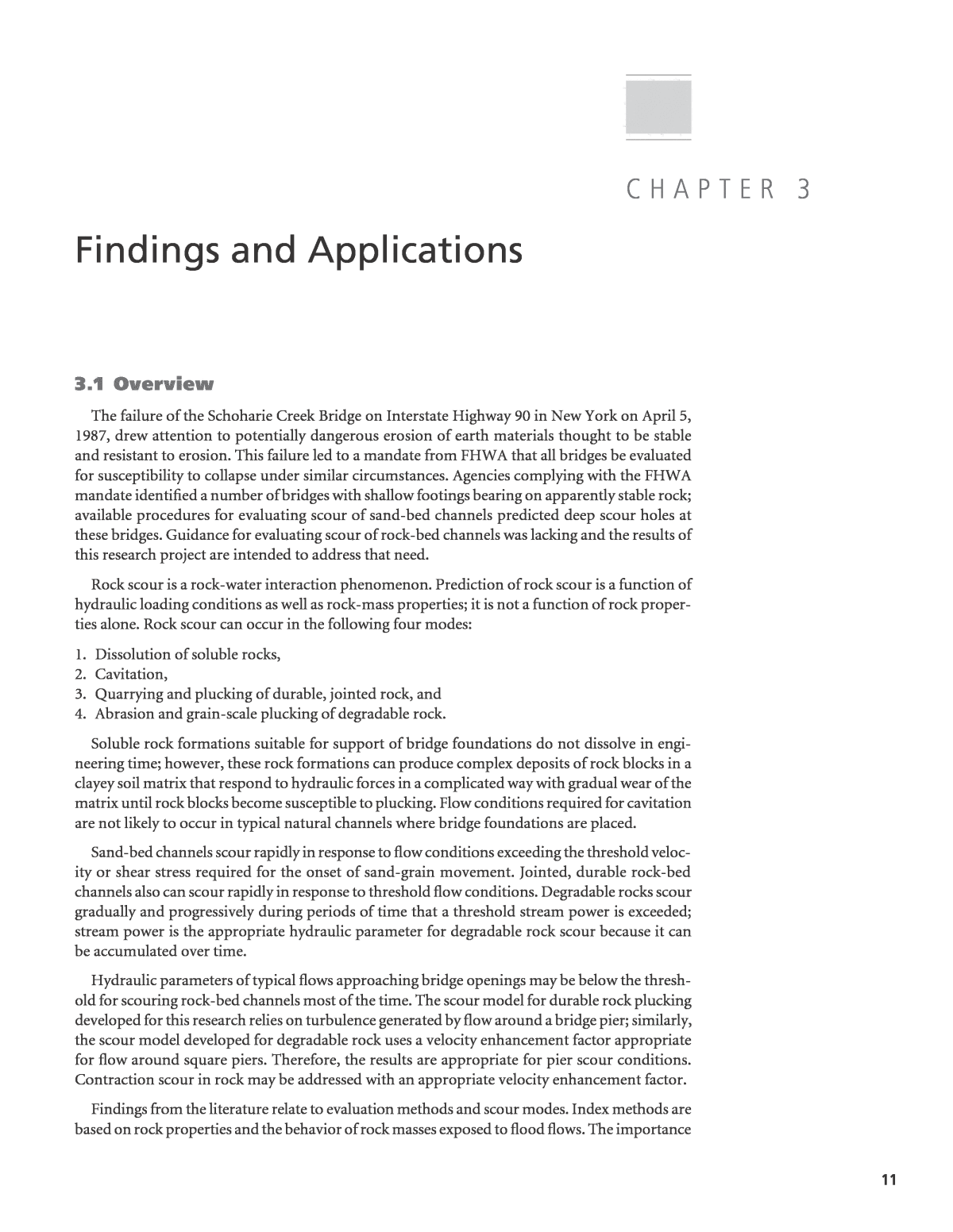
14 Scour at Bridge Foundations on rock FHWA Memo HNG-31 notes that geologic studies have shown that even the hardest of rock can scour when exposed to moving water for geologic-scale periods of time. Investigation pro- cedures listed in the FHWA Memo are (1) subsurface investigation, (2) evaluation of geologic formations and discontinuities, (3) calculation of rock quality designation (RQD) from rock core samples, (4) determination of unconfined compressive strength, (5) determination of Slake Durability Index, (6) determination of soundness when exposed to sodium sulfate or magne- sium sulfate solutions, and (7) determination of Los Angeles Abrasion Test loss. Erosion of rock and rock-like materials was studied extensively for stability of unlined spillway channels of dams. The early studies by Moore (1991) and Moore et al. (1994) built on an understanding of the power required for excavation of earth materials described by Kirsten (1982, 1988), which was called the Rippability Index. Kirstenâs empirical approach correlated the generalized engineering properties of rock with the horsepower rating of equipment that could or could not excavate the material. Kirstenâs (1982, 1988) Rippability Index classifies earth materials on a continuous range from loose granular or soft cohesive soils through hard, massive rock. A particular type of spillway channel erosion condition was upstream or upslope of knickpoints called headcuts. These procedures, particularly Moore et al. (1994), provided the basis for the field procedures guide for the Headcut Erodibility Index in the National Engineering Handbook (NRCS, 2001). Turbulent energy dissipation of water flowing over a headcut was expressed in terms of hydraulic power for the Headcut Erodibility Index method. The Headcut Erodibility Index, Kh, represents a measure of the resistance of the earth material to erosion. The index is the product of index numbers for four components of earth materials. Kh Ms Kb Kd Js= Ã Ã Ã [ . ]3 1 where Ms = material strength number, Kb = block or particle size number, Kd = discontinuity shear strength number, and Js = relative ground structure number. Unconfined compressive strength is used for Ms without consideration of variability through- out the rock or earth mass. The mean block size of intact rock material is used for Kb, which is determined from the spacing of discontinuities within the rock mass or mean grain size for granular material (Barton et al., 1974). The shear strength of the discontinuities in the rock mass is used for Kd. It also represents shear strength in granular soils. The number Js reflects the ori- entation and shape of individual blocks as determined by the orientations of discontinuities with respect to direction of stream flow. Smith (1994) elaborated on the Headcut Erodibility Index and Annandale (1995) called it simply Erodibility Index, which is the name used in HEC-18. Annandale (2000) characterized the glacial till deposits that formed the foundation soils of the Schoharie Creek Bridge on Interstate Highway 90 using the Erodibility Index procedures and calculated the decrease in hydraulic power of the 1987 flood peak from its maximum value at the streambed down into the local scour hole around the bridge pier (Figure 3.1). He interpreted the maximum scour depth to be determined by the intersection of the available stream power curve and the earth-material resis- tance curve. Annandale (2000) used two ranges of unconfined compressive strength for the Ms value in calculating the Erodibility Index, resulting in two curves for the power required to erode the earth materials. The actual scour depth produced by the 1987 flood is indicated in Figure 3.1 and matches closely with the Erodibility Index estimation. Smith (1994) used an early version of Annandaleâs (1995) paper and emphasized that Annan- daleâs stream power was based on turbulence intensity at peak discharge, which resulted in pres- sure fluctuations that are the primary cause of erosion by flowing water. Smith (1994) referred to Bagnold (1966) for an expression of stream power as the rate of energy dissipation per unit area.
Findings and applications 15 P V= t [ . ]3 2 where t = shear stress and V = mean channel velocity. Annandale (1995) referred to Yang (1973) for an expression of the rate of energy dissipation per unit volume of water (Pw) in open channel flow and modified it for unit discharge (q) over a unit length of channel (L) as follows: Pw w q Sf L w q E= =g g D [ . ]3 3 where gw = unit weight of water and Sf = slope of energy grade line. Thus, the units of P are (lb/ ft2)Ã(ft/s) = ft-lb/s/ft2 (= W/m2 taking into account acceleration of gravity; note that the units of P reduce to lb/ft-s which are the units reported in HEC-RAS output), whereas the units of Pw are (lb/ft3)Ã(ft3/s/ft)Ã(ft/ft)Ã(ft) = ft-lb/s/ft (= W/m). An error appears to have been introduced into Annandaleâs (2000) paper regarding scour at the Interstate Highway 90 bridge across Schoharie Creek in New York because the units for stream power in the paper and in the key figure (Fig- ure 3.1) are those for P even though the equation given for stream power is Pw (Equation 3.3). Coleman et al. (2003) evaluated fluvial entrainment of protruding rock blocks and calculated energy dissipation that was one to two orders of magnitude less than the threshold in Annandale (1995) and recommended that the Erodibility Index Method should be modified to account for the effects of block protrusion into the flow. Annandale (2005) provided discussion of the Coleman et al. (2003) paper and noted that Annandale (1995) erroneously expressed the erosive capacity of water as power per unit width, whereas it should be power per unit area. Annandale (2005) noted that power per unit area was implied in his 1995 paper, but not stated explicitly. Annandale (2005) also stated that the stream power for the Erodibility Index Method was to be quantified at the point of application (i.e., at the stream bed with local turbulence effects). Coleman et al. (2005) provided Figure 3.1. Graph showing available stream power at peak of April 5, 1987, flood and erosion resistance of riprap and the glacial till foundation materials at the Schoharie Creek Bridge. Modified from Annandale (2000).
16 Scour at Bridge Foundations on rock closure to Annandaleâs (2005) discussion and included a comment that their results indicated that greater protrusions resulted in lower flow strength for entrainment of the block into the flow, but that Annandaleâs (1995) Erodibility Index Method did not account for protrusion. Annandale (2006) refers to Schlichting and Gersten (2000) for turbulence production in the near-bed region and its importance in calculating stream power. Annandale (2006) states that the principal factor causing scour by flowing water is fluctuating pressure caused by turbulence near the boundary of the channel. The turbulence-dominated stream power in the near-bed region, Pt, is shown by Annandale (2006) to be Pt = =  ï£ï£¬  t r t rt wu 7 853 3 4 3 2 . [ . ] where tt = turbulent shear stress at the channel boundary, u = average flow velocity, r = fluid density, and tw = average wall shear stress at the boundary. The acceleration of gravity in proper units must be applied when converting the results from W/m2 to ft-lb/s/ft2. The average wall shear stress is the conventional shear stress along a channel bed at the upstream side of a bridge pier (Annandale, 2009, personal communication). Thus, a conventional shear stress of 80 Pa (1.7 lb/ft2) and average flow velocity of 1 m/s (3.3 ft/s) produces conventional stream power, P, of 80 W/m2 (5.5 ft-lb/s/ft2), but turbulent stream power, Pt, of 177.7 W/m2 (12.2 ft-lb/s/ft2). The turbulent stream power in this example is higher by a factor of approximately 2.2 than non- turbulent or conventional stream power. Bridges founded on rock in Kentucky were rated for scour condition by Hopkins and Beckham (1999) using a scoring system that included the proximity of any scour evidence to the footing, the depths of any holes caused by construction or scour, the distance that a hole might extend under a footing (penetration distance), and the traffic exposure in terms of average annual daily traffic. This rating system is a risk-based system since it includes elements of the hazard (scour conditions) and exposure of traffic to the hazard. The footing conditions used in Hopkins and Beckhamâs (1999) rating system are shown in Figure 3.2. Froehlich et al. (1999) report that 366 Kentucky bridges have at least one pier founded on rock. Of these, the scour hazard is high for 8.5 percent, moderate for 12.1 percent, and low for 79.4 percent. Hopkins and Beckham (1999) reported that scour is controlled by rock properties, including rock type, spacing of discontinuities, abrasion resistance, and weathering rate. Highly fractured Figure 3.2. Definitions of construction depth (dc), scour depth (ds), and penetration distance (dp) for Kentucky bridges. Modified from Hopkins and Beckham (1999).
Findings and applications 17 rock masses and those easily weathered are more susceptible to scour than rock masses that are massive and durable. Mechanical and chemical weathering can degrade rock over time, increas- ing susceptibility to scour. The Oregon Department of Transportation has determined that a number of bridges are sup- ported by spread footings on potentially erodible rock material and that the rate of scour in most rock masses is much less than the rate observed in cohesionless soils (Dickenson and Baillie, 1999). They concluded that routine foundation inspections and maintenance can mitigate the risk of catastrophic undermining of bridge foundations in rock. They acknowledged that erosion of weak and jointed rock can lead to on-going expensive maintenance problems at bridge foot- ings and require frequent monitoring, channel modification, and footing protection. Dickenson and Baillie (1999) selected 11 bridges in the Coast Range Province of Oregon that show evidence of scour adjacent to bridge footings in weak, jointed, and weathered sedimentary rock formations. These rock units vary in geomechanical classification from weakly cemented soil to strong rock and provide adequate support for bridges in terms of bearing capacity for spread-footing foundations. Dickenson and Baillie (1999) recognized the challenge for the engi- neering geologists, foundation engineers, and hydraulics engineers charged with characterizing erodible rock formations and identifying potentially vulnerable bridges. Dickenson and Baillie (1999) selected bridge sites on the basis of evidence of erosion, avail- ability of continuous historical stream gage information, geologic conditions, and the nature of the bedrock exposures across channels. Rock units at these bridge sites varied from very soft siltstone to hard tuff. Their study of general scour excluded local scour and contraction scour and related average rate of scour across natural stream channels to geomechanical properties of the rock and the integrated stream power. They selected an empirical approach comparing calculated channel changes to the stream flows that occurred over a known time interval because they concluded that the rock scour phenomenon in natural channels was too complex to accu- rately reproduce in flume studies or numerical simulations. Key parameters identified by Dickenson and Baillie (1999) are listed in Table 3.1. They note that their results are limited to rock units in the Coast Range of Oregon, and they selected stream reaches where the channels were straight and unobstructed. The extent of scour was calculated from current and earlier channel surveys. Scour depths and rates were computed and labora- tory tests were performed on samples of rock to obtain relevant geotechnical index properties. Stream gage data were used to develop hydraulic parameters of the stream flows during the time intervals between the surveys. Dickenson and Baillie (1999) noted that short-term streambed changes have been classified as scour and fill, whereas long-term changes are called degradation and aggradation. They use the terms scour and degradation interchangeably and caution that erosive processes in weak rock can be significant over one extreme flood event or over decades of âaverageâ flow conditions. They evaluated long-term channel changes that may take place over the service life of a bridge. Table 3.1. Parameters influencing the rate of scour in rock. (Modified from Dickenson and Baillie, 1999.)
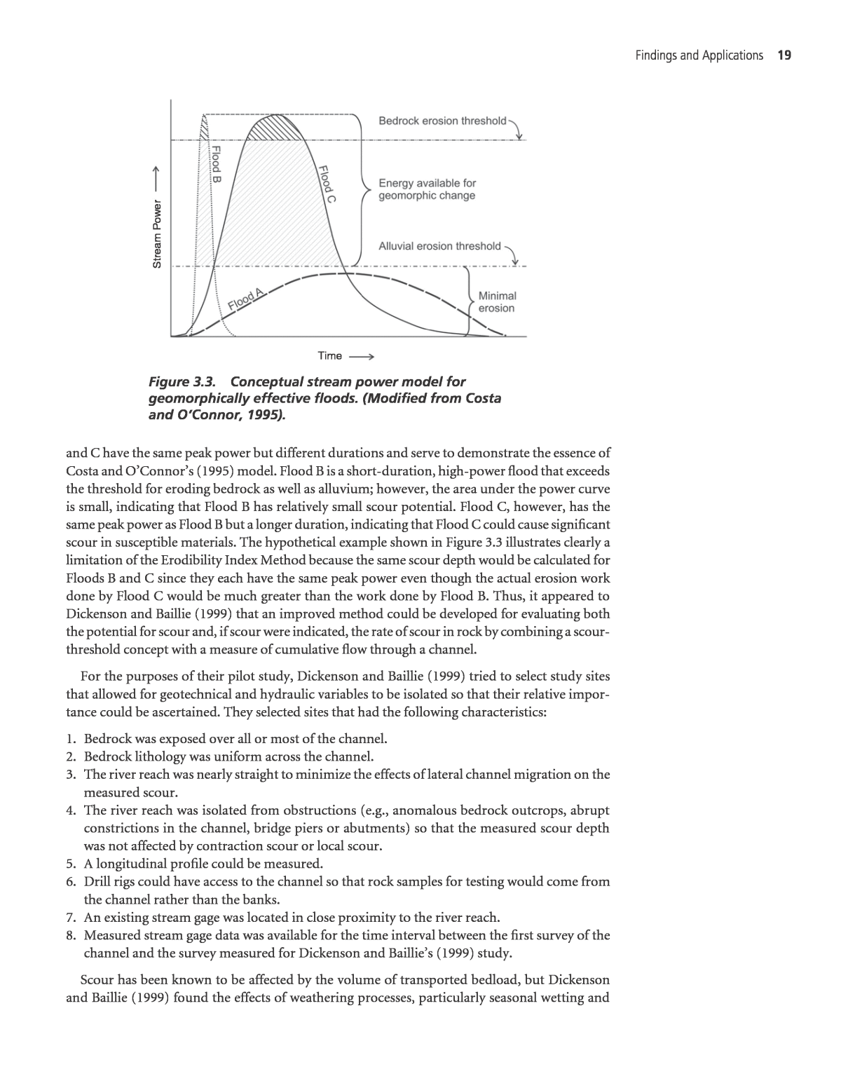
18 Scour at Bridge Foundations on rock Dickenson and Baillie (1999) refer to Akhmedov (1988) for defining three modes of rock ero- sion based on geologic response to hydrologic factors. Removal of rock fragments by hydraulic pressure gradients is Mode 1; rock discontinuities have the greatest influence on scour processes in this mode. Mode 2 is a shift to include abrasion to a greater degree than in Mode 1, in addition to removal of fragments by Mode 1 processes that increases the cross section area of the channel and reduces the mean velocity for constant discharge. Abrasion wears away at the rock mass, increasing the susceptibility to block removal. Once the flow energy is sufficiently low, Mode 3 abrasion is the only important process. The conditions studied by Dickenson and Baillie (1999) typically fall into Mode 3, but they note that conditions with very poor rock mass quality and higher stream gradients (slope > 0.6%) could experience Mode 2 processes during flood events. The Erodibility Index Method (Annandale, 1995) was considered by Dickenson and Baillie (1999). They noted that the method was developed for spillway channels and described three complicating factors for its use for estimating rock scour in natural streams. First, scour of a spillway is by clear water without bedload, so abrasion by bedload is not considered in the method. Second, hydraulic conditions in spillway channels with high rates of energy dissipation correspond most closely to Mode 1 scour processes, implying that channel degradation is by hydraulic jacking, dislodgment, and displacement of rock fragments and blocks (quarrying and plucking). Extrapolation of process response in spillway channels is required to lower energy lev- els typical in natural channels. Third, the Erodibility Index Method does not consider discharge duration or the rate of scour. The flow conditions in Oregon Coast Range streams differ from spillway channels in three important ways: (1) the streams carry bedload; (2) the bed slopes of streams are much gentler, resulting in substantially lower rates of energy dissipation; and (3) stream flow occurs peren- nially. Therefore, Oregon Coast Range streams are dominated by Akhmedovâs (1988) Mode 3 scour conditions when the stream power is too low to dislodge rock fragments or blocks, which occurs most of the time, and Dickenson and Baillie (1999) presumed that abrasion controls the rate of scour. The conditions in the streams evaluated by Dickenson and Baillie (1999) were consistently below the scour threshold indicated by the Erodibility Index Method, yet all of their study sites showed signs of bedrock erosion. Thus, they concluded that the Erodibility Index Method developed by Annandale (1995) needed to be enhanced to account for abrasion by the more-or-less continuous movement of water and bedload over the rock-bed channel. The stream discharge controls the bedload characteristics (sediment concentration and particle size). The cumulative effect of bedload on the rock-bed channel can be attributed to the hydraulics of the annual flow, assuming that the abrasiveness of the bedload is due solely to the kinetic energy of the moving particles. The influence of flow duration on the extent of scour studied by Costa and OâConnor (1995) was considered by Dickenson and Baillie (1999). Flood events that alter stream channels and overbank areas were called âgeomorphically effective floodsâ by Costa and OâConnor (1995). The Erodibility Index Method of Annandale (1995) considers only the peak flow conditions, and therefore the maximum rate of energy dissipation, as the available stream power in establishing a scour depth. In contrast, the effective flood method of Costa and OâConnor (1995) includes flood duration in calculating total stream power on the extent of channel degradation. The intensity of discharge and the flood duration are primary hydraulic variables in the effective flood method. The conceptual stream power model proposed by Costa and OâConnor (1995) is presented in Figure 3.3 for three hypothetical floods. Flood intensity is expressed as stream power in this model in a way which is comparable to the rate of energy dissipation developed by Annandale (1995). Flood A is a long-duration, low peak-power flood that would cause insignificant scour because it does not exceed the threshold condition to begin eroding alluvial deposits. Floods B
Findings and applications 19 and C have the same peak power but different durations and serve to demonstrate the essence of Costa and OâConnorâs (1995) model. Flood B is a short-duration, high-power flood that exceeds the threshold for eroding bedrock as well as alluvium; however, the area under the power curve is small, indicating that Flood B has relatively small scour potential. Flood C, however, has the same peak power as Flood B but a longer duration, indicating that Flood C could cause significant scour in susceptible materials. The hypothetical example shown in Figure 3.3 illustrates clearly a limitation of the Erodibility Index Method because the same scour depth would be calculated for Floods B and C since they each have the same peak power even though the actual erosion work done by Flood C would be much greater than the work done by Flood B. Thus, it appeared to Dickenson and Baillie (1999) that an improved method could be developed for evaluating both the potential for scour and, if scour were indicated, the rate of scour in rock by combining a scour- threshold concept with a measure of cumulative flow through a channel. For the purposes of their pilot study, Dickenson and Baillie (1999) tried to select study sites that allowed for geotechnical and hydraulic variables to be isolated so that their relative impor- tance could be ascertained. They selected sites that had the following characteristics: 1. Bedrock was exposed over all or most of the channel. 2. Bedrock lithology was uniform across the channel. 3. The river reach was nearly straight to minimize the effects of lateral channel migration on the measured scour. 4. The river reach was isolated from obstructions (e.g., anomalous bedrock outcrops, abrupt constrictions in the channel, bridge piers or abutments) so that the measured scour depth was not affected by contraction scour or local scour. 5. A longitudinal profile could be measured. 6. Drill rigs could have access to the channel so that rock samples for testing would come from the channel rather than the banks. 7. An existing stream gage was located in close proximity to the river reach. 8. Measured stream gage data was available for the time interval between the first survey of the channel and the survey measured for Dickenson and Baillieâs (1999) study. Scour has been known to be affected by the volume of transported bedload, but Dickenson and Baillie (1999) found the effects of weathering processes, particularly seasonal wetting and Time St re am P ow e r Figure 3.3. Conceptual stream power model for geomorphically effective floods. (Modified from Costa and OâConnor, 1995).
20 Scour at Bridge Foundations on rock drying, to have a significant influence on the amount of erosion along the stream channels. This effect was most pronounced in bedrock along stream banks that were submerged during wet-season months and exposed during dry months. Dickenson and Baillie (1999) observed bedrock recently exposed to air and noted that the surface started to crack and flake as it dried. The weakened, weathered rock was highly susceptible to erosion in the first flows the following dry season. The amount of rock that is eroded by this process depends on the thickness of the weathered zone. An independent study in north Texas by Allen et al. (2002) identified a similar slake-dominated zone in urban bedrock channels. Dickenson and Baillie (1999) drilled borings to obtain samples for laboratory testing and to characterize the geotechnical conditions of the rock. They tried to drill the borings in the stream- bed to avoid weathered rock or conditions not representative of the channel. They performed a suite of conventional geotechnical laboratory tests on representative samples to evaluate the strength and abrasion resistance of the rock. These tests included Los Angeles Abrasion (ASTM C131, 2006), Unconfined Compression (ASTM D7012, 2010), Density (ASTM D2937, 2010), and Slake Durability (ASTM D4644, 2008). They found that the ASTM Slake Durability Test was unrepresentative of local conditions for materials that do not have an opportunity to desiccate completely between wetting cycles. Dickenson and Baillie (1999) noted that the term âslake durabilityâ describes the behavior of samples that have been subjected to cycles of wetting and complete drying. Therefore, they devel- oped a modification to the ASTM standard procedure that excludes heated drying on the durability of the rock samples; therefore, the weight loss observed during their test reflects abrasion resistance, not loss caused by desiccation-induced slaking. They called this Modified Slake Durability Test a âcontinuous abrasionâ test to distinguish the behavior of the specimens tested to the behavior of similar rocks tested by the ASTM D4644 standard Slake Durability Test procedure. The continuous abrasion test shows an initially high rate that diminishes with time. The rela- tively high rate of weight loss at the start of the test is caused by angular rock fragments becom- ing sub-rounded to rounded. The fragments become well rounded and exhibit a much lower and typically uniform rate of weight loss after 120 to 200 minutes, which Dickenson and Baillie (1999) interpreted to represent the initiation of long-term abrasion loss. They plotted weight loss with time after 120 minutes in semi-natural log format and used the slope of the line as the basis for an index property they called the abrasion number. Larger abrasion number values are calculated for rock fragments that abrade quickly, whereas smaller abrasion number values indicate rock fragments whose edges do not chip easily and are more resistant to abrasion. Dickenson and Baillie (1999) performed continuous abrasion tests on 31 rock samples. They found abrasion numbers ranging from 1 to 10 for basalts and very hard rocks, from 10 to 20 for hard to weak sandstones, and from 20 to 30 or more for soft siltstones and shales. They found this test to be useful for identifying erodible rock material that would not have been classified as such using results from other geotechnical tests. As an example, they describe a particular sandstone formation as weak rock based on high core recovery and relatively high rock quality designation (RQD) values ranging from 70 to 100 percent. The sandstone had a compressive strength comparable to other sandstone units they investigated. However, the abrasion number value was between 20 and 25, indicating a relatively high abrasion rate and a potential suscep- tibility to scour. This example demonstrates that, although the sandstone would be suitable for support of bridge foundations (i.e., unconfined compressive strength â5800 psi or 40 MPa), it may be vulnerable to scour that could undermine a footing. The ASTM Slake Durability Test on some samples produced 100 percent loss by the second cycle, whereas only 60 percent loss was realized after 500 minutes of the continuous abrasion test; the sample had an abrasion number of 23.
Findings and applications 21 Dickenson and Baillie (1999) noted that the Slake Durability Test is not commonly used in standard geotechnical practice. Therefore, they evaluated possible correlations of the abrasion number to several standard rock properties that are used routinely. The abrasion number seems to correlate reasonably well with saturated bulk density of the rock, but only weakly with uncon- fined compression strength. The LA Abrasion test (ASTM C131, 2006) is used for determining the durability of gravel or crushed rock for use as aggregate in Portland cement concrete and asphalt concrete. Dicken- son and Baillie (1999) thought the test might be worthwhile for testing durability and hardness of competent rock, but the geologic formations in the Oregon Coast Ranges were too weak or soft for this test. Furthermore, a large sample volume is required for the LA Abrasion Test, mak- ing it impractical for formations with samples obtained only from core borings. Dickenson and Baillie (1999) also determined hydraulic parameters operating in the stream channels. They considered the hydraulic factors to represent the forces or demand on the bed- rock, while the geotechnical parameters represented the capacity of the rock to resist the erosive forces. The hydraulic factors control the magnitude of the forces acting on the rock at the base of the channel and include turbulence-induced uplift, bedload impact forces on the bedrock, and continuous abrasion by bedload. Dickenson and Baillie (1999) surveyed channel profiles and cross sections for use with the results of hydraulic investigations that included (1) acquiring and synthesizing daily stream gage data, (2) modeling water surface profiles using the U.S. Army Corps of Engineers HEC- RAS program (USACE, 2008), and (3) developing annual flow and stream power curves. They used the concept of Costa and OâConnor (1995) in evaluating the rate of scour as a function of cumulative stream power acting on the channel. The rate of erosion is controlled by the volume and velocity of the bedload that translates over the channel bed, as well as the water velocity and turbulence adjacent to the bed, assuming that the geotechnical parameters are equal. They assumed that the hydraulic factors can be expressed as the intensity and duration of the discharge, or as the cumulative stream power. A primary objective of their hydraulic investigation was to develop time histories of stream power that spanned the time interval from the date of the first channel cross section to the date of their most recent survey. The slope of the stream channel was assumed to be equal to the slope of the energy grade line of the flow, a common assumption that they recognized may be in error. However, the slopes they used in their analyses were obtained from 7.5-minute topographic quadrangle maps for con- sistency among sites even though the slopes they measured in the field were different. They pre- pared cross sections at the appropriate elevations, estimated Manningâs roughness coefficient (n) for the channel and the overbank sections, and modeled highest and lowest flows. They calculated hydraulic variables such as stream power, shear, velocity, and Froude number for each stream section. Dickenson and Baillie (1999) computed the stream power for the entire width of the stream and a unit length of channel by converting mean daily stream flow data using a power-law regression relation for stream power as a function of discharge; both discharge and stream power (using Equation 3.2) values are calculated by USACE (2008) HEC-RAS v. 4.0.0 and previous ver- sions for channel cross section, channel slope, and water depth. Their objective was to develop an approach that was not overly cumbersome so they modeled relatively straight channel sec- tions using the most recent cross section with channel slope determined from the 7.5-minute quadrangle map and assumed that the energy gradient was equal to the channel slope. Dickenson and Baillie (1999) developed a straightforward procedure for estimating scour that is based on the scour resistance of the rock in the channel and the hydraulic parameters causing scour. Their procedure used the abrasion number to represent the abrasion resistance of the rock
22 Scour at Bridge Foundations on rock and the stream power of the flow to represent hydraulic turbulence and uplift forces on rock particles, as well as the effects of bedload translating and saltating over the rock-bed channel. They computed the cumulative or integrated stream power that was expended during the time interval between the initial and final cross section surveys, which was the basis for estimating the average amount of erosion that occurred across the cross section. The results of Dickenson and Baillieâs (1999) procedure are illustrated in Figure 3.4. Their predictive procedure is applied by calculating integrated stream power for the design life of the bridge, determining the abrasion number of the rock-bed channel material, and estimating the resulting average cumulative ero- sion. They caution that their relation is based on few data and is applicable only for the geologic and hydraulic conditions in the Coast Range Province of Western Oregon for general scour. They note that the rate of scour estimated as a function of stream power would allow for scour depth estimates based on probabilistic discharge data. An analysis of rock scour was conducted by Ocean Engineering Associates (OEA, 2001) for Interstate Highway 10 at the Chipola River Bridge in Jackson County, Florida. The bridge foun- dation materials are described as âlime rock,â but they were considered to be erodible without test results to demonstrate otherwise. OEA (2001) conducted a study to determine the rate of erosion of the lime rock caused by shear stresses created by anticipated flow in the Chipola River. OEA (2001) tested core samples of the lime rock from the channel bed in a specially developed device at the University of Florida called the Rotating Erosion Test Apparatus (RETA; Hender- son et al., 2000). This device holds a core sample in a fixed position inside a rotating, water-filled cylinder. The rotating outer part of the cylinder causes the water surrounding the fixed core sample to move, thereby simulating flowing water. The loss of mass of the core sample after 72 hours of cylinder rotation is recorded along with the hydraulic shear stress calculated from the rate of cylinder rotation. The loss of rock mass is converted to a linear âerosionâ distance using the bulk density of the rock material and the radius of the core sample; the erosion dis- tance is normalized to the duration of the test, producing an erosion estimate with dimensions of velocity, such as mm/hr or m/yr. OEA (2001) notes that use of RETA applies only to rock conditions in which the rock erodes on a grain-by-grain basis rather than as rock fragments over a continuous stratum or layer at the bridge site. If the rock stratum is fractured, the size of the fragments bounded by the fracture surfaces must be large enough that they will not be transported by the design flows. OEA (2001) Figure 3.4. Average cumulative erosion related to integrated stream power and abrasion number. Modified from Dickenson and Baillie (1999).
Findings and applications 23 advised that the type and condition of the rock formation should be obtained by a site inspection and examination of the boring logs and may require the use of divers to inspect the bed near the piers for existing bridges. OEA (2001) recommends the Erodibility Index Method be used if the rock fragments are likely to be eroded by quarrying and plucking caused by the design flows. OEA (2001) estimated total scour (contraction plus local) depths at the channel piers based on the test results and a statistical representation of stream flow calculated at 5-year intervals for the design life of the bridge. The statistical representation of stream flow introduced conserva- tism by increasing the number of 50- and 100-year flood flows. Four rock samples tested with RETA showed negligible erosion (<2.5E-11 m/s) for the range of anticipated shear stresses. The maximum scour depth estimated by OEA (2001) at the end of a 50-yr period was approximately 0.012 m (<0.05 ft). Sheppard et al. (2006) undertook research funded by the Florida Department of Transporta- tion with the long-term goals of (1) accumulating sufficient information to develop a general relation between rate-of-erosion and standard geotechnical test results to eliminate the need for testing of the more scour-resistant materials and (2) accurately predicting design scour depths using rate-of-erosion test results, stream flow data, and bridge foundation information. Their research included testing with a new rate of erosion device, testing cohesionless sediments, and modeling mixtures of cohesionless and cohesive sediments. The report by Sheppard et al. (2006) reviews the two testing devices used at the University of Florida for measuring rate of erosion. RETA is for testing rock and other materials that will hold together in an unsupported core. The Sediment Erosion Rate Flume (SERF) is for testing cohesive and cohesionless sediments. Both testing devices measure rate of erosion in terms of the shear stress exerted on the sample instead of the velocity of flow. Shear stress in RETA is calculated from the torque of the rotating cylinder, whereas shear stress in SERF is calculated from pressure drop across the sample in the flume measured by sensitive transducers. Shep- pard et al. (2006) note that the core sample tested in RETA measures erosion over a vertical interval of rock, assuming that the core is obtained from a conventional vertical boring. A vertical core sample may not be representative of fluvial erosion on a gently sloping rock-bed channel. A number of references pertinent to rock scour come from the geology and fluvial geomor- phology literature; of particular value is a book edited by Tinkler and Wohl (1998) entitled, Rivers over Rock: Fluvial Processes in Bedrock Channels, published by the American Geophysical Union. In general, the scientific geomorphology studies address erosion from a theoretical per- spective of drainage-basin-scale processes occurring over geologic time. A quantitative approach to characterizing bedrock channel systems was developed by Hancock et al. (1998). The elements of the landscape and fluvial processes contributing to rock erosion in this model include inputs from tectonic uplift and climate, with sediment and runoff coming from hillslopes. Knickpoints and waterfalls represent features of locally high energy dissipation. Other channel properties include time-varying discharge, flow depth, flow velocity, velocity of the transported sediment, channel slope, and energy gradient. Important rock properties are joint spacing, joint orientation, resistance, grain size, and weathering. Important properties of sediment in the stream system are size distribution, concentration, transport mechanism (sus- pended load and bedload), velocity, and travel path. All of these factors contribute to erosion processes of abrasion, quarrying, and cavitation. They note that chemical dissolution may be an active process in some channels. Hancock et al. (1998) define rock abrasion as a process in which material is removed from a rock surface through forcible impact by sediment entrained in the stream flow. The abrasion rate is controlled by the kinetic energy delivered by grains impacting with the surface and the
24 Scour at Bridge Foundations on rock susceptibility of the rock surface to erode. The bedload grain impacts produce fractures within mineral crystals and rock fragments, dislodge individual grains, or break off flakes and frag- ments from the rock surface. The grain velocity, grain diameter, and grain density determine the kinetic energy; the effectiveness of this kinetic energy on abrasion increases as grain impact angle relative to the bed increases toward vertical. The susceptibility of rock material to removal by abrasion is controlled primarily by density, hardness, and fracture-mechanical properties of the rock bed and of the impacting grains. Hancock et al. (1998) consider eolian abrasion to be analogous to fluvial abrasion and describe a simple abrasion erosion rate as being controlled by susceptibility, the mass concentration of a particular grain size, water flow velocity, and the rock- bed density. Hancock et al. (1998) point out that the rock abrasion rate is proportional to flow velocity to the fifth power. It is clear that abrasion rates are very sensitive to local flow conditions and the details of the flow hydrograph. High stream velocities and the largest rare flow events produce the largest instantaneous erosion rates. Hancock et al. (1998) note that abrasion rates are sensitive to the grain-scale microphysics. Particle velocity relative to the channel bed is more important than water flow velocity. For a moving particle to impact the channel bed, the particle must decouple from the flow, because the flow velocity approaches zero in the boundary layer at the bed. Therefore, entrained sedi- ment must have sufficient momentum to decouple from the flow, pass through the near-bed flow boundary layer, and impact the rock bed with a force that exceeds the resistance for ero- sion to occur. Hancock et al. (1998) point out that knowledge of the sediment concentration in the flow is insufficient for predicting abrasion loss. Suspended sediment particle trajectories are influenced by the response of water flowlines to the microtopography of the bed and tur- bulence. Particles of suspended sediment may be steered by the water around obstacles or be directed into obstacles obliquely depending on grain inertia. Increased sediment concentration in the flow may actually decrease the rate of erosion as sediment supply begins to protect the bed from impacts, as described by Sklar and Dietrich (1998). A threshold condition may have to be exceeded for erosion by abrasion to be initiated; kinetic energy in some abrasion formulations requires grains to exceed either a threshold velocity or a threshold diameter (e.g., Anderson, 1986; Foley, 1980). A threshold discharge or flow duration may have to be exceeded to expose a rock-bed channel that has been buried by sediment during low flow conditions. Hancock et al. (1998) report that the most actively abrading portions of rock-bed channels are where sculpted rock bedforms and potholes occur. These bedforms tend to originate where abrupt flow expansions on the downstream edges of bed protrusions promote flow recirculation zones that are associated with flow separation. Hancock et al. (1998) describe flow separation occurring where the boundary layer of a stream of viscous fluid detaches itself from the boundary in response to abrupt expansions or adverse pressure gradients, generating a free-shear layer with a region of separated flow. These flow separation regions, which are characterized by high water flowline curvature, allow entrained sediment to decouple from the flow and impact the bed, as shown in Figure 3.5 with the flow path that has flow separation. This abrasion must be accom- plished by suspended grains because the erosional bedforms require that the grains be capable of delivering significant kinetic energy to the back sides of flow obstacles. Hancock et al. (1998) describe well-developed erosional forms, including flutes, on the tops of bedrock protrusions and on the crests of large boulders in the flow, particularly in fine-grained lithologies. The flutes commonly are symmetrical and overhanging on their upstream sides. The symmetry and overhanging character can be explained by vortices generated in the zone of flow separation developed at the ridge crests. Hancock et al. (1998) believe that high angular acceleration of the flow in the vortices is capable of flinging high-momentum suspended grains out of the vortices and against the bed with sufficient energy to etch sculpted forms that reflect the high-energy flow field.
Findings and applications 25 In addition to flow-separation vortices being generated by ridges in the rock-bed channel surface, they also can be generated by joints, fractures, and small bed irregularities. Flutes and potholes commonly are associated with these small irregularities. Once the flutes and potholes begin to form, their presence tends to further enhance the flow separation region. The flutes migrate in an upstream direction, like miniature knickpoints, indicating that erosion rates are highest on the upstream, overhanging ends of the forms, where recirculating flow is focused. Where the upstream progression of some flutes appears to stall, perhaps in response to reduc- tion in the strength of the flow separation, the flutes take on more rounded shapes and begin to behave like potholes, with downward focus of erosive energy from vertical vortices. Hancock et al. (1998) studied steep channels in hard, durable fine-grained igneous rock. It stands to reason that less durable rock and gentler channel slopes would produce smaller forms, possibly erod- ing rapidly enough for small-scale flutes to be generated and move across a bedrock protrusion without being recognized. Hydraulic quarrying is a common and efficient mechanism of lowering bedrock river channels where joint- and bedding-plane spacing and orientation allow it to operate; Whipple et al. (2000) suggest that plucking dominates in channels with rock that is well jointed on a sub-meter scale. Quarrying of bedrock blocks from the bed is accomplished by lifting or sliding of blocks bounded by existing discontinuities. Hancock et al. (1998) conclude that quarrying of blocks is the most rapid means of eroding a bedrock channel floor where the discontinuity spacing is sufficiently close to allow blocks to be moved by river flow. Their conclusion is based on the following two observations: 1. The channel bed morphology is blocky and defined by exposed joint or bedding planes that mark locations where blocks were removed, and 2. Abrasion flutes and potholes are shallow and minor features that do not appear to evolve quickly enough to modify the blocky channel topography before additional blocks are quar- ried or plucked from the channel bed. Hancock et al. (1998) developed two simple physical models of bed quarrying, one for lifting and one for sliding, to define flows that could quarry rock blocks from their intact positions. They anticipated that a period of time that they called âpreconditioningâ probably occurred before block removal so that the block was completely detached from the bed along the bound- ing discontinuities. The joint surfaces could be weathered, wedged apart, and/or weakened by bedload impacts during the preconditioning period. Block lifting would be generated by pres- sure differences in the flow, whereas block sliding or rotating would be generated by shear stress on the upper surface of a block that was unrestrained on its downstream side. Hancock et al. (1998) describe a previously undocumented process that tends to loosen rock blocks and prepare them for quarrying and plucking. The process they call hydraulic wedging Figure 3.5. Flow separation and entrained particle impact creating sculpted bedrock forms. Modified from Hancock et al. (1998).
26 Scour at Bridge Foundations on rock results in sediment particles accumulating in fractures and joints. They observed clasts ranging from fine sand to boulders wedged very tightly into bedrock joints. The clasts are wedged so tightly that hammer blows tends to shatter them before they come loose, implying that the clasts are either forced into the fractures or accumulate in a joint temporarily opened by turbulent flow conditions. Deposited sediment commonly is absent from the bed adjacent to the tightly filled joints, implying that the sediment is being transported efficiently across the rock-bed channels. Sediment trapped in the joints may enhance subaerial weathering of the rock adjacent to the joint surfaces, improve hydraulic connection to the bottoms of rock blocks, and contribute to other progressive preconditioning changes that make the rock blocks more susceptible to quar- rying and plucking. Hancock et al. (1998) note that cavitation occurs when local flow velocities are sufficiently high to produce small regions in the flow in which pressure temporarily falls below the vapor pressure of the water. Increased water velocities at local constrictions and obstructions may produce such regions, where water-vapor-filled cavities, or bubbles, then form within the flow. As the cavities move into regions of lower flow velocities with higher pressures, the cavities col- lapse producing powerful microjets of water that act as miniature high-energy water hammers causing pitting and cracking of solid surfaces. Hancock et al. (1998) used simplifying assump- tions to evaluate threshold mean velocities and channel slopes at which cavitation would be produced. They conclude that velocities and slopes where cavitation is likely occur only in locally steep or narrow reaches. They note that such locally steep reaches typically are associated with rapids that may aerate the flow, increasing the compressibility of the water and impeding cavitation. They suspect that cavitation in natural rock-bed channels is not a significant ero- sion process. They report looking for, but not finding, pitting or cracking of rock surfaces that could be caused by cavitation. The conclusion by Hancock et al. (1998) that cavitation is not a significant erosion process in natural channels also was reached by Baker and Costa (1987) who believe, based on catastrophic flood evidence including the Bonneville and Missoula floods, that channel adjustments produced by cavitation tend to inhibit or reduce the forces that would tend to cause the cavitation threshold condition between velocity and depth to be crossed. Whipple et al. (2000) suggest that cavitation may occur locally in vortices and contribute to sculpted rock channel forms. Tinkler and Parish (1998) monitored an urban rock-bed channel in the Toronto area of Ontario, Canada, for a year and documented that shale and thinly bedded limestone were weath- ered by chemical processes, freezing-thawing cycles, and wetting-drying cycles which made the slabby formation susceptible to quarrying and transport at flow magnitudes much less than the mean annual flood. Wetting and drying cycles appeared to have the greatest effect in preparing the formation for subsequent fluvial erosion. They measured erosion rates of about 0.07 ft/yr (2 cm/yr). Tinkler and Parish (1998) refer to Wolman and Gerson (1978) for support of the impor- tance of preconditioning in the rock erosion process stated by Hancock et al. (1998), as follows: It is worth emphasizing that âdown time,â hydrologically speaking, is not down time for the weathering processes affecting the channel bed, and so taking erodibility as an index, the amount of time between flow events, the relaxation time, may be expected to have a positive effect on the amount of erosion (Tinkler and Parish, 1998, p. 175). Tinkler and Parish (1998) realized that freshly deposited slabs immediately downstream of plunge pools below hydraulic drop structures were evidence of active quarrying and recognized the acceleration of water flowing over drop structures. They used the analysis of flume test results by Reinius (1986) to develop a relation for the threshold velocity required for quarry-
Findings and applications 27 ing slabs of varying thickness. Vertical joints provide more resistance to quarrying than joints inclined upward in a downstream direction (dipping upstream). Sklar and Dietrich (1998) subdivided zones of dominant process in drainage basins in terms of channel slope and drainage area. They found that drainage basins with average channel slopes greater than about 0.2 are dominated by debris-flow processes, rather than fluvial processes, whereas drainage basins with average channel slopes less than about 0.001 are dominated by fine-bed alluvial processes. Between these channel slopes, process domains are coarse-bed alluvial processes and bedrock-fluvial processes in drainage basins that range in size and steepness. Sklar and Dietrich (1998) note that the ratio of grain size to flow depth is greater than 1.0 for initial motion on slopes greater than about 0.08, and conventional fluvial hydraulics do not apply. The lower bound of the region where the stream power erosion law should apply corresponds to channel slopes that are low enough that the stream bed is covered with sediment too thick to be completely scoured. Sklar and Dietrich (1998) describe sediment supply as having two potentially opposite influ- ences on bedrock incision rates as follows: 1. The sediment supplies particles that impact with and abrade the bed, and 2. The sediment covers or allows the bedrock to be exposed to the erosive forces of the flow. They developed a quasi-mechanistic model to couple bedload sediment transport and abra- sion of bedrock. The model considers only erosion by saltating bedload and neglects the poten- tial for bedrock erosion by suspended load and other mechanisms, such as plucking, cavitation, and dissolution. They focus on abrasion because they believe that some sediment is transported in all bedrock channels and because the most concentrated momentum transfer from the flow to the bed is by particle impact. Sklar and Dietrich (1998) evaluated bedrock erosion rate as a function of sediment supply for different slope gradients. They concluded that the maximum erosion rate occurs at inter- mediate sediment supply and that the maximum efficiency of impacting particles occurs at intermediate slope. Too little sediment has few impacts with the rock-bed channel, whereas too much sediment provides a protective cushion for the rock-bed channel. Flat slopes have little transport capacity, whereas steep slopes have an inefficient impact angle for the saltating bedload particles. Laboratory testing for rock scour or rock durability has included several conventional tests and some specialized tests. Specialized tests are the jar slake (Santi, 2006), continuous abra- sion (Dickenson and Baillie, 1999), RETA (Sheppard et al., 2006), and abrasion mill (Sklar and Dietrich, 2001, 2004). Flume devices designed for cohesive soils may have application for some very weak rock materials: SRICOS-EFA (Briaud et al., 2004a, 2004b) and SERF (Trammell, 2004; Sheppard et al., 2006). Conventional ASTM tests for unconfined compressive and tensile strength of rock, slake durability of rock, abrasion of aggregate, soundness of aggregate are as follows: ⢠D7012-04 Standard Test Method for Compressive Strength and Elastic Moduli of Intact Rock Core Specimens under Varying States of Stress and Temperatures; ⢠D3967-05 Standard Test Method for Splitting Tensile Strength of Intact Rock Core Specimens; ⢠D4644-04 Standard Test Method for Slake Durability of Shales and Similar Weak Rocks; ⢠C131-06 Standard Test Method for Resistance to Degradation of Small-Size Coarse Aggregate by Abrasion and Impact in the Los Angeles Machine; and ⢠C88-05 Standard Test Method for Soundness of Aggregates by Use of Sodium Sulfate or Magnesium Sulfate.
28 Scour at Bridge Foundations on rock 3.3 Findings from Survey of State and Federal Agencies Four areas of inquiry were identified for the survey of state and federal agencies: 1. Determine the various practices used for estimating the extent and depth of bridge founda- tion scour in rock; 2. Identify bridges experiencing significant scour in rock. Select sites suitable for further inves- tigation in Phase II based on the availability of relevant data (e.g., time rate, scour history, hydraulic data, geotechnical properties, and pier configuration) for these bridges; 3. Determine geotechnical site-investigation sampling and testing protocols used to ensure an accurate assessment of rock characteristics; and 4. Determine best practices currently used for construction that minimize the potential for scour in rock. The survey was approached by formulating meaningful questions and compiling a list of appropriate individuals to contact at each state DOT and at the FHWA Federal Lands Highway Division Office. The questionnaire was kept short so that the length of time required to complete it would not be a disincentive to agency personnel in providing answers. A single questionnaire was used for both (1) geologists and geotechnical engineers and (2) hydraulic engineers and design and construction engineers. A commercial online survey utility was used for ease of administering the questionnaire; e-mail messages were sent to key groups and individuals that contained the URL link to the questionnaire. The questionnaire prepared to survey transportation agencies was formatted using a com- mercial online survey utility provided by Survey Monkey (http://www.surveymonkey.com/). The questionnaire was completed in time for distribution at appropriate committees at the TRB annual meeting in January 2007. Key members of the Highway Geology Symposium Steering Committee, many of whom are state DOT or FHWA employees, were contacted with the link to the questionnaire. Selected individuals in applied geology sections at state geological surveys were approached with general questions about erosion of rock channels. The individuals con- tacted typically were not aware of erosion problems in bedrock channels. The online question- naire remained active until mid-June 2007. A total of 45 responses were posted. Appendix B contains (1) the questionnaire as it was available online at SurveyMonkey.com, (2) graphic sum- maries of the responses, and (3) the comment fields from all 45 respondents. The questions are reproduced below, along with a summary of the statistical aspects of the responses, an overview of responses, and a listing of the actual comments in the same order for each question. Question 1. What is your general location? Of the responses, 42 provided state (including District of Columbia); 35 provided city/region; 18 provided additional comments; 3 skipped the question. State 1 Maryland 2 Kansas 3 Missouri 4 5 6 New York 7 Oklahoma 8 Hawaii 9 Florida 10 North Dakota 11 South Dakota 12 All states east of the MS River including states immediately west of MS River, Virgin Islands and Puerto Rico. 13 Nevada 14 DC 15 Colorado 16 New Mexico 17 California 18 California 19 Texas 20 Maryland 21 Minnesota 22 15-state region, west U.S. 23 Tennessee 24 California 25 California 26 Oregon 27 Pennsylvania 28 South Carolina 29 30 Connecticut
Findings and applications 29 36 Utah 37 Connecticut 38 California 39 New Jersey 40 Ohio 31 California 32 California 33 California 34 Vermont 35 Virginia 41 Florida 42 Iowa 43 Maryland 44 Mississippi 45 North Carolina Question 2: Does the inventory of bridges in your area identify if the foundation is soil or rock? Of the responses, 10 answered yes; 8 answered no; 3 answered not sure; 23 provided qualified answers; 1 skipped the question. The qualified answers follow. In general, the responses indicate that this information probably is available for newer bridges (less than 50 years old), including 285 bridges in Oregon founded on non-erodible rock, but may be available for few older bridges. 1 Foundation materials are outside of the scope of Marylandâs published Bridge Inventory. A file of as-built plans is maintained, which would include this information along with boring data. 2 3 4 5 6 7 8 Rely on soil borings on as-built construction plans to determine if foundation is on solid rock or on soil. Often times, visual inspection is sufficient, especially if the foundation is on solid rock. 9 10 11 12 Most often, yes. 13 14 FHWA employee. 15 We do not have an inventory of bridges. But one may be kept by our individual âclients,â including the National Park Service, National Forest, and Refuge Road Program. 16 17 Our database does not, but sometimes the information is available in Geology records, Foun- dation Plans, etc., if you look for it. 18 19 Our Bridge Database does not identify founding strata. However we have complete plans on most on-system (state owned) structures. Plans are available for only a portion of our off- system (locally owned) structures. 20 We have all bridge plans in an electronic database and most of the newer bridges have soils/ rock information. We have a long-term program to obtain soils/rock information on all spread footings where the current foundation material is unknown. 21 22 Bridge inventories generally describe foundations, though most of our work is new bridge construction, requiring investigation. 23 We have an R code in item 113B that indicates foundations on rock. Other coding for abut- ment and piers on rock as well. 24 25 New Bridgesâyes. Older bridgesânot necessarily. 26 NBIS does not. Oregon-specific scour database identifies 285 with spread footings on non- erodible rock.
30 Scour at Bridge Foundations on rock 27 Yes, but data is not available for many older bridges. Those with unknown foundations are treated as on soil. 28 29 We do not maintain foundation information in our National Bridge Inventory database. We have a separate seismic database in which AASHTO soil types (I, II, III, IV) are recorded from boring logs. If the presence of bedrock is relevant to the scour-critical determination, our hydraulic files would include an explanation of its relevance. 30 Yes, however not done on a consistent basis in a database field that can be easily searched. 31 Usually not, but occasionally mentions placing the footings on rock. 32 No. However bridge archives include Logs of Test Borings which identify the type of founda- tion material. 33 Sometimes. 34 Older bridges may not have that information. Bridges constructed in the past 50 years should have detailed information on foundation type. 35 36 Most of the time soil data sheets are part of the as-built drawing, therefore information is available. 37 Yes, however, not done on a consistent basis in a database field that can be easily searched. 38 39 40 41 My understanding is that you would deduce this information from the foundation type shown on the plans or in the inventory data sheet. 42 43 SHA bridge plans are available in an electronic file data base. For newer bridges, borings are included on the plans. 44 45 Question 3: If your organization manages bridges on rock foundations, how many do you have? Of the responses, 1 answered less than 5; 2 answered 6 to 10; 26 answered more than 10; 12 provided qualified answers; 4 skipped the question. The qualified answers follow. In general, the responses indicate that thousands (sometimes tens of thousands) of bridges in many states are founded on rock. 1 About 60 percent of our structures are founded on rock. We have limestone, shales, sand- stones, rhyolites, schists, gneiss, basalt, amphibolites, and quite a bit of saprolite. In MD, the state and county systems are separate. 2 Almost all of our bridges are founded in rock. The number is in excess of 1,000. 3 4 5 6 7 8 9 OEA is a consulting firm that does not manage bridges. 10 11 12 13 14 15 We have designed bridges on rock foundations, but we donât manage the operations and maintenance of the bridges.
Findings and applications 31 16 17 18 Not sure how many CT has now. 19 20 21 22 We build bridges for forest highway partners, but do not manage bridges directly. 23 The TN bridge database has 16,894 bridges over water; 6,554 bridges have at least 1 substruc- ture founded on rock; 2,384 bridges have rock under all substructures. The rest are not on rock or undetermined for coding. 24 25 26 27 About 6,000 as an unofficial number. 28 29 Not sure. This information is not maintained through my office, if at all. 30 31 32 33 34 35 Thousands. 36 37 38 39 40 Not exactly sure what is meant by âmanages,â we build bridges on shallow rock foundations, then we maintain them. 41 We do not have this responsibility. 42 43 44 45 Question 4: If your organization manages bridges founded on rock, what types of founda- tions are used? Of the responses, 7 answered spread footings; 3 answered drilled shafts; 31 pro- vided qualified answers; 4 skipped the question. The qualified answers follow. In general, the responses indicate that bridge foundations are spread footings, rock-socketed spread footings and drilled shafts, driven piles, micro piles, and end bearing piles. 1 Spread footings, lots of driven H piles, some drilled shafts, and a few pipe/mini piles. 2 Spread footings, drilled shafts as well as pile driven into bedrock. 3 4 5 6 Spread footings on rock and rock-socketed drilled shafts. 7 Usually spread footings, but we are replacing with drilled shafts. 8 9 10 11 Both spread footings and drilled shafts have been used. 12 Both drilled shafts and spread footings socketed into rock.
32 Scour at Bridge Foundations on rock 13 Both spread footings on rock and drilled shafts socketed into rock have been used. 14 15 16 Both spread footings and drilled shafts. 17 Both. 18 Old bridges tend to be spread footings on rock and new bridges drilled shafts (sometimes spread footingsâbut less often). 19 Most structures are on drilled shafts. Some older structures are on footings. 20 Both spread footings and drilled shafts are used. 21 22 In order of use: driven/drilled piles, drilled shafts, micropiles, spread footings. 23 TN has bridges on spread footings, drilled shafts, and point bearing piles. 24 25 26 27 Both with a few pedestals also. 28 Both spread footings and drilled shafts. 29 Not sure. This information is not maintained through my office, if at all. 30 Spread footings, drilled shafts, end bearing piles. 31 Normally spread footings, but occasionally piles driven into bedrock. 32 All types of foundations; spread footings, drilled shafts, and including different types of driven piles that are driven into decomposed and very soft rocks (end bearing). 33 Depends on age. 34 Depends on depth to rock. Spread footings, drilled shafts or piles may be used. 35 Spread footings, piles, and shafts. 36 Both spread and drilled shafts are used. 37 Spread footings, drilled shafts and micropiles drilled into rock, driven end bearing piles. 38 Generally Iâm referring abutments and toes of a concrete dam or concrete spillways that have been placed on a bedrock surface. The latter are often anchored by dowels into bedrock. The former are embedded and sometimes evaluated for overpour scour. 39 Shallow foundation (spread footings) and deep foundations (piles, drilled shafts). 40 Spread footings on shallow competent rock and drilled shafts when rock is deeper. 41 We do not manage bridges, but the majority of those founded on rock in this area are sup- ported by drilled shafts. 42 43 Spread footings, drilled shafts, driven piles and micro piles. 44 45 We use both drilled shafts and spread footings. Question 5: Does your organization evaluate erodibility of rock on which bridges are founded as part of evaluating scour criticality? Of the responses, 8 answered not at all; 6 answered a little; 4 answered moderate; 4 answered quite a bit; 2 answered extensive; 19 pro- vided qualified answers; 2 skipped the question. The qualified answers follow. In general, the responses indicate that no formal procedures exist for evaluating scour criticality related to erod- ibility of the rock on which bridges are founded. Some responses suggest that rock determined to be erodible is treated as soil for scour calculations. Other responses suggest that opinions of geotechnical or geology divisions are considered final in evaluating erodibility of rock. It is clear that current practices typically do not include evaluating scourability of erodible rock. Annandaleâs method has been considered in some cases. 1 Scour issues are evaluated by the Bridge Hydraulics Division with technical support from the Engineering Geology Division. Every new structure over water is evaluated. Older structures are evaluated when upgraded or when inspections indicate a need.
Findings and applications 33 2 We evaluate each structure for scour. 3 4 5 6 Based upon an evaluation of rock cores, including RQD, and exposed bedrock at the bridge site, we estimate the scourability of the rock on a scale of 1 to 10. This scourability score determines whether the footing should be keyed into rock for scour protection and by how much. 7 We had many approaches through the years. The Priority 1 scour inspections included bridges on spread footing embedded in potentially erodible rock with ADT > 150. Those were completed before I started working here (15 years ago). I donât know how they deter- mined how it was potentially erodible. Iâll ask around. 8 9 10 11 12 We would only evaluate scour if Geotech office determines rock to be âerodible.â 13 This has not formally been done to date. However, we intend to evaluate the rock on which some âscour criticalâ bridges are founded in order to verify or modify the current scour critical rating. 14 HIBT-20 wrote memo on scourability of rock in general use. 15 16 17 18 19 20 The Office of Bridge Development works with the geologists in evaluating the quality of rock cores. We have had limited experience in using George Annandaleâs Erodibility Index Method for rock foundations. In particular, we used the method to advantage in the design of the Woodrow Wilson Bridge to evaluate soils. 21 22 Geotech provides information on rock types/quality, but provides no information on erod- ibility. Hydraulics does not consider erosion for rock in scour calculations. 23 24 Our Geotechnical Support Office provides reports analyzing the rock types and recommen- dations if the bridge would be scour critical or not. 25 26 New bridges have extensive geotechnical reports. Old bridges may or may not have informa- tion on foundations. 27 Rock in Pennsylvania is rarely found to be erodible in the life of the bridge. In the few instances where it is an issue, it is treated as soil. 28 Geotech engineer makes the decision if rock is erodible or not. 29 The question of rock erodibility would be approached on a case-by-case basis. I am not aware of any formalized state (of Alaska) policy that addresses rock erodibility. 30 If the rock/foundation âinterfaceâ is exposed to stream flow, it would be considered, how- ever, most rock foundations are several feet below the stream bed surface. Several feet of scour would need to occur before rock is exposed. 31 32 33 34
34 Scour at Bridge Foundations on rock 35 36 37 If rock/foundation âinterfaceâ is continuously exposed to stream flow, it may be more of a consideration. Most rock foundations in CT are several feet below stream bed surface. Sev- eral feet of scour would need to occur to expose the rock to flow and potential for erosion to the rock. Given the nature of the rock in CT and time dependency of the process, erosion of the rock is unlikely to occur. In addition, we typically would not seat foundations on or in rock that would be susceptible to high rates of erosion (e.g., weathered rock). 38 Yes, as needed. 39 40 I am not sure what is being done regarding scour criticality evaluations. 41 Again, we do not manage the bridges, but we have never seen our clients account for the erodibility of rock. 42 43 44 45 Question 6: Is rock erosion or rock scour a problem in your area, particularly at bridge foundations? Of the responses, 7 answered not at all; 13 answered a little; 4 answered moder- ate; 1 answered quite a bit; 0 answered extensive; 18 provided qualified answers; 2 skipped the question. The qualified answers follow. In general, the responses indicate that rock scour is not considered to be a significant problem. Rock scour, if it is considered to be a problem, typically is considered on a case-by-case basis, rather than systematically. In few cases, rock scour may be considered significant. 1 Scour has been an issue on older bridges, especially those inherited into the system from other owners. We have little or no scour problems with newer bridges because the scour evaluation process is so very conservative, and our bridge designers (like most) are also very conservative. 2 This is a moderate problem for us. Our foundation material ranges from 900tsf limestone to less than 1 tsf shales. 3 4 5 6 7 Yes, we have red bed that when embedded is very strong, but when exposed to water or air is not, and we have cobbles that wash away. 8 9 10 Am not aware of any problems. 11 12 We cover a wide area. To us, rock scour is more an academic pursuit than something we seriously consider. 13 A littleâonly one or two bridges where undermining of spread footings on rock has been discovered. 14 15 16 17 Normally not, but a few cases have been problematic where we had high blow counts and yet the material was very scourable when wet. 18
Findings and applications 35 19 20 I am not aware of any general problem with rock. We have had concerns at individual bridges with coal seams, etc. 21 22 Unknown. We work over a 15-state region and build several bridges a year. I do not know of any follow-on work that has assessed the potential for this problem to occur. No rock- erosion-specific problems have come up in the last 10 years to my knowledge. 23 Only a problem if substructure is built on boulders, cobble, or weak or shaly bedrock. 24 25 26 There are 45 of the 285 that are considered to have a history of scour. Records are not spe- cific on whether foundation undermining or some other mechanism is attacking channel or embankments. 27 28 29 I am not aware of any rock scour problems. There are bridge sites in Alaska where bed- rock is exposed and may be susceptible to chemical weathering, freeze-thaw cycles, etc., and may as a result be susceptible channel incision due to bedload transport. Again, this would be addressed on a case-by-case basis and not through a systematic rock scour assessment. 30 31 32 California has a wide range of geological environment, and the rocks erode differently depending on the environment affecting them. Example: bridges founded on massive crys- talline rock will experience, will be more stable, than those founded on sandstone or shale. 33 34 35 Donât know, but assumed to be so for mudstone, claystone, siltstone, sandstone, shale, etc. 36 37 Not significant, if any. 38 39 40 Generally, our stream velocities are low so rock scour is not as much of a concern, but we do have numerous rock types including highly erodible weathered shales. 41 I am only aware of one instance in South Florida where Biscayne Bay is directly con- nected to the Atlantic Ocean through Hauloverâs Cut. We prepared retrofit plans to main- tain foundation stability. I would expect there are others around the state with similar problems. 42 43 Never lost a bridge to scour. Some minor scour experienced at a few sites. 44 45 Question 7: Does your organization have records of long-term scour of specific bridge foundations on rock? Of the responses, 23 answered not at all; 4 answered a little; 3 answered moderate; 1 answered quite a bit; 0 answered extensive; 10 provided qualified answers; 4 skipped the question. The qualified answers follow. In general, the responses indicate that only a few very specific bridges exist where long-term scour records have been maintained. 1 2 3
36 Scour at Bridge Foundations on rock 4 5 6 7 Some casesâthe two that come to mind have been replaced, but I know of others we are watching. 8 9 10 11 12 We keep detailed records not of scour depths, but of channel x-secs, taken every 3 years. 13 14 15 16 17 Sometimes cross sections or bridge inspections will note the amount of exposure of a foun- dation, which is a way of monitoring foundations on rock. 18 A few good examples: Mad River Route 299 (04-0036L/R), maybe Van Duzen River 04 0017L/R. 19 We have taken channel profiles for the past 10 years or so. We can compare those profiles to the channel profile shown on the original contract plans. 20 We have measurements of bridge inspectors for perhaps 10 to 20 years at most bridges. There are several old arch bridges on rock in Western Maryland that have been around for a long time. There has been an instance or two where some repairs were made where the rock had been eroded. 21 22 23 24 25 26 Some data either not accessible or difficult to recover. May not be reliable. 27 28 29 We maintain a record of bridge soundings at our bridges. Soundings are taken every 2 years during bridge inspections, and every year for scour-critical bridges. 30 31 32 33 34 35 36 37 38 We have file documentation (photos and notes) on jurisdictional dams going as far back as the late 1800s. 39 40 I only know of one bridge where we have monitored rock scour. 41 42 43 44 45
Findings and applications 37 Question 8: Has your organization tried to evaluate scour of rock quantitatively? Of the responses, 17 answered never; 1 answered once; 7 answered a few times; 2 answered a number of times; 6 answered not sure; 9 provided qualified answers; 3 skipped the question. The qualified answers follow. In general, the responses indicate that a few organizations have tried to evaluate rock scour quantitatively. The responses mentioned Maryland Stateâs method, Erodibility Index Method by Annandale, and the method published by Dickenson and Baillie in Oregon. Most organizations evaluate rock scour on a qualitative basis only. 1 Not sure what you mean by âquantitatively.â Rock foundation materials are determined to be scourable or not scourable. Foundation designs in scourable rock are adjusted to deal with the condition. 2 3 4 5 6 7 8 9 10 11 12 13 14 15 16 17 18 19 20 As noted above, we have used the Erodibility Index a few times. 21 22 23 24 25 26 FHWA Publication SPR 382 âPredicting Scour in Weak Rock of the Oregon Coast Range,â is our only serious effort. 27 We looked into this about 15 years ago and did not find any reasonable tests. We finally concluded it was not much of an issue and did not pursue. 28 29 Not that I am aware of, though my predecessors may have. 30 31 32 33 34 35 No, but have begun to look at existing methodologies to do so. 36 37 Qualitative assessments only based on limited rock data. Have never tried to quantify depths or rates of scour in bedrock. 38 39
38 Scour at Bridge Foundations on rock 40 41 42 43 SHA has a process for evaluating scour in rock. 44 There is rock in the Tallahatta Formation. We have had bridge replacement projects in Montgomery County where this formation is prevalent, but no attempt at evaluating scour has been utilized other than engineering judgment with HEC-18. 45 Question 9: If your organization has evaluated scour of rock, what method was used? Of the responses, 6 answered HEC-18; 5 answered Annandaleâs method; 20 answered other; 14 skipped the question. The qualified answers follow. In general, the responses indicate that methods used to evaluate rock scour range from qualitative methods (including geologistâs opinion) to empirical methods (comparison of as-built plans to present conditions) to analytical methods (Annandaleâs method and HEC-18), to specialized laboratory and computer methods. 1 In cooperation with the University of MD, SHA has developed its own method, ABSCOUR. I understand that it is loosely based on the HEC-18. This method is available online at www. gishydro.umd.edu. 2 HEC-18 was used most often and we also had a local university work a slake durability study for scour. 3 4 5 6 Several times we have tried to compare the existing rock surface to that shown on the bridge record plans to determine how much the rock has eroded. We had limited success doing this. 7 8 N/A 9 OEA has developed a methodology for evaluating scour in non-cohesionless sediments (rock/clay). 10 Have not evaluated scour of rock. 11 12 N/A 13 Not applicable. 14 15 16 17 18 Opinions of geologists. 19 20 21 Qualitative, consider likelihood of scour based on rock type. 22 23 N/A 24 25 26 I think study used Annandaleâs method modified to local conditions. 27 28 Laboratory flume test on limestone. 29 Not sure. 30 31
Findings and applications 39 32 33 Both. 34 35 Annandaleâs is what we have only recently begun to look into. 36 37 FHWA memorandum âScourability of Rock Formations,â dated July 19, 1991 (HNG-31), and HEC-18. 38 39 40 41 N/A 42 Scour safe if spread footings are founded in: >4â²âof weathered or broken limestone; any depthâany limestone other than weathered or broken; >7â²âany shale other than hard (or very firm) shale; any depthâhard (or very firm) shale; > 10â²âvery firm glacial clay. 43 44 45 We usually do not evaluate scour of rock but we have the EFA device from Texas A&M to evaluate scour of soil. Question 10: If your organization has evaluated scour of rock, has time-rate-of-scour been considered? Of the responses, 4 answered yes; 21 answered no; 2 answered not sure; 9 provided qualified answers; 9 skipped the question. The qualified answers follow. In general, the responses indicate that time-rate of scour has not been considered. 1 Our evaluation method produces a yes or no answer. 2 3 4 5 6 7 8 N/A 9 10 No experience. 11 12 N/A 13 Not applicable. 14 15 16 17 18 19 20 Not to my knowledge. 21 22 23 N/A 24 25 26 Bridges over water have channel cross-section taken at the bridge opening on a 10-year rota- tion. Not always done. The older the bridge, the less likely the information exists. 27
40 Scour at Bridge Foundations on rock 28 29 30 31 32 33 34 35 36 37 38 39 40 41 N/A 42 43 44 45 Question 11: Do knickpoints or waterfalls exist near bridges in your area? Of the responses, 19 answered yes; 10 answered no; 4 answered not sure; 20 provided qualified answers; 6 skipped the question. The qualified answers follow. In general, the responses indicate that a number of examples of bridges near knickpoints or waterfalls exist in various parts of the country, but they are relatively rare. 1 These bridges are not specifically cataloged, but we are sure that this condition exists in Mary- land because of the presence of the fall line that marks the boundary between the Piedmont and the coastal plain. 2 We have several small waterfalls either up- or down-stream of our structures; we also have several dams near structures as well. 3 4 5 6 7 We have scour holes, drops, and knickpoints or headcuts some downstream; some have gone through, some in the process of going through. 8 I need to investigate further on the exact bridge sites. 9 10 11 12 We might have a few bridges near waterfalls, perhaps in the Great Smokies National Park. 13 14 15 16 NM 456, Bridge #6237 replacement. 17 I would need to investigate the specifics later. 18 19 A very few. 20 21 Rarely. 22 Scenic locations near bridges are not uncommon in the parks and forest systems in our region.
Findings and applications 41 23 Mountainous areas in East Tennessee can have small waterfalls near bridges and knickpoints from headcuts can be found near bridges in West Tennessee. 24 25 26 Not many to my knowledge. 27 28 29 I do not have specific information readily available, though we do have bridges with nearby waterfalls. 30 31 32 33 Occasionally. 34 Terrain dictates location of falls, which may occur in proximity to crossings. Transitional areas from mountainous to valley. 35 36 37 38 Often knickpoints associate with narrow canyons, which are sought for dam sites. 39 Bridges that are located over the Passaic River near the Paterson Falls. 40 Fairly rare, if any at all. 41 42 43 Western Marylandâparticularly Georgeâs Creek Valley. 44 SR 15, Kingâs Creek, South of New Albany, MS. 45 Question 12: If your organization has one or more bridges founded on rock, then . . . 12a. Do design and/or construction practices exist for geotechnical characterization of rock? Not at all A little Moderate Quite a bit Extensive Donât know Rating Average Response Count 5.1% (2) 7.7% (3) 17.9% (7) 20.5% (8) 30.8% (12) 17.9% (7) 3.78 39 12b. Do design and/or construction practices exist of evaluating scour in rock? Not at all A little Moderate Quite a bit Extensive Donât know Rating Average Response Count 28.9% (11) 26.3% (10) 10.5% (4) 13.2% (5) 7.9% (3) 13.2% (5) 2.36 38 12c. Is sediment transport considered in evaluating abrasion of rock? Not at all A little Moderate Quite a bit Extensive Donât know Rating Average Response Count 65.8% (25) 18.4% (7) 0% (0) 2.6% (1) 0% (0) 13.2% (5) 1.30 38 12d. Do design and/or construction practices exist for remedial treatment of eroding rock at bridge foundations? Not at all A little Moderate Quite a bit Extensive Donât know Rating Average Response Count 16.2% (6) 18.9% (7) 32.4% (12) 5.4% (2) 8.1% (3) 18.9% (7) 2.63 37
42 Scour at Bridge Foundations on rock 12e. Has geologic and/or geotechnical field data been collected at a bridge with an eroding rock foundation? Not at all A little Moderate Quite a bit Extensive Donât know Rating Average Response Count 37.8% (14) 18.9% (7) 16.2% (6) 5.4% (2) 0% (0) 21.6% (6) 1.86 37 12f. Has field and/or laboratory test data been developed for the foundation materials? Not at all A little Moderate Quite a bit Extensive Donât know Rating Average Response Count 28.9% (11) 21.1% (8) 15.8% (6) 2.6% (1) 7.9% (3) 23.7% (9) 2.21 38 12g. Would pertinent geotechnical information be available to the researchers of this NCHRP project? Not at all A little Moderate Quite a bit Extensive Donât know Rating Average Response Count 21.1% (8) 28.9% (11) 5.3% (2) 5.3% (2) 0% (0) 39.5% (15) 1.91 38 Answered question: 39; skipped question: 6. Question 13: Please describe locations where bridge foundations on rock seem to be hav- ing scour-related problems. Please describe bridge foundations on rock that clearly are NOT having problems. Please feel free to make any other comments or offer any suggestions. Of the responses, 33 answered this open-ended question; 12 skipped the question. The responses follow. 1 Scour problems are addressed as a high priority, so it is almost impossible to identify a struc- ture with long-term scour issues. 2 Most of our bridges with scour problems are in two categories: (1) Shallow depths to soft bedrock, (2) unknown foundation types in known erosional material. 3 4 5 6 We have many bridges founded on rock that have no scour concerns. We have a few bridge sites that have probably undergone minor rock erosion but none that would be considered significant. 7 10740(2006051706)06Love Co SH 32 Rock Creekâno problems; Love Co US 77 Clouds Branch Creek Contraction scour or degradation in rock; Delaware Co US 412 A spread foot- ing in rock, poured over 60 yards of concrete in a scour hole under the footing and didnât fill it. Bridge has been replaced. Osage Co SH 97 over Delaware Creek bridge closed and replaced after fell due to rock degradation. Leflore Co SH 144 over Little Rock Creek, 10â² drop directly downstream in a rock/cobble bed. I am describing off the top of my head from memory to get this in on time. We have tons of pictures and measurements. 8 None. 9 10 The NDDOT has a few bridges built on spread footings where sandstone was too close to the surface to get pile penetration. The last one was built over 30 years ago. The surface of the sandstone was removed to a firm layer. The calculated scour depths have been above the footings in most cases. 11 Specific data not readily available. 12 Contact our bridge inspection team leader for bridge information. Contact our geotechnical engineer for geotech info.
Findings and applications 43 13 Problem areas have typically been where spread footings have been founded on sedimen- tary rock types. Non-problem locations are those where we have socketed drilled shafts into competent rock. 14 15 16 Presently, no active work or investigations of foundations on rock with scour-related prob- lems. Not having problemsâdeep canyons in which the water flow does not affect or come near substructures. 17 Most foundations on rock donât have any problems with scour. It has been the opinion of our Geotech Support that some cemented materials and other erodible rock may wear away from abrasion and long-term degradation, but not from local scour events. 18 There was a good bridge a few years ago (6-8), which was up north. I believe the remediation was a spread footer on rock. I want to say Klamath River (02 0117 comes to mind but I am not sure). The bridge dropped a bit (1 ft?)âthey jacked up the bridge and then retrofitted the pier and I think put some monitoring devices on the bridge. Take a look at 04 0036L/R alsoâthat was scoured rock. Person who did the earthquake retrofit design is quite knowl- edgeable. Good luck. 19 We have thousands of bridges on rock. The vast majority have no problems. We have a few that have exhibited some minor erosion/scour. 20 21 One interesting case is the Stone Arch Bridge located downstream from St Anthony Falls, over the Mississippi River. Bridge is over 100 years old (historic bridge was a RR bridge and has been converted to a pedestrian and bike bridge), originally spread on rock (sandstone, non-homogeneous with friable areas) foundations. Undermining was fixed structurally once and large riprap protection was added more recently. We have bridges on granite and other scour resistant rock that do not have scour-related problems. 22 23 These questions were answered with footings founded on solid rock in mind as opposed to boulders, cobble, or weak or shaly rock. Bridges founded on these other materials have problems but may not necessarily be scour in the classic definition. 24 So far, I have not encountered any problems with bridge foundations on rock. 25 Sediment rocks appear to be more of a concern. Their quality (density, hardness) seems to be in a wide range. In general, various bridges in east Shasta County founded on soft rocks give concern. Various bridges in Santa Cruz County along Highway 9âsandstones of poor and varying quality have scour holes or exposed foundations that should not be there according to as-built plans. Salmon Creek in Humboldt, 04C55, was recently field reviewed with inconclusive results. The shale rock found in the channel appeared hard in some places and then soft and fractured in others. We were unable to get any useful information at the concerned pier due to the amount of water and debris. Therefore, the bridge remains with a 113 code of a U for now. It appears the Coastal Range gives us more of a problem than those found in the Sierra Nevada Range. Igneous and metamorphic rock appears in general to be a good foundation material (if not weathered or fractured). Any time we come upon fractured or weathered rock, it warrants a field review and possible difficult assessment. 26 The FHWA report states other bridges that were considered for research. The original researchers may still be at OSU. Donât know for sure. 27 Specific information is available through our district offices and can be made available upon request. 28 29 Again, I am not aware of a specific rock-scour-related problem. Here in Juneau, a bridge comes to mind (Lawson Creek) but its (rock) foundation problem has more to do with rock
44 Scour at Bridge Foundations on rock type and weathering issues than rock scour. For bridge foundations on rock WITHOUT problems, I would direct you to the statewide foundation engineer. 30 31 The vast majority of the bedrock foundations are on fresh, hard bedrock by design and are not subject to undermining as a result. However, there are some cases where the foundation materials can be eroded under the right conditions. An example of this is Salsipuedes Creek on Route 1 in Santa Barbara County. The bents are founded on a bedrock that is fairly resis- tant to local scour but has a tendency to slough away when the channel bed degrades. There was concern that a headcut would undermine the footings. A check dam was constructed to stop the headcut. 32 Do not have this information available. 33 34 Rock here is generally hard and competent. I am not aware of any problems at bridges founded on rock. 35 36 Montezuma Creek Bridge has had problems; I-84 over Weber River has had problems. 37 Not aware of any particular problems in Connecticut. 38 Lake Hodges, San Diego Co.âhistorical scour and potential scour during design flood. Big Tujunga Damârecent plunge pool margin stability and shotcrete issues from spillway dis- charge. Armoring to be replaced/anchored during retrofit. 39 No input. 40 Brown County, White Oak Creek. 41 Bakerâs Haulover Cut Bridge, Highway A1A, Miami, Florida. See previous comments. Flor- ida Keys Bridgesâ11 miles of precast segmental bridge supported by drilled shafts founded in rockâno apparent scour problems after 25 years of service. 42 If we have a problem, it appears in locations where our spread footings are founded in shale. 43 Georgeâs Creek in Western Marylandâsediments and coal measures. 44 I am unaware that we have problems where there is rock. Our Geotech Division or our Bridge Inspectors could probably give more detail and I could provide their numbers. 45 One or two bridges founded on spread footings on Yadkin River Basins and Durham Trias- sic Basins have shown some scour under part of the footing. In the early 1990s we started designing all of our bridges for scour, and most of the foundation types are drilled shafts. 3.4 Modes of Rock Scour Four erosion processes in natural rock-bed channels have been identified (Hancock et al., 1998; Wohl, 1999). These processes are dissolution of soluble rocks, cavitation, quarrying and plucking of fractured rocks, and abrasion of degradable rocks. Hancock et al. (1998) and Tinkler and Parish (1998) commented on the importance of the time between flood events that can prepare rock surfaces for subsequent scour. Whipple et al. (2000) concluded that plucking is the dominant mode of scour in rocks that are jointed pervasively on a scale that is typically less than about 3 feet (1 m). Loosening and removal of rock blocks is facilitated by processes of hydraulic wedging of bedload fragments into rock joints, impacts and abrasion by bedload fragments, and chemical and physical weathering between flood events. Abrasion of more massive rock material by sus- pended particles appears to be more important than abrasion by bedload fragments, according to Whipple et al. (2000). Whipple et al. (2000) also report that cavitation appears to be more common in natural stream channels than previously thought, although distinctive evidence of cavitation may not be preserved. An important distinction between scour of rock-bed channels and scour of sand-bed channels is that rock scour is cumulative and progressive, whereas sand-bed scour is transient. Scour holes
Findings and applications 45 in rock-bed channels accumulate on a flood-by-flood basis; if the scour holes are filled during the waning stages of floods, the filling material is sand with much less scour resistance than the rock-bed material. Scour of sand-bed channels creates holes that tend to be filled during waning flood stages with sand that is similar in its scour resistance to the sand that was removed to cre- ate the holes; in this regard, scour of sand-bed channels is neither cumulative nor progressive. Scour of cohesive soil probably has similarities to rock scour in the sense that it is cumulative and progressive. 3.4.1 Time between Floods The time between flood events allows physical and chemical weathering to prepare the rock surface for scour during subsequent floods. Physical weathering processes include freezing- thawing cycles, wetting-drying cycles, plant-root growth, and salt crystallization. Chemical weathering processes include the effects of hydrolysis, carbonic acid, and organic acids (humic and fulvic) in the transformation of mineral grains into oxides, salts, and clay minerals. Physical weathering promotes fracturing or disintegration of rock mass, whereas chemical weathering softens, weakens, and alters the rock material. Turbulence during floods can jostle block of intact rock resulting in temporary opening of joints so that fragments of bedload (sand grains and gravel particles) can become wedged (called hydraulic wedging by Hancock et al., 1998, and Whipple et al., 2000). The wedged grains and particles cause the joints to remain open following flood events more than they would have otherwise. The open joints allow improved circulation of water and air, enhanced establishment of roots, and possibly more effective freeze wedging to occur. Tinkler and Parish (1998) describe low-flow channel water that freezes on the rock bed and anchors to slabs so firmly that subsequent minor discharge events may be able to float the anchor ice and lift the attached rock slabs in a process that is effective in loosening the slabs for future entrainment into the flow of a more substantial discharge event. The time between flood events appears to be most important for the quarrying and plucking and the abrasion processes; it also may have some importance for the dissolution process. 3.4.2 Dissolution of Soluble Rocks Some rock types are soluble in water, particularly limestone, dolostone, gypsum, and salt. Limestone and dolostone dissolve relatively slowly and are strong enough to form caves and steep-sided sinkholes, whereas gypsum and salt (halite and sylvite) are much more soluble than limestone and dolostone, but typically are not sufficiently strong to support cave openings. Limestone and dolostone present different types of issues than do gypsum and halite. The weak- ness of gypsum and salt formations is easily recognized during foundation investigations for bridges, and no bridges should be founded in these rock types. Therefore, scour of these forma- tions should not adversely affect bridge foundations directly. Gypsum veins and zones within more durable rock types would be expected to dissolve locally, which could alter the boundary conditions, contributing to other scour processes, such as enhanced opportunity for quarrying because of lower shear strength along such joint surfaces. Limestone and dolostone in geologic settings where caves and sinkholes have formed, prob- ably over geologic time, present potential hazards to bridges from a foundation support stand- point, and geotechnical investigations in these regions typically are designed with an objective of detecting subsurface voids. If the scour potential associated with undetected subsurface voids can be dismissed because of its critical importance for vertical load bearing capacity of bridge foundations, then the scour concern in limestone and dolostone formations is limited to the potential for the void-filling collapse debris or sedimentary breccia to be present in the vicinity of bridge foundations. Figure 3.6 shows subsurface conditions at a location on the Tennessee
46 Scour at Bridge Foundations on rock River in western Kentucky near Paducah discovered during construction of the Kentucky Dam. The variable scour resistance of the limestone rubble and soil filling the collapsed solution cavity could be a scour issue, even though the solubility of the limestone formation, per se, might not be a concern during the service life of a bridge structure. The void-filling limestone rubble in a soil matrix was detected to a depth of about 185 feet (56 m) below the channel bed elevation and 220 feet (67 m) below normal river level. 3.4.3 Cavitation Cavitation occurs when velocity fluctuations in a flow induce pressure fluctuations that cause formation and implosion of vapor bubbles. The shock waves generated by implosions can weaken bedrock and pit the rock surface, a phenomenon common along the concrete spillways of some dams. Cavitation may occur at flow separations induced by joints, bedding planes, or other surface irregularities in bedrock (Wohl, 1999). Cavitation-induced erosion of sandstone bedrock produced 30-foot (10-m) deep pools in 1983 in the 41-foot- (12.5-m-) diameter Glen Canyon Dam spillway tunnels that were discharging as much as 31,800 ft3/s (900 m3/s) (Wohl, 1999). Cavitation-induced damage or erosion of bedrock in natural channels has not been docu- mented widely and probably is not a significant erosion process at typical bridge sites across natural channels. Whipple et al. (2000) believe that cavitation is more likely to occur in natural channels than previously thought, particularly locally at flutes and obstructions. However, the large-scale rock erosion possible in spillway tunnels is not likely in natural channels. Baker and Costa (1987) plotted mean velocity and mean depth of flood flows from selected historic and prehistoric events. They set the Froude number to 1.0 to define the mean flow veloc- ity separating subcritical and supercritical flow regimes and evaluated the threshold velocity and depth for cavitation using a relation developed by Barnes (1956) and used by Baker (1974), as follows: V g Dc = [ . ]3 5 V Dcav = +2 6 10 3 6. [ . ] where Vc is the mean velocity at supercritical flow, Vcav is the mean velocity at the threshold of cavitation, g is acceleration of gravity, and D is mean flow depth (in meters for Equation 3.6). These threshold relations are plotted in Figure 3.7; Baker and Costa (1987) present two tables Figure 3.6. Solution features in cherty limestone at Kentucky Dam, Paducah, Kentucky. Source: Modified from Burwell and Moneymaker (1950); âfair useâ permission granted by Geological Society of America.
Findings and applications 47 in their paper containing calculated and estimated flow parameters of these flood events from which the numbers in Figure 3.7 were obtained. Baker and Costa (1987) conclude that channel adjustments produced by cavitation tend to inhibit or reduce the forces that would cause the cavitation threshold to be crossed in nature. They state that few, if any, powerful natural flows barely exceed the conditions expressed in Equation 3.6. Hancock et al. (1998) considered cavitation in their study of a steep rock-bed channel of the Indus River in Pakistan. They evaluated threshold mean velocities and channel slopes using simplifying assumptions based on the Bernoulli equation and the Darcy-Weisbach equation for open-channel flow with Manningâs n value of 0.030. The Bernoulli equation is v g p g z v g p g zm a w s c v w b 2 2 2 2 3 7+ + = + + r r [ . ] This expression uses a mean flow velocity, vm, across the normal channel cross section and a local velocity at the point of cavitation, vc, which is k times higher than the mean velocity. The terms pa and pv are the atmospheric pressure and the vapor pressure of the water, respectively, and zs and zb are the elevations at the water surface and the channel bed, respectively. Hancock et al. (1998) set the threshold cavitation velocity, vc = kvm, and water depth, H = zs - zb, and solved Equation 3.7 for mean velocity as follows: v p p k gH k m a v w = -( ) -( ) + -( )     2 1 2 1 3 8 1 2 r [ . ] The Darcy-Weisbach equation for mean flow velocity, v, is v gS H f e =  ï£ï£¬   8 3 9 1 2 [ . ] with Manningâs n value and the continuity equation, Q = vHw, to relate Q to Se and H gives S n v H m = 2 2 4 3 3 10[ . ] where channel slope, S, is substituted for energy grade line slope, Se. Figure 3.7. Mean velocity and depth for cavitation in natural channels. Based on Baker and Costa (1987).
48 Scour at Bridge Foundations on rock Hancock et al. (1998) solved Equations 3.8 and 3.10 for pa = 101 kPa (sea level), pv = 1.23 kPa (for water at 10° C), k = 2 or 3, rw = 1.0, g = 9.807 m/s2, and Manningâs n = 0.030. Whipple et al. (2000) considered k = 4 to be the lower bound for the inception of cavitation. These relations are plotted in Figure 3.8 with cavitation likely for mean depth and velocity conditions above the velocity curve labeled âCavitation Factor = 2â (k = 2) and cavitation unlikely below the velocity curve labeled âCavitation Factor = 4â (k = 4). The cavitation factors are the same as the k parameter in Equation 3.8. Therefore, curves for cavitation factors of 2, 3, and 4 are plotted in Figure 3.8. For comparison, the critical velocity curve (Equation 3.5) is plotted in Figure 3.8, as well as in Figure 3.7. The velocity curve in Figure 3.8 labeled âCavitation Factor = 4â is nearly identical to the curve in Figure 3.7 labeled âCavitation Threshold.â These curves for Cavitation Factor = 4 and Cavitation Factor = 2 are not exactly linear, but nearly so; the linear approxima- tions for these curves are V D â +27 3 approximate threshold for possible cavitation( ) [ . ]3 11 V D â +47 5 2 . approximate threshold for likely cavitation( ) [ . ]3 12 Whipple et al. (2000) postulate fluvial conditions in which local velocities around obstruc- tions exceed the mean velocity by more than 70 percent (velocity enhancement > 1.7) and cavi- tation is induced down the cores of vortices. Hancock et al. (1998) suggest that cavitation in natural channels is rare and believe that the rock sculpting process is dominated by abrasion. Whipple et al. (2000) note that distinctive evidence of cavitation is not as associated with rock as it is with metallic surfaces; they further note that abrasion certainly contributes to flute and pothole erosion even if cavitation also occurs and subsequent abrasion action may eradicate cavitation evidence on rock surfaces. Turbulent flow in natural channels commonly is aerated to the point of being frothy in shallow flows. Frothy aeration inhibits cavitation by providing direct paths for dissipating pressures to the water surface. The presence of air in the turbulent water undoubtedly cushions the implosion Figure 3.8. Mean flow velocity, depth, and slope conditions where cavitation may be possible. Based on analyses by Hancock et al. (1998) and Whipple et al. (2000). Cavitation factor is vc / vm.
Findings and applications 49 of cavitation bubbles, which would inhibit development of cavitation for extended periods of scour. Whipple et al. (2000) point out that aeration can substantially reduce cavitation damage and has been used to mitigate cavitation in engineering structures. It is clear from Figures 3.7 and 3.8 that the mean flow depth and velocity required for cavita- tion is unlikely to occur in natural channels where bridge foundations would be constructed. Cavitation in natural channels would require steep, narrow chutes with high flow velocities and substantial flow depths; these channel conditions would be spanned by bridges so that foun- dations would be on opposite sides of the chutes, not within them. The mean flow depth and velocity conditions shown in Figures 3.7 and 3.8 can be used as a check for possible cavitation processes at sites of existing or proposed bridges based on simple hydraulic parameters that are needed for design. 3.4.4 Quarrying and Plucking of Durable Rocks Hancock et al. (1998) developed two simple physical models of rock-bed quarrying: one for block lifting and one for block sliding. They anticipated that a period of joint weathering or âpreconditioningâ probably was needed for blocks to become completely detached from the bed along bounding discontinuities. The joint surfaces could be weathered, wedged apart, and weak- ened by bedload impacts during the preconditioning period. Block lifting would be generated by pressure differences in the flow, whereas block sliding would be generated by shear stress applied on the upper surface of the block. Tinkler and Parish (1998) evaluated quarrying by applying flume test results from Reinius (1986) to develop a relation for the threshold velocity required for quarrying slabs of varying thickness. Procedures for evaluating general erosion of unlined spillway channels for dams described in the National Engineering Handbook (NRCS, 2001) include quarrying and plucking of rock blocks. Bollaert (2004), Bollaert and Schleiss (2003a, 2003b, 2005), and Annandale (2006, 2007) discuss rock scour by block removal, brittle fracture, and fatigue failure in high-energy impinging- jet pools below dam spillways. The NRCS (2001) method is called the Headcut Erodibility Index, whereas Annandaleâs (1995, 2006) procedure is called the Erodibility Index Method. The two methods are based on Kirsten (1982, 1988) and utilize the same parameters. Both methods are based on a threshold concept in which the channel bed remains stable until the hydraulic forces expressed as stream power at peak discharge exceed the resistance of the earth materials expressed in equivalent power terms. Once the erodibility threshold has been attained by the stream flow, the scour hole develops rapidly to its maximum extent in a manner analogous to scour of sand-bed channel response modeled by procedures described in HEC-18 (Richardson and Davis, 2001). Bollaertâs (2002, 2004) Comprehensive Scour Model was applied by Bollaert as part of this research project to quarrying and plucking of regularly shaped rock blocks near bridge pier foundations (Bollaert, 2010). The results are presented in Appendix C for numerical modeling of various hydrodynamic conditions appropriate for natural channels where bridge foundations might be located. The two-phase transient numerical model simulates the time evolution of quasi-steady and turbulent forces around a single, completely detached rock block and expresses the potential movements of the block as a function of the flow turbulence and the stream power in the scour hole that forms around a bridge pier. The hydraulic action on layers of identical rock blocks is automatically adapted numerically during scour-hole formation by assuming that the rock-block layer is removed once the single block is entrained into the flow. The model is one- dimensional because a single rock block is considered on a layer-by-layer approach. The model may be considered to have limited two-dimensional characteristics because fluctuating pressures are considered to act in joints on both sides of the single rock block. Rock-block entrainment is defined in this numerical model as block lifting equal to 20 percent of the block dimension
50 Scour at Bridge Foundations on rock perpendicular to the channel bed. Both the ultimate scour depth and the scour threshold flow velocity are determined as a function of (1) the shape, dimensions, and protrusion of the rock blocks, (2) the average upstream river bed slope, and (3) the dip angle of rock joints. The ulti- mate scour depth estimate is normalized to the bridge pier diameter so that it is dimensionless. The general model for rock quarrying and plucking is shown in Figure 3.9. The hydraulic parameters used in the durable-rock-plucking model consist of the approach stream power (Equation 3.2), turbulence-enhanced stream power (Equation 3.4), and factors for adjusting the turbulent stream power based on pier shape and angle of attack from HEC-18 (Tables 6.1 and 6.2 in Richardson and Davis, 2001). Fluctuating pressures caused by pier- induced turbulence were modeled as a simple sine curve with a frequency of 10 Hz and the assumption that the fluctuating pressure peak acts simultaneously in joints on both sides of a rock block. Four shapes of rock blocks were used in the numerical model. All blocks were regularly shaped and 1 meter (3.3 ft) long in the direction of flow and 1 meter (3.3 ft) wide. The blocks had vari- able height ranging from 0.25 meters (0.8 ft) to 2.0 meters (6.6 ft), as shown in Figure 3.10. The block height-to-length ratios were 1:4, 1:2, 1:1, and 2:1. The blocks had horizontal tops and bottoms modeled as parallel to the flow direction. The blocks had vertical sides parallel to flow and either vertical or inclined sides perpendicular to the flow direction dipping 30°. Friction along vertical joints was neglected in the numerical modeling, whereas a friction factor of 0.577 (= tan 30°) was included in the model for the inclined joints. The numerical model did not dif- ferentiate inclined joints relative to stream flow direction; hence, the numerical analysis results Figure 3.9. General model and hydrodynamic parameters at bridge piers founded on discontinuous blocks of rock. Note: Rock-bed channel condition at the pier before the block entrainment threshold is reached (left); channel condition at the pier after the scour-hole depth is equal to the pier diameter (right). Hydrodynamic parameters are described in Appendix C. Figure 3.10. Block shapes used in numerical model of hydraulic plucking. Note: Hb = block height in the vertical direction, Lb = block length in the direction of flow, and Wb = block width in the direction perpendicular to flow; Lb = Wb = 1 m (3.3 ft). Block-joints were vertical or dipping 30° (flow direction not modeled).
Findings and applications 51 are the same for rock blocks dipping with, or against, the flow. Rock specific gravity used in all cases was 2.65 (165 lb/ft3 or 2650 kg/m3 density). The upper surfaces of the rock blocks forming the stream channel were modeled as perfectly smooth or protruding into the flow by moderate (~ 5 cm) or large (⥠10 cm) amounts. The results of the numerical modeling are presented in Appendix C and summarized in Fig- ure 3.11 for threshold velocity for plucking. Figures 3.12a through 3.12d summarize depth of scour normalized to pier diameter (as based on results in Appendix C for vertical joints, no block protrusion, and four slope values). Much of the available research on quarrying and plucking of durable rock blocks has been done on steep, unlined spillways and in plunge pools below high-energy, impinging jets. Case histories were sought for calibrating Bollaertâs (2002, 2004) Comprehensive Scour Model for natural channels with slopes common to bridge site locations; however, no suitable cases were found. Therefore, to serve as a comparison, the Headcut Erodibility Index Method (NRCS, 2001) and the Erodibility Index Method (Smith, 1994; Annandale, 1995, 2006) were applied to the durable rock-block situation for shapes of 1:4 (block height: block length) and steep channel slopes of 0.1; this modeling case appeared to be useful for comparison because the rock blocks are thinnest and the slope is steepest. Durable rock was assumed to have unconfined compressive strength (UCS) of 36,260 psi (250 MPa) and a unit weight of 165 lb/ft3 (2650 kg/m3). The joints were assumed to be smooth, planar, and separated by 1 to 2 mm. The Headcut Erodibility Index Method is described in step-by-step procedures in the National Engineering Handbook, Part 628, Chapter 52, Appendix 52B (NRCS, 2001); the earth spillway erosion model described in Chapter 51 (NRCS, 1997) refers to Chapter 52 for the Headcut Erodibility Index Method. Chapter 52 refers to a spreadsheet for calculation of parameters in the Headcut Erodibility Index Method, including rock mass properties and the hydraulic Figure 3.11. Summary of threshold velocities for plucking rock blocks of various thicknesses. Based on results presented in Appendix C for vertical and inclined joints, two block protrusion conditions (none and large), and a range of slope values.
52 Scour at Bridge Foundations on rock Figure 3.12a. Summary of ultimate scour depth normalized to pier diameter for rock blocks of various thicknesses and flow velocity. Three-dimensional view based on results presented in Appendix C for vertical joints, no block protrusion, and four slope values. Figure 3.12b. Scour depth normalized to pier diameter as a function of block thickness. Based on results presented in Appendix C for vertical joints, no block protrusion, and four slope values.
Findings and applications 53 energy. The Headcut Erodibility Index Method spreadsheet is available online as a Microsoft Excel file on the NRCS website for hydraulics and hydrology tools and models at http://www. wsi.nrcs.usda.gov/products/w2q/H&H/Tools_Models/Sites.html. The spreadsheet file by itself is at http://www.wsi.nrcs.usda.gov/products/W2Q/H&H/docs/sites/khcalc.xls; both sites were accessed in December 2009. For convenience, Chapter 52 of the National Engineering Hand- book is reproduced as Appendix D, along with the Microsoft Excel spreadsheet referenced in it. Also for convenience, the Erodibility Index Method, along with necessary tables, is described in Appendix E. Figure 3.12d. Velocities and block thicknesses used in numerical modeling of scour depths. Based on results in Appendix C for vertical joints, no block protrusion, and four slope values. Figure 3.12c. Velocities associated with hydrodynamic conditions used in numerical modeling to calculate scour depths. Based on results in Appendix C for vertical joints, no block protrusion, and four slope values.
54 Scour at Bridge Foundations on rock The results of the comparative analysis of the two index methods are summarized in Table 3.2. A velocity enhancement factor of 1.7 times the approach velocity developed for design of riprap at rectangular piers (Lagasse et al., 2001b, p. DG8.4) was used with the Headcut Erodibility Index Method with the intention that turbulence in the water flow would be generated by a hypotheti- cal bridge pier. The rock mass properties used in the comparative analysis were estimated from the parameters used in the Comprehensive Scour Model described in Appendix C; therefore, the results of the Headcut Erodibility Index and Erodibility Index Methods should be comparable with the results of the Comprehensive Scour Model. The comparative analysis summarized in Table 3.2 shows several differences in the way the rock mass properties are used in calculating the Headcut Erodibility Index or the Erodibility Index. The Headcut Erodibility Index uses the unconfined compressive strength value as the material strength number (Ms) for UCS > 10 MPa, whereas the Erodibility Index Method uses the coefficient of relative density with a reference rock unit weight of 2,700 kg/m3 (168.5 lb/ft3). The block size number (Kb) in both methods differs only in rounding; the values from the Headcut Erodibility Index were taken from the spreadsheet available on the NRCS website. It should be noted that the rock blocks used in the numerical model have thicknesses of 0.25 meter. Therefore, a theoretical vertical core boring through the rock blocks would encounter no vertical joints and horizontal joints every 0.25 meter; therefore, the actual RQD would be 100 because the definition of RQD is based on intact rock pieces that are 0.1 m or more in length. The biggest difference between the Headcut Erodibility Index and the Erodibility Index Method in this example is with the discontinuity number (Kd). The Headcut Erodibility Index provides a table of joint alteration (Table 10 in Appendix D) that includes a value of Ja = 1.5 for clean joints open 1 to 5 mm, whereas the comparable table in the Erodibility Index Method (Annandale, 2006, Table 4.8) implies that unaltered joint walls open 1 to 5 mm have Ja = 1. Both methods use a joint roughness of 1 for smooth planar joints, resulting in Kd = 0.67 for the Headcut Erodibility Index and Kd = 1 for the Erodibility Index Method. Most of the difference in the values of the Headcut Erodibility Index and Erodibility Index Methods is caused by the 33 percent difference in the Ja value. The relative ground structure number, Js, used in Table 3.2, is the same for both methods, but it should be noted that the spreadsheet for the Headcut Erodibility Index Method calculates Js only for a ratio of joint spacing r = 1:1. The notes contained in the Headcut Erodibility spread- sheet referred to in NRCS (2001) in Column A below Row 59 do not indicate this limitation in the calculation of Js in Cell B15. Computation Box 8 of NRCS (2001) Appendix 52B presented in Appendix D includes a statement that the spreadsheet calculation is for a joint spacing ratio r = 1 (1:1). Therefore, the resulting value of the Headcut Erodibility Index in Table 3.2 calculated with the spreadsheet was factored by 0.87 (Js(1:4)/Js(1:1) = 0.61/0.70 = 0.87) for this example. Both Js values are listed in Table 3.2, but only the Kh value computed with Js = 0.61 is reported. The Headcut Erodibility Index and Erodibility Index values are converted by a correlation to a threshold power value. The Headcut Erodibility Index correlation is listed on the chart contained in the spreadsheet as E = 17 (Kh)0.5 and can be deduced by the formula in Cell D29, but it is not stated in the notes on the spreadsheet or in NRCS (2001; reproduced in Appendix D). E = Kh0.75 for the Erodibility Index Method. The calculation of hydraulic energy, E, in the Headcut Erodibility Index method is peak stream power based on the Bernoulli equation and the continuity equation, as described in Appendix D. The units of E are shown to be kW/m, but the units of the input parameters deduced in Appen- dix D appear to give E units of kW/ft. Cell A57 in the spreadsheet indicates that the units of E are kW, which is consistent with the label on the spreadsheet chart. The hydraulic energy calcula- tion uses peak velocity in the spillway channel and the associated depth. The values of velocity and depth from Appendix C for the Steep Slope Flood Flow example with vertical joints and
Findings and applications 55 Ï Ï Ï Ï Ï Ï Ï Table 3.2. Comparative analysis of Headcut Erodibility Index and Erodibility Index Methods using durable rock blocks (vertical joints, 1:4 block shape, and no protrusion) and hydraulic parameters for 0.1 slope from Comprehensive Scour Model in Appendix C.
56 Scour at Bridge Foundations on rock a channel slope of 0.1 (Case 9) were used in the spreadsheet for calculating E. An enhanced velocity value also was used to represent turbulence generated by flow around a bridge pier. The velocity enhancement factor of 1.7 was taken from Lagasse et al. (2001b) for design of riprap at square bridge piers. As can be seen in Table 3.2, the hydraulic energy associated with the unfac- tored velocity is less than the threshold stream power calculated from the Headcut Erodibility Index value, indicating that scour will not occur. However, the hydraulic energy associated with the enhanced velocity exceeds the threshold stream power, indicating that scour will occur. The calculation of applied stream power used in the Erodibility Index Method is described in Annandale (2006) and shown in Equation 3.4. It is based on the wall shear stress in the turbulent boundary layer and the slope of the energy grade line. The applied stream power in Table 3.2 was calculated using both the wall shear stress and the input shear stress. In both cases, the stream power at the threshold of scour based on the Erodibility Index Method is more than five times greater than the applied stream power, indicating that scour will not occur. The Comprehensive Scour Model parameters used in the comparative analysis of the index methods corresponds to the Steep Slope Flood Flow condition described in Case 9 in Appendix C. The unit discharge for Case 9 is 15 m3/s/m (161.5 ft3/s/ft), the channel slope is 0.1, and Manningâs n is 0.065. The Comprehensive Scour Model results indicate that the critical velocity is 1.42 m/s (4.65 ft/s) for uplift of blocks 0.25-m (0.82-ft) thick and that the scour hole could be deeper than 30 pier diameters for a discharge event with a flow velocity of 7.25 m/s (23.8 ft/s) and flow depth of 2.07 m (6.8 ft). Entrainment of rock blocks into the flow in this model occurs at the point where block lift equals 20 percent of the block height, and friction on vertical joints was neglected. It is clear that the Comprehensive Scour Model needs to be calibrated with appropri- ate field observations and the results of flume studies. The Comprehensive Scour Model results shown in Figure 3.11 demonstrate the influence of flow turbulence, joint inclination, and block protrusion on the physical process of rock- block lifting and entrainment. However, its apparent conservatism indicated in Figures 3.12a to 3.12d demonstrates the need for calibration before its results can be used with confidence at bridge sites on natural rock-bed channels subjected to quarrying and plucking as the mode of rock scour. 3.4.5 Abrasion of Degradable Rock Rock erosion by abrasion can be accomplished by material flaking or breaking off of a rock surface by the impact force of sediment entrained in the flow as suspended load or bedload, or by the shear stress of turbulent clear water flowing over the rock surface (i.e., grain-scale quar- rying and plucking). Rock erosion by clear water logically might be considered to be small-scale quarrying and plucking of grains and flakes of rock material. However, this research reserves the quarrying and plucking mode of rock erosion for durable rock materials that may weather and degrade over geologic time, but not degrade to an appreciable degree over engineering time (i.e., the service life of a bridge). Annandale (2007) states that methods to predict scour by abrasion are not yet developed. Hancock et al. (1998) considered an analogy to eolian abrasion based on velocity of grain and sediment concentration. Sklar and Dietrich (1998) considered relative sediment supply and relative ability of the flow to transport the available sediment. Dickenson and Baillie (1999) evaluated resistance of rock-bed material in a Modified Slake Durability Test and compared the results to cumulative stream power. Henderson et al. (2000) developed the rotating erosions test apparatus (RETA), which applies hydraulic shear stress to rock core samples, and OEA (2001) used the test on limestone cores from a bridge site west of Tallahassee, Florida. Of these approaches, those by Dickenson and Baillie (1999) and OEA (2001) have been used to explain
Findings and applications 57 measured scour or predict future scour during engineering time. Whipple et al. (2000) conclude that abrasion of massive rock-bed channels by suspended-load particles is more important than impacts by bedload particles because of the concentration of erosion forms, many of which have fine-scale features, on the downstream sides of obstacles. This research built on the approach described by Dickenson and Baillie (1999), which used a modification of the conventional Slake Durability Test (ASTM D4644, 2008) to character- ize abrasion resistance of rock-bed materials and the cumulative stream power at locations of repeated cross sections to characterize the hydraulic loading responsible for measured scour. Dickenson and Baillie (1999) eliminated oven drying from the ASTM slake durability procedure because complete drying was unrepresentative of the conditions at the stream channels they were modeling. The Slake Durability Index (ASTM D4644, 2008) is defined as âthe percentage by dry mass of a collection of shale pieces retained on a 2.00 mm (No. 10) sieve after two cycles of oven drying and 10 minutes of soaking in water with a standard tumbling and abrasion action.â The con- ventional equipment is shown in Figure 3.13. The standard test calls for 10 roughly equidimen- sional fragments and a total specimen weight between 450 and 550 grams. Dickenson and Baillie (1999) determined that slake durability results were unrepresentative of conditions in western Oregon streambeds underlain by degradable rock formations. They eliminated oven drying and extended test cycles to 30 or 60 minutes for durations of 8 hours. They disregarded the first few readings and used slope of percent loss versus log cumulative time as an âabrasion number,â which they correlated with observed channel degradation and cumulative stream power. The first few readings exhibited more sample loss than subsequent readings, which Dickenson and Baillie (1999) attributed to rounding of sharp sample edges not representative of longer-term sample behavior. The Slake Durability Test procedure described by Dickenson and Baillie (1999) was further modified during this research to use 60-minute cycles for 9 hours (Keaton and Mishra, 2010). The results were expressed as equivalent hourly scour depth and equivalent hourly stream power after the sample weight was normalized to an initial weight of 500 grams. The initial weight of the sample must be normalized so that all samples will be comparable to a standard weight and to each other in an absolute way, not just in a relative way such as would be provided by the percentage of initial sample weight. The initial weigh of 500 grams is arbitrary, but it is consistent with the ASTM Slake Durability Test procedure (D4644, 2008). The sample weight loss during a test cycle (i.e., the incremental loss) was converted to a volume by dividing it by the unit weight of the rock material determined by the ASTM procedure (C127, 2007 or D6473, 2010) for coarse aggregate or rock samples using the saturated, surface-dry (SSD) method and then normalized to a unit area to give an equivalent scour depth. Figure 3.13. Conventional slake durability equipment.
58 Scour at Bridge Foundations on rock ESD NIL SGr A i i = à -3 5315 10 3 13 5. [ . ] where ESDi = equivalent hourly scour depth in ft for hourly test increment i NILi = normalized incremental loss in gm for hourly test increment i i 0 0 0 NIL NWs Ws Ws Ws i = - ⢠NWs0 â¡ 500 gm, normalizing initial weight Ws0 = initial sample weight in gm Wsi = incremental sample weight in gm for test increment i SGr = specific gravity or unit weight of the rock sample in gm/cm3 3.5315 à 10-5 ft3/cm3 A = normalizing unit area = 1 ft2 Equivalent hourly stream power for each test increment in the Modified Slake Durabil- ity Test was calculated as the energy dissipated during the 1-hour test increment normalized to the areas of the slake durability drum where the test fragments reside. Energy is the weight of the sample times the equivalent distance it traveled during a test increment. The average sample weight was used for the energy calculation because the sample loses weight during the test incre- ment. The dimensions of the slake durability drum are shown in Figure 3.13; the drum rotates at a rate of 20 revolutions per minute (rpm). Energy dissipation is the energy expended during the 60-minute test increment. The area used to produce equivalent stream power units is the bottom 1â8 (45°) of the slake durability drum where the sample fragments reside during the test. Equivalent hourly stream power is calculated from the Modified Slake Durability Test by the following: ESP Ws Ws i i i = - -0 01791 2 3 141. [ . ] where ESPi = equivalent hourly stream power in ft-lb/s/ft 2 for hourly test increment i 0 01791 1 443 20 60 2 2 . . min min . = ft rev rev increment 05 10 60 60 0 0592 3 2 à - lb gm increment ft min sec min . Wsi = incremental sample weight in gm for hourly test increment i Wsi-1 = incremental sample weight in gm for hourly test increment i-1 Example data for a sample of siltstone from Redding, California, are presented in Table 3.3; the ASTM (D4644, 2008) Slake Durability Index value for this siltstone is 0.7, indicating that 99.3 percent of the sample was lost at the end of the second test cycle. Equivalent hourly scour depth and equivalent hourly stream power from the Modified Slake Durability Test data in Table 3.3 are plotted in Figures 3.14a and 3.14b. The cumulative test time in minutes is listed next to the sample symbol; the 60-minute value (Figure 3.14a) corresponds to the largest equiva- lent hourly stream power because the average sample weight during the first test increment is the largest of any interval during the test. (Data values are listed in Table 3.3.) The data points in Figure 3.14a suggest a power function trend. If the initial 60-minute value of the example data is neglected (Figure 3.14b) because the initial sample loss is dominated by rounding of sharp edges, then the trend of the remaining samples appears to be approximately linear (r2 = 0.89 in this example). The slope of the linear regression line is defined here as the âgeotechnical scour number.â The geotechnical scour number gives the equivalent hourly scour depth of degradable rock materials under abrasion action per unit of equivalent hourly stream
Findings and applications 59 Table 3.3. Example Modified Slake Durability Test data for a bulk sample of siltstone from the left bank of the Sacramento River in Redding, California. Figure 3.14a. Example data from Modified Slake Durability Test plotted as equivalent hourly scour depth and equivalent hourly stream power.
60 Scour at Bridge Foundations on rock power. Daily values of equivalent scour and stream power are obtained by multiplying hourly values by 24 hours per day. The modified slake durability tests were performed on two samples of each of the following rock types: claystone, limestone, two types of siltstone, and two types of sandstone. The results are shown in Figure 3.14c. The significance of the results is discussed in a subsequent section of this report, but the trends of the results are useful to discuss in the context of abrasion as a mode Figure 3.14b. Example data from Figure 3.14a plotted neglecting initial data point. Figure 3.14c. Data and regression lines from modified slake durability tests for two samples from each of six rock types. Note: Numbers 1 and 2 after rock types in the explanation denote pairs of samples; asterisk following sample numbers for siltstone and sandstone samples denote rocks from different localities. Power function regression lines (gray dot-dash lines) are marked by rock type abbreviations listed in Table 3.4 and include the initial values from modified slake durability tests.
Findings and applications 61 of scour. Linear regression analyses were performed on each group of two samples for each rock type, neglecting initial 60-minute sample results. The linear regression results are summarized in Table 3.4. The results of modified slake durability tests presented in Figure 3.14c and in Table 3.4 indicate that the test is useful for differentiating rock materials in terms of abrasion resistance. The mechanical aspects of the test consist of rock fragments tumbling over each other and the stainless steel mesh of the drum. The tumbling action includes rolling, sliding, and falling; actions more like what bedload material would experience than the rock-bed channel. The weight of the fragments provides the normal stress for the friction component of the sample resistance to abrasion wear. The weakest material (claystone) abraded completely by the sixth hour of the test (360 minutes), indicating that it had insufficient resistance to abrasion wear to support even small fragments of claystone. The second weakest material (siltstone) abraded to about 9 percent of its initial weight by the end of the test; the trend shown in Figure 3.14c and the regression intercept in Table 3.4 indicate that the sample would abrade completely in a test of longer duration. The other samples, however, display substantial resistance to abra- sion, implying that the rate of abrasion loss would diminish to nearly zero at some minimum sample weight or degree of rounding. In fact, the most resistant sandstone (diamond symbols in Figure 3.14c) experienced sample loss in the first 6 hours (360 minutes) of the test and then had no measurable change in weight for the remaining 3 hours. The diminishing abrasion loss implies a threshold of equivalent stream power that must be exceeded before the rock material is susceptible to abrasion losses. The power of flowing water acting on a rock-bed channel is different from the energy dissipation experienced by rock fragments in the Modified Slake Durability Test apparatus. Therefore, the thresholds implied by the test results shown in Fig- ure 3.14c may not be useful in predicting rock scour at bridge sites. However, the trend in sample response given by the regression slope (the geotechnical abrasion number) appears to be both useful and significant. Table 3.4. Regression coefficients from modified slake durability tests for two samples from each of six rock types.
62 Scour at Bridge Foundations on rock The State Materials Office in Gainesville, Florida, provided testing for this research using RETA (Henderson et al., 2000; OEA, 2001). RETA is described in Section 3.2 of this chapter and shown in Figure 3.15. Two types of rock-like materials were tested: siltstone core from Mill Creek, Oregon, and geotechnical grout. The siltstone core sample was obtained from the State Route 22 Bridge from a boring drilled by the Oregon DOT for this research. The geotechnical grout was prepared by Moore & Taber Geotechnical Constructors, Anaheim, California (now part of Layne GeoConstruction) using one-half sack of cement per 8 ft3 and coarse angular sand. The geotechnical grout samples were cast into plastic sleeves 3 inches in diameter and 6 inches long. The results of the RETA tests are shown in Figure 3.16. The siltstone core samples were collected at the bridge site using an H-size triple-tube wire- line core barrel (HQ; 63.5 mm or 2.5 inches in diameter). The siltstone was known to slake in Figure 3.16. RETA results for two siltstone samples and two geotechnical grout samples. Figure 3.15. Rotating Erosion Test Apparatus (RETA) at the Florida State Materials Office in Gainesville, Florida. Note: A. Items needed for operating RETA; B. RETA in operation.
Findings and applications 63 air, so the samples were wrapped with polyolefin film and subjected to heated air to shrink the polyolefin film onto the sample. The polyolefin film was crimped at the ends of each core sample with an electric heat sealer to preserve field moisture content. Upon receipt of the core samples at the State Materials Office in Gainesville, Florida, two samples were prepared for RETA testing by removing the polyolefin film, cutting parallel ends, and drilling a hole in the center of the core. One sample was tested at field moisture without pre-soaking. The second sample was soaked after sample preparation. The results presented in Figure 3.16 show that the siltstone sample at field moisture exhibited an erosion rate that was approximately constant for three different values of applied shear stress. The laboratory-saturated siltstone sample exhibited very low erosion rates at two values of applied shear stress, and approximately the same erosion rate as the field-moisture sample at the highest value of shear stress. For comparison, the siltstone core tested with the RETA is the same material as the more resistant siltstone plotted in Figure 3.14c (i.e., Siltstone 1* and Siltstone 2*). Upon receipt of the geotechnical grout samples at the State Materials Office in Gainesville, Florida, one sample was removed from the plastic sleeve and prepared for RETA testing by drilling a hole and pre-soaking; the ends were sufficiently parallel for testing without cutting. The RETA results shown in Figure 3.16 for the 3-inch-diameter sample show essentially no erosion for two hydraulic shear stress values. The surface of the 3-inch-diameter sample was smooth because it was cast in a plastic sleeve. RETA can test samples of two diameters: 3 inches and 2.5 inches. The smooth, 3-inch-diameter sample was ground to a rough-surfaced, nomi- nal diameter of 2.4 inches and tested again. The erosion rate results for the rough geotechnical grout sample shown in Figure 3.16 are similar to the erosion rate results for siltstone samples at the low and intermediate values of shear stress. The geotechnical grout erosion rate is nearly four times higher than the rate for the siltstone samples at the high value of shear stress. For comparison, the half-sack geotechnical grout sample tested with the RETA was also tested with the Modified Slake Durability Test and found to have a geotechnical scour number of 0.00057 ft/unit of equivalent hourly stream power with 78 percent of the initial sample weight lost during the first hour of the test. The geotechnical grout sample was prepared with coarse sand grains larger than the 2-mm openings of the mesh forming the slake durability drum; consequently, the coarse sand grains were retained in the drum even though they had been freed by abrasion from the sample matrix. Even with the accumulation of coarse sand grains contributing to the calculation of equivalent stream power, the geotechnical scour number of the half-sack geotechnical grout is intermediate between the claystone and less-resistant silt- stone shown in Figure 3.14c. Drill core samples of siltstone from the Sacramento River at Redding, California, were col- lected by the California Department of Transportation for their evaluation of scour susceptibility of a highway bridge. Samples of the siltstone core were made available for this research. Two siltstone core samples were tested with the Modified Slake Durability Test and two siltstone core samples were sent to the State Materials Office in Gainesville, Florida, for RETA testing. The two core samples tested with the modified slake durability procedure displayed behavior that was somewhat similar to each other, but distinct from the behavior of the bulk samples of the same formation collected from the left bank of the Sacramento River (siltstone samples in Figure 3.14c and Table 3.4). The geotechnical scour numbers for the two siltstone core samples are shown in Figure 3.17, along with the data points of the bulk siltstone samples (from Figure 3.14c). The data points in Figure 3.17 for the core samples indicate that they are more resistant to abrasion than the data points for the bulk samples. The differences among the sample responses could be attributed to variability of cementation in the siltstone formation with depth. The weakest parts of rock formations often are of primary interest from a geotech- nical perspective, but these parts also are the most likely to be incompletely or poorly recovered during the rock coring process.
64 Scour at Bridge Foundations on rock Attempts by the State Materials Office in Gainesville, Florida, to test the siltstone core samples from the Sacramento River site in the RETA were unsuccessful. The core samples were too frag- ile to survive the sample preparation requirements for cutting the ends of the core and drilling the hole through the core. This experience with the RETA indicates that (1) the rock formation samples must be cored to fit in the RETA device and (2) the rock samples must have some mini- mum durability to survive handling during sample preparation for testing with the RETA. Rock and rock-like materials that have not been sampled by coring or are fragile in an unconfined condition are unsuitable for testing with the RETA. The RETA test operation and results are adversely affected by detachment of fragments of rock or grains that are larger than the distance between the core surface and the rotating shell of the apparatus. 3.4.6 Accumulation of Scour Effects and Definition of Scour-Resistant Rock The modes of scour described above have been treated separately and, in many cases, they probably operate separately. However, some of the modes can operate in conjunction with each other at different times during the service life of a bridge. The effects of rock scour are cumula- tive. Scour holes in rock material form in response to hydraulic loading that exceeds the resis- tance of the rock material. If the scour hole is filled during the waning stages of a flood or during low-water discharge, the filling material is likely to be sand, which will behave during subsequent flood events in a manner consistent with the procedures described in HEC-18 (Richardson and Davis, 2001). Exceedance of a threshold resistance by hydraulic forces suggests conceptually that some rock-bed channels may be resistant to scour. Recognition that scour effects in rock are cumulative leads to the issue of time-rate of scour caused by the different scour modes and the associated scour depth. The topics of thresholds, the definition of scour-resistant rock, and time-rate of scour are addressed in conceptual ways in the remainder of this section to provide further foundation for the scour model that follows. 3.4.6.1 Threshold Concept Scour holes in rock-bed channels form in response to hydraulic loading that exceeds the resistance of the rock material or rock mass. The threshold concept has been understood and Figure 3.17. Data points and regression lines from modified slake durability tests of two siltstone core samples. Note: Data points and regression line for bulk samples are reproduced from Figure 3.14c.
Findings and applications 65 applied to sand-bed channels since the 1930s with relationships developed by Hjulstrom and Shields (Krumbein and Sloss, 1963; Graf, 1971) that describe hydraulic conditions (e.g., velocity or shear stress) at the onset of particle motion based on some characteristics of the particle (e.g., grain size). Rock typically gives the impression of being stronger than sand, so it seems logical that rock-bed channels should be more resistant to scour than sand-bed channels. The previous discussion of scour modes emphasizes some of the complexities of the rock-scour process. The bearing capacity of foundation soil depends, of course, on the material properties of the soil (e.g., soil type, unit weight, shear strength, shear modulus), but it also depends on the prop- erties of the footing transferring load from a bridge structure onto the soil (e.g., footing stiffness relative to soil stiffness, footing width, depth of load application). In other words, the bearing capacity of foundation soil is a soil-structure interaction problem. Similarly, scour of rock is a rock-water interaction problem. Properties of the rock promote or inhibit scour by certain modes. For example, quartzite is a rock type that is not susceptible to dissolution in water with a normal range of acidity (i.e., 6.0 ⤠pH ⤠8.5) over the service life of a bridge (i.e., engineering time), but no rock material can withstand the effects of physical and chemical weathering for millions of years (i.e., over geologic time). The Headcut Erodibility Index and Erodibility Index Methods described in Section 3.2 used empirical data to define a threshold condition for scour as a function of the index value (Ethreshold = 17 Kh0.5 for Headcut Erodibility Index or Pthreshold = EI 0.75 for Erodibility Index Method). The calcu- lated value of applied stream power for these index methods is compared to the threshold value. Both index methods use peak values of hydraulic loading to determine applied stream power. Scour is interpreted to occur rapidly to its ultimate extent based on the geotechnical parameters that contribute to calculated index values. Threshold values of flow velocity for lifting blocks of durable rock were considered by Tinkler and Parish (1998) for blocks of different thicknesses. Similar threshold flow velocities were evaluated as part of this research (Appendix C and Figure 3.11) for cases based on blocks of durable rock that varied in thickness from 0.25 m (0.8 ft) to 2 m (6.6 ft) but had dimensions of 1 m (3.3 ft) in the other two directions. The effects of flow turbulence and block protrusion were included in the model. The duration of flow conditions to produce block lifting was modeled to the extent that flow turbulence incorporated a frequency factor, but the effects of the turbulence produced in a few seconds caused block uplift equal to 20 percent of the block height, which was the defini- tion of block entrainment into the turbulent flow. Threshold values are implied in some of the results of modified slake durability tests presented in Figures 3.14c and 3.17. The interpretation of these implied threshold values is unclear because of the nature of the equivalent stream power calculated from rock fragments rolling, sliding, and falling inside the slake durability drum compared to stream power generated by water flowing in a natural channel. However, the slope of the data point trends in Figures 3.14c and 3.17 rep- resents the rate of scour as a function of equivalent stream power (geotechnical scour number) that might begin to occur in a small flood (e.g., the 2-year discharge) or a larger flood (e.g., the 10-year discharge). 3.4.6.2 Definition of Scour-Resistant Rock The panel members requested a definition of scour-resistant rock for this research project. Such a definition would be desirable as a benchmark against which conditions at a bridge site could be compared for rapid screening. A tentative definition of rock was developed to be a clear and simple statement that provides guidance regarding natural materials that are likely to be resistant to the erosive forces of flowing water. The definition was intended to be descriptive for hydraulic engineering purposes; therefore, geologic terminology was avoided. The following description in this section provides a summary of the definition of rock, but the previous discussion was intended
66 Scour at Bridge Foundations on rock to emphasize that rock scour is a rock-water interaction problem, meaning that a definition of rock without including the water context is incomplete. The hardest, most durable rock material can be cut in seconds by high-energy water jets (water cutter), just as relatively weak rock material can resist the power of gently flowing, shallow water for years. The National Engineering Handbook (NRCS, 1978) defines rock as a compact, semi-hard to hard, semi-indurated to indurated, consolidated mass of natural materials composed of a single mineral or combination of minerals. In contrast, soils are defined as unconsolidated, unindu- rated, or slightly indurated, loosely compacted products of disintegration and decomposition of rock or other soils. The ASTM Standard Guides for Using Rock-Mass Classification Systems (ASTM D5878, 2005) notes that rock material is intact rock without the discontinuities that may be present; rock material is used for standard laboratory tests. Rock mass is rock as it occurs naturally, and includes the rock material and discontinuities (ASTM D5878, 2005). The discon- tinuities are boundaries or zones across which physical properties may be different. The National Engineering Handbook (NRCS, 2002) also describes outcrop confidence as a rela- tive measure of uniformity or rock conditions from area to area across a site being investigated. Outcrop Confidence Level I (high) corresponds to rock units with predictable characteristics because the rocks are extensive laterally and vertically, and located in areas of low geologic (tectonic) activity. Outcrop Confidence Level II (intermediate) corresponds to rock units with generally predictable characteristics, but variability is expected vertically and laterally; discon- tinuities typically have systematic orientation and spacing. Outcrop Confidence Level III (low) corresponds to rock units with poorly predictable characteristics because of a high degree of variability resulting from complex depositional environments, geologic activity, slope instabil- ity, or lack of exposures. Rock for scour evaluations can be considered to be earth material that is strong, durable, and resistant. Natural earth materials occupy a complete range from very loose disaggregated mineral grains to very dense solid rock. The transition zone from soil to rock is broad with weakly cemented materials that have never been stronger than they are at the present to severely weathered materials that in the past were much stronger than they are at the present. For scour evaluations, rock with concrete-like properties may be logical to consider as reasonably resistant to scour processes. A definition of rock potentially useful in scour evaluations has the following three components that may be evaluated qualitatively to quantitatively with simple tests: 1. Coherence/strength, 2. Durability, and 3. Resistance. Coherence is the property that keeps rock fragments intact under constant or static loading con- ditions. It may be caused by cementation or crystallization of minerals that allow pieces of rock to remain solid while being handled, dropped, and even struck with a hammer. It is an impression that an observer gets simply by looking at the material in an exposure or a sample from a boring or test pit. Coherence can be described by strength, the property that controls the amount of force needed to break intact rock fragments. Unconfined compressive strength can be estimated by the reaction of the rock to being struck with a hammer (Keaton and DeGraff, 1996). A hammer blow will leave a dent in concrete and in rock materials with comparable strength. A hammer blow will produce a crater in weaker materials, whereas a hammer blow to stronger materials will create a pit by crushing or ejecting mineral grains, or the hammer will rebound without leaving a mark on very strong rock. Durability is the property that keeps rock fragments intact under some adverse environmen- tal loading cycles. The three common environmental loading cycles are wetting and drying, heating and cooling, and freezing and thawing. A simple durability test is the jar slake test in which a hand-sized fragment is immersed in water and observed over a period of a few hours
Findings and applications 67 (Santi, 1998, 2006). Durable fragments show no appreciable deterioration after several hours in a bucket of water. Nondurable samples slake to a pile of smaller fragments or even a mound of fine grains with soil-like consistency. Resistance is the property that allows a rock mass to remain substantially unaffected by hydraulic forces that could cause quarrying or plucking and abrasion processes to occur in scour-susceptible materials. Quarrying or plucking occurs as turbulent water flowing over jointed or fractured rock creates pressure differentials and turbulence-induced vibrations that jack blocks of intact rock upward, lifting them into the flowing water where they can be moved downstream. Abrasion occurs as flowing water passes over a rock surface; bedload and sus- pended load sediment can wear away the rock at the surface by forceful impact (saltation) and by rolling, sliding, or grinding. Resistance to wear is a function of compactness, which typically is reflected in the unit weight of the rock. Unit weight is a function of the specific gravity of the mineral grains as well as the porosity of the rock. Resistance to quarrying and plucking is a function of the unit weight of the rock and the spacing of joints, bedding planes, and fractures that define discrete blocks, as well as the roughness or friction that develops along the joints as the blocks begin to move. Rock that is likely to withstand flowing water without substantial scour will have properties that are generally consistent with those of concreteâconcrete looks like rock, is strong enough to support loads, does not slake, and is heavy enough for large fragments to remain in place when subjected to relatively swiftly flowing water or wave energy. Concrete has been used in engineer- ing applications as scour protection. Scour-resistant rock will 1. Have an unconfined compressive strength comparable to concrete (â¥2,500 psi, 17.25 MPa), 2. Remain intact when immersed in water, 3. Have a unit weight comparable to concrete (â¥150 lb/ft3, 2,400 kg/m3), and 4. Have joint or bedding planes that define relatively large blocks (>4 ft or 1.2 m across). The National Engineering Handbook (NRCS, 2002) defines the following three classes of earth- material resistance in unlined spillways: ⢠Class I: Highly Erosion ResistantâRock material experiences headcut erosion rates < 1 ft/hr (0.3 m/hr) at a unit discharge of 100 ft3/s/ft (9.2 m3/s/m) and energy head of 30 ft (9 m). Headcut Erodibility Index is Kh ⥠100. ⢠Class II: Erosion ResistantâRock material experiences headcut erosion rates between 1 and 10 ft/hr (0.3 and 3 m/hr) at a unit discharge of 100 ft3/s/ft (9.2 m3/s/m) and energy head of 30 ft (9 m). Headcut Erodibility Index is 10 < Kh < 100. ⢠Class III: Moderately Erosion ResistantâRock material experiences headcut erosion rates >10 ft/hr (3 m/hr) at a unit discharge of 100 ft3/s/ft (9.2 m3/s/m) and energy head of 30 ft (9 m). Headcut Erodibility Index is 1 < Kh < 10. The reader of NRCS (2002) is referred to NRCS (2001) for an explanation of the Headcut Erodibility Index, which was described earlier in this chapter. As an alternative to the NRCS (2002) classes of erosion resistance, the geotechnical scour num- ber that was introduced earlier in this chapter, combined with the estimated cumulative stream power for a bridge site, may provide a better method for defining scour-resistant rock for abrasion processes. This concept will be developed later in this chapter. Time and experience of applying the geotechnical scour number method may be needed before it can be implemented as a rapid screening tool. Figure 3.18 combines the hydraulic loading condition with an allowable amount of scour to determine the geotechnical scour number that the rock material at a site must meet in order to be effectively scour resistant. The first step in this process is for the engineering geologist to determine if abrasion is the dominant scour process. The second step is for the hydraulic engineer to determine the
68 Scour at Bridge Foundations on rock cumulative daily stream power that the bridge site will experience. The third step is for the struc- tural engineer and geotechnical engineer to determine the amount of scour at the bridge site that would be allowable (ultimate scour depth divided by a safety factor). In the example shown in Figure 3.18, the cumulative daily stream power at the bridge site is 10,000 ft-lb/s/ft2, the ultimate acceptable scour is 6 ft, and the safety factor is 2.0; therefore, the allowable scour depth would be 3.0 ft. An allowable scour depth of 3.0 ft and a cumulative daily stream power of 10,000 ft-lb/s/ft2 intersect at a geotechnical scour number (GSN) of 0.0003 ft/ft-lb/s/ft2. Therefore, geotechnical materials with scour numbers less than 0.0003 ft/ft-lb/s/ft2 would meet the definition of scour- resistant rock for this set of conditions. The final step is for the engineering geologist to evalu- ate the geotechnical scour number of the rock at the site. For reference, the geotechnical scour number for the siltstone on the Sacramento River at Redding, California, was 0.00019 ft/ft-lb/s/ft2, which would meet the criterion for scour-resistant rock. Important aspects of this research are processes for determining which scour modes are active and reasonable procedures for quantifying their effects over engineering time. Note in Figure 3.18 that cumulative energy in kW-hr/m2 also is displayed; cumulative stream power of 1 ft/ft-lb/s/ft2 acting over a period of 1 day (24 hours) produces 0.35 kW-hr/m2 of cumulative energy. 3.4.6.3 Time-Rate of Scour by Different Modes The objectives of this research project are to develop time-rate of scour and design scour depth at bridge foundations on rock. The modes of scour described above are 1. Dissolution of soluble rock, 2. Cavitation, 3. Quarrying and plucking of durable rock, and 4. Abrasion of degradable rock. Rates of dissolution of rocks with certain constituents, such as halite (rock salt), are available for water of different temperatures, but these results are not meaningful in this research because bridges will not be founded on rocks that dissolve in engineering time. The primary scour issue with dissolution of rocks is the potential for highly variable geotechnical conditions, such as Figure 3.18. Example definition of scour-resistant rock based on hydraulic conditions and allowable scour depth for abrasion mode of rock scour. Note: âGSNâ denotes geotechnical scour number.
Findings and applications 69 those depicted in Figure 3.6, to exist at bridge sites. The time-rate of scour in highly variable materials could be estimated based on detailed knowledge of the nature and distribution of materials along a cross section. The geotechnical materials are likely to involve chiefly soil- like materials (i.e., clay) with some rock-like materials (i.e., limestone) that would behave hydraulically as boulders in a soil matrix. The effort required to generalize such chaotic condi- tions into a guideline does not appear to add meaningfully to results for this research. Cavitation probably is rare in natural channels, particularly for highly turbulent, aerated water in which the effects of cavitation are likely to be cushioned by the entrained air. The effects of cavitation probably would be localized on protruding blocks and obstructions that would con- tribute to creating flutes and potholes. Effort to estimate the time-rate of cavitation effects does not appear to provide meaningful results for this research. Quarrying and plucking of durable rock blocks appears to be a threshold-controlled scour pro- cess. Some progress has been made with numerical models to characterize the hydraulic condi- tions, notably the velocity, at which block lifting meets a criterion used to define block removal by entrainment into the flow. The numerical model uses a frequency term for velocity fluctuations that generate varying turbulence intensity. At the critical flow conditions, only a few seconds of velocity fluctuations are needed to generate the block lifting that meets the block removal criterion. Blocks, or layers of blocks, are removed essentially as long as the flow conditions persist and the stream power in the deepening scour hole exceeds the critical amount needed for block lifting to the criterion for removal. Assumptions used in the numerical model need to be calibrated and validated or modified. Additional refinements to the model are needed. Progress on the time-rate of scour for the quarrying and plucking mode cannot be made until the model is calibrated. Information on headcut erosion rates is not included in NRCS (2001); in fact, at the end of NRCS (2001) regarding the Microsoft Excel spreadsheet for calculating Headcut Erodibility Index is a note that advises the reader that âerosion rates are not determined by this method.â NRCS (2002) states that Kh values ⥠100 coincide with erosion rates < 1 ft/hr (0.3 m/hr) for a unit discharge of 100 ft3/s/ft (9.2 m3/s/m) and energy head of 30 ft (9 m). NRCS (1997) describes a threshold-controlled headcut advance rate that is based on unit discharge over a headcut, the height of the overfall, and the Headcut Erodibility Index of the earth materials. The equation provided in NRCS (1997) is dX dt C A A A A A A = -( ) -( ) > -( ) ⤠ 0 0 0 0 0 0 3 15[ . ] where dX dt = headcut advance rate in ft/hr A = (qH)1/3 = hydraulic attack; q = unit discharge in ft3/s/ft; H = height of overfall in ft A Kh Kh Kh 0 1 2 1 3 189 3 23 101= - ( )  ï£ï£¬      exp . ln > ⤠   = 0 01 0 0 01 . .Kh hydraulic attack threshold, and C Kh Kh Kh = - ( )+ < ⥠ 0 79 3 04 18 2 0 75 18 2 . ln . . . . The units of A appear to be ft/s1/3. More importantly, this headcut advance rate requires an overfall. It is clear that if H = 0, then A = 0, and (A - A0) ⤠0, and the headcut advance rate is 0. Therefore, the NRCS (1997) procedure does not apply to typical channels where bridges are likely to be located.
70 Scour at Bridge Foundations on rock Abrasion of degradable rock is approached with scour numbers that related equivalent depth of scour to equivalent stream power. An event-based approach is used to estimate stream power generated by flood flows of different frequency or recurrence interval. The recurrence interval for the floods is expressed in terms of annual probability, which allows the average annual scour depth to be estimated by calculating the area under the scour depth-annual probability curve. The annualized scour depth is the average time-rate of scour. 3.5 Bridge Sites Visited during Project 3.5.1 Overview Five bridge sites were visited in 2008 as part of this research. Two bridges were located on Interstate highways, and three bridges were located on state highways. The bridge sites were identified from key reports (OEA, 2001; Dickenson and Baillie, 1999; Resource Consultants and Colorado State University, 1987; Wiss et al., 1987) and by information provided by the Utah Department of Transportation and California Department of Transportation. Assistance from the Florida Department of Transportation, Oregon Department of Transportation, New York State Thruway Authority, New York State Department of Transportation, and California Department of Transportation was instrumental in the success of the research. The field sites visited for NCHRP Project 24-29 are listed in Table 3.5 and shown in Figure 3.19. Descriptions of the bridge sites are presented in Appendix F, along with color photographs and illustrations. Table 3.5. List of bridges visited for NCHRP Project 24-29. Figure 3.19. Bridge sites visited in 2008. Source: GIS shape file of physiographic divisions from online ESRI data (http://tapestry.usgs.gov has more details).
Findings and applications 71 The general geology of the bridge sites is summarized in Table 3.6. Pertinent information is described for each of the bridge sites in the following sections. Additional information, along with color photographs and figures, is presented in Appendix F. 3.5.2 Interstate Highway 90 at Schoharie Creek, Montgomery County, New York Interstate Highway 90 crosses Schoharie Creek in east-central New York about 35 miles northwest of Albany (Figures 3.20a and 3.20b). The bridge built in 1954 had shallow spread footings founded on quaternary ice-contact stratified glacial till. The glacial till is not bedrock, but was sufficiently compact to provide vertical load bearing capacity; brick-sized blocks could be chiseled out of the formation and transported, indicating that it had some rock-like quali- ties (e.g., it had some degree of coherence and durability and did not soften or slake in water). The bridge failed during a flood in 1987 and was replaced with a bridge (Figure 3.21) that was founded on bedrock below the glacial till. Three geotechnical borings were drilled for this research by the New York State Department of Transportation at the Schoharie Creek Bridge on I-90. The purpose of the borings was to obtain samples of the glacial till for testing using the modified slake durability procedures. No glacial till was encountered in the borings, probably because of ground disturbance at the bridge site created by excavations in 1987 for the replace- ment bridge. The 935-square-mile drainage basin extends into the Catskill Mountains, which are underlain chiefly by Paleozoic rock formations at shallow depth. The Burtonsville gage on Schoharie Creek (USGS 01351500) is about 12 miles upstream of the bridge (noted in Figure 3.20a); bedrock at the gage site is thick-bedded Paleozoic (Devonian) marine sand- stone (Figure 3.22) that is jointed into tabular boulder-size blocks (> 12 inches). Rounded sandstone boulders formed an armor layer on Schoharie Creek (Figure 3.23), protecting the underlying glacial till from exposure to scour at peak discharges less than 20,000 cubic feet per second (cfs) (Resource Consultants and Colorado State University, 1987). Figure 3.23 shows the August 2008 condition at State Route 161 approximately 4 miles upstream from the I-90 Bridge. 3.5.3 Interstate Highway 10 at Chipola River, Jackson County, Florida Interstate Highway 10 crosses Chipola River in the panhandle of Florida approximately 60 miles west of Tallahassee (Figures 3.24a and b). The nearly 600-square-mile drainage basin Table 3.6. Summary of features and conditions at bridge sites visited for NCHRP Project 24-29.
Figure 3.20a. Location of Schoharie Creek and the I-90 Bridge on a 1:100,000-scale quadrangle map. Source: Base map from USGS National Map Seamless Server (http://seamless.usgs.gov/ index.php). Figure 3.20b. Location of Schoharie Creek and the I-90 Bridge on a 1:24,000-scale quadrangle map. Source: Base map from USGS National Map Seamless Server (http://seamless.usgs.gov/ index.php).
Findings and applications 73 Figure 3.21. I-90 Bridge over Schoharie Creek rebuilt after the former bridge failed in 1987. Looking upstream to the south. Figure 3.23. Schoharie Creek at State Route 161 about 4 miles upstream from I-90 Bridge. Boulder armor layer here is similar to the channel at I-90 before the bridge failed in 1987. Figure 3.22. Sandstone formation at Burtonsville gage on Schoharie Creek. Flow is left to right.
Figure 3.24a. Location of Chipola River and the I-10 Bridge on a 1:100,000-scale quadrangle map. Source: Base map from USGS National Map Seamless Server (http://seamless.usgs.gov/ index.php). Figure 3.24b. Location of Chipola River and the I-10 Bridge on a 1:24,000-scale quadrangle map. Source: Base map from USGS National Map Seamless Server (http://seamless.usgs.gov/ index.php).
Findings and applications 75 extends into Alabama near the Georgia state line. The bridge (Figure 3.25) is founded on Oligo- cene Marianna Limestone, a white-to-gray marine limestone formation that ranges from silty limestone to silty dolostone. The formation is exposed at the bridge (Figure 3.25) and contains dissolution features that are visible along the Chipola River (Figure 3.26). Bedload in this low- gradient stream is fine-to-medium sand. Boring logs contained in the OEA (2001) report indicate that the Marianna Limestone at the I-10 Bridge over Chipola River is tan-brown to gray-white, finely crystalline, massive, fossiliferous hard dolomitic limestone. Core recovery typically was 90 to 100 percent; rock qual- ity designation (RQD) values typically were between 50 and 75 (fair rock quality). Strata thick- nesses range from about 5 to 15 feet; fractures were not noted on the logs. Field observations of the limestone or dolostone reveal that it is essentially unfractured over distances of 10 feet or more. Unconfined compressive strength (UCS) test results range from 265 to 1152 psi (1.83 Figure 3.25. I-10 Bridge over Chipola Riverâview looking upstream. The bridge is straight despite the curved appearance caused by several photographs being merged into a single image. Figure 3.26. Limestone exposures downstream of I-10 Bridge. Note: A = limestone samples obtained from exposure near downstream left abutment. B = dissolution features on left bank of Chipola River approximately 500 ft downstream of I-10.
76 Scour at Bridge Foundations on rock to 7.94 MPa), whereas unconfined tensile strength (UTS) test results range from 63 to 407 psi (0.43 to 2.81 MPa). 3.5.4 State Highway 273 at Sacramento River, Shasta County, California State Route 273 crosses the Sacramento River at Redding in north-central California about 150 miles north of Sacramento (Figures 3.27a and 3.27b). The 7,560-square-mile drainage basin extends into Oregon. The bridge (Figure 3.28) is founded on soft, dark gray, Cretaceous marine siltstone that is thinly bedded and locally fractured (Figure 3.29). Beds are locally folded and dip toward the left abutment (north) at about 17 degrees; some beds are harder than others (Figure 3.30). Fractures appear to be nearly vertical and discontinuous. Cobble-sized fragments of hard igneous rocks form the bedload (Figure 3.31). Borings drilled by the California Depart- ment of Transportation identified thinly bedded siltstone in the Sacramento River channel with a localized veneer of cobbles. Core samples of the siltstone showed generally good-to-excellent recovery (average recovery from 80 to 100 percent) and poor-to-fair rock quality (average RQD from 36 to 67 percent) in the first 18 to 25 ft below the river channel. Shasta Dam, located approximately 13 miles upstream (Figure 3.27a), was completed in 1945. Flows in the Sacramento River below Shasta Dam are regulated so that no flow has exceeded Figure 3.27a. Location of Sacramento River and the SR-273 Bridge on a 1:100,000-scale quadrangle map. Source: Base map from USGS National Map Seamless Server (http://seamless.usgs.gov/ index.php).
Findings and applications 77 Figure 3.28. State Route 273 Bridge over Sacramento Riverâview looking toward right abutment. Figure 3.29. Thinly bedded and locally fractured siltstone. Notebook is140 mm wide by 192 mm long. Figure 3.30. Harder layers in siltstone mark local fold exposed in Sacramento River upstream of SR-273 Bridge. View looking about 45 degrees right of directly upstream; photo taken from bridge. Figure 3.31. Rounded cobble-size bed- load fragments on bank of Sacramento River near the left abutment of SR-273 Bridge. Circular targets are 1.0 m apart. Figure 3.27b. Location of Sacramento River and the SR-273 Bridge on a 1:24,000-scale quadrangle map. Source: Base map from USGS National Map Seamless Server (http://seamless.usgs.gov/ index.php).
78 Scour at Bridge Foundations on rock the 15-year discharge since 1945. Keswick gage is located approximately 3 miles upstream (Fig- ure 3.27a). A major flood in 1940 destroyed the SR-273 Bridge. It was rebuilt in 1941; the bridge was widened in 1963 with a new bridge structure upstream of the old bridge (Figure 3.28). The bedload cobbles (Figure 3.31) form a discontinuous layer over the rock-bed channel; action of the bedload on the siltstone formation probably has been limited since flows were first regulated in 1945. 3.5.5 State Highway 22 at Mill Creek, Polk County, Oregon State Route 22 crosses Mill Creek in northwest Oregon approximately 20 miles west of Salem (Figures 3.32a and 3.32b). The 33-square-mile drainage basin is underlain by geologic forma- tions that include andesite and basalt, as well as siltstone. The bridge (Figure 3.33) is founded on an Eocene Yamhill Formation, gray marine siltstone that is reported to range from massive to thinly bedded and locally contains interlayered basalt lava flows. The original bridge was built in 1945 and widened in 1973. Scour of the siltstone was recognized and the foundation was extended for the later bridge. During the field visit conducted in 2008, a tree limb was lodged in a scour hole eroded under the shear wall of the east pier (Figure 3.33). A geotechnical boring was drilled for this research by the Oregon Department of Transporta- tion. The boring was drilled to a depth of 21.5 ft near the left abutment on the downstream side Figure 3.32a. Location of Mill Creek and the SR-22 Bridge on a 1:100,000-scale quadrangle map. Source: Base map from USGS National Map Seamless Server (http://seamless.usgs.gov/index.php).
Findings and applications 79 Figure 3.33. State Route 22 Bridge over Mill Creek. Original bridge built in 1945 was widened in 1973. Signs of rock scour were recognized and the 1973 foundations were deepened. Figure 3.32b. Location of Mill Creek and the SR-22 Bridge on a 1:24,000-scale quadrangle map. Source: Base map from USGS National Map Seamless Server (http://seamless.usgs.gov/index.php).
80 Scour at Bridge Foundations on rock of the State Route 22 Bridge over Mill Creek using a 5-ft-long, HQ size, triple tube, wireline core barrel. Siltstone was encountered at a depth of about 1.5 ft, at which depth coring was begun. Core recovery was very good (greater than 90 percent) and rock quality was good to excellent (RQD greater than 90 percent). The siltstone formation exposed at the bridge site is generally massive, but it erodes along fractures into cobble- and boulder-sized fragments. Siltstone frag- ments, along with basalt and andesite boulders, form the bedload of Mill Creek (Figure 3.34). The siltstone slakes in air, as evidenced by boulder-sized mounds of slaked siltstone on the stream bar upstream of the bridge (Figure 3.34). The Yamhill Formation is sculpted in the rock-bed channel under the bridge, but the channel also exhibits a blocky character adjacent to the bridge (Figure 3.35). Slaked boulders and cobbles of siltstone indicate two important factors as follows: 1. The siltstone erodes by quarrying and plucking, and 2. The eroded fragments of siltstone have sufficient durability to compete with basalt and andesite boulders as bedload without being pulverized. Sculpting of the siltstone (Figure 3.35, Panel A) indicates that the siltstone also erodes by abrasion or grain-scale plucking. The blocky shape of the exposed siltstone on the Mill Creek Figure 3.34. Boulder bar upstream of bridge. Views are upstream. Note: A. Arrows point to boulder- and cobble-size slaked siltstone fragments. The main photograph was taken on August 4, 2008, whereas lower-right inset photo- graph was taken on October 1, 2008; slaking progressed during this nearly 2-month time period. Photograph in upper-right inset includes a 125-mm-long mechanical pencil. B. View similar to A; photograph was taken on August 5, 2008; 1-m scale and exposed siltstone are visible.
Findings and applications 81 channel (Figure 3.35, Panel B) indicates that quarrying and plucking is the dominant mode of scour. 3.5.6 State Highway 262 at Montezuma Creek, San Juan County, Utah State Route 262 crosses Montezuma Creek in San Juan County in southeast Utah about 275 miles southeast of Salt Lake City (Figures 3.36a and 3.36b). The 1,150-square-mile drainage basin extends into Colorado. The bridge (Figure 3.37) is founded on Jurassic fluvial sandstone with claystone interbeds. Before the bridge was built in 1960, Montezuma Creek consisted of a large meander bend that defined a narrow peninsula of sandstone and claystone (Figure 3.38). A narrow channel about 50 ft wide was excavated across the peninsula and an embankment with a culvert was placed across the meander bend. The excavated channel effectively is an unlined spill- way; it appears that the initial construction created a headcut in the sandstone approximately 200 ft downstream from the bridge. By 2003, the headcut had migrated to a point about 15 ft (4.6 m) Figure 3.35. Rock-bed channel of Mill Creek at SR-22 Bridge. Channel features in both photographs are viewed through gently moving, clear water. Note: A. Siltstone sculpted by abrasion. B. Blocky siltstone where cobble- and boulder-size fragments have been plucked from the rock-bed channel.
Figure 3.36a. Location of Montezuma Creek and the SR-262 Bridge on a 1:100,000-scale quadrangle map. Source: Base map from USGS National Map Seamless Server (http://seamless.usgs.gov/ index.php). Figure 3.36b. Location of Montezuma Creek and the SR-262 Bridge on a 1:24,000-scale quadrangle map. Source: Base map from USGS National Map Seamless Server (http://seamless.usgs. gov/index.php).
Figure 3.37. State Route 262 Bridge over Montezuma Creek. View looking upstream at 8-ft-high (2.4-m-high) headcut. Bridge was built in 1960; retaining walls were constructed in 2004. Figure 3.38. Orthorectified aerial photographs of Montezuma Creek at the SR-262 Bridge. Note: A. 1946 image before SR-262 was constructed. B. 1979 image showing bridge across excavated channel; inset is enlargement of bridge area suggesting that the headcut may have advanced past the bridge in the 19 years since the bridge was built.
84 Scour at Bridge Foundations on rock upstream from the bridge (HDR, 2004). An aerial photograph taken in 1979 (Figure 3.38) suggests that in 19 years the headcut may have advanced to a point that is similar to its position in 2003 or 2008. In September 2008, the headcut was nearly 8 ft (2.4 m) high and exposed friable claystone under hard sandstone (Figure 3.39). Concrete retaining walls (Figure 3.37) were constructed in 2004 to protect exposed claystone interbeds under the bridge foundations from further erosion. The concrete retaining walls constructed in 2004 were designed on the basis of information in the HDR (2004) report, which included the log of a geotechnical boring drilled near the left abutment of the bridge. This boring indicated tan-to-reddish-brown sandstone about 10 ft thick overlying claystone and siltstone that extended 19 ft, which was the bottom of the boring. The sandstone was very strong and fractured with core recovery ranging from 62 to 100 percent and rock quality (RQD) ranging from 37 to 100 percent. The claystone and siltstone were weak to very weak, weathered, and fractured, with core recovery ranging from 18 to 41 percent and very poor rock quality (RQD less than 5 percent). Sculpted forms in hard sandstone within about 10 ft (3 m) of the crest of the headcut display pits on downstream-facing surfaces (Figure 3.40). The pits are best explained as abrasion by the Figure 3.40. Sculpted and pitted sandstone adjacent to crest of headcut on Montezuma Creek. Figure 3.39. Montezuma Creek headcut about 15 ft (4.6 m) upstream of SR-262 Bridge, exposing fluvial sandstone and claystone. Note: Two photographs taken on September 22, 2008, were stitched together. Headcut is about 8 ft (2.4 m) high. Plunge pool with puddle is visible. Crossbeds are evident in the sandstone on the right side of the photograph.
Findings and applications 85 Figure 3.41. Sand grains and gravel fragments wedged tightly into joint- and bedding-plane separations. Note: A. Sand and gravel wedged into joint separations marked by black arrows near rock pick; sand wedged into bedding separations marked by white arrows near rock pick. B. Sand and gravel wedged into bedding marked by arrows above rock pick; sand wedged into joint separa- tions marked by arrows below rock pick. impact of suspended load from flow separation in turbulent discharge because the threshold of possible cavitation (Figure 3.8) would require a flow with mean depth of 5 ft (1.5 m) and mean velocity of 29 ft/s (8.8 m/s); the threshold of likely cavitation would require flow with a mean depth of 12 ft (3.7 m) and mean velocity of 54 ft/s (16.6 m/s). Gravel fragments are wedged tightly into joints and bedding planes (Figure 3.41) indicating turbulence-induced differential block movement. Circular holes with radial fractures in hard sandstone (Figure 3.42) mark blast holes used for initial excavation of the channel in 1959. 3.6 Event-Based Scour Response 3.6.1 Overview The flood frequency analysis is a standard method of describing expected hydrologic condi- tions in terms of a peak discharge and its recurrence interval. Peak hydraulic loading typically is the parameter needed for evaluating scour at bridge sites; it is required by HEC-18 for the maximum scour potential of materials that scour in response to a threshold condition being
86 Scour at Bridge Foundations on rock exceeded. Sand-bed channels scour rapidly in response to peak discharge that exceeds the ero- sion threshold. Once the threshold condition has been reached, the maximum scour response is attained rapidly, commonly during a single flood event. Rock scour processes of cavitation and quarrying and plucking of durable, jointed rock blocks are similar threshold-based pro- cesses. Dissolution of soluble rock materials would be a long-term, gradual process, but rocks with suitable load-carrying capacity for bridge foundations dissolve in geologic time, not in engineering time (i.e., the service life of a bridge). Voids in soluble rock formations commonly are filled with rock rubble in a clayey soil matrix. The matrix would scour gradually and pro- gressively, whereas the rock blocks would be plucked intermittently as they are released from the matrix. Abrasion and grain-scale wear of degradable rocks is the rock-scour mode that does not develop fully to its maximum extent rapidly when a hydraulic loading threshold condition is Figure 3.42. Blast holes preserved in sandstone of rock-bed channel of Montezuma Creek at SR-262 Bridge. Note: A. View of rock-bed channel from right bank of Montezuma Creek upstream of SR-262 Bridge. Arrows indicate blast holes that are marked by characteristic radial fractures and circular depressions. B. Closer view of blast hole near center of photograph A; view is upstream (toward man). C. View toward right bank showing rock damage in sandstone caused by blasting; radial pattern of fractures is evident.
Findings and applications 87 reached. Degradable rocks wear away gradually and progressively over time with each flood event contributing to the scour hole. A threshold hydraulic condition may need to be reached for the onset of gradual scour, but once the threshold condition is reached, scour progresses until the hydraulic loading drops below the threshold. A conceptual model for geomorphically effective floods based on this type of behavior was presented in Figure 3.3. Scour of degradable rock is controlled by hydraulic loading that does the work of erosion gradually and accumulates over time. The only hydraulic parameter that can be accumulated logically over time is stream power. Commonly used hydraulic parameters are velocity and hydraulic shear stress; stream power is the product of these two commonly used parameters. Gradual and progressive scour of degradable rocks can be related to average hydraulic condi- tions that occur over time. Peak discharge is associated with peak values of velocity and hydraulic shear stress, but typically it persists for short periods of time, perhaps less than 1 hour during a flood. For this reason, average values of velocity and hydraulic shear stress are used to calculate stream power for the time interval represented by the average values. The period of time used to calculate the average hydraulic parameters is 1 day because typical hydrologic data (e.g., U.S. Geological Survey stream gages) are reported on a daily basis. For this reason, daily stream power is used in this research. Typical flood frequency analyses are based on return periods measured in years (e.g., the 50-year event). The return period is a convenient way to convey a concept that actually is an annual frequency or annualized probability approach, such that the 50-year event is a flood that corresponds to an average annual frequency of 0.02 events per year, which is equivalent to an average probability of 0.02 or 2 percent that the discharge will be equaled or exceeded in an average year. In other words, p = 1/RI or RI = 1/p where p = annual probability and RI = recurrence interval in years (i.e., if RI = 50 years, then p = 1/50 year = 0.02/year). For the probability conditions in floods of interest, the annual probability is equal to the annual fre- quency of occurrence. It is convenient to consider an average year that is composed of floods from the spectrum of average recurrence intervals, typically 1-, 2-, 5-, 10-, 25-, 50-, 100-, and 500-year events. This spectrum of flood events corresponds to average annual probabilities of exceedance or average annual frequencies of 1.0, 0.5, 0.2, 0.1, 0.05, 0.02, 0.01, and 0.002, respectively. If the flood events can be expressed in terms of a parameter that is cumulative, such as scour depth, then the annual frequencies become weighting factors for the scour associated with each flood event and the area under the scour depth-annual frequency curve is the average annual scour depth with weighted contributions from each of the âprobabilisticâ floods. The next two subsections contain descriptions of stream power and the probability weighting approach for the average annual scour of degradable rock materials (Mishra et al., 2010). This approach appears to have merit for scour of cohesive soils, which are an extension of the weakest of degradable rocks (Figure 2.1). 3.6.2 Stream Power Power is defined as a rate of doing work or a rate of expending energy. In open channel flow, instantaneous stream power (the stream power at any particular moment) is defined as follows: P qS L q Ef= = ( )g g D [ . ]3 16 where P = Instantaneous stream power, lb-ft/s per square foot (kW/m2) g = Unit weight of water, 62.4 lb/ft3 (9,802 N/m3)
88 Scour at Bridge Foundations on rock q = Unit discharge, ft3/s per foot width (m3/s per meter width) Sf = Slope of the energy grade line, ft/ft (m/m) L = Unit distance in direction of flow, ft (m) DE = Energy loss per unit distance in direction of flow In terms of shear stress and velocity, Equation 3.16 may be rewritten as P V= t [ . ]3 17 where t = Representative shear stress, lb/ft2 (N/m2) V = Representative velocity, ft/s (m/s) The shear stress and velocity in Equation 3.17 must represent the conditions for which the scour is being evaluated. For example, if long-term scour across the entire cross section is of interest, the cross-sectional average velocity and bed shear will be satisfactory for use. However, if the scour at a specific location in the cross section is of interest, for example at a pier, then local values must be used for these variables. The maximum stream-tube velocity in the cross section Vmax, multiplied by a turbulence-related velocity enhancement factor Kp to account for local flow acceleration around the pier, will provide a more suitable representation of local conditions at the pier itself. Velocity enhancement factors Kp are typically taken as 1.5 for round-nosed piers and 1.7 for blunt (or square-nosed) piers (Lagasse et al., 2001b, pp. 4.14 and DG8.4). The local shear stress from Manningâs equation is t g =  ï£ï£¬    ï£ï£¬   nK V y p 1 486 3 18 2 0 1 3. [ . ] where t = Local shear stress at the pier, lb/ft2 (N/m2) n = Manningâs n roughness coefficient Kp = Turbulence-related velocity enhancement factor; 1.0 for approach flow, 1.5 for round-nosed piers, 1.7 for square-nosed piers V = Velocity of approach flow, ft/s (m/s) Local velocity at the pier = KpVmax 1.486 = Factor for U.S. customary units (1.0 for metric units) g = Unit weight of fresh water, 62.4 lb/ft3 (9,802 N/m3) y0 = Depth of approach flow, ft (m) Substituting the expression for shear stress from Equation 3.18 into Equation 3.17 reveals that stream power is directly proportional to the cube of velocity. Therefore, it is important that the location and magnitude of the representative velocity is selected with care. For example, in the immediate vicinity of a square-nosed pier with a velocity enhancement factor Kp of 1.7, stream power will be (1.7)3 = 4.9 times greater at the pier than in the stream tube just upstream of the pier. Stream power declines with depth into a scour hole if the unit discharge remains constant and Manningâs roughness is assumed to be the same during development of the scour hole. The shape of the stream power curve normalized to the stream power at the channel bed is a function of the approach flow depth, as shown in Figure 3.43. Depth-averaged flow velocity is used to calculate stream power using Equation 3.18; depth-averaged velocity Vda is calculated by divid- ing the unit discharge q by the approach flow depth y0 plus the incremental depth into the scour hole Dy (Vda = q/[y0+Dy]). The normalized stream power curves shown in Figure 3.43 represent scour-hole shape regardless of its position relative to a bridge pier. 3.6.2.1 Integrated Stream Power Integrated or cumulative stream power, denoted by W, is the area under the curve of stream power versus time for any particular duration in hours and is expressed in units of work (or
Findings and applications 89 energy loss) per unit area (i.e., [lb-ft/s/ft2] à hr = kW-hr/m2). Using a time series of average daily flows typically obtained from USGS gaging station records, a time series of average daily stream power can be constructed as shown in Figure 3.44, which illustrates typical data for a single water-year. The mean daily discharge is displayed in the upper diagram in Figure 3.44, whereas the calculated daily stream power is displayed in the lower diagram. The daily stream power of the approach flow is shown with dotted line; it has a maximum value of 13.5 ft-lb/s/ft2 occurring in late December. The daily stream power of flow moving around a square-nosed pier is shown with a black line around a gray filled area; the velocity enhancement factor of 1.7 results in a maximum value of 66.4 ft-lb/s/ft2, which is 4.9 times greater than the stream power of the approach flow. In Figure 3.44, integrated stream power expressed in U.S. Customary units is lb-ft/s/ft2âday, since the time base of the mean daily flow series is 1 day. Multiplying this value by 86,400 seconds per day gives lb-ft/ft2, but working with these values becomes cumbersome. Therefore, stream power is reported as daily values with units of ft-lb/s/ft2 (N-m/s/m2 = J/s/m2 = W/m2). A daily stream power of 1 ft-lb/s/ft2 = 24 hr à (ft-lb/s/ft2) = 0.35 kW-hr/m2. 3.6.2.2 Threshold Conditions The physical processes involved in the scour of erodible rock may require that a threshold hydraulic condition be exceeded before scour can occur. Such thresholds could be, for example, a critical velocity, critical shear stress, critical stream power, or a geomorphic indicator such as a bank-full or channel-forming discharge. The following two types of response to threshold conditions exist in stream scour settings: 1. Progressive response and 2. Rapid or nearly instantaneous response. Progressive response occurs in degradable rock materials subjected to abrasion; nearly instan- taneous response occurs in durable rock masses subjected to quarrying and plucking of blocks of intact rock. Threshold conditions can be important in scour processes in many streams that have rela- tively thin layers of gravel or cobbles in the streambed overlying degradable rock. These coarse bed materials must be mobilized by flow exceeding a threshold condition before the underlying rock is exposed to hydraulic forces. Once the threshold is exceeded, however, not only is the rock Figure 3.43. Normalized stream power in scour holes.
90 Scour at Bridge Foundations on rock exposed to the flow, but it is subject to abrasion by the coarse bed materials that have become mobile. To illustrate this concept, consider the case where âeffectiveâ stream power is associated with a threshold value corresponding to a 2-year flood event, which is considered to be a channel- forming flow for a particular site. Flows less than the 2-year event, therefore, contribute no work toward eroding the rock of the streambed; however, once the 2-year flow is exceeded, the rock is exposed to the total stream power. The relationship between effective stream power and the threshold condition (in this case, expressed as discharge) is illustrated in Figure 3.45. Using data from the time series shown in Figure 3.44, the graph of effective stream power versus time is illustrated in Figure 3.46. Note in this figure that only two flood events in this particular water year exceeded the threshold condition, and active erosion of the rock (in this example) occurred over a total of only 4 days during the entire year. Both the daily series and the cumulative total stream power for the year are shown in Figure 3.46. Figure 3.44. Transforming a mean daily flow series into mean daily stream power. Note: Upper diagram is mean daily discharge, whereas lower diagram is mean daily stream power for approach flow and around a square-nosed pier with a velocity enhancement factor of 1.7.
Figure 3.45. Effective stream power versus discharge with an imposed threshold condition. Figure 3.46. Effective stream power versus time with an imposed threshold condition. Note: Upper diagram is daily effective stream power series, whereas the lower diagram is cumulative effective daily stream power and corresponding cumulative energy.
92 Scour at Bridge Foundations on rock 3.6.2.3 Long-Term Cumulative Daily Stream Power The prediction of scour in erodible rock must consider the hydraulic loading imposed over many years by many flood events. This is true whether or not a threshold condition must be exceeded before the rock in the streambed is exposed to erosive forces. Consider the 71-year period of record of mean daily flows from 1938 to 2009 for the Sacramento River from USGS gaging station 11370500 at Keswick, California, shown in Figure 3.47. For this reach, a 2-year event of 30,340 ft3/s is assumed to be a channel-forming discharge and will be used as a thresh- old condition to develop the long-term hydraulic loading (in terms of stream power) at this location. State Route 273 crosses the Sacramento River near the Keswick gaging station. Survey data from early 1971 and late 2004 were compared, and it was found that approximately 5 feet of scour in the streambed rock in the vicinity of Piers 4, 5, and 6 had occurred over this period of time (approximately 34 years). From the graph of long-term cumulative stream power at this site, the cumulative amount of effective daily stream power (i.e., events exceeding the 2-year flood) in the 34 years between these two observations was approximately 23,100 lb-ft/s per ft2. Figure 3.48 shows the relationship of cumulative stream power versus time for the Sacramento River at the SR-273 Bridge. Long-term observations of scour in erodible rock combined with a history of hydraulic load- ing (expressed as daily stream power) provide a valuable index of the relative erodibility of the particular rock formation. In the case of the SR-273 Bridge over the Sacramento River, 5 feet of pier scour over a 33.9-year period is related to the cumulative hydraulic load over that period of time. A useful index, defined as the scour number Ks, is the amount of scour observed over a period of time divided by the cumulative hydraulic load delivered by the stream during the same period as follows: K y s s = W [ . ]3 19 where Ks = Scour number, ft (m) per unit of effective daily stream power; ys = Observed scour, ft (m) over a period of time; and W = Cumulative effective daily stream power over the same period of time. Figure 3.47. Mean daily discharge for the 71-year record of the Sacramento River at Keswick, California.
Findings and applications 93 Given a future cumulative hydraulic loading Wfut, the scour number can be used to estimate the future scour caused by the anticipated loading for the particular rock formation. Estimates of future scour may then be made for various purposes, such as ⢠Predicting scour over the remaining service life of the structure, ⢠Predicting scour at other existing structures with foundations in the same (or similar) rock formation, and ⢠Predicting scour at proposed structures on the same (or similar) rock formation. The difficulty with the above approach is estimating the cumulative effective hydraulic load in the future. Rock scour in most settings will be caused by abrasion and grain-scale plucking of degradable rock or quarrying of durable rock blocks; threshold conditions certainly apply to the quarrying process and may apply to the onset of abrasion. Therefore, the practitioner can rely on the average, cumulative effects of larger, relatively infrequent events that occur during the life of the bridge structure with a hydraulic response process model known as the probability- weighted approach. 3.6.3 Probability-Weighted Flood Frequency Approach For short-term analysis and evaluation of threshold-controlled instantaneous scour response processes (i.e., quarrying of durable rock blocks), a single flood event, such as the 100-year flood, typically is selected for design purposes. However, scour in rock is a process that must be considered over the long term (e.g., the remaining service life of the bridge). For a long- term approach and evaluation of cumulative, progressive processes (i.e., abrasion of degradable rocks), the objective is to evaluate the cumulative effects of a range of flow conditions. Therefore, a probability-weighted approach based on recurrence-interval flood events is used to predict equivalent average annual depths of scour in erodible rock. The method, originally developed by Lagasse et al. (1985) to estimate average annual sediment yield, is conceptually straightforward and simple to apply. Figure 3.48. Long-term cumulative stream power in the Sacramento River at SR-273 with cumulative pier scour in rock deduced from repeated cross sections by California Department of Transportation. Note: Effective stream power is taken to be the power of flows that exceed the 2-year discharge (i.e., bankfull or channel forming discharge). 24 hr à 23,100 ft-lb/s/ft2 = 8091 kW-hr/m2.
94 Scour at Bridge Foundations on rock Using either observed scour depths versus calculated cumulative daily stream power over a specific time period or an erosion-rate relationship based on results of laboratory tests on local rock material, an erosion-rate function for recurrence-interval flood events for a particular site is defined as y f ts i( ) = ( )W, [ . ]3 20 where (ys)i = Scour depth associated with a flood of recurrence interval i, where i = 2, 5, 10, 25, 50, 100, or 500 years; W = Total daily stream power associated with the recurrence-interval flood; and t = Duration of the recurrence-interval flood, days. The probability-weighted approach accounts for the probability of occurrence of various flood events during any 1 year (e.g., annual probability or annual frequency). For example, if (ys)i is the scour associated with a given flood of recurrence interval i, and Pi is the annual probability of occur- rence of that flood, the product (ys)i à Pi represents the contribution of that particular flood to the long-term mean annual scour depth. The contribution of all possible floods requires integration. y y dPs s i i= ( )â«01 3 21[ . ] This integration is easily accomplished using the flood-frequency curve. The frequency curve for scour associated with each recurrence-interval flood is developed by computing the scour using Equation 3.21. Figure 3.49 illustrates a typical scour-frequency curve. The area under the curve represents the mean annual scour depth and can be computed either graphically or numerically. A simple approximation is a stepwise integration using Simpsonâs Rule as follows: y y y y s s s s = ( ) + -( ) ( ) + ( )l l l500 500 100 500 500 1002   + -( ) ( ) + ( )    + - l l l 50 100 100 50 25 2 y ys s l l l50 50 25 10 25 25 2 ( ) ( ) + ( )   + -( ) ( ) +y y ys s s y y ys s s( )    + -( ) ( ) + ( )    + 10 5 10 10 5 2 2 l l l l l l2 5 5 2 1 2 2 2 -( ) ( ) + ( )   + -( ) ( ) + (y y y ys s s s )    1 2 3 22[ . ] Figure 3.49. Scour frequency curve and average annual scour.
Findings and applications 95 where ys = Average annual scour depth, ft/yr (m/yr); li = Annual frequency of the ith recurrence-interval event, no/yr; where i = 1-, 2-, 5-, 10-, 25-, 50-, 100-, and 500-year event; annual frequency is reciprocal of return period; and (ys)i = Scour depth of the recurrence-interval event, ft; where i = 1-, 2-, 5-, 10-, 25-, 50-, 100-, and 500-year event. Values for the recurrence-interval annual frequencies are fixed for the standard recurrence- interval events, so Equation 3.22 can be rewritten with coefficients instead of variables for the annual frequency terms as follows: y y y y s s s s = ( ) + ( ) + ( )ï£ï£¬  0 002 0 008 2500 500 100. . + ( ) + ( ) ï£ï£¬   + ( ) + ( ) 0 01 2 0 02 100 50 50 . . y y y y s s s s 25 25 10 2 0 06 2 0 1  ï£ï£¬   + ( ) + ( ) ï£ï£¬   + ( ) . . y y ys s s 10 5 5 2 2 0 3 2 0 5 + ( ) ï£ï£¬   + ( ) + ( ) ï£ï£¬   + y y y y s s s . . s( ) + ï£ï£¬  2 0 2 3 22[ . ] Expanding Equation 3.22 and combining like terms, the estimated average annual scour can be simplified to y y y ys s s s= ( ) + ( ) + ( ) +0 006 0 009 0 015 0500 100 50. . . .04 0 08 0 2 0 4 3 23 25 10 5 2 y y y y s s s s ( ) + ( ) + ( ) + ( ). . . [ . ] The coefficients in Equation 3.23 clearly show that the scour contributions from larger flood events are weighted less heavily than the scour from smaller events that occur more frequently. Over the long term, the total scour at the bridge ymax during its remaining service life DT is estimated to be ymax = (ys)(DT). If one assumes that a threshold condition, for example the 2-year flood, must be exceeded before the hydraulic load (represented by stream power) can begin to erode the rock in the stream bed, the last term of Equations 3.22 and 3.23 is neglected unless events less than the 2-year discharge have been removed from the hydrograph prior to applying the probability-weighted approach. It is important to note that the probability-weighted flood frequency evaluation represents each flood event in an integrated way. In other words, all 2-year events are lumped together regardless of whether the hydrograph includes larger peak events, so that the 2-year portion of a 100-year flood is combined with the 2-year portions of 50-year floods, 25-year floods, and so on. Combining probabilistic flood events in this way is necessary for computing the average annual scour depth. 3.7 Model Framework 3.7.1 Overview The model of rock scour consists of a stepwise process that begins with identification of rel- evant scour modes and then quantifies them. This process also provides a method for dem- onstrating that non-relevant rock scour modes can be dismissed from further consideration (Keaton et al., 2010). The framework for identifying relevant scour modes is a checklist-style screening process. Each rock scour mode except soluble-rock dissolution has an approach and a procedure that are described in the following sections.
96 Scour at Bridge Foundations on rock 3.7.2 Rock Scour Mode Screening Modes of rock scour described in Section 3.4 are evaluated systematically in the rock scour screening procedure outlined in Figure 3.50 and in Table 3.7. Basic information needed at the start of this procedure includes regional climate, geology, and topography data, as well as local geology and topography. Regional climate data could be derived from precipitation maps showing 24-hour duration storms for various rainfall-event return periods. Seasonal moisture and temperature fluctuations can contribute to rock weathering that increases susceptibility to future scour process, such as channel ice that adheres to rock blocks and slabs that may promote loosening and uplift in low-flow discharge events. Regional geology data would be state- or county-scale geologic maps showing general stratigraphy and geologic structure in the drain- age basin above the bridge site. The general geology would provide information suitable for a first-order interpretation for conditions that include soluble rock formation (e.g., limestone) or significant contrast between hardness of bedload materials and rock-bed channel (e.g., basalt or Figure 3.50. Flow diagram for decisions to define relevant scour modes.
Findings and applications 97 quartzite formations in the upper drainage basin with siltstone or shale formations at the bridge site). Regional topographic data would be state- or county-scale topographic maps showing the shape and relief of the drainage basin. Local geology information could include site-specific bridge investigation reports and geotechnical borings. Local topography would include cross sections and channel profiles. 3.7.2.1 Soluble Rock Mode Screening Soluble rock could be a concern if susceptible rock types are present at a bridge site. Common soluble rock types are limestone, dolostone, and marble; common soluble minerals are halite, sylvite, anhydrite, and gypsum. Rocks or minerals that dissolve in engineering time (i.e., the ser- vice life of a bridge) typically do not have suitable load-bearing capacity for bridge foundations; therefore, scour in soluble minerals probably will not be of much concern at most bridge sites. Soluble rocks represent a scour concern primarily because of the possible presence of hetero- geneous subsurface conditions such as those at Kentucky Dam illustrated in Figure 3.6. Filled solution cavities can contain blocks of intact rock in clayey soil matrix material. Scour response of rock-clay cavity filling material is too complex to generalize for this research report. If filled solution cavities are present in the vicinity of bridge foundations, then the vertical load-bearing capacity of the foundation and its predicted settlement may result in foundation depths that are deep enough to mitigate scour concerns even with conservative assumptions (e.g., HEC-18 procedures for sand-bed channels). The screening check for potential soluble rock scour concern is simply the presence of (1) solu- ble minerals in rock formations or (2) filled solution cavities at the bridge site. The possible pres- ence of unfilled cavities would be a concern for foundation support and possibly also a concern for scour processes. Table 3.7. Potential rock-scour processes and general field observations.
98 Scour at Bridge Foundations on rock 3.7.2.2 Cavitation Mode Screening Cavitation is a mode of scour that has been documented in spillway tunnels and is thought to be a process in some natural channels. Mean flow depth and velocity conditions that would be consistent with possible or likely cavitation are illustrated in Figure 3.8. Natural channels in which these flow conditions could exist are likely to be steep, narrow chutes that would be spanned by bridge structures, so that no foundation elements would be exposed to cavitation processes. Cavitation is an unstable flow condition; turbulence that entrains air bubbles in the flow introduces a mitigating cushion to counteract at least part of the force of cavitation-bubble implosion. The forces produced by cavitation can cut through steel; therefore, the rock material or rock mass properties are irrelevant in terms of cavitation-resisting capacity. The screening check for potential cavitation concern consists of hydraulic calculations. Cavitation is not possible in sub- critical flow; therefore, Cavitation Screening Check 1 is V g D< [ . ]3 24 where the parameters are mean flow velocity, acceleration of gravity, and mean flow depth in ft/s, ft/s2, and ft, respectively. If the flow is subcritical, then cavitation can be dismissed as a rock scour process. If this condition is not met, then Cavitation Screening Check 2 is the approximate threshold of âpossibleâ cavitation, as follows: V D < +27 3 3 25[ . ] where the parameters are mean flow velocity and mean flow depth in ft/s and ft; the constants are 27 ft/s and 3 s. If the flow conditions exceed the âpossibleâ cavitation threshold, then Cavitation Screening Check 3 is the approximate threshold of âlikelyâ cavitation, as follows: V D < +47 5 2 3 26. [ . ] where the parameters are mean flow velocity and mean flow depth in ft/s and ft; the constants are 47.5 ft/s and 2 s. If this condition is not met, then cavitation needs to be considered as a scour mode. Possible cavitation countermeasures would be turbulence enhancers to introduce air into the flow and reduce flow velocity. 3.7.2.3 Durable Rock Quarrying and Plucking Mode Screening The term âdurable rockâ is intended to represent rock material that is too hard or cemented to wear away during the service life of a bridge by abrasion of bedload or suspended load or by the action of hydraulic shear stress. Durable rock that is susceptible to quarrying and pluck- ing will have bedding and joint planes that define blocks and slabs of sizes that can be lifted or hydraulically jacked by turbulence into the flow where they will be entrained and trans- ported. Durable rock-bed channels may appear smooth and uniform, or irregular and frac- tured or jointed into blocks. The blocks may be equidimensional, tabular, or slabby. A rock-bed channel that is smooth, with or without visible joints, probably is resistant to scour under the peak hydraulic loading that has been delivered over historical time (possibly the previous 100 to 200 years depending on geomorphic stability of the location). A rock-bed channel that is irregular, stepped, or displaying exposed joint surfaces undoubtedly has attained its appearance by scour that removes a single block or group of blocks at a time. Plucking is thought to be a dominant erosion process in rock formations that are well jointed if the joint spacing is less than about 1 meter (Whipple et al., 2000).
Findings and applications 99 Block removal by quarrying and plucking is a process that was described in Section 3.4.4 and Appendix C with a numerical model. It is a threshold-controlled process governed by peak hydraulic loading. In essence, scour of durable rock-bed channels is similar to scour of sand-bed channels where the sand is composed of giant interlocked grains (see the Hjulstrom diagram in Figure 2.1). The numerical model described in Appendix C was developed by AquaVision Engi- neering from a Comprehensive Scour Model of plunge pools below high-energy jet spillways. The model was modified for typical channels where bridges might be located and turbulence that is generated by flow around a pier. AquaVision Engineering requested real data from natural channels that could be used to calibrate the model; no suitable data were available. The model results contained in Appendix C and described to some degree in Section 3.4.4 do not seem to be fully reliable for screening without further development, including calibration and refinement. Index methods described in Section 3.4.4 appear to have limited applicability to typical natu- ral channels where bridges might be located. For example, both the Headcut Erodibility Index (NRCS, 2001) and the Erodibility Index Method (Annandale, 1995, 2006) indicate that the flows in the Sacramento River at the SR-273 Bridge have lower peak stream power than what would be required to scour the siltstone forming the channel bed. Therefore, both index methods predict that the siltstone is not susceptible to scour despite the observed scour depth of about 5 feet that occurred progressively over a period of nearly 34 years. The Erodibility Index Method results outlined in Table 3.2 indicate that the stream power generated on steep channels (slope = 0.1) is insufficient to scour rock blocks 0.25 m thick. The Headcut Erodibility Index method requires a headcut to be present in the channel, as well as the power produced in steep channels, for scour to occur. 3.7.3 Degradable Rock Scour Mode Models The term âdegradable rockâ is intended to represent rock material that is sufficiently soft or weakly cemented to wear away during the service life of a bridge by abrasion of bedload or sus- pended load or by the action of hydraulic shear stress acting at a grain or flake scale. Degradable rock-bed channels may appear to be sculpted and pitted in places, or they may appear relatively smooth in general, but the surface may consist of grain-scale steps where rock-bed material has flaked off and been entrained into the flow. Degradable rock typically can be sampled from expo- sures with hand excavation using tools such as shovels and pointed rock hammers or straight bars. The model for scour of degradable rock requires hydrology and hydraulic flow data, channel cross section data, geotechnical data, and bridge data. This research defines four model options depending on (1) the source of hydrology and hydraulic flow data and (2) the availability of data from repeated channel cross sections. The framework of degradable rock scour model options is shown in Figure 3.51a. Model A, shown in Figure 3.51b, is the option in which both stream gage data and repeated cross sections are available. Figure 3.51c shows the flow diagram for Model B in which gage data are available but repeated cross sections are not available. Model C, shown in Figure 3.51d, is the condition in which gage data are not available but cross section data are available. The model option in which neither stream gage data nor repeated cross sections are available is Model D, shown in Figure 3.51e. Models A and B (Figures 3.51b and c) make use of stream gage data for hydrology. Stream gage data permits estimation of flood frequency, typically in terms of instantaneous peak discharge, on the basis of daily flow series. Channel profile and cross section data are needed for translation of flood frequencies into flow parameters, such as mean daily discharge, mean daily velocity, mean daily depth, mean daily shear stress, and mean daily stream power. Models C and D (Figures 3.51d and e) apply to streams where gage data are not available. In these cases, regional flood frequency analyses and flow syntheses are needed to provide the basis for flow parameters.
100 Scour at Bridge Foundations on rock Figure 3.51a. Framework for selecting degradable rock scour models. Figure 3.51b. Degradable rock scour Model A for estimating design scour depth and time rate of scour at bridge sites with gage data and repeated cross sections.
Figure 3.51c. Degradable rock scour Model B for estimating design scour depth and time rate of scour at bridge sites with gage data but without repeated cross sections. Figure 3.51d. Degradable rock scour Model C for estimating design scour depth and time rate of scour at bridge sites without gage data but with repeated cross sections.
102 Scour at Bridge Foundations on rock Models A and C (Figures 3.51b and d) make use of repeated cross sections of the channel, typically at existing bridges; it is doubtful that repeated cross sections would be available at locations other than existing bridges. Repeated cross sections permit documentation of scour and calculation of average scour rates. The empirical scour number is the documented scour depth divided by the cumulative daily stream power at the bridge during the interval of time between the repeated cross sections. The empirical scour number is needed to convert the flood frequency data into flood event scour, as described in Section 3.6.2.3. The probability-weighted average annual scour, described in Section 3.6.3, is the time-rate of scour for degradable rock materials and rock masses. Geotechnical data are needed for all four model options. If repeated cross sections are available (Models A and C), then the initial purpose of the geotechnical characterization is to determine if the rock material below the current channel bed is the same as the rock material that might have been scoured away during the interval between the repeated cross sections. If the channel bed has uniform geotechnical conditions, then it may not be necessary to perform laboratory testing. However, from a practical perspective, verification of the empirical scour number with a geotechnical scour number would be prudent and is recommended. If repeated cross sections are not available (Models B and D), then geotechnical characterization, including laboratory testing, is needed to develop the geotechnical scour number for converting flood frequency data Figure 3.51e. Degradable rock scour Model D for estimating design scour depth and time rate of scour at bridge sites without gage data or repeated cross sections.
Findings and applications 103 into flood event scour depths. The design scour depth is the product of the average annual scour and the design life or service life of the bridge. Bridge data needed for the rock scour screening process, shown in Figure 3.50, consists of construction methods, blast damage, and foundation type, location, and depth. The degradable rock scour model, shown in Figures 3.51b, c, d, and e, depends only on the design life or service life of the bridge. It is logical to presume that blast-damaged rock will have been eroded away from foundations of bridges that have been in service for several decades. 3.8 Methodology 3.8.1 Overview This methodology section is intended to describe step-by-step procedures for evaluating scour at bridge foundations on rock. Basic field observations, laboratory testing, hydrology analyses, and hydraulic evaluations utilize conventional methods and equipment, as described in Sec- tions 3.8.2 through 3.8.5 of this report. Geotechnical laboratory testing for degradable rocks uses conventional equipment but a modification of the ASTM procedure for the slake durability index test. Hydrology is based on stream gage data, if such data are available, or regional flood frequency analyses and flow synthesis otherwise. Rock response to hydraulic loading, described in Section 3.8.6, focuses on features of rock scour produced by the different rock-scour modes. Four of the five bridge sites visited during this research project are used as examples for cal- culations of key factors leading to estimation of time-rate of scour (average annual scour) and design scour depth for an equivalent service life of the bridge (the time between repeated cross sections, if applicable). One bridge (Utah SR-262 over Montezuma Creek) is discussed in terms of the Headcut Erodibility Index and the Erodibility Index Methods. 3.8.2 Field Observations Conventional field observations form the basis for interpretations and conclusions about sub- surface geotechnical conditions and stream stability. Such observations also guide selection of locations for drilling borings, excavating test pits, and collecting samples for laboratory tests. A number of available references contain descriptions of procedures and methods for making field observations, conducting geologic and geotechnical investigations, and collecting data required for hydrologic and hydraulic analyses. AASHTO, HNI, USACE, USBR, NRCS, and many state agencies have guidance documents for making field observations and conducting geological and geotechnical investigations (e.g., AASHTO, 1988; Arman et al., 1997; Mayne et al., 2002; USACE, 1994a, 1994b, 2001; USBR, 1998, 2001; NRCS, 1978, 1997, 2001 [see Appendix D for this reference], 2002; Caltrans, 2002). Important features for field observations for the four modes of rock scour were listed in gen- eral terms in Table 3.7. Geological and geotechnical observations made to characterize sites for bridge foundation investigations should provide the range of details needed to evaluate rock scour potential. Lateral and vertical uniformity of conditions is relevant in characterizing rock response to hydraulic loading. Some rock formations have substantial lateral variability (e.g., volcanic rocks), whereas other rock formations may be substantially uniform (e.g., marine silt- stone). Some typically uniform rock formations can become non-uniform after deposition and lithification by various processes, notably diagenesis and tectonic activity. Diagenesis is the name used by geologists for a variety of processes that affect sediments after they are initially depos- ited, such as compaction, cementation, induration, dissolution, and re-cementation. Tectonic activity refers to folding and faulting, which can disrupt the original rock mass. Human activity
104 Scour at Bridge Foundations on rock also can contribute to non-uniformity, such as damage to foundation rock caused by excavation blasting. The geotechnical aspects of channel geometry and other conditions characterized in an assess- ment of general stream stability are appropriate to be included in the initial evaluation of rock scour at bridge sites. The stream reconnaissance handbook by Thorne (1998) is used in the evaluation of stream stability (Lagasse et al., 2001a) in a checklist format comprised of four sec- tions. Checklist Sections 2, 3, and 4 include bedrock in the lists for descriptions of region and valley, channel controls and bed, and bank characteristics, respectively. At a reconnaissance level, the checklists provided in the stream stability manual (Lagasse et al., 2001a) capture the essence of the channel and its surroundings in a systematic way. Section 2, Part 1, of the check- list contains a column for rock type; this column could be enhanced by adding checkboxes for âsimple and uniformâ or âcomplex and variable.â Space is available on the checklists for notes and comments to elaborate on the rock mass, if present. Section 3, Part 7, contains a column for bed material and its size. Additional field observation pertinent for evaluating rock scour includes the presence and nature of erosion features on rock surfaces exposed in channel beds and banks. Such erosion features would be different for the four modes of rock scour. Soluble rocks would have features of dissolution, such as crevices of variable width or solution cavities filled with soil or as open voids. The filled solution cavities illustrated on Figure 3.6 are geologically old features that rep- resent present-day complexities for evaluating scour response. Cavitation is not expected to be a common process at channels where bridge structure foun- dations will be located. Cavitation-bubble implosions produce pits on surfaces exposed to the process; Figure 3.40 shows pits in sandstone at Montezuma Creek that led to cavitation being considered as a process. Cavitation was dismissed in terms of the mean flow depth and velocity that would be required. Figure 3.8 shows that cavitation would be possible on this channel with a slope no steeper than 4 percent for flows 5 feet deep with mean velocities of about 28 ft/s; likely cavitation would require flows 13 feet deep with mean velocities greater than 50 ft/s. Such flow conditions can be ruled out in this channel. Quarrying and plucking of durable rock blocks would produce an irregular or blocky, stair- stepped channel bottom and sides in exposed, jointed bedrock (Figure 3.35, Panel B). Gravel fragments and sand grains wedged into joint and bedding planes (Figure 3.41) would indicate that blocks of rock are being jostled by turbulence intensity fluctuations during flood flows with saltat- ing bedload or suspended load fragments entering joints when they are open and then becoming trapped or wedged in the joints. The size and shape of rock blocks defined by the discontinuities that bound the blocks is readily determined or estimated if representative exposures of rock can be observed directly. The rock at many bridge sites may be poorly exposed or concealed by a veneer of alluvial deposits, requiring that the presence and nature of discontinuities be estimated from geotechnical borings. Guidance on optimizing drilling direction of borings for discontinu- ity characterization is provided in Appendix G. Guidance on estimating in situ block size and representative discontinuity orientation is provided in Appendix H. Abrasion wear of degradable rock masses would produce sculpted surfaces (Figures 3.35, Panel A, and 3.40). The wear would be caused by abrasion action of bedload or suspended load in degradable rock masses that have some resistance. In weak rock masses or rock masses with thinly bedded or finely fractured conditions, the wear could be caused by hydraulic shear stress acting at a grain or flake scale (Figures 3.29 and 3.31). Geologic conditions at the SR-262 Bridge over Montezuma Creek in Utah consisted of two distinct rock typesâsandstone and claystone (Figure 3.39). The geologic conditions that existed at the I-90 Bridge over Schoharie Creek in New York at the time of the bridge failure in 1987 are
Findings and applications 105 reported to have been similar to those shown on Figure 3.23 (boulder armor layer overlying ice- contact, stratified glacial till deposits). The bridge sites visited as part of this research in Florida, Oregon, and California appear to have generally uniform geologic conditions. Samples of rock material collected from bridge sites should be representative of the range of geologic conditions exposed to scour processes. Scour modes of dissolution of soluble rock and cavitation do not warrant samples specifically for rock scour evaluation; normal sampling for foundation investigations or general site characterization for these modes of scour will be sufficient. Samples of durable rock blocks that may be exposed to quarrying and plucking would be used for determining unit weight and unconfined compressive strength. Unit weight can be determined from irregular hand samples with Archimedesâ Principle (ASTM C127, 2007; ASTM D6473, 2010). Some test procedures require drill core samples for unconfined (uniaxial) com- pressive strength, but other test procedures (Point Load Strength Index) can be performed on irregular hand samples. The Headcut Erodibility Index (NRCS, 2001) and the Erodibility Index Method (Annandale, 2006) procedures rely on three parameters controlled by geologic structure or discontinuities (i.e., joint, bedding, fracture, and fault planes), as follows: 1. A block size number, 2. A discontinuity bond shear strength number, and 3. A relative ground structure number. The block size number relates to a block volume, which is related to a block mass that must be overcome by hydraulic forces to be plucked so that it may be incorporated into the flow. The discontinuity bond shear strength number is the ratio of joint surface roughness to the altera- tion along the joint surface. The ground structure number relates to the orientation of the rock structure relative to the direction of water flow; rock structure dipping in the direction of flow allows more efficient penetration of turbulence intensity forces along the discontinuity planes than rock structure dipping against the flow direction. Consequently, observations and mea- surements of rock structure are important for characterizing rock formations at the site, as well as for use with the Headcut Erodibility Index and Erodibility Index Method procedures. Normal geotechnical drilling and sampling performed for bridge investigations includes cor- ing of rock and calculation of rock quality using RQD (e.g., USBR, 1998). The definition of rock for RQD calculations is the sum of the lengths of pieces of solid or sound core that are at least 4 inches (100 mm, 0.33 ft) long. Fractures created by drilling or handling of the core are not considered in determining lengths of core pieces. Supplemental information about RQD and block size is available in Appendices G and H. It is important to recognize that a discontinuous rock mass comprised of cubes of durable rock that are 4 inches on each side could have an RQD value of 100 percent if the core is oriented parallel or perpendicular to the discontinuity planes. The same rock mass would have an RQD value of zero percent if the core is oriented 45 degrees to two of the discontinuity planes. Consequently, a high RQD value by itself is not suitable to demonstrate that a rock mass is likely to be resistant to quarrying and plucking without under- standing the peak discharge characteristics of flowing turbulent water in the channel. Similarly, a low RQD value by itself would not necessarily demonstrate that a rock mass is susceptible to quarrying and plucking under all stream flow conditions. Bridge owners might choose to define rock masses with low RQD values (e.g., less than 75 percent) as being susceptible to scour regard- less of the stream flow conditions. Samples of degradable rock would be used for determining unit weight and the geotechni- cal scour number. Irregular hand samples are suitable for both types of test. It is likely that other tests needed for foundation design would be performed on samples collected from borings drilled as part of a routine investigation program.
106 Scour at Bridge Foundations on rock 3.8.3 Geotechnical Laboratory Testing Conventional laboratory testing provides most of the information needed to characterize rock material at bridge sites for scour evaluations. Typically, rock material unit weight (ASTM C127 [concrete aggregate], 2007; ASTM D6473 [hand-sized samples of rock], 2010; Ulusay and Hudson, 2006 [ISRM suggested methods]) and strength (ASTM D7012, 2010; ASTM D3967, 2008) are the principal parameters needed. The Slake Durability Test (ASTM D4644, 2008) probably has limited value, but a modification of this test appears to have significant merit for scour of degradable rocks. The rotating erosion test apparatus (Sheppard et al., 2006) may have some value for rock core samples that are sufficiently durable to survive the sample preparation process; however, it is a specialized apparatus that most agencies do not have at the present time. Laboratory test results probably are not particularly relevant for dissolution or cavitation modes of rock scour. Rock material unit weight is the primary laboratory test needed for evalu- ating scour of durable rock by quarrying and plucking, although unconfined compression and splitting tension test results also may be valuable. The Slake Durability Test modified to elimi- nate oven drying and extend the length and number of test increments appears to have signifi- cant value for evaluating scour of degradable rocks. 3.8.4 Hydrology It is the intention of this research that conventional sources of information and standard procedures be used wherever possible. FHWA HEC-19 (Masch, 1984), a hydrology design manual, provides extensive information on basic procedures; HEC-25 (Douglass and Krolak, 2008) provides hydrology information on channels influenced by tidal conditions. FHWA Hydraulic Design Series No. 6 (Richardson et al., 2001) is an in-depth reference for river engineering for highway encroachments. Guidance in HEC-18 (Richardson and Davis, 2001) includes the following: The USACE, USGS, and other federal and state agencies should be contacted concerning documented long-term streambed variations. If no data exist or if such data require further evaluation, an assessment of long-term streambed elevation changes for riverine streams should be made using the principles of river mechanics. Such an assessment requires the consideration of all influences upon the bridge cross- ing, i.e., runoff from the watershed to a stream (hydrology), sediment delivery to the channel (watershed erosion), sediment transport capacity of a stream (hydraulics), and response of a stream to these factors (geomorphology and river mechanics). (Richardson and Davis, 2001, p. 4.1) Scour modes of cavitation and quarrying and plucking of durable rock blocks are threshold- controlled processes that are evaluated on the basis of peak hydraulic loading; therefore, the hydrology needed for these modes is conventional and is the same as required for evaluating scour of bridge foundations on sand-bed channels (i.e., HEC-18 guidance states âselect the flood event(s) that are expected to produce the most severe scour conditionsâ [Richardson and Davis, 2001, p. 2.2]). Scour of degradable rock materials as described in this research report is cumu- lative and progressive; it is based on stream power because stream power is the only hydraulic parameter that can be accumulated over time. The hydrology data used in this research for calculating stream power were obtained mostly from stream gages located relatively close to the bridge sites being evaluated. In some cases, hydrologic simulation and stream flow synthesis was required to extend the effective period of record for statistical purposes. The hydrology data needed for the approach developed is daily flow series from stream gages that allows daily stream power to be calculated. In cases where stream gage data are not available for a particular bridge site on an ungaged watershed, suitable daily values may be estimated by using procedures described by FHWA (e.g., McCuen et al., 2002), USACE (e.g., DeVries, 1982), USGS (e.g., Wiley et al., 2000; Flynn et al., 2006 [PKFQWin];
Findings and applications 107 USGS, 1982 [Bulletin 17B]), and the U.S. Department of Agriculture (e.g., NRCS National Engi- neering Handbook, Part 630; watershed modeling software, NRCS, 2004 [WinTR-20]; NRCS, 2009 [WinTR-55]). 3.8.5 Hydraulics The hydraulic parameters used in this research are conventional for highway projects and consist of channel geometry, channel roughness, energy grade (commonly taken to be equiva- lent to channel slope), discharge, flow velocity, and flow depth, and values calculated from the basic parameters, such as shear stress and stream power. Hydraulic characteristics for example problems in HEC-18 (Richardson and Davis, 2001) were developed with the WSPRO program (Arneson and Shearman, 1998). Input data and output results from WSPRO are presented in HEC-18 Appendix G and summarized in HEC-18 Tables 8.1 through 8.6. Hydraulic character- istics also are calculated routinely with HEC-RAS (USACE, 2008) software. Most of the other hydraulic calculations for the rock scour research were accomplished with a commercial spreadsheet program (Microsoft Excel), but some calculations were done with Mathcad v. 14.0 (Parametric Technology Corporation) and the statistical utilities in SigmaPlot v. 11.0 (Systat Software). An important reference for the flow velocity enhancement caused by turbulence around piers is the riprap stability check in HEC-23 (Lagasse et al., 2001b). Most of the examples in the pres- ent report use a velocity enhancement factor of 1.7 that is for rectangular or square-nosed piers; this factor was mentioned in Section 3.4.4, Table 3.2, and used in Section 3.6.2 on stream power. Most of the repeat cross sections at existing bridge sites show scour at or near pier locations, although repeated measurements tend to show substantial variability. Therefore, it is appropri- ate to consider the scour addressed in this report to be pier scour because a velocity enhancement factor was used. 3.8.6 Rock Response to Hydraulic Loading Rock mass properties control the response to hydraulic loading. Observations made in the field guide the understanding and interpretation of rock response. The five bridge sites visited as part of this research project consisted of rock conditions that generally were uniform across the bridge openings. The Quaternary glacial deposits at the I-90 Bridge across Schoharie Creek were stratified at least to some degree, but the nature of the deposits across the bridge opening apparently was uniform at the channel bed. The Cretaceous sedimentary rocks at the SR-273 Bridge across the Sacramento River were stratified, but the stratification across the bridge open- ing generally was uniform with some relatively thin siltstone layers that were better cemented than the rest of the rock formation. The Tertiary sedimentary rocks at the I-10 Bridge across Chipola River were uniformly massive and largely unfractured. The Tertiary sedimentary rocks at the SR-22 Bridge across Mill Creek were massive to thickly bedded and pervasively fractured. The Mesozoic sedimentary rocks at the SR-262 Bridge across Montezuma Creek were layered approximately horizontally with hard, durable sandstone at the channel bed at the time the bridge was constructed underlain by friable claystone at a depth of about 5 feet. Some bridges on rock-bed channels will have rock conditions that are non-uniform across the bridge opening. The rock conditions at such bridge openings need to be subdivided into zones that are relatively uniform. Hydraulic analyses based on conveyance (flow) tubes may need to have the tube boundaries adjusted or the flow amounts in certain tubes proportioned to cor- respond to rock-zone boundaries for prediction of rock response to the hydraulic loading, as indicated in Figure 3.52.
108 Scour at Bridge Foundations on rock 3.8.7 Case Study Examples Five bridge sites visited as part of this research project were described in Section 3.5. These sites were analyzed during development of the procedures described in this report. The analysis of each bridge site is presented in the following subsections as examples of applying the proce- dures. The first three bridge sites described as case study examples have good stream gage data that do not need to be supplemented by flow synthesis. The fourth bridge site has stream gage data that needs to be supplemented by flow synthesis. The fifth bridge site has sparse stream gage data, is on a constructed spillway-like channel, and has a headcut or knickpoint that has migrated past the bridge location. The bridge sites are 1. I-90 over Schoharie Creek in New York, 2. SR-273 over the Sacramento River in California, and 3. I-10 over the Chipola River in Florida, 4. SR-22 over Mill Creek in Oregon, and 5. SR-262 over Montezuma Creek in Utah. 3.8.7.1 Interstate 90 over Schoharie Creek, New York Interstate 90 over Schoharie Creek is located about 35 miles northwest of Albany, New York. The bridge piers were founded on highly compacted stratified glacial drift of Quaternary age that was covered with a bed armoring layer of hard sandstone cobbles and boulders, as described in Section 3.5.2 and shown in Figure 3.53. This bridge is included in the rock scour research because scour of the channel is thought to have been progressive earth materials that have rock- like qualities, even though they are not rock per se. The five-span bridge was built in 1954 and failed during a flood in 1987 because scour of the stratified glacial drift undermined the shallow footings. Forensic investigation of the site after the failure revealed that the depth of local scour of the glacial deposits around Pier 3 was approximately 14 feet (Wiss et al., 1987). The condition of Schoharie Creek flood plain several days after the failure is shown in Figure 3.54. A forensic investigation determined that the cobble and boulder armor layer became mobi- lized at a flood discharge of about 20,000 ft3/s (Resource Consultants and Colorado State Uni- versity, 1987). The forensic investigation also determined that the original riprap around the pier footings was unstable at discharges greater than 30,000 ft3/s. Flood frequency analyses of data from an upstream USGS gaging station (discussed below) revealed that the armor layer would become mobile in the 2-year flood peak discharge (21,550 ft3/s) and 12 flood events between 1954 and 1987 exceeded 30,000 ft3/s. The forensic investigation concluded that the scour hole causing the bridge failure was the result of the cumulative effect of numerous floods, Figure 3.52. Bridge cross section showing equal conveyance tubes and hypothetical rock types. Rock type contact lines occur in equal conveyance Tubes #5 and #17 and are marked by arrows and ellipses. Bridge diagram from HEC-18 Figure 8.3.
Findings and applications 109 each of which exceeded the threshold discharge at which the armor layer became mobile (20,000 ft3/s) during the 33-year life span of the bridge (Resource Consultants and Colorado State University, 1987). Hydrologic AnalysisâRecords of mean daily and instantaneous peak annual flows were obtained for Schoharie Creek from USGS gaging station 01351500 near Burtonsville, New York, located about 9 miles upstream from the I-90 Bridge. Mean daily flows and annual flood peaks are available for 69 years of record from water years 1940 through 2008. A time series of mean daily flows for the 69-year period of record is shown in Figure 3.55. This figure clearly shows that the single largest flood event in the period of record occurred in 1955, 1 year after the bridge was built. The October 1955 flood had an instantaneous peak discharge of 76,500 ft3/s with a corre- sponding mean daily flow of 54,100 ft3/s. The 1987 flood, during which the bridge failed, was the second largest flood event up to that point, with an instantaneous peak discharge of 64,900 ft3/s with a corresponding mean daily flow of 45,200 ft3/s. The USGS flood frequency analysis software PKFQWin was used to estimate the magnitudes of various recurrence-interval floods using USGS Bulletin 17B methodology, assuming a log-Pearson Figure 3.53. Geologic cross section of the I-90 Bridge over Schoharie Creek. Modified from Resource Consultants and Colorado State University (1987). Figure 3.54. Schoharie Creek and piers of I-90 Bridge showing glacial drift and armor layer after April 1987 failure. Modified from Resource Consultants and Colorado State University (1987).
110 Scour at Bridge Foundations on rock Type III probability distribution. The generalized skew of 0.363 at this location was combined with the observed station skew to produce a weighted skew of 0.050 for use with this probability distribution, for the 69-year period of record of annual instantaneous peak flows. The flood frequency analysis results are presented in Table 3.8 and in Figure 3.56. Flood DurationâThe time series of mean daily flow was inspected to determine the length of time that discharge is equal to or greater than the recurrence-interval discharges. For the 69 years of record where mean daily flow data was available, the total number of days during which the estimated peak daily discharge fell within certain categories was tabulated as shown in Table 3.9. The average number of days per flood event plotted against the average recurrence interval for each discharge category allows the duration of each recurrence-interval flood to be estimated, as shown in Figure 3.57. The average duration in days for conventional flood frequency recurrence are summarized in Table 3.10. Hydraulic AnalysisâFor purposes of predicting scour in degradable rock-like formations, flow discharge in and of itself is not a meaningful variable; the hydraulic load associated with the discharge is the important parameter. For example, the calculation of pier scour with the HEC-18 equation uses the depth and velocity of flow as the only hydraulic variables. Depth and velocity are both related to discharge through transform functions that typically are derived from HEC-RAS modeling, or in some cases, two-dimensional models. The depth and velocity Figure 3.55. Mean daily and annual peak flows, Schoharie Creek at Burtonsville (USGS gage 01351500). Table 3.8. Flood frequency analysis results, Schoharie Creek, New York.
Findings and applications 111 Figure 3.56. Flood frequency estimates for the 69-year period of record for the I-90 Bridge over Schoharie Creek, New York. Table 3.9. Event duration estimated from mean daily flow series for Schoharie Creek, New York. Figure 3.57. Flood event durations for conventional recurrence intervals for the I-90 Bridge over Schoharie Creek, New York.
112 Scour at Bridge Foundations on rock transforms for the I-90 Bridge over Schoharie Creek were developed using a HEC-RAS model of the bridge reach; the results are shown in Figure 3.58. The cumulative daily stream power for the 69-year period of record for Schoharie Creek was calculated using the methods described in Section 3.6.2. The average discharge corresponding to the 2-year event (21,550 ft3/s) was assumed to be a threshold condition for mobilizing the cobble and boulder armor layer on the bed of Schoharie Creek; that is, discharges less than the 2-year value were considered to contribute no âeffectiveâ loading in terms of pier scour in the glacial drift. Discharges greater than the 2-year event contribute an effective load commen- surate with their magnitude. The results of the Schoharie Creek stream power analysis are shown in Figure 3.59. Probability-Weighted Scour AnalysisâIt is critically important for the duration of each flood equal to or greater than the threshold event (i.e., the 2-year flood) to be included prop- erly in the probability-weighted analysis approach for predicting the average annual amount of scour in rock and rock-like materials, as described in Section 3.6.2.1. For Schoharie Creek at the I-90 Bridge in New York, the durations of floods greater than the 2-year event were estimated by inspection of the time series of mean daily flows, as described in Figure 3.57 and Table 3.10. Table 3.10. Discharge and duration of flood events for the I-90 Bridge over Schoharie Creek, New York. Figure 3.58. Flow depth and velocity rating curves for the I-90 Bridge over Schoharie Creek, New York.
Findings and applications 113 Daily stream power for events equal to or greater than the 2-year flood event was calculated by use of the depth and velocity transform functions for discharges greater than the threshold (2-year) flood event. The daily stream power associated with each recurrence-interval discharge in lb-ft/s/ft2 is multiplied by the duration of each event to obtain the total daily stream power associated with that event. The results of this analysis are shown in Figure 3.60. The scour depth for each recurrence-interval event is estimated by multiplying the scour number for the site (determined by the observed scour depth and the long-term cumulative daily stream power, Figure 3.59) by the total daily stream power for each discharge event. Estimated scour depths for each recurrence-interval discharge event for the I-90 Bridge over Schoharie Creek also are shown in Figure 3.60 and Table 3.11. The estimated long-term average annual scour is calculated according to the procedure described in Section 3.6.3. Table 3.11 indicates that the probability-weighting approach yields an estimated long-term average annual scour depth of about 0.373 ft/yr if the 2-year discharge threshold is applied; the average annual scour depth would be 0.464 ft/yr if flood events less than the 2-year discharge also contribute. The 2-year discharge threshold was applied to the daily stream power, so it should not be discounted again in the probability-weighting approach. Of course, the scour depth will be smaller than the long-term average in years with few significant floods. Similarly, the scour depth will be larger than the long-term average value in years with several severe floods. The long-term average annual scour at the I-90 Bridge over Schoharie Creek multiplied by 33 years results in a total estimated pier scour of 12.3 feet if the 2-year discharge threshold is applied, or 15.3 feet if events less than the 2-year discharge also contributes. These estimated scour depths are approximately 88 and 109 percent of the 14 feet of pier scour documented in the forensic report (Wiss et al., 1987) at Pier 3 over the 33-year life of the bridge. Geotechnical Scour Number ApproximationâThe forensic report contains a discus- sion of flume tests performed on samples of ice-contact glacial drift collected from Schoharie Creek (Wiss et al., 1987, p. 6.8-6.10 and Figure 6-4). Attempts were made during this research project to obtain samples of the glacial drift with the aid of the New York State Department of Transportation and New York State Thruway Authority; the attempts were unsuccessful. Therefore, the modified Slake Durability Test could not be performed to develop geotechnical scour numbers of the glacial drift. Furthermore, details about the flume at Cornell University Figure 3.59. Cumulative effective stream power and scour number for the I-90 Bridge over Schoharie Creek, New York (24 hr î³ 1790 ft-lb/s/ft2 = 627 kW-hr/m2).
114 Scour at Bridge Foundations on rock used to perform the testing described in the forensic report could not be obtained on which to base estimates of stream power. Therefore, the information in the forensic report was supple- mented by making assumptions of the Darcy-Weisbach friction factor (0.02) and Manningâs roughness (0.030). Three brick-like samples of glacial drift were obtained for flume testing. One sample (Sample A in the forensic report) had rough texture and was collected from a bridge site on Schoharie Creek approximately three miles upstream from the I-90 Bridge. Two samples (Samples B and C in the forensic report) were collected from the scour hole on the upstream end of Pier 3). Sample B represented the sandier till-like material and Sample C represented the finer-grained silty or slightly clayey till-like material. Sample C was tested with an obstruction in the flume to generate turbulence; Sample C was eroded less than the other samples even with the effects of the obstruction. Sample B was assumed to be reasonably representative of the glacial drift and the results of tests on it are discussed below. The results of the flume tests in the forensic report Figure 3.60. Total daily stream power and associated scour depth for recurrence-interval flood events for the I-90 Bridge over Schoharie Creek, New York.
Findings and applications 115 were displayed as erosion volume versus time with lines representing flow velocities in the flume, as shown in Figure 3.61. The flume at Cornell University used for the testing was 8 inches wide and 16 feet long. The samples were carved from the geologic formation in the field and delivered to Cornell University where they were trimmed into blocks 7 inches wide and 12 inches long. Samples B and C were tested in tandem with spaces filled with plaster of Paris. Sample response to the flowing water was measured on each sample with a grid of 45 points spaced 1 inch apart over an area 5 inches wide and 9 inches long. The flow was stopped so that readings could be made. Table 3.11. Results of probability-weighting analysis for average annual scour at the I-90 Bridge over Schoharie Creek, New York. Figure 3.61. Flume test data on glacial drift samples from forensic report. Modified from Wiss et al. (1987, Figure 6-4).
116 Scour at Bridge Foundations on rock Erosion volume in cubic inches was converted to sample erosion depth in feet by assuming that the volume was derived uniformly from the 7-inch by 12-inch surface of the sample. The sample erosion depth was then converted to a daily erosion depth by multiplying the sample erosion depth by 24 hours and dividing it by the cumulative time of the test. Shear stress was calculated from the reported flow velocity and an assumed Darcy-Weisbach friction factor of 0.02. Flow depth was calculated with the Manningâs formulation by solving Equation 3.18 for depth; the depth was found to be 0.28 feet, which seemed reasonable for a flume 8 inches wide. A friction factor of 0.015 would produce a flow depth of 0.67 feet. Stream power was calculated as the product of velocity and shear stress with the assumption that the flow conditions per- sisted for a 24-hour period so that the results could be compared with daily values calculated from the stream gage data. The daily stream power was further adjusted to account for the area of the sample; the daily stream power value was multiplied by 7/12 to convert the 7-inch by 12-inch sample area to square feet. The results of the calculations are shown in Figure 3.62. The geotechnical scour number suggested from the manipulation of the Cornell University flume test data is 0.00222 ft/unit of daily stream power. The estimated scour depth would be 3.5 feet after a 33-year period of average annual effective daily stream power if the 2-year discharge threshold is applied (47.7 ft-lb/s/ft2 from Table 3.11 footnote (f)); the scour depth would be 4.3 feet if discharge events less than the 2-year flood contribute (59.3 ft-lb/s/ft2 from Table 3.11 footnote [f]). If the geotechnical scour number associated with the lower Darcy- Weisbach f factor (0.00405 ft/unit of stream power) were used, the calculated scour depth would be 6.4 or 7.9 feet after 33 âaverageâ years (with and without the 2-year discharge threshold). The actual effective daily stream power for the 33 years between 1954 and 1987 (1790 ft-lb/s/ft2 from Figure 3.59) gives cumulative scour depths of 4.0 and 7.2 feet using geotechnical scour numbers of 0.00222 and 0.00405 ft/unit of stream power, respectively. Figure 3.62. Cornell University flume test data expressed as daily scour depth and daily stream power. Calculations based on data from Wiss et al. (1987, p. 6.8â6.10 and Figure 6-4). Note: Bold B symbols denote calculations using a Darcy-Weisbach f factor of 0.02; gray italic B symbols denote Darcy-Weisbach f factor of 0.015. Geotechnical scour number comparable to those derived from modified Slake Durability Test are listed adjacent to lines. Power function regression equations are listed adjacent to curves. Montezuma claystone data are plotted for reference; see Figure 3.14c and Table 3.4 for data. Black- and-white line is scour number calculated from forensic report scour depth and stream power from gage data.
Findings and applications 117 The scour hole depth described in the forensic report (Wiss et al., 1987) was 14 feet. The average annual scour depth calculated with the 0.00782 ft/unit of scour value underestimates the scour-hole depth by 1.7 feet if the 2-year discharge threshold is applied and overestimates it by 1.3 feet if flood events less than the 2-year discharge contribute. The scour-hole depth is underestimated by 10.5 to 6.1 feet using geotechnical scour numbers calculated with flume data and average annual effective stream power. The scour-hole depth is underestimated by 10.0 or 6.8 feet using the geotechnical scour numbers and the 33-year effective daily stream power calculated from gage data. Flume data appear to be potentially meaningful for rock scour evalu- ation; additional research is needed to calculate appropriate stream power values from simple flume tests and to correlate the flume-test results with the modified Slake Durability Test values. 3.8.7.2 State Route 273 over the Sacramento River, California State Route 273 (Market Street) over the Sacramento River in Northern California is an eight- span bridge with pier footings founded on marine siltstone of Cretaceous age, as described in Section 3.5.4 and shown in Figures 3.29 to 3.31. The bridge is located in the northern Sacra- mento Valley about 13 miles downstream of Shasta Dam (Figure 3.27a). The bridge was built in 1935; it failed in a flood in 1940 and was rebuilt in 1941. The bridge was widened in 1963 by adding two lanes to the upstream side of the bridge, as shown in Figure 3.28. Cross section survey information developed by the California Department of Transportation in January 1971 was compared with a November 2004 survey (Figure 3.63). The cross sections indicate that the bedrock was scoured a variable amount over that period of time (33.8 years); a scour depth of 5 feet at the pier footings was used in calculations described in this report section. Hydrologic AnalysisâRecords of mean daily and instantaneous peak annual flows were obtained for the Sacramento River from USGS gaging station 11370500 near Keswick, Cali- fornia, located about 4 miles upstream from the SR-273 Bridge. Mean daily flow data are avail- able for 71 years of record (water years 1939 through 2009), with annual peak flood flow data available through water year 2007. Sacramento River flow has been regulated by discharge from Shasta Dam since 1945; therefore, flood frequency analysis was conducted only for the period after the reservoir was in service. The time series of mean daily flows for the entire 71-year period of record is shown in Figure 3.64. This figure clearly shows that the single largest flood event in Figure 3.63. Cross sections along upstream side of SR-273 Bridge across the Sacramento River, California. Data pro- vided by California Department of Transportation.
118 Scour at Bridge Foundations on rock the period of record occurred prior to the construction of Shasta Dam; that flood had a mean daily flow of 160,000 ft3/s, with an instantaneous peak of 186,000 ft3/s. Figure 3.64 shows the effect of river regulation provided by Shasta Dam with the annual peak discharge values being close to the corresponding largest mean daily discharge values. The USGS flood frequency analysis software PKFQWin was used to estimate the magnitudes of various recurrence-interval floods using Bulletin 17B methodology, assuming a Log-Pearson Type III probability distribution. The generalized skew of -0.051 at this location was combined with the observed station skew to produce a weighted skew of -0.146 for use with this prob- ability distribution, for the 62-year period of record of annual instantaneous peak flows after Shasta Lake was filled (water years 1946 through 2007). The flood frequency analysis results are presented in Table 3.12 and Figure 3.65. Flood DurationâOn a large system like the Sacramento River, the time series of mean daily flow provides sufficient information to determine the length of time that discharge is equal to or greater than the recurrence-interval discharges. For the 64 years of record subsequent to the filling of Shasta Lake where mean daily flow data were available, the total number of days where the mean daily flow fell within certain categories was tabulated as shown in Table 3.13. The average number of days per flood event plotted against the average recurrence interval for each discharge category Figure 3.64. Mean daily and peak annual flows on the Sacramento River at USGS gage 11370500 near Keswick, California. Peak annual discharge shown only for flood of 1940 for years prior to construction of Shasta Dam. Table 3.12. Flood frequency analysis results, Sacramento River near Keswick, California.
Findings and applications 119 allows the duration of each recurrence-interval flood to be estimated, as shown in Figure 3.66. The average duration in days for conventional flood frequency recurrence are summarized in Table 3.14. Hydraulic AnalysisâFor purposes of predicting scour, flow discharge in and of itself is not a meaningful variable; the hydraulic load associated with the discharge is the important parameter. For example, the calculation of pier scour using the HEC-18 equation uses the depth and velocity of flow as the only hydraulic variables. Depth and velocity are both related to discharge through trans- form functions that usually are derived from HEC-RAS modeling, or in some cases, two-dimen- sional models. The depth and velocity transforms for the SR-273 Bridge over the Sacramento River were developed using a HEC-RAS model of the bridge reach; the results are shown in Figure 3.67. The cumulative stream power for the 74-year period of record was calculated using the meth- ods described in Section 3.6.2. The discharge corresponding to the 2-year event (30,340 ft3/s) was assumed to be a threshold condition for eroding the siltstone bedrock formation; that is, discharges less than this value were considered to contribute no âeffectiveâ loading in terms of pier scour in the siltstone. Discharges greater than the 2-year event contribute an effective load commensurate with their magnitude. The results of the Sacramento River daily stream power analysis are shown in Figure 3.48 (Section 3.6.2.3). Probability-Weighted Scour AnalysisâIt is critically important for the duration of each flood equal to or greater than the threshold event (i.e., the 2-year flood) to be included properly Figure 3.65. Flood frequency estimates for the 62-year period of record for the SR-273 Bridge over Sacramento River, California. Table 3.13. Event duration estimated from mean daily time series for Sacramento River, California.
120 Scour at Bridge Foundations on rock Figure 3.66. Flood event durations for conventional recurrence intervals for the SR-273 Bridge over Sacramento River, California. Table 3.14. Discharge and duration of flood events for the SR-273 Bridge over Sacramento River, California. Figure 3.67. Flow depth and velocity rating curves for the SR-273 Bridge over the Sacramento River, California.
Findings and applications 121 in the probability-weighted analysis approach for predicting the average annual amount of scour in rock and rock-like materials, as described in Section 3.6.2.1. For the Sacramento River at the SR-273 Bridge in California, the durations of floods greater than the 2-year event were estimated by inspection of the time series of mean daily flows, as shown in Figure 3.66 and Table 3.14. Daily stream power for events equal to or greater than the 2-year flood event was calculated by use of the depth and velocity transform functions for discharges greater than the threshold (2-year) flood event. The daily stream power associated with each recurrence-interval discharge in lb-ft/s/ft2 is mul- tiplied by the duration of each event to obtain the total daily stream power associated with that event. The results of this analysis are shown in Figure 3.68. The scour depth for each recurrence-interval event is estimated by multiplying the scour number for the site (determined by the observed scour depth and the long-term cumulative stream power, Figure 3.48 in Section 3.6.2.3) by the total daily stream power for each discharge event. Estimated scour depths for each recurrence-interval discharge event for the SR-273 Bridge over the Sacramento River also are shown in Figure 3.68 and Table 3.15. Figure 3.68. Total daily stream power and associated scour depth for recurrence-interval events for the SR-273 Bridge over Sacramento River, California.
122 Scour at Bridge Foundations on rock The estimated long-term average annual scour is calculated according to the procedure described in Section 3.6.3. Table 3.15 indicates that the probability-weighting approach yields an estimated long-term average annual scour depth of about 0.088 ft/yr if the 2-year discharge threshold is applied; the average annual scour depth would be 0.157 ft/yr if flood events less than the 2-year discharge also contribute. The 2-year discharge threshold was applied to the daily stream power, so it should not be discounted again in the probability-weighting approach. Of course, the scour depth will be smaller than the long-term average in years with few significant floods. Similarly, the scour depth will be larger than the long-term average value in years with several severe floods. The long-term average annual scour at the SR-273 Bridge over Sacramento River multiplied by 33.8 years results in a total estimated pier scour of 3.0 feet if the 2-year discharge threshold is applied, or 5.3 feet if events less than the 2-year discharge also contribute. These estimated scour depths are approximately 59 and 106 percent of the 5 feet of pier scour interpreted from repeated surveys over a 33.8-year period. Geotechnical AnalysisâSamples of siltstone from the Sacramento River bed at the left abut- ment of the SR-273 Bridge were collected and subjected to the modified slake durability test, as described in Sections 3.4.5 and 3.5.4. The geotechnical scour number was determined to be 0.00019 ft/unit of stream power (Figure 3.14c and Table 3.4). This geotechnical scour number produces a time rate of scour of 0.077 ft/yr when multiplied by the total daily stream power if the 2-year discharge threshold is applied (405.2 ft-lb/s/ft2/yr); the time rate of scour would be 0.137 ft/yr if flood events less than the 2-year discharge also contribute. These two scour rates correspond to 2.6 and 4.6 feet of scour, respectively, when applied to the 33.8-year period. These estimated scour depths are approximately 52 and 93 percent of the 5 feet of pier scour inter- preted from repeated surveys over a 33.8-year period. 3.8.7.3 Interstate 10 over the Chipola River, Florida Interstate 10 crosses the Chipola River about 60 miles west-northwest of Tallahassee, Florida. At this location, I-10 is a set of twin, six-span bridges with piers founded in marine dolomitic limestone of Oligocene age, as described in Section 3.5.3 and shown in Figures 3.24 to 3.26. The bridges were built in 1976. In 1996, Phase II scour evaluations were performed by a consultant under contract to the Florida Department of Transportation (reported in OEA, 2001). Although no scour was evi- Table 3.15. Results of probability-weighting analysis for average annual scour at the SR-273 Bridge over Sacramento River, California.
Findings and applications 123 dent around the approximately 20-year-old bridge foundations, the scour evaluations assumed an erodible bed and used HEC-18 methodology for noncohesive granular bed material to predict total scour depths (contraction scour plus pier scour) in the range of 17 to 19 feet for the 100-year flood. A subsequent study of the time rate of erosion of the limestone bedrock was undertaken by Ocean Engineering Associates, Inc. (OEA, 2001). Samples of the bedrock obtained by core drill- ing were tested in the Rotating Erosion Test Apparatus (RETA; see Section 3.4.5 and Figure 3.15) to determine the rate of erosion as a function of applied shear stress. Limestone core samples from this site were found to have an erosion rate on the order of 3Ã10-6 inches per hour per unit of shear stress, with shear stress expressed in units of pounds per square foot (OEA, 2001). OEA used the erosion rate function obtained from the RETA device in combination with a conservative estimate of future hydraulic loading (in terms of shear stress) to predict the poten- tial scour for a 50-year period. OEA (2001) concluded that total scour (contraction plus local pier scour) after 50 years would be on the order of 0.04 feet (about 0.5 inch). The I-10 Bridge over Chipola River was visited in July 2008 as part of this research project. The foundations were submerged at the time of the visit, but no indication of scour was observed in the rock or banks that were above water level. Samples of the dolomitic limestone or dolostone were collected from the Chipola River bed a short distance downstream from the left abutment (see Figure 3.26a). Hydrologic AnalysisâRecords of mean daily and instantaneous peak annual flows were obtained for the Chipola River from USGS gaging station 2358789 near Marianna, Florida, located about 3.5 miles upstream from the I-10 bridges. Mean daily flows and annual flood peaks are available for 10 years of record from water years 1999 through 2008. To supplement the hydrologic record, data for Chipola River from USGS gaging station 2359000 near Altha, Florida, from water years 1974 through 1998 were transferred to the Marianna gage using standard regression analysis. The gage at Altha is located about 13 miles downstream of the I-10 bridges. The extended time series thus provides a continuous record with 35 years of mean daily and instantaneous peak annual flows that cover the period since the bridges were built to the time of the NCHRP 24-29 study. A time series of mean daily and peak annual flows for the 35-year period of record is shown in Figure 3.69. The hydrograph covers the time period for which scour observations are available for this site. Figure 3.69. Mean daily and annual peak flows, Chipola River at Marianna (USGS gage 2358789 at Marianna and USGS gage 02359000 near Altha).
124 Scour at Bridge Foundations on rock Table 3.16. Flood frequency analysis for Chipola River at Altha, Florida, as reported in OEA (2001). The discharge value for 5-year recurrence was interpolated from 2- and 10-year values. Figure 3.70. Flood frequency estimates for the Chipola River based on the USGS gage near Altha, Florida. Plotted from data in OEA (2001). Table 3.17. Event duration estimated from mean daily flow series for Chipola River, Florida. Flood frequency estimates for the location of the I-10 bridges were reported in the OEA (2001) study. The flood frequency estimates were based on the downstream gage near Altha, which means that the results are conservative for estimating flood flows at the I-10 bridges. The flood frequency analysis results are presented in Table 3.16 and Figure 3.70. Flood DurationâThe time series of mean daily flow was inspected to determine the length of time that discharge is equal to or greater than the recurrence-interval discharges. For the 35 years of record where mean daily flow data were obtained from the Marianna gage or esti- mated from the Altha gage, the total number of days where the estimated peak daily discharge fell within certain categories was tabulated as shown in Table 3.17. The average number of days per flood event plotted against the average recurrence interval for each discharge category allows the duration of each recurrence-interval flood to be estimated, as shown in Figure 3.71. The average duration in days for conventional flood frequency recurrence are summarized in Table 3.18. Flood durations at the I-10 Bridges will be overestimated by analyses based on Altha gage data. No events exceeded the 10-year flood discharge during the 35-year period of mean daily flows at Marianna.
Findings and applications 125 Hydraulic AnalysisâThe depth and velocity transforms for the I-10 bridges over the Chi- pola River were developed using Manningâs equation and the assumption that normal depth occurs through the bridge reach. A trapezoidal cross section having a bottom width of 255 feet and 2:1 (H:V) side slopes, was determined from available bridge plans included in the OEA (2001) report. A Manningâs roughness coefficient ânâ of 0.035 was assumed, and the bed slope was adjusted to achieve a cross-sectional average velocity of 4.24 ft/s for the 100-year flood event, as reported by OEA (2001). A bed slope of 0.00029 ft/ft was found to reproduce these conditions. The maximum stream tube velocity within the bridge cross section was estimated with a 1.67 ratio of pier approach velocity to cross-sectional average velocity, as described in the OEA (2001) scour report. The resulting relationships of depth and velocity as a function of discharge are shown in Figure 3.72. Figure 3.71. Estimating event duration for recurrence- interval floods. Table 3.18. Discharge and duration of flood events for Chipola River at Altha, Florida, as reported in OEA (2001). Discharge value for 5-year recurrence was interpolated from 2- and 10-year values.
126 Scour at Bridge Foundations on rock The cumulative daily stream power for the 35-year period of record was calculated using the methods described in Section 3.6.2. The discharge corresponding to the 2-year event (4,962 ft3/s) was assumed to be a threshold condition for eroding the limestone bedrock formation; that is, discharges less than this value were considered to contribute no âeffectiveâ loading in terms of local pier scour in the limestone. Discharges greater than the 2-year event contribute an effec- tive load commensurate with their magnitude. The results of the Chipola River stream power analysis are shown in Figure 3.73. Probability-Weighted Scour AnalysisâIt is critically important for the duration of each flood equal to or greater than the threshold event (i.e., the 2-year flood) to be included Figure 3.72. Flow depth and velocity rating curves for the I-10 bridges over the Chipola River, Florida. Figure 3.73. Cumulative effective daily stream power for the I-10 bridges over the Chipola River, Florida. Note: No scour was documented at the bridge site between 1976 when the bridge was built and 2008 when the research team visited the site. The scour number for this site would be 0. Cumula- tive daily stream power converted to cumulative energy is 24 hr à 500 ft-lb/s/ft2 = 175 kW-hr/m2.
Findings and applications 127 properly in the probability-weighted analysis approach for predicting the average annual amount of scour in rock, as described in Section 3.6.2.1. For the Chipola River at the I-10 bridges in Florida, the durations of floods equal to or greater than the 2-year event were estimated by inspection of the time series of mean daily flows as described in Figure 3.71 and Table 3.18. Daily stream power for events equal to or greater than the 2-year flood event was calculated by use of the depth and velocity transform functions for discharges greater than the threshold (2-year) flood event. The daily stream power associated with each recurrence-interval discharge in lb-ft/s/ft2 is multiplied by the duration of each event to obtain the total daily stream power associated with that event. The results of this analysis are shown in Figure 3.74. The scour depth for each recurrence-interval event is estimated by multiplying the scour number for the site by the total daily stream power for each discharge event. No scour was reported and none is expected to have occurred undetected between 1976 when the bridges were built and 2008 when Figure 3.74. Total stream power for recurrence-interval flood events for the I-10 bridges over Chipola River, Florida.
128 Scour at Bridge Foundations on rock field observations were made; therefore, the scour number is zero based on observations of the channel response to river flows. Geotechnical AnalysisâThe observed scour at the I-10 bridges over the Chipola River was effectively zero. This number could be interpreted to indicate that the limestone foundation simply is resistant to scour. As obvious as this interpretation seems, the Chipola River has cut a channel into the limestone and solution features are visible a short distance downstream from the bridge (Figure 3.26, Panel B). Samples of limestone were collected from the channel bed near the downstream left abutment of the east-bound bridge, as discussed in Section 3.5.3. The unfractured nature of the limestone formation at the bridge site indicated that the dominant mode of scour is abrasion or grain-scale plucking of degradable rock. The geotechnical anal- yses performed for this project included modified slake durability testing, as discussed in Section 3.4.5. The results of the modified slake durability tests were expressed in terms of equivalent scour depth in feet and equivalent hourly stream power in ft-lb/s/ft2, as shown in Figure 3.14c and Table 3.4. The results are reproduced in Figure 3.75. Two linear regression analyses were performed with the test results; the results from both samples were treated as a single data set for the regressions. One linear regression is conven- tional, producing a slope and intercept, as well as the coefficient of determination (r2), whereas the other linear regression forces the intercept to be zero. The regression equations are displayed in Figure 3.75; the coefficients for the conventional regression are listed in Table 3.4. The geo- technical scour number, defined in Section 3.4.5, is the slope of the regression equations shown in Figure 3.75. The importance of the intercept in the conventional regression is not understood at this time, but it probably represents some form of threshold condition. The actual response of the rock samples probably would show decreasing calculated scour depth with decreasing stream power so that the relation passes through the origin. The threshold aspect is neglected in this analysis. Therefore, the geotechnical scour numbers for the Chipola limestone are 0.00017 or 0.00005 ft/unit of stream power. Probability-Weighted Scour AnalysisâIt is critically important for the duration of each flood equal to or greater than the threshold event (i.e., the 2-year flood) to be included prop- Figure 3.75. Modified Slake Durability Test results and geotechnical scour numbers for limestone from the I-10 bridges site Chipola River, Florida.
Findings and applications 129 erly in the probability-weighted analysis approach for predicting the average annual amount of scour in rock and rock-like materials, as described in Section 3.6.2.1. For the Chipola River at the I-10 bridges in Florida, the durations of floods greater than the 2-year event were estimated by inspection of the time series of mean daily flows, as shown in Figures 3.71 and Table 3.18. Daily stream power for events equal to or greater than the 2-year flood event was calculated by use of the depth and velocity transform functions for discharges greater than the threshold (2-year) flood event (Figure 3.72). The daily stream power associated with each recurrence- interval event discharge in lb-ft/s/ft2 is multiplied by the duration of each event to obtain the total daily stream power associated with each event. The results of this analysis are shown in Figure 3.76. The scour depth for each recurrence-interval event is estimated by multiplying the Figure 3.76. Total daily stream power and associated scour depth for recurrence-interval events for the I-10 Bridges over Chipola River, Florida. Note: GSN denotes geotechnical scour number; stream power axis in black is associated with event scour for GSN 0.00017, whereas the stream power axis in gray is associated with event scour for GSN 0.00005.
130 Scour at Bridge Foundations on rock geotechnical scour number for the Chipola limestone (Figure 3.75) by the total daily stream power for each discharge event. Estimated scour depths for each recurrence-interval discharge event for the I-10 Bridges over the Chipola River also are shown in Figure 3.76 and Table 3.19. The estimated long-term average annual scour is calculated according to the procedure described in Section 3.6.3. Table 3.19 indicates that the probability-weighting approach yields an estimated long-term average annual scour depth that is less than 0.005 ft/yr regardless of whether the 2-year discharge threshold is applied or if the higher or lower geotechnical scour number is used. The long-term average annual scour at the I-10 bridges over the Chipola River multiplied by 50 years results in a total Table 3.19. Results of probability-weighting analysis for average annual scour at the I-10 Bridges over the Chipola River, Florida. Upper table is based on a geotechnical scour number (GSN) of 0.00017, whereas the lower table is based on a GSN of 0.00005.
Findings and applications 131 estimated pier scour that is less than 0.25 feet (<0.005 ft/yr à 50 yr). This estimated maximum scour depth is consistent with the value based on the RETA test results reported by OEA (2001). 3.8.7.4 State Route 22 over Mill Creek, Oregon State Route 22 over Mill Creek is located about 20 miles west of Salem, Oregon. It is a three- span bridge with pier footings founded on marine siltstone of Eocene age, as described in Sec- tion 3.5.5 and shown in Figures 3.33 to 3.35. The bridge was built initially in 1945 and widened in 1973; scour of the siltstone was recognized in the design of the foundations for the 1973 bridge. Cross section survey information developed by the Oregon Department of Transportation from the initial 1945 design drawings was compared with cross section data taken in August 2008 dur- ing the visit for this research project (Figure 3.77). The cross sections indicate that the bedrock scoured a variable amount over that period of time (63 years); a scour depth of 7 feet at the pier was used in the calculations described in this report section. Hydrologic AnalysisâRecords of mean daily and instantaneous peak annual flows were obtained for Mill Creek from USGS gaging station 1419330 (Mill Creek near Willamina) located about 2.7 miles upstream from the bridge. Data from this gage are available for 15 years of record from water years 1958 through 1973. Because of the longer timeframe required for this rock scour study, records from gaging stations located further downstream on the South Yamhill River, of which Mill Creek is a tributary, were obtained and transferred via regression analy- sis to the Mill Creek location. Specifically, data from USGS gaging stations 14192500 (South Yamhill River at Willamina), 14194000 (South Yamhill River near Whiteson), and 14194150 (South Yamhill River near McMinnville) were used based on the availability of data from vari- ous periods in time. Data from the South Yamhill River gaging stations allowed the period of record for Mill Creek to be extended from 1935 through 2008 (74 years) for purposes of quantifying the cumulative hydraulic loading from the time the bridge was built in 1945 to the time of the bridge was visited in 2008 for this research project. Because of the difference in total watershed area between the gaging station location and the bridge, daily and instantaneous peak annual discharges computed at the Mill Creek gaging station were transferred to the bridge location using an area-weighted Figure 3.77. Repeat cross sections State Route 22 Bridge on Mill Creek, Oregon.
132 Scour at Bridge Foundations on rock relationship from regional regression equations developed by USGS for the Willamette River basin in which the gaging stations are located. The resulting area-weighted relationship equation was QSR22 = 1.187 Qgage. A time series of mean daily and peak annual flows for the 74-year period, transferred to the bridge location, is shown in Figure 3.78. This clearly shows that the largest flood event in the extended period of record (mean daily flow of 5,980 ft3/s, with an instantaneous peak of 7,320 ft3/s) occurred during the period of time when the Mill Creek gaging station was active. All other mean daily flows for the 74-year period are lower than 4,000 ft3/s and all but 6 other mean daily flows are lower than 3,000 ft3/s. The USGS flood frequency analysis software PKFQWin was used to estimate the magnitudes of various recurrence-interval floods using Bulletin 17B methodology, assuming a Log-Pearson Type III probability distribution. The generalized skew of 0.086 at this location was combined with the observed station skew to produce a weighted skew for use with this probability dis- tribution, for both the 15- and 74-year periods of record. The flood frequency analysis results presented in Table 3.20 and in Figure 3.79 are the predicted frequency curves and associated Figure 3.78. Mean daily and annual peak flows, Mill Creek at SR-22 (based on USGS gage 1419330 on Mill Creek near Willamina and data synthesized from three other nearby USGS gages on the Yamhill River). Peak annual discharge shown for gage data only. Table 3.20. Flood frequency analyses results, Mill Creek at SR 22, near Willamina, Oregon.
Findings and applications 133 95 percent confidence limits for the 15-year record of observed annual peaks and also for the entire 74-year extended period of record. As seen in Figure 3.79, the estimates of the recurrence- interval flood magnitude, and the corresponding confidence limits, are considerably different for the two periods of record. Table 3.20 and Figure 3.79 illustrate how the confidence lim- its associated with a Log-Pearson Type III probability distribution are sensitive to the num- ber of observations, and how the confidence interval becomes wider as the recurrence interval increases. For smaller, more frequent events, the reliability of the discharge estimate is greater than for larger, less frequent floods. Hydraulic AnalysisâFor purposes of predicting scour, flow discharge in and of itself is not a meaningful variable; the hydraulic load associated with the discharge is the important param- eter. For example, the calculation of pier scour using the HEC-18 equation uses the depth and velocity of flow as the only hydraulic variables. Depth and velocity are both related to discharge through transform functions that usually are derived from HEC-RAS modeling, or in some cases, 2-dimensional models. The depth and velocity transforms for SR 22 over Mill Creek in Oregon were developed using a HEC-RAS model of the bridge reach; the results are shown in Figure 3.80. The cumulative stream power for the 74-year period of record was calculated using the meth- ods described in Section 3.6.2. The discharge corresponding to the 2-year event (3,138 ft3/s) was assumed to be a threshold condition for eroding the siltstone bedrock formation; that is, discharges less than this value were considered to contribute no âeffectiveâ loading in terms of pier scour in the siltstone. Discharges greater than the 2-year event contribute an effective load commensurate with their magnitude. The results of this analysis are shown in Figure 3.81. Probability-Weighted Scour AnalysisâIt is critically important for the duration of each flood equal to or greater than the threshold event (i.e., the 2-year flood) to be included properly in the probability-weighted analysis approach for predicting the average annual amount of scour in rock, as described in Section 3.6.2. For large river systems, for example the Sacramento River in California, the duration of floods greater than the 2-year event can be estimated by inspection of the time series of mean daily flows. For the SR-22 crossing at Mill Creek, the small size of Figure 3.79. Flood frequency estimates for 15- and 74-year periods of record for the SR 22 Bridge over Mill Creek, Oregon.
134 Scour at Bridge Foundations on rock the contributing basin (33 mi2) makes such an inspection impossible because the hydrology is a rainfall-driven system. Floods rise, peak, and recede in less than a 24-hour time period. To overcome this difficulty, a watershed model for the Mill Creek basin was developed to estimate the hydraulic loading associated with recurrence-interval flood events. The NRCS program WinTR-20 was used to develop recurrence-interval hydrographs for the 2-, 5-, 10-, 25-, 50-, 100-, and 500-year events. For this analysis, the watershed model was developed assuming that the 2-year, 24-hour rainfall would produce the 2-year flood at the Mill Creek gaging station; the 5-year, 24-hour rainfall would produce the 5-year flood, etc., using a Type 1A rainfall hyetograph for this region. Each recurrence-interval flood was calibrated to the watershed model by adjusting the NRCS runoff curve number (CN) until the discharge at the gaging station matched the flood discharge from the flood-frequency Figure 3.80. Flow depth and velocity rating curves for the SR-22 Bridge over Mill Creek, Oregon. Figure 3.81. Cumulative effective stream power and scour number for the SR-22 Bridge over Mill Creek, Oregon (24 hr ¥ 293 ft-lb/s/ft2 = 103 kW-hr/m2).
Findings and applications 135 analysis. The hydrographs resulting from the watershed modeling are shown in Figure 3.82. Note that in each recurrence-interval hydrograph, the time base from rise to recession is less than 24 hours. Daily stream power for events equal to or greater than the 2-year flood event was calculated by use of the depth and velocity transform functions (Figure 3.80) for the SR-22 Bridge over Mill Creek for discharges equal to or greater than the threshold (2-year) flood event. The results of this analysis are shown in Figure 3.83. The WinTR-20 watershed modeling was conducted using a time step of 0.2 hours. The total daily stream power was computed for each recurrence-interval flood by stepwise integration of the stream power vs. time relationship shown in Figure 3.83. Figure 3.82. WinTR-20 watershed model hydrographs for the Mill Creek basin at USGS gage 1419300. Figure 3.83. Stream power for recurrence-interval events at the SR-22 Bridge over Mill Creek, Oregon, based on WinTR-20 watershed model hydrographs. Note: Bold lines represent stream power equal to or greater than the 2-year peak discharge; thin lines represent stream power hydrographs.
136 Scour at Bridge Foundations on rock The results of this integration are provided in Figure 3.84. The scour depth for each recurrence- interval event is estimated by multiplying the scour number for the site (determined by the long- term cumulative daily stream power versus observed scour relationship, Figure 3.81) by the total daily stream power for each event. Estimated scour depths for each recurrence-interval event for the SR-22 Bridge over Mill Creek also are shown in Figure 3.84 and in Table 3.21. Table 3.21 indicates that the probability-weighting approach yields an estimated long-term average annual scour depth of about 0.074 ft/yr if the 2-year discharge threshold is applied; the average annual scour depth would be 0.101 ft/yr if flood events less than the 2-year discharge also contribute. The 2-year discharge threshold was applied to the daily stream power, so it should not be discounted again in the probability-weighting approach. Of course, the scour depth will be smaller than the long-term average in years with few significant floods. Similarly, the scour depth will be larger than the long-term average value in years with several severe floods. The Figure 3.84. Total daily stream power and associated scour depth for recurrence- interval events for the SR-22 Bridge over Mill Creek, Oregon.
Findings and applications 137 long-term average annual scour at the SR-22 Bridge over Mill Creek multiplied by 62.7 years results in a total estimated pier scour of 4.6 feet if the 2-year discharge threshold is applied, or 6.3 feet if events less than the 2-year discharge also contribute. These estimated scour depths are approximately 66 and 91 percent of the 7 feet of pier scour interpreted from repeated surveys over a 62.7-year period. Geotechnical AnalysisâSamples of siltstone from the Mill Creek bed upstream from the left abutment of the SR-22 Bridge were collected and subjected to the Modified Slake Durability Test, as described in Sections 3.4.5 and 3.5.5. The geotechnical scour number was determined to be 0.00013 ft/unit of stream power (Figure 3.14c and Table 3.4). This geotechnical scour number pro- duces a negligible time rate of scour of 0.0004 ft/yr when multiplied by the total daily stream power if the 2-year discharge threshold is applied (3.1 ft-lb/s/ft2/yr); the time rate of scour still would be negligible (0.0006 ft/yr) if flood events less than the 2-year discharge also contribute. Either of these two scour rates corresponds to less than 0.5 feet of scour when applied to the 62.7-year period. The description of the channel of Mill Creek at the SR-22 Bridge (Section 3.5.5) indicated that the siltstone is massive but fractured. The surface of the siltstone in the Mill Creek channel under the bridge is sculpted (Panel A of Figure 3.35), indicating that abrasion is an active erosion process. Cobble- and boulder-sized mounds of slaked siltstone fragments on the stream bar upstream of the bridge (Figure 3.34) and the blocky character of the channel (Panel B of Fig- ure 3.35) indicate that the siltstone erodes by quarrying and plucking. The slaked siltstone cob- bles and boulders indicate that the siltstone has sufficient durability to be transported as bedload along with basalt and andesite cobbles and boulders and slaked only after being exposed to air. Therefore, scour of the blocky siltstone at Mill Creek was evaluated with threshold approaches described in Section 3.4.4. Drought could have exposed the rock-bed channel of Mill Creek to air intermittently over the 63-year interval used for calculation of stream power. Slaked fragments would be susceptible to erosion in relatively low flows, but this process has not been quantified. Block sizes observed in the siltstone formation exposed near the SR-22 Bridge were similar to the sizes of cobbles and boulders on the stream bar upstream of the bridge (Figure 3.34), which Table 3.21. Results of probability-weighting analysis for average annual scour at the SR-22 Bridge over Mill Creek, Oregon.
138 Scour at Bridge Foundations on rock ranged in size from about 0.3 to 1.5 feet. The blocks were bounded by joints and fractures that were smooth and planar over the scale of the blocks, but were discontinuous and non-parallel over the scale of the exposure or stream channel. The threshold velocity for plucking shown in Figure 3.11 is as low as 1 ft/s for blocks smaller than 0.5 feet and higher than 20 ft/s for blocks as large as 1.5 feet, depending on channel slope, joint orientation, and protrusion of blocks at bounding joints. Velocities of 14 to 16 ft/s correspond to the 5- to 50-yr discharge events with the pier turbulence velocity enhancement factors, as listed in Table 3.21. Therefore, the opportunity for block plucking undoubtedly existed repeatedly at the SR-22 Bridge during the time interval between the cross sections in 1945 and 2008. The Headcut Erodibility Index and the Erodibility Index Method are compared in Table 3.2 and described in Section 3.4.4, as well as in Appendices D and E, respectively. Factors used in the Erodibility Index Method calculation for the siltstone at the SR-22 Bridge are listed in Table 3.22, along with the calculated values of threshold, input, and applied stream power. The Headcut Erodibility Index method uses similar parameters. The threshold stream power for scour in Table 3.22 is 5.55 kW/m2; the channel and flow parameters deliver less than 10 percent of this threshold, even using peak hydraulic values corresponding approximately to the 100-year flood. Therefore, rock erosion at the SR-22 Bridge over Mill Creek documented by repeated cross sec- tions in 1945 and 2008 appears to be caused predominantly by quarrying and plucking of blocks of durable siltstone. The sculpted surface of the siltstone on the stream channel under the bridge indi- cates abrasion wear, but the geotechnical scour number determined from modified slake durability testing indicates that the siltstone does not wear rapidly enough to account for most of the scour documented by the scour number based on repeated cross section surveys. The Comprehensive Scour Model (Appendix C and Figure 3.11) suggests that hydraulic conditions suitable for plucking occurred repeatedly at the SR-22 Bridge site during the time interval between cross sections. The Headcut Erodibility Index (Appendix D) and the Erodibility Index Method (Appendix E) indi- cate that the threshold needed for quarrying and plucking of siltstone blocks at the SR-22 Bridge site would not be exceeded by peak hydraulic forces even with the velocity enhancement factor. Therefore, improvements are needed in the available models for predicting scour of durable rock. 3.8.7.5 State Route 262 over Montezuma Creek, Utah State Route 262 over Montezuma Creek is located in San Juan County, Utah, about 275 miles southeast of Salt Lake City. It is a 78-foot-long, single-span, steel-girder bridge with abutments Ï Ï Ï Ï Table 3.22. Rock properties, threshold stream power, input stream power, and applied stream power from the Erodibility Index Method calculation for the SR-22 Bridge over Mill Creek, Oregon.
Findings and applications 139 founded on fluvial sandstone of Jurassic age, as described in Section 3.5.6 and shown in Fig- ures 3.36 to 3.42. The bridge was built in 1960 over a 50-foot-wide channel excavated across a narrow neck of land in a prominent meander bend (Figure 3.38). A rainstorm in September 2003 caused flooding in parts of the region and prompted the Utah Department of Transporta- tion to assess scour of the foundation rock (Figure 3.85). An engineering evaluation performed by HDR (2004) documented the abutment conditions (Figure 3.86) and recommended several alternative mitigation measures. Retaining walls were constructed in 2004 to protect the abut- ments from further scour (Figure 3.37). The HDR (2004) report described the hydrology of the SR-262 Bridge site and used regional regression equations developed by USGS for flood frequency (Figure 3.87). HDR (2004) reported that the average annual precipitation at the bridge was 8.43 inches and the 100-year 24-hour Figure 3.85. Flood discharge in Montezuma Creek at SR-262 Bridge on September 11, 2003. Photographs provided by Utah Department of Transportation.
140 Scour at Bridge Foundations on rock storm produces 2.62 inches of precipitation in the 1,154-square mile drainage basin. The eleva- tion of the bridge site is 4,520 feet and the mean elevation of the drainage basin is 6,000 feet. USGS gaging station 09378600 was operated intermittently between 1963 and 1993; limited data are available for 15 years during this period. HDR (2004) performed hydraulic analyses based on topographic data provided by Utah DOT and USACEâs HEC-RAS software for peak discharges associated with floods of 25-, 50-, and 100-year return periods. Velocities reported by HDR (2004) and depths calculated from unit discharge and flow area in HDRâs report for these peak discharge values are listed in Table 3.23 and shown in Figure 3.88. HDR (2004) described the headcut that is visible in Figures 3.85 and 3.86, as well as in Fig- ures 3.37 and 3.39. They used the Veronese equation for plunge pool-type flow regimes to Figure 3.86. Exposed sandstone and claystone at the abutments of the SR-262 Bridge over Montezuma Creek. Photographs from HDR (2004) report show conditions on November 17, 2003.
Findings and applications 141 Figure 3.87. Flood frequency estimates for the SR-262 Bridge over Montezuma Creek based on USGS regional regression equations. Data values from HDR (2004). Table 3.23. Selected hydraulic data for the SR-262 Bridge over Montezuma Creek. Data values from HDR (2004) or calculated from data in HDR report (2004). Figure 3.88. Flow depth and velocity rating curves for the SR-262 Bridge over Montezuma Creek, Utah. Data values for velocity were taken from HDR (2004) HEC-RAS results; data values for depth were calculated based on unit discharge and flow area from HDR (2004).
142 Scour at Bridge Foundations on rock estimate scour at the base of the headcut for discharge conditions associated with the 25-, 50-, and 100-year floods; they reported plunge-pool scour holes of 38 to 50 feet. HDR (2004) noted that the Veronese equation does not reflect the duration of applied hydraulic forces and should be expected to provide conservative estimates. Samples of sandstone and claystone exposed in the headcut in Montezuma Creek at the SR-262 Bridge were collected during the field visit conducted in September 2008. These materials were subjected to testing including modified slake durability, unit weight, and point load index tests. The claystone samples wore rapidly in the Modified Slake Durability Test, whereas the sandstone samples wore slowly (Figure 3.14c and Table 3.4). The claystone exposed in the headcut at the SR-262 Bridge is degradable in the context of Section 3.4.5; however, the sandstone forming the bed of Montezuma Creek above the headcut is durable and should scour by quarrying and plucking, although some abrasion was observed (Figure 3.40). The condition of the sandstone shown in Figures 3.37 and 3.42 (Panel A) consists of slabs with widely spaced joints. Slabs of durable sandstone visible in Figures 3.37 and 3.42 (Panel A) are more than 6 feet across but less than 6 feet thick; they appear to have small protrusions at joint surfaces. Therefore, they might be expected to resist hydraulic forces associated with flow velocities up to 30 ft/s based on the graph shown in Figure 3.11. The velocity estimated for the 100-year discharge is 23.15 ft/s (Table 3.23), and scour at the SR-262 Bridge over Montezuma Creek appears to be related directly to the presence of the headcut with overfall flow creating a plunge pool. The Headcut Erodibility Index and the Erodibility Index Method are compared in Table 3.2 and described in Section 3.4.4, as well as in Appendices D and E, respectively. Factors used in the Headcut Erodibility Index calculation for the SR-262 Bridge are listed in Table 3.24, along with the calculated values of threshold stream power and applied stream power for the 100-year flood flows. Factors used in the Erodibility Index Method calculation for the siltstone at the SR-262 Table 3.24. Rock properties, Headcut Erodibility Index, and peak stream power from the Headcut Erodibility Index calculation for the 100-year discharge at the SR-262 Bridge over Montezuma Creek, Utah.
Findings and applications 143 Bridge are listed in Table 3.25, along with the calculated values of threshold, input, and applied stream power for the 100-year flood. The sandstone at the SR-262 Bridge over Montezuma Creek has the appearance of durable concrete; the Headcut Erodibility Index in Table 3.24 corresponds to a threshold energy of 1600 kW/ft for scour to occur. The claystone at Montezuma Creek has some rock-like qualities, but can be excavated readily; the Headcut Erodibility Index in Table 3.24 corresponds to a scour threshold energy of 133 kW/ft. Hydraulic energy calculations for the Headcut Erodibility Index Method are listed in Table 3.24. The peak flow velocity and depth were based on parameters for the 100-year flood (Table 3.23) and an overfall height of 8 feet within a channel that had a slope of 0.02 over a 500-ft-long reach. The hydraulic energy associated with these parameters is 540 kW/ft; thus, the sandstone would be resistant to scour but the claystone would be susceptible to scour. The velocity enhancement factor of 1.7 used in evaluating scour of degradable rock formations at other bridge sites was applied to the Headcut Erodibility Index Method, as shown in Table 3.24. The resulting velocity enhanced hydraulic energy is 1215 kW/ft, and the sandstone would be resistant to scour under the enhanced hydraulic energy. The Erodibility Index Method calculation (Table 3.25) uses the same basic rock properties as used in the Headcut Erodibility Index calculations (Table 3.24). The Erodibility Index is 8370 for the sandstone with a corresponding threshold stream power of 875 kW/m2, whereas the Erodibility Index is 28.5 for the claystone with a corresponding threshold stream power Ï Ï Ï Ï Ï Ï Ï Ï Table 3.25. Rock properties, threshold stream power, and applied stream power from the Erodibility Index Method calculation for the 100-year discharge at the SR-262 Bridge over Montezuma Creek, Utah.
144 Scour at Bridge Foundations on rock of 12.35 kW/m2. The hydraulic loading used in the Erodibility Index Method is calculated with procedures that differ from those used for the Headcut Erodibility Index; the Erodibility Index Method produces values that have conventional stream power units. The Erodibility Index Method calculates stream power using the traditional product of shear stress and veloc- ity (Equations 3.2 or 3.17) and then uses a turbulent boundary layer procedure (Equation 3.4) that results in higher local power values. Shear stress also can be calculated from a rearranged Manningâs equation (Equation 3.18). Additionally, the effect of local turbulence was recog- nized by Lagasse et al. (2001b) and expressed as a velocity enhancement applied to the approach flow, which could be included in the Erodibility Index Method stream power calculations. Therefore, stream power at the channel bed can be calculated six ways using these approaches, as shown in Table 3.26. The threshold stream power for scour of the sandstone at Montezuma Creek (875 kW/m2) exceeds all of the stream power values presented in Table 3.26. The threshold stream power for scour of the claystone (12.35 kW/m2) exceeds the values in Table 3.26 for Approaches 1, 2, 3, and 4, but is less than the values for Approaches 5 and 6. The sandstone on the channel bed upstream of the overfall has effectively protected the underlying claystone since the chan- nel was constructed in approximately 1959. Erosion of the claystone exposed in the headcut results in locally overhanging slabs of sandstone that ultimately fall, contributing to a progressive upstream advance of the headcut or knickpoint. The channel downstream of the advancing overfall has effectively degraded to a sand-bed channel (Figure 3.86) with sand presumably filling in the deepest part of the plunge pool. The depth of a scour hole can be estimated according to the curves shown in Figure 3.43. The 15-ft flow depth shown in Figure 3.43 was appropriate for the Montezuma Creek example because the 100-year depth is about 15 feet (Table 3.23). The percentage values for declining stream power into a scour hole were applied to the six channel bed stream power values listed in Table 3.26 and plotted in Figure 3.89. Figure 3.89 shows that all stream power approaches deliver stream power lower than what is required to scour the sandstone. It appears that if a scour hole could develop completely through the sandstone, the underlying claystone would have sufficient threshold capacity to resist erosion for all but the largest channel-bed stream power value calcu- lated with Approach 6. If the channel consisted of exposed claystone, then the scour resistance for the claystone would be represented by a vertical dashed line at a stream power of 12.6 kW/m2. The stream power values calculated with Approaches 1, 2, 3, and 4 plot near each other and would not exceed the resistance of the claystone calculated with the Erodibility Index Method. The stream power calculated with Approach 5 would be expected to create a scour hole about 4.5 feet deep, whereas the stream power calculated with Approach 6 would be expected to create a scour hole about 5.5 feet deep. The exposed headcut in Montezuma Creek at the SR-262 Bridge is about 7 feet high; the depth of plunge pool at the base of the headcut is unknown. The most conservative calculation of stream power using Approach 6 with a velocity enhance- ment factor of 1.7 (Table 3.26 and Figure 3.89) infers a reasonable scour depth (â6 feet), particularly Table 3.26. Calculated values of applied stream power acting on the channel bed for the 100-year discharge at the SR-262 Bridge over Montezuma Creek, Utah.
Findings and applications 145 compared to the Veronese equation results (38 to 50 feet) reported by HDR (2004). The duration of flow is important for degradable rocks, as recognized in the HDR (2004) report and discussed in Section 3.4.5, as well as the examples in this section (3.8.7). Improvements are needed in the procedures available for evaluating scour of durable rocks such as those at the SR-262 Bridge over Montezuma Creek. Geotechnical scour numbers were not used in the analyses described above because they were based on the instantaneous stream power associated with peak discharge conditions, as required by the Headcut Erodibility Index Method and the Erodibility Index Method. Modified slake durability tests were performed on samples of claystone and sandstone collected from the chan- nel and headcut of Montezuma Creek; the results are plotted in Figure 3.90. Figure 3.89. Available stream power relative to potential scour-hole depth based on Erodibility Index Method for 100-year peak discharge at SR-262 Bridge over Montezuma Creek, Utah. Note: Curves with circled numbers represent available stream power calculated with the six approaches described in Table 3.26. Figure 3.90. Modified Slake Durability Test results for claystone and sandstone samples from Montezuma Creek.
146 Scour at Bridge Foundations on rock 3.9 Design and Construction Guidelines 3.9.1 Overview Guidelines presented in this section are subdivided into (a) those related to evaluating rock scour and developing design parameters and (b) those related to constructing bridge foundations on rock susceptible to scour. In a step-by-step manner, Section 3.8, Method- ology, and the case study examples described in detail in Section 3.8.7, covered the proce- dures for analyzing relevant field observations, geotechnical laboratory testing, hydrology, hydraulics, and rock response to hydraulic loading. The steps described in Section 3.8.7 for the five bridge sites visited for this research lead to estimates of the design scour depth and time rate of scour. Therefore, the case study examples in Section 3.8.7 illustrate the design sequence phases and tasks outlined in Section 3.9.2 using the observations and data from the specific bridge sites. A summary of HEC-18 procedures (Richardson and Davis, 2001, Section 2.2) is provided, along with suggestions for modifications that would allow rock scour to be incorporated. 3.9.2 Evaluating Rock Scour and Developing Design Parameters Rock scour evaluation can be accomplished in the following four phases that are common to most bridge engineering projects: Phase 1. Pre-fieldwork analyses, Phase 2. Field investigation, Phase 3. Laboratory testing, and Phase 4. Analyses for design. Tasks and subtasks for these four rock-scour evaluation phases are listed in Tables 3.27 through 3.30; the tasks through all four phases are identified in these tables with sequential letter designa- tions (i.e., Task a through Task l). In most cases, the subtasks in the tables need little elaboration beyond the descriptions provided in Section 3.8, Methodology. Task a should be accomplished to an acceptable degree based on geologic and topographic maps and reports that are readily available in libraries or from online resources. Tasks b and c should build on data and analyses previously conducted for existing bridges. Digital elevation model data and a growing body of lidar data can facilitate planning field activities and cross section locations. Analyses conducted Table 3.27. Phase 1: Guideline tasks and subtasks for pre-fieldwork analyses of rock scour.
Findings and applications 147 for nearby bridges may be appropriate to consider in the evaluation of some bridge sites, par- ticularly for new bridges. Field observations were discussed in Section 3.8.2; the field investigation subtasks are listed in Table 3.28. Task d investigations include documentation of time-varying processes and effects that may influence interpretation of the ease of block plucking (Subtask d.i). The amount and type of bedload, as well as channel armor materials (Subtask d.v) could provide the basis for understanding abrasion wear, as well as a potential discharge threshold required to expose the rock-bed channel protected by the armor layer to hydraulic forces. The sample size required for each modified Slake Durability Test (Task e) is approximately 500 grams; therefore, some rela- tively thin rock layers may require supplemental borings to allow sufficient amounts of drill core samples to be collected. Rock-mass-property boundary locations need to be identified on bridge cross sections (Subtask f.i) so that their positions with respect to conveyance tube boundaries are known (see Section 3.8.6 and Figure 3.52). Laboratory testing was discussed in Section 3.8.3; the laboratory subtasks are listed in Table 3.29. Task g testing is routine and, with the exception of slake durability testing (Subtask g.iii), needed for typical bridge projects. Unit weight can be determined without oven drying using the saturated- surface dry method (ASTM D6473, 2010). Task h testing may be valuable for all bridge sites, but the modified Slake Durability Test (Subtask h.ii) is the key test for degradable rock materials that allows the geotechnical scour number to be calculated in terms of equivalent scour depth and stream power. Hydrology and hydraulics were discussed in Sections 3.8.4 and 3.8.5; case study examples presented in Section 3.8.7 contain step-by-step descriptions of the analyses used for the five bridge sites visited during the rock scour research. Analysis and design subtasks are listed in Table 3.30. Calculation of stream power from daily flow series (Subtask i.iii) can use a veloc- ity enhancement factor to represent pier scour; unfactored velocity would represent approach flow conditions. Effective flow parameters (Subtask i.iv) can be defined on the basis of channel armor-layer material (e.g., Schoharie Creek in Section 3.8.7.1); the 2-year discharge, commonly Table 3.28. Phase 2: Guideline tasks and subtasks for field investigation of rock scour.
148 Scour at Bridge Foundations on rock Table 3.29. Phase 3: Guideline tasks and subtasks for laboratory testing of rock scour. Table 3.30. Phase 4: Guideline tasks and subtasks for analyses and design for rock scour.
Findings and applications 149 accepted as the channel-forming discharge, could be assumed to be the âeffectiveâ discharge (e.g., Sacramento River in Section 3.8.7.2). The effectiveness of countermeasures (Subtask l.i) can be evaluated with appropriate assumptions. 3.9.3 Rock Scour Considerations Relative to HEC-18 Methodology The methodology for determining the design depth of scour and the time rate of scour at bridge foundations on rock must be practical, as well as being useful and producing reasonable results. The current procedure for evaluating scour at bridges is described in HEC-18 (Richardson and Davis, 2001, Section 2.2). Therefore, the proposed methodology for evaluating rock scour will be most useful if it can be integrated into the HEC-18 procedure. The integration is beyond the scope of NCHRP Project 24-29, but a review of the HEC-18 procedure is presented below with comments relating to rock scour issues. The HEC-18 procedure consists of eight steps. These steps are identified below with com- ments offered where the rock scour methodology data needs and results are pertinent. HEC-18 Step 1 Select the flood event(s) that are expected to produce the most severe scour conditions. Rock Scour Comments Specific flood events that produce the most severe scour conditions pertain to processes con- trolled by peak flows producing velocities or shear stress conditions that exceed some threshold value. Threshold-controlled rock scour processes are cavitation and quarrying and plucking of durable rock blocks. Plucking of rock blocks from a clay matrix in a filled solution cavity in soluble rock would be governed by threshold velocity or shear stress, but scour of the clay matrix would occur progressively, as would scour of degradable rock material. Gradual and progres- sive scour would be controlled by mean flow conditions (velocity and depth) that produce daily stream power values that can be accumulated over time. Therefore, in addition to selecting flood events that produce the most severe scour conditions for threshold-controlled rock-scour processes, daily flow series must be used to develop mean velocity and depth, as well as flow duration for the typical range of flood events with recurrence intervals of 2, 5, 10, 25, 50, 100, and 500 years. For consistency with standard hydraulic engineering practice, flood frequency analy- ses are based on peak annual discharge values, which then require transform functions correlat- ing peak annual discharge with mean discharge occurring on the same date as the annual peak discharge, as shown in Figure 3.91 for the Burtonsville gage on Schoharie Creek. HEC-18 Step 2 Develop water surface profiles for the flood flows in HEC-18 Step 1. Rock Scour Comments The water surface profiles for the most severe flood flows are appropriate for threshold- controlled rock scour processes (i.e., cavitation and quarrying and plucking of durable rock blocks). However, the mean flow depth, along with mean velocity (with or without a turbulence- related velocity enhancement factor) is used to calculate stream power. Transform functions are used to develop rating curves for correlation of mean velocity and mean depth to discharge (e.g., Figure 3.58) because stream power is calculated for daily flow values. A key parameter for degradable rock scour is the cumulative daily stream power for the remaining service life of an existing bridge or design life of a new bridge. The importance of this parameter can be visual- ized in Figure 3.18. As an example, if the cumulative daily stream power expected at a bridge site over its life were less than 1000 ft-lb/s/ft2, then no more than 1 foot of scour would be expected in degradable rock material with a geotechnical scour number equal to the claystone from
150 Scour at Bridge Foundations on rock Montezuma Creek (GSN = 0.001 ft/unit of stream power in U.S. Customary Units; Figure 3.90). Conversely, if the expected cumulative daily stream power were over 20,000 ft-lb/s/ft2, then more than 1 foot of scour would be expected in degradable rock material with a geotechnical scour number equal to the limestone from Chipola River (GSN = 0.00005 ft/unit of stream power; Figure 3.76). HEC-18 Step 3 Estimate total scour for the worst condition from Steps 1 and 2 using the seven-substep- specific design approach. Substep 1 is to determine the scour analysis variables; it consists of the following four parts: ⢠Part 1 is to determine the magnitude of the discharges. ⢠Part 2 is to assess the distribution of the velocity and discharge per foot of width for the design discharge and other flows through the bridge opening. ⢠Part 3 is to determine the water-surface profiles for the discharges and determine input vari- ables needed for the scour calculations (computer software tools are mentioned in HEC-18). ⢠Part 4 is to collect and summarize the information listed below in the left-hand column of Table 3.31. Relevant factors needed for evaluating scour of rock materials are presented in the right-hand column of Table 3.31 HEC-18 Substep 2 is to analyze long-term bed elevation change. Substep 3 is to compute the magnitude of contraction scour. Substep 4 is to determine the magnitude of other general scour components. Substep 5 is to compute the magnitude of local scour at piers. Substep 6 is to determine the foundation elevation for abutments. Substep 7 is to plot the total scour depths and evaluate the bridge design. Rock Scour Comments The analyses described in the case study examples in Section 3.8.7 used a velocity enhance- ment factor associated with turbulent flow around square-nosed piers; hence, the results are Figure 3.91. Peak annual discharge and corresponding mean discharge.
Findings and applications 151 Table 3.31. HEC-18 Step 3, Substep 1, Part 4 with rock scour comments. (continued on next page)
152 Scour at Bridge Foundations on rock most appropriate for local pier scour. The repeated cross sections used to estimate the amount of scour for calculating empirical scour numbers typically measured depths to the channel at differ- ent places along the bridge for each cross section, leading to approximate scour-depth estimates. The velocity enhancement factor was needed to calculate a scour depth that was reasonably close to the estimate from the cross sections. Without the velocity enhancement factor, the amount of calculated scour was small, but may approximate long-term general or contraction scour at bridge openings with rock-bed channels. The pier scour depth estimated from repeated cross sections includes general and contraction scour, as well as the local scour at the pier. HEC-18 Step 4 Plot the total scour depths obtained in HEC-18 Step 3 on a cross section of the stream channel and floodplain at the bridge site. Rock Scour Comments The positions of contacts separating different rock types or areas of different rock mass condi- tions should be shown on the cross section at the bridge site and possibly at other cross sections up- and downstream from the bridge. The scour mode and rock-mass erodibility can be incorpo- rated into scour assessment using hydraulic loading conditions in individual conveyance tubes. HEC-18 Step 5 Evaluate the results obtained in HEC-18 Steps 3 and 4. Are they reasonable, considering the limitations in current scour estimating procedures? The scour depth(s) adopted may differ from the equation value(s) based on engineering judgment. Rock Scour Comments Repeated cross sections at an existing bridge site potentially provide the best empirical data for the time-rate of scour. Engineering geologic evaluations of the mode of rock scour and the chan- nel conditions in the immediate vicinity of the bridge are needed to determine if the scour process is threshold-controlled and if geologic conditions are uniform laterally and vertically. If uniform geologic conditions exist and gradual scour of degradable rock materials is the scour mode, then the total scour depth (time-rate of scour times the remaining service life of the bridge) can be evaluated for reasonableness. Other rock-scour modes can be evaluated as appropriate. Table 3.31. (Continued).
Findings and applications 153 HEC-18 Step 6 Evaluate the bridge type, size, and location on the basis of the scour analysis performed in HEC-18 Steps 3 through 5. Rock Scour Comments Engineering geologic condition and complexity of the bridge site and the dominant mode of rock scour are primary considerations. Guidance on foundation type and footing placement for new bridges may be provided by the engineering geologist based on detailed site characterization and the results of scour analyses for relevant modes of rock scour. HEC-18 Step 7 Perform the bridge foundation analysis on the basis that all streambed material in the scour prism above the total scour line (HEC-18 Step 4) has been removed and is not available for bear- ing or lateral support. a. Spread Footings on Soil: Insure that the top of the footing is below the sum of the long-term degradation, contraction scour, and lateral migration. b. Spread Footings on Rock Highly Resistant to Scour: Place the bottom of the footing directly on the cleaned rock surface for massive rock formations (such as granite) that are highly resis- tant to scour. Small embedment (keying) should be avoided since blasting to achieve keying frequently damages the sub-footing rock structure and makes it more susceptible to scour. If footings on smooth massive rock surfaces require lateral constraint, steel dowels should be drilled and grouted into the rock below the footing level. c. Spread Footings on Erodible Rock: Weathered or other potentially erodible rock formations need to be carefully assessed for scour. An engineering geologist familiar with the area geology should be consulted to determine if rock or soil or other criteria should be used to calculate the support for the spread footing foundation. The decision should be based on an analysis of intact rock cores, including rock quality designations and local geology, as well as hydraulic data and anticipated structure life. An important consideration may be the existence of a high- quality rock formation below a thin weathered zone. For deep deposits of weathered rock, the potential scour depth should be estimated (HEC-18 Steps 4 and 5) and the footing base placed below that depth. Excavation into weathered rock should be made with care. If blasting is required, light, closely spaced charges should be used to minimize overbreak beneath the footing level. Loose rock pieces should be removed and the zone filled with lean concrete. In any event, the final footing should be poured in contact with the sides of the excavation for the full designed footing thickness to minimize water intrusion below footing level. Guidance on scourability of rock formations is given in the FHWA memorandum âScourability of Rock Formationsâ dated July 19, 1991. Rock Scour Comments a. Soil: Procedures for evaluating scour of granular (sandy) soils are described in HEC-18 (Richardson and Davis, 2001). Scour of cohesive (clayey) soil has been addressed by Briaud et al. (2004a, b). Scour processes in most cohesive soils probably occur gradually and progressively; furthermore, the distinction in scour response between an over-consolidated clay soil deposit and a weakly indurated claystone formation may be minor (see Figure 2.1). Therefore, the scour number approach described in this research for degradable rock for- mations may be appropriate for clay soil deposits. Certainly the empirical scour number estimated from repeated cross sections is appropriate for all earth materials that erode pro- gressively; earth materials that have sufficient cohesion at field moisture, cementation, or induration to remain intact when cut into 50-gram cubes or lumps and placed into the slake
154 Scour at Bridge Foundations on rock durability test drums should be appropriate for estimating a geotechnical scour number. Consequently, the procedures developed for degradable rock material may be useful for cohesive soil deposits, also. b. Durable Rock: The description in HEC-18 Step 7b is ârock highly resistant to scourâ with a spread footing placed directly on a cleaned surface of a massive rock formation. The mode of scour for this rock is implied to be gradual wear at a very slow rate, but it could be quarrying and plucking if the rock is fractured and jointed. Blasting to excavate hard rock formations can damage the rock mass beyond the intended limit of excavation; therefore, controlled blasting methods should be used if blasting is needed (see USACE, 1972, for additional guidance on blasting). Steel dowels drilled and grouted into the rock foundation are recommended for lateral force resistance for footings placed on smooth rock surfaces without embedment; tensioned rock anchors could be used to provide uplift and overturn- ing resistance in seismically active areas. Blast-damaged durable rock would be susceptible to scour by quarrying and plucking because the fracturing would create surfaces of weakness on which fluctuating turbulent forces would act. Smooth surfaces are known to generate less turbulence than rough surfaces; therefore, construction practices need to be considered and conducted carefully. c. Degradable Rock: Procedures for evaluating scour of degradable rock material described in this research are based on scour numbers estimated from repeated cross sections, modi- fied slake durability testing, and cumulative daily stream power. Excavations into degradable rock have the potential to create a damaged zone or irregular cold joint with the footing concrete that would be susceptible to enhanced scour. HEC-18 Step 7 recommends that loose rock pieces created by excavation overbreak be removed and the resulting void be filled with lean concrete. Filling overbreak voids with concrete with properties that approximately match the modulus of the degradable rock minimizes the contrast between the rock and the void-filling concrete. Alternatively, once the design scour depth has been determined for the degradable rock material exposed to the design hydraulic forces (i.e., cumulative daily stream power over the life of the bridge), the effects of scour countermeasures, such as riprap or partially grouted riprap, could be evaluated. Such evaluations are appropriate to consider for optimum engineering solutions to scour problems. HEC-18 Step 8 Repeat the procedure in HEC-18 Steps 2 through 6 above and calculate the scour for a superflood. It is recommended that this superflood (or check flood) be on the order of a 500-year event. Rock Scour Comments Rock scour related to cavitation and quarrying and plucking of durable rock blocks is caused by hydraulic forces produced by peak discharge conditions applied for relatively short periods of time (e.g., a single flood event). Consideration of a superflood for these rock scour modes may be appropriate. However, progressive scour of degradable rock material is caused by hydrau- lic forces produced by hydraulic loading imposed over many years by many flood events and expressed as the probability-weighted average annual scour depth (see Section 3.6.3). The aver- age annual frequency of a flood event with a 500-year recurrence interval is 0.002 (= 1/500 yr). The duration of that part of the 500-year discharge that exceeds the 100-year discharge probably is on the order of 1 day. Therefore, the scour produced by the 500-year event in an average year is multiplied by 0.002 to give its weighted contribution in terms of scour depth per year (see Equation 3.22). Consequently, the scour for a 500-year flood event would be more important for processes controlled by threshold hydraulic loading than for progressive processes that require substantial time for scour depths to accumulate.
Findings and applications 155 3.9.4 Constructing Bridge Foundations on Rock Bridge-foundation construction guidelines used by DOTs were requested during the course of this research. The few responses that were received pertained to guidelines for conducting geotechnical investigations. Online searches for construction guidelines, particularly for bridge foundations on rock, were not productive; most accessible references were related to rock sock- eted shafts or other deep foundations. The construction guidelines used by most DOTs may be reserved for access from within the agencyâs network, but unavailable through the regular Internet. The AASHTO LRFD Bridge Construction Specifications may have some information regarding constructing shallow foundations on rock, but this document was not examined as part of the research. Successful construction of bridges and other structures typically requires the following four types of information and activities: 1. Adequate subsurface investigation and hydraulic analysis; 2. Appropriate analysis of loads and resistances for selection and design of structural elements; 3. Appropriate construction planning, methods, and specifications; and 4. Adequate quality assurance and quality control during construction to verify design assumptions. Adequate subsurface investigation leads to accurate and complete characterization of the site for the proposed bridge. Adequate hydraulic analysis provides the key design parameters regard- ing the stream system at the proposed bridge, including stream stability as well as flow velocities, flow depths, shear stresses, and stream power over the life of the bridge. The requirements of the bridge in terms of capacity, performance, and appearance lead to identification of possible structural types and materials for the bridge, which, in turn, lead to loads that must be resisted by the geotechnical foundation. The structural foundation elements selected for the bridge interact with flowing water to pro- duce turbulence and hydraulic forces that will act on the stream channel around the bridge piers and on the rock mass at the bridge foundations. The results of the scour evaluation provide the basis for omitting or including scour countermeasures at the time of construction. The nature of the stream system and the amount of discharge anticipated at the time of construction must be considered in planning, permitting, and constructing the bridge successfully. Quality assurance and quality control during construction are needed to verify design assumptions and permit adjustments to be made in the event that design modifications are needed. The bridge will be constructed over a water body of some type. The following two basic water conditions can exist in stream channels at bridge locations: 1. The channel is dry at time of construction, or 2. Water is flowing with currents or tides at time of construction; if water is flowing, then ⢠Over-water construction is possible, or ⢠Cofferdams must be installed to allow in-the-dry construction. Construction in dry channels and in-the-dry construction protected by cofferdams not only is a convenience for the construction contractor, but it also facilitates quality assurance and quality control by easing inspection or making possible direct observations. Cofferdams require their own design and construction observations to provide acceptable performance during bridge construction; see USACE (1989) for guidance on cofferdams. Over-water construction in strong currents or tides not only is challenging for the construction contractor, but it also can create a rock-water interaction condition that may produce undesirable scour effects in foundation excavations that require supplemental repair during construction and make inspections more difficult.
156 Scour at Bridge Foundations on rock Two basic rock conditions can exist at bridge foundations as follows: 1. Rock is durable and strong; if the rock is durable, then ⢠Rock is unfractured or it is fractured into large blocks, or ⢠Rock is fractured into small fragments or 2. Rock is degradable and weak; if the rock is degradable, then ⢠Rock mass will support foundation loads with little embedment, or ⢠Rock mass will support foundation loads only with embedment. If durable rock is unfractured or fractured into large (>> 1 m3) blocks, then quarrying and plucking by turbulence-enhanced hydraulic forces is unlikely unless construction prac- tices damage the durable rock during excavation. Durable rock that is fractured into small (<< 1 m3) fragments will be susceptible to quarrying and plucking and scour countermeasures will be needed depending upon the peak stream flow velocity or shear stress. Degradable rock may be scour resistant, depending on the character of the rock and the nature of the stream flow. Excavation into degradable rock must be done carefully, because the rock can be damaged easily and the interface between the foundation element and the excavated rock surface can concen- trate hydraulic forces that would enhance scour. The following two basic rock scour potential conditions can exist at bridge foundations: 1. Predicted rock scour over the life of bridge is so low that no countermeasures are needed at the time of construction, or 2. Predicted rock scour over the life of bridge is so high that countermeasures are needed at the time of construction. The nature of potential construction damage to foundation rock could be estimated on the basis of the type and condition of rock and likely construction methods. If substantial damage to foundation rock appears to be reasonably likely, then it might be appropriate for scour counter- measures to be installed at the time of construction. HEC-18 procedures (Richardson and Davis, 2001, Section 2.2) described in Section 3.9.3, Steps 7b and 7c, include some guidelines pertinent to construction (e.g., Step 7b âsmall embed- ment (keying) should be avoided since blasting to achieve keying frequently damages the sub- footing rock structure and makes it more susceptible to scourâ). Controlled blasting methods should be used to excavate hard rock formations to limit damage to the rock mass beyond the intended limit of excavation (see USACE, 1972, for additional guidance on blasting). Steel dowels drilled and grouted into the rock foundation or tensioned rock anchors could be used to provide uplift and overturning resistance in seismically active areas and are suggested as alternatives to footing embedment for shallow footings placed on smooth rock surfaces. Construction practices are needed to limit blast damage to rock adjacent to the footing excavation because fracturing creates surfaces of weakness from which fluctuating turbulent forces can pluck fragments. Degradable rock is subject to damage from excavations for footings, particularly if it is rel- atively weak and can be excavated with conventional heavy equipment. Irregular cold joints between the degradable rock and the footing concrete could be susceptible to enhanced scour. Rock fragments loosened by the excavation should be removed and concrete should be placed to create a smooth surface adjacent to the footing. High-quality concrete or shotcrete with proper- ties close to the elastic modulus or other physical property of the degradable rock could be used to minimize the contrast between the rock and the void-filling concrete; small steel dowels could be used to provide improved anchorage for the void-filling concrete. Depending on the antici- pated turbulence fluctuations, drainage or other provisions for dissipating pore-water pressures will be needed. Potential benefits of scour countermeasures, such as riprap or partially grouted riprap, should be evaluated.
Findings and applications 157 Construction considerations for rock foundations of all types are included in the USACE Engineering and Design Manual EM 1110-1-2908 (USACE, 1994b, Chapter 11). The following paragraphs are reproduced from this Engineering and Design Manual (p. 11-1 and 11-2): (1) Minimizing foundation damage. Blasting may damage and loosen the final rock surfaces at the perimeter and bottom of the excavation. Although this damage cannot be eliminated completely, in most cases it can be limited by using controlled blasting techniques. The more common of these techniques are presplitting, smooth blasting, cushion blasting, and line drilling. (a) When presplitting, a line of closely spaced holes is drilled and blasted along the excavation line prior to the main blast. This process creates a fracture plane between the holes that dissipates the energy from the main blast and protects the rock beyond the excavation limits from damage. (b) For the smooth blasting method, the main excavation is completed to within a few feet of the exca- vation perimeter. A line of perimeter holes is then drilled, loaded with light charges, and fired to remove the remaining rock. This method delivers much less shock and hence less damage to the final excavation surface than presplitting or conventional blasting due to the light perimeter loads and the high degree of relief provided by the open face. (c) Cushion blasting is basically the same as smooth blasting. However, the hole diameter is substantially greater than the charge diameter. The annulus is either left empty or filled with stemming. The definitions of smooth and cushion blasting are often unclear and should be clearly stated in any blasting specifications. (d) When using the line drilling method, primary blasting is done to within two to three drill hole rows from the final excavation line. A line of holes is then drilled along the excavation line at a spacing of two to four times their diameter and left unloaded. This creates a plane of weakness to which the main blast can break. This plane also reflects some of the shock from the main blast. The last rows of blast holes for the main blast are drilled at reduced spacing and are lightly loaded. Line drilling is often used to form corners when presplitting is used on the remainder of the excavation. (e) To minimize damage to the final foundation grade, generally blast holes should not extend below grade. When approaching final grade, the rock should be removed in shallow lifts. Charge weight and hole spacing also should be decreased to prevent damage to the final surface. Any final trimming can be done with light charges, jackhammers, rippers, or other equipment. In certain types of materials, such as hard massive rock, it may be necessary to extend blast holes below final grade to obtain sufficient rock breakage to excavate to final grade. This procedure will normally result in overbreak below the final grade. Prior to placing concrete or some types of embankment material, all loose rock fragments and overbreak must be removed to the contractual standard, usually requiring intense hand labor. The overexcavated areas are then backfilled with appropriate materials. 3.10 Implementation Plan 3.10.1 The Product The objectives of NCHRP Project 24-29 are to develop ⢠A methodology for estimating the time-rate of scour and the design scour depth of a bridge foundation on rock and ⢠Design and construction guidelines for application of the methodology. The products of this research include practical guidelines for identifying rock scour modes and quantifying those modes that apply to a particular bridge site. This research on rock scour needs to be integrated with conventional bridge scour procedures for sand-bed channels described in HEC-18 (Richardson and Davis, 2001). The relationship of this rock scour research with HEC-18, as well as with HEC-20 (stream stability; Lagasse et al., 2001a) and HEC-23 (scour counter- measures; Lagasse et al., 2001b) is shown schematically in Figure 3.92. In general, implementation of the rock scour procedures for proposed bridge sites probably requires a small amount of effort beyond what would be required for a routine foundation inves- tigation and a routine scour assessment of sand-bed channel conditions using procedures in HEC-18 and HEC-20. Sufficient information should be collected during a stream stability assess- ment using HEC-20 procedures to determine which modes of rock scour need to be evaluated.
158 Scour at Bridge Foundations on rock Peak hydraulic parameters are needed for assessment of quarrying and plucking of durable rock fragments, which are the same parameters needed for evaluating scour of sand-bed channels. The geotechnical data needed for durable rock scour quarrying and plucking are the sizes and shapes of rock blocks and the nature and orientations of the fracture surfaces in terms of the resistance provided to block removal by turbulence intensity fluctuations. Engineering geologic mapping of rock exposures and examination of drill core samples will be needed to provide suitable infor- mation for quantitative estimates of block sizes and shapes. Such mapping, examination, and analyses probably would not take more than a few days longer than what would be needed for conventional investigations of typical bridge sites. If degradable rock scour needs to be assessed, most of the additional effort would be associated with hydraulic engineers analyzing daily flow series, estimating flow durations, and calculating stream power. The hydraulic assessments of the daily flow series data probably can be completed within a period of a few days after the stream gage data have been acquired. The geotechnical investigation typically needed for proposed bridge structures should be sufficient for implement- ing the rock scour procedures, with the exception of collecting hand samples of channel bed rock material and performing the modified slake durability tests. Each Modified Slake Durability Test requires 1 day to perform, and Slake Durability Test equipment commonly is set up to run two or four samples simultaneously. Data reduction of the Modified Slake Durability Test results is accomplished with spreadsheet applications (e.g., Microsoft Excel) and can be performed in a few hours. Implementation of the rock scour procedures for existing bridges requires similar levels of effort by hydraulic engineers as needed for the HEC-20 and HEC-18 procedures. More effort Figure 3.92. Conceptual relationship of this rock scour research (NCHRP Project 24-29) with HEC-18, HEC-20, and HEC-23. Modified from Lagasse et al. (2001a, Figure 1.1).
Findings and applications 159 will be needed by geotechnical engineers and engineering geologists for implementing the rock scour procedures for evaluating existing bridges than normally is required for the HEC-20 and HEC-18 procedures. An important task to facilitate future evaluation of scour performance is careful measurements of the channel position on a repeated basis (e.g., annual, biennial, or triennial). Repeated measurements at the same position along a bridge should become part of a program of bridge inspection. If the repeated measurements are considered to be part of the rock scour procedures, then an additional day per bridge every 1, 2, or 3 years would be added to the level of effort. If the geologic cross section of the existing bridge site is not known, then developing it would be part of the level of effort required for implementing the rock scour procedures. Representa- tive samples would be needed for laboratory testing, as described for implementing the rock scour procedures for proposed bridge sites. 3.10.2 The Market The market or audience for the results of this research will be hydraulic engineers and mainte- nance and inspection personnel in state, federal, and local agencies with bridge-related respon- sibilities. These would include the following: ⢠State Highway Agencies, ⢠FHWA, ⢠City/County Bridge Engineers, ⢠Railroad Bridge Engineers, ⢠USACE, ⢠U.S. Bureau of Land Management, ⢠National Park Service, ⢠U.S. Forest Service, ⢠Bureau of Indian Affairs, ⢠Any other governmental agency with bridges under their jurisdiction, and ⢠Consultants to the agencies listed above. 3.10.3 Impediments to Implementation An impediment to successful implementation of these research results will be related to reach- ing the diverse audience scattered among numerous agencies and institutions; however, this impediment can be overcome by a well-planned technology transfer program. The complexity of the rock scour problem poses a challenge to present the results in a format that can be applied by agencies with varying levels of geotechnical and hydraulic engineering capabilities. Presenting the guidelines and methods in a format understandable to bridge owners and their technical staff members, who are the target audience, will facilitate their use of the results of this research. For the most part, the procedures are simple and familiar, the results are quantitative, and the meth- ods call for equipment that the agencies already have. Consequently, the procedures are likely to be used. Furthermore, a project was initiated in fall 2010 for HEC-18 to be revised and updated; the results of the rock scour research should be available in time for them to be incorporated into the next edition of HEC-18. 3.10.4 Leadership in Action FHWA has a program in place through the National Highway Institute (NHI) and its train- ing courses to reach a diverse and decentralized audience. Recommended procedures from this research project could be considered for the next edition of HEC-18, âEvaluating Scour at Bridges,â and for NHI Course No. 135046, âStream Stability and Scour at Highway Bridges.â
160 Scour at Bridge Foundations on rock TRB can play a leading role in disseminating the results of this research to the target audi- ence through its annual meetings and committee activities, publications such as Transportation Research Record, and periodic bridge conferences. AASHTO is the developer and sanctioning agency for standards, methods, and specifica- tions. Thus, research results can be formally adopted through the AASHTO process. As a collec- tive representation of individual state departments of transportation, AASHTO can suggest any needed training to be developed by FHWA or others. The AASHTO Subcommittee on Bridges and Structures could provide centralized leadership through the involvement of all state DOT bridge engineers. Regional bridge conferences, such as the Western Bridge Engineer Conference, or interna- tional bridge engineering conferences, reach a wide audience of bridge engineers, manufactur- ers, consultants, and contractors. These groups obviously would have interest in improved pier scour evaluations for rock-bed channels, and their acceptance of the results of this research will be instrumental to implementation by bridge owners. 3.10.5 Activities for Implementation The activities necessary for successful implementation of the results of this research relate to technology transfer and the activities of appropriate AASHTO committees. During the course of the research project, interim findings were presented to various groups, including the following: ⢠Florida Department of Transportation, ⢠New York State Thruway Authority, ⢠California Department of Transportation, ⢠Texas Department of Transportation, ⢠Oregon Department of Transportation, ⢠Utah Department of Transportation, ⢠Arizona Department of Transportation, ⢠Virginia Department of Transportation, ⢠Association of State Floodplain Managers, ⢠Southeastern Transportation Geotechnical Engineering Conference, ⢠Technical Forum on Geohazards in Transportation in the Appalachian Region, ⢠National Hydraulic Engineering Conference, ⢠Association of Environmental and Engineering Geologists (Annual and Section Meetings), ⢠Highway Geology Symposium, ⢠5th International Conference on Scour and Erosion, ⢠University of Kansas, 42nd Geotechnical Conference, ⢠Arizona State University and Arizona DOT Pavements and Materials Conference, ⢠Colorado School of Mines Geological Engineering Seminar, and ⢠TRB Committees on Engineering Geology, Exploration of Earth Materials, and Soil Mechanics. In addition to interactions with participants in the groups listed above, several articles have been published in conference proceedings. Notable are the following four articles that were delivered on November 7, 2010, at the 5th International Conference on Scour and Erosion in San Francisco, California: 1. Hydraulic Loading for Bridges Founded on Erodible Rock (Mishra et al., 2010); 2. Modified Slake Durability Test for Erodible Rock Material (Keaton and Mishra, 2010); 3. Numerical Modeling of Scour at Bridge Foundations on Rock (Bollaert, 2010); and 4. Scour at Bridge Foundations on Rock: Overview of NCHRP Project 24-29 (Keaton et al., 2010).
Findings and applications 161 3.10.6 Criteria for Success The best criteria for judging the success of the implementation plan will be acceptance and use of the guidelines and methodologies that result from this research by state highway agency engineers and others with responsibility for design, maintenance, rehabilitation, or inspection of highway facilities. As of mid-2011, two states (West Virginia and Wisconsin) had issued requests for proposals to apply the rock scour guidelines even though the final NCHRP report had not been published. Progress also can be gaged by peer reviews of technical presentations and pub- lications and by the reaction of state DOT personnel during presentation of results at NHI courses. A supplemental critique sheet could be used during NHI courses to provide feedback on the applicability of the guidelines and suggestions for improvement. The desirable consequences of this project, when implemented, will be more efficient plan- ning, design, maintenance, and inspection of highway facilities founded on rock-bed chan- nels. The ultimate result will be removal of bridges founded on rock from lists of scour-critical bridges, more realistic estimates of scour at bridges with rock foundations, and reduction in damage attributable to scour of bridge foundations on rock.
