


Below is the uncorrected machine-read text of this chapter, intended to provide our own search engines and external engines with highly rich, chapter-representative searchable text of each book. Because it is UNCORRECTED material, please consider the following text as a useful but insufficient proxy for the authoritative book pages.
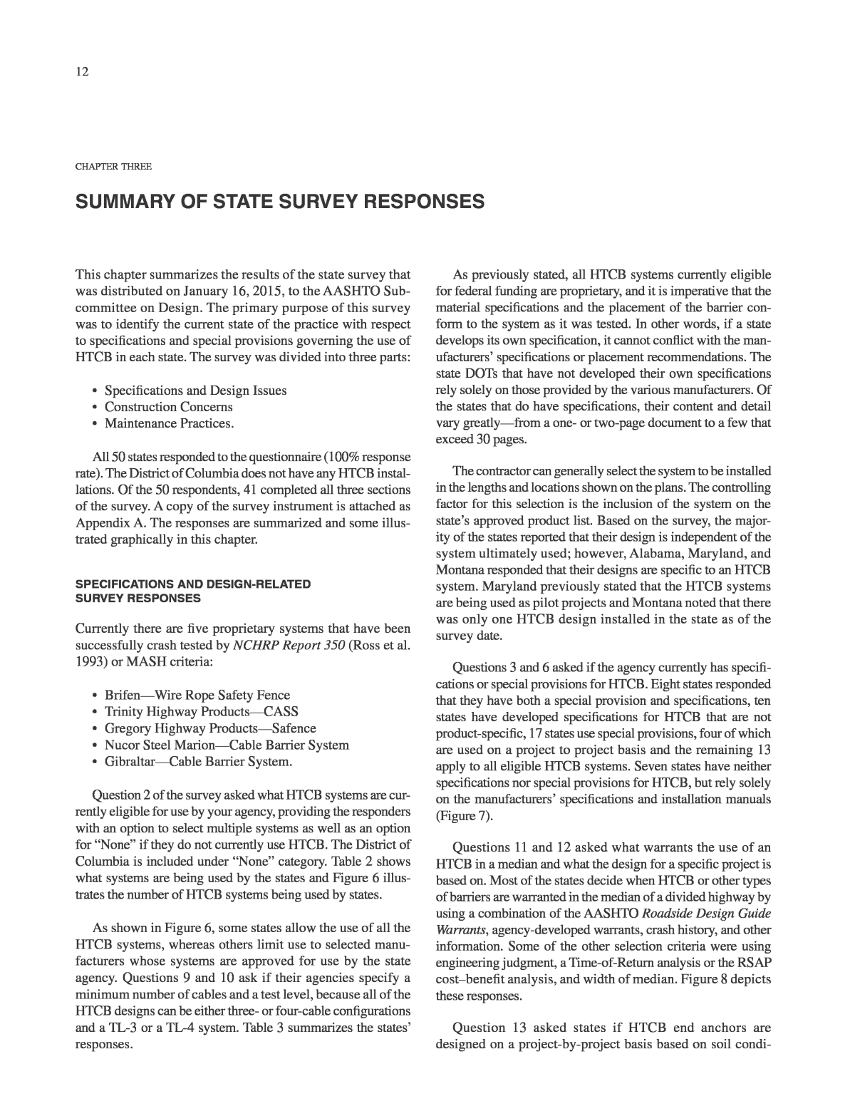
12 As previously stated, all HTCB systems currently eligible for federal funding are proprietary, and it is imperative that the material specifications and the placement of the barrier con- form to the system as it was tested. In other words, if a state develops its own specification, it cannot conflict with the man- ufacturersâ specifications or placement recommendations. The state DOTs that have not developed their own specifications rely solely on those provided by the various manufacturers. Of the states that do have specifications, their content and detail vary greatlyâfrom a one- or two-page document to a few that exceed 30 pages. The contractor can generally select the system to be installed in the lengths and locations shown on the plans. The controlling factor for this selection is the inclusion of the system on the stateâs approved product list. Based on the survey, the major- ity of the states reported that their design is independent of the system ultimately used; however, Alabama, Maryland, and Montana responded that their designs are specific to an HTCB system. Maryland previously stated that the HTCB systems are being used as pilot projects and Montana noted that there was only one HTCB design installed in the state as of the survey date. Questions 3 and 6 asked if the agency currently has specifi- cations or special provisions for HTCB. Eight states responded that they have both a special provision and specifications, ten states have developed specifications for HTCB that are not product-specific, 17 states use special provisions, four of which are used on a project to project basis and the remaining 13 apply to all eligible HTCB systems. Seven states have neither specifications nor special provisions for HTCB, but rely solely on the manufacturersâ specifications and installation manuals (Figure 7). Questions 11 and 12 asked what warrants the use of an HTCB in a median and what the design for a specific project is based on. Most of the states decide when HTCB or other types of barriers are warranted in the median of a divided highway by using a combination of the AASHTO Roadside Design Guide Warrants, agency-developed warrants, crash history, and other information. Some of the other selection criteria were using engineering judgment, a Time-of-Return analysis or the RSAP costâbenefit analysis, and width of median. Figure 8 depicts these responses. Question 13 asked states if HTCB end anchors are designed on a project-by-project basis based on soil condi- This chapter summarizes the results of the state survey that was distributed on January 16, 2015, to the AASHTO Sub- committee on Design. The primary purpose of this survey was to identify the current state of the practice with respect to specifications and special provisions governing the use of HTCB in each state. The survey was divided into three parts: ⢠Specifications and Design Issues ⢠Construction Concerns ⢠Maintenance Practices. All 50 states responded to the questionnaire (100% response rate). The District of Columbia does not have any HTCB instal- lations. Of the 50 respondents, 41 completed all three sections of the survey. A copy of the survey instrument is attached as Appendix A. The responses are summarized and some illus- trated graphically in this chapter. SPECIFICATIONS AND DESIGN-RELATED SURVEY RESPONSES Currently there are five proprietary systems that have been successfully crash tested by NCHRP Report 350 (Ross et al. 1993) or MASH criteria: ⢠BrifenâWire Rope Safety Fence ⢠Trinity Highway ProductsâCASS ⢠Gregory Highway ProductsâSafence ⢠Nucor Steel MarionâCable Barrier System ⢠GibraltarâCable Barrier System. Question 2 of the survey asked what HTCB systems are cur- rently eligible for use by your agency, providing the responders with an option to select multiple systems as well as an option for âNoneâ if they do not currently use HTCB. The District of Columbia is included under âNoneâ category. Table 2 shows what systems are being used by the states and Figure 6 illus- trates the number of HTCB systems being used by states. As shown in Figure 6, some states allow the use of all the HTCB systems, whereas others limit use to selected manu- facturers whose systems are approved for use by the state agency. Questions 9 and 10 ask if their agencies specify a minimum number of cables and a test level, because all of the HTCB designs can be either three- or four-cable configurations and a TL-3 or a TL-4 system. Table 3 summarizes the statesâ responses. chapter three SUMMARY OF STATE SURVEY RESPONSES
13 tions. Thirty-one states responded that they require the man- ufacturers of the systems to design the anchors and 11 use the HTCB manufacturerâs standard crash-tested anchor design. Question 15 asked how is the placement and spacing of the HTCB anchors determined. Sixteen states reported spacing is determined by the agency based on the stateâs specifications and 19 require the manufacturer to recommend anchor place- ment and spacing. Some states set minimum and maximum cable runs between anchors. Utah DOT has installed runs ranging from 2,000 ft to more than 45,000 ft. In most cases the need for emergency vehicle crossovers limits the practical length of barrier between anchors. Although most HTCB systems allow driven posts, most state agencies reported the use of socketed posts to facilitate repair and replacement after an impact. Twenty-five states that responded to Question 16 noted that they required the manufacturer to design the size and depth of the footings based on existing soil conditions, but that 15 states used whatever design was used in the crash testing of the system; that is, a âstandardâ design. Maine reported that it uses only driven posts. Because of the high tension in all proprietary cable sys- tems, posts that are not in a direct line with the end anchors may be subjected to additional forces. Posts along a horizon- tal curve will have greater lateral forces, possibly resulting in leaning posts. Posts located at the bottom of a sag verti- cal curve may be pulled upward, effectively raising the cable heights above the ground line. Similarly, cables on posts near the top of a crest vertical curve may be lowered, depending on the cable-to-post connection and post embedment details. Sixteen states responding to Question 16 reported that they follow the manufacturersâ recommendations in such cases, five modify the design in-house, and 19 do not make any modifications to standard post design or spacing. Nevada requires a design modification for any post spacing exceeding 10.5 ft and Texas requires modifications for some horizontal curves. HTCB Manufacturers No. of States Brifen 40 Trinity 38 Gibraltar 35 Nucor 26 Gregory 25 None 9 TABLE 2 HTCB BEING USED BY STATE FIGURE 6 HTCB currently in use.
14 High-tension cable barriers are most commonly used in freeway medians to prevent crossover crashes. However, free- way facilities generally include median bridge piers and twin bridge overpasses that can only be shielded with semi-rigid or rigid barriers. Question 20 of the asked how the state DOTs addressed the interface or overlap of the two different systems. Essentially four choices exist: 1. Terminate the cable barrier in advance of the stiffer system. 2. Terminate the cable barrier behind the stiffer system. 3. Connect the cable barrier to the stiffer system (exclud- ing concrete barrier). 4. Terminate the cable barrier in front of the stiffer sys- tem (excluding concrete barrier). Figure 9 shows the first option. Because the downstream terminal is a gating design, this treatment can leave a gap in median coverage, especially if located on the outside of a horizontal curve. If both terminals are impacted, it becomes a greater maintenance concern as well. Figure 10 illustrates the second option. If the metal beam guardrail is long enough to shield the opening between the twin bridges, this design can work well. It is important that the HTCB be offset from the guardrail to reduce the chances of an impacting vehicle rebounding from the cable into the field side of the w-beam. Figure 11 shows Option 3, connecting the cables directly to a w-beam, thus eliminating the need for a separate HTCB No. of StatesCables/Test Levels Minimum number of cablesâ3 8 Minimum number of cablesâ4 24 Do not specify a minimum number of cables 10 Minimum system Test Levelâ3 28 Minimum system Test Levelâ4 19 Do not specify a minimum Test Level 2 TABLE 3 NUMBER OF CABLES AND TEST LEVELS BY STATE FIGURE 7 HTCB special provision and specifications by state.
15 FIGURE 8 Warrant factors by state. anchor. This design is best suited for use at locations where a new HTCB can be connected to an existing w-beam installa- tion shielding a bridge end, when the w-beam is structurally connected to the bridge. Some state agencies have experi- enced problems with w-beam post movement caused by the high tension in the cables. A short section of w-beam should not be installed in place of a crashworthy HTCB anchor as was done in Figure 12. The inadequate performance of this design is seen in Figure 13. NCHRP Report 711 recom- mends a minimum of 75 ft of w-beam downstream from the last cable anchor when connecting to w-beam (Marzougui et al. 2012). The last option is effective as long as the cable is extended to the beginning length of need of the w-beam and the w-beam terminal is a minimum of 4 ft behind the cable, as shown in Figure 14. The only disadvantage to this design is that the cable terminal is in a vulnerable position and, if struck, the cable tension would be lost. Whenever practical, HTCB ter- minals are to be located in areas where they are least likely to be hit by errant motorists. Although the state responses to this question varied in detail, at least one of these four alternatives was used in each state. Two states reported that they do not allow any overlap, FIGURE 9 Terminating the HTCB in advance of w-beam. FIGURE 10 Terminating the HTCB behind w-beam.
16 that did not require concrete foundations, thus making them easier to construct and maintain and repair. CONSTRUCTION-RELATED SURVEY RESPONSES Few construction issues were noted by respondents. One state reported that neither the construction contractor nor DOT per- sonnel had any previous exposure to HTCB installation and relied heavily on the system manufacturer for advice. The only other common concern was movement in the anchor blocks or failure of the post footings in crashes. However, these are pri- marily design or maintenance issues and not directly applicable to system installation. MAINTENANCE-RELATED SURVEY RESPONSES Unlike most longitudinal barriers, HTCB systems do require continuing observation and actions after installation to main- tain optimal performance. FIGURE 11 HTCB connected directly to w-beam. FIGURE 12 Short section of w-beam installed as an âanchor.â FIGURE 13 Inadequacy of HTCB connection to short run of w-beam. FIGURE 14 HTCB terminated in front of w-beam. ending the HTCB in advance of any w-beam or concrete bar- rier and providing an acceptable terminal or crash cushion on the stiffer barrier. The majority of the reporting states indi- cated that the preferred treatment is to terminate the HTCB behind an existing barrier, taking into consideration the lat- eral distance between the two systems and the likelihood of an impacting vehicle being âtrappedâ between them. Only a few states noted that they flare the approach end/terminal of the w-beam rail and connect the HTCB cables directly to the guardrail itself, thus eliminating the need for a separate cable anchor. The rest of the respondents indicated that the HTCB overlapped the road side of the w-beam and was terminated with its own anchor. The survey asked responders to identify any design- related concerns that were not specifically addressed in the questionnaire. Most expressed concerns related to HTCB placement on slopes, an issue that has received a significant attention and been the subject of several research efforts, some of which are on-going. Others asked about anchor design for various soil conditions or the possibility of developing anchors
17 The survey asked responders to identify who is respon- sible for maintaining HTCB after it is installed. Twelve states reported that their state (or in one instance, county) person- nel are 100% responsible for maintaining HTCB after it is installed. Seven states reported that the work was done solely by contract, as shown in Table 4. The remainder of the responding states reported a split responsibility between maintenance forces and contractor personnel, with the state/contract ratio ranging from 5%/95% to 95%/5% (Table 5). The survey asked how frequently the cable tension was checked; however, there may have been some confusion with this question because only 20 states reported that the cable tension was checked after the initial installation. At opposite ends of the spectrum, one state reported checking tension every week and one every 2 years. Most states did report that the cable tension was checked following minor and/or major repairs (Table 6). Because of the high tension in the HTCB systems and the relatively recent introduction of these designs in the United States, training is highly desirable for all persons involved in installation, maintenance, and repair. In addition to state DOT personnel, police and emergency responders need to have a working knowledge of the systems whenever a vehi- cle becomes entangled in the cables in a crash. Virtually all state specifications or special provisions require the cable manufacturer to provide pre-installation training for the con- tractor and state inspectors. At least one state required that all members of the installation crew be certified by the manu- facturer as successfully completing training. Most states also offered training to police personnel and emergency respond- ers upon completion of an installation, and some provided such training when requested. Only two states noted that no training was provided to police or EMT personnel. Slightly less than one-third of the state respondents added comments or concerns related to maintenance issues. By far the most common complaint was that the many added miles of median barrier resulted in an increased number of impacts that required repair. Several northern tier states acknowl- edged that there were many hits during the winter months and that repairs were difficult under frozen-ground condi- tions. Others noted that spare parts were often difficult to obtain, especially when multiple proprietary systems were in use in a particular state. None of the states identified extract- ing vehicles trapped by the cables as a concern; how ever, one did indicate a serious injury to a maintenance worker when a cable snapped during accident clean-up. Although not mentioned in the survey responses, anecdotal evidence has shown vehicle extraction to be a concern in other states. Agency Staff (100%) Arkansas, Colorado, Kansas (with exception of terminals), Maine, Minnesota, Montana, Nebraska, New Mexico, New York, Utah, Washington State, Wisconsin Contractor Staff (100%) Arizona, Idaho, Mississippi, North Carolina, Rhode Island, Tennessee, Virginia TABLE 4 STATES WITH 100% AGENCY OR CONTRACTOR PERSONNEL MAINTAINING HTCB States Agency Staff Contractor Alabama 75% 25% Delaware 95% 5% Florida ~10% ~90% Iowa 20% 80% Illinois 10% (est.) 90% (est.) Indiana 90% 10% Kentucky 100% Louisiana 5% 95% Michigan 94% 6% Ohio 20% 80% Oklahoma 70% 30% Texas 40% 60% West Virginia 30% 70% TABLE 5 STATE MAINTENANCE: PERCENTAGE BY AGENCY AND CONTRACTOR STAFF Frequency State Response After Installation 20 Every 6 Months 1 Every Year 9 Every 2 Years 1 After Minor Repairs 13 After Major Repairs 23 Other North Carolinaâweekly Coloradoâper manufacturers recommendations Floridaânot currently specified Idahoânone currently installed Illinois, Oklahoma noticeable sag TABLE 6 FREQUENCY OF CABLE TENSION CHECKED BY STATES
