
4
Information Technologies Pertinent to the Materials Selection Process
This chapter discusses the key materials-specific information technologies required to produce the CAMSS diagramed in Figure 3-1. This chapter is divided into two sections: "Databases and Knowledge Bases," which pertains to the first two boxes at the top of Figure 3-1, and "Modeling and Analysis Systems," which pertains to the third box at the top of Figure 3-1. This chapter focuses on the use of computer-aided systems as tools or aides to design teams. Full-function automated systems currently require significant break-throughs in areas of frontier research and are particularly weak in tasks demanding creative insight.
DATABASES AND KNOWLEDGE BASES
As shown in Chapter 3, a CAMSS requires access to and application of materials databases and knowledge bases at every stage of use. In the ideal case, electronically stored knowledge about materials and design details could be provided automatically to the design team from databases and knowledge bases at appropriate levels of sophistication. This section provides a brief overview of the levels of knowledge representation in the automation of technical memory and discusses the principal methods for representing materials knowledge within a CAMSS to facilitate the design process. Appendix A contains a brief overview of some of the knowledge representation techniques discussed in this chapter.
Levels of Representation
The basic level of electronic knowledge representation is an electronic library (i.e., databases and knowledge bases). In this scenario, a human designer would perform essentially the same tasks as previously, but instead of searching for information through written material, the search would be conducted through screens. The screens could present prior designs, lessons learned, design guidelines, or standards. While electronic searches have advantages over manual searches, the cost of implementing all the necessary reference material electronically would be high and probably could not be justified based solely on productivity gains. However, since most documentation is currently being created electronically, this is a significant issue only for older reference material.
In its simplest conception, the electronic database or knowledge base would have no more embedded reasoning power than books (i.e., the user supplies all the reasoning). Three advantages of this basic type of knowledge representation are that (1) it is easy, in principle, to implement; (2) it is represented in natural language, with all its flexibility; and (3) it automatically makes the most recent versions of material available.
A higher level of sophistication would, continuing the analogy, consist of a reference book that opens automatically to the desired page and then, based on a user request, highlights that part of the page which the user needs. This requires a mechanism or process for the user to describe the reason and criteria for searching the reference book.
In a limited sense, such searches have been available for a long time in databases and knowledge bases using key words and indexing schemes. While keywords and index schemes are useful in restricting the material that will later have to be scanned by the human expert, these schemes are not very intelligent because a great deal of information is often presented that is totally irrelevant to the problem at hand. Keywording, moreover, works on alphanumeric information but is not easily adapted to other information types such as shapes, colors, and graphs. The technology to support multimedia, interactive reference books is now emerging (ACM, 1993; IEEE,
1993). This capability is an advance in that the author has pre-programmed expected search requests.
A higher level of sophistication of electronic representation of technical memory would be the equivalent of an educated assistant or technician that can search the library and retrieve the pertinent information in the background without direct user involvement. Representing the knowledge that an electronic assistant contains and representing the knowledge that the user requires are two different problems, however. For the materials selection problem in structural design, the intelligent electronic assistant would have to understand, at some level of competence, the information provided by the human experts. That information would consist not only of concepts used in materials science and engineering but concepts related to the entire life-cycle of design, manufacturing, inspection, and disposal or recycling. In the ultimate case, the electronic assistant will have to know the languages of many different pertinent databases and then be capable of representing that knowledge in a consistent form. This leads to the need for the intelligent integration of information from these multiple sources.
The highest level of sophistication envisioned would provide a full-function, computer-aided electronic assistant or technician who could not only find the correct reference material but also apply the results to the query to the design problem at hand. Just as we can imagine human assistants of different levels of skill, so we can also imagine electronic assistants at different levels of utility. As mentioned earlier, full automation of databases or knowledge bases to perform the complete design task is not currently feasible. However, certain select routines or computationally intensive tasks now performed by people can be performed by electronic assistants to provide particular advice or to critique selected aspects of the design. For instance, there has been considerable research into Agent Technology, whereby a user can specify an agent to roam the Internet to obtain appropriate information (ACM, 1994). This technology requires the use of data dictionaries or mediators, however, to recognize and translate the relevant information in different databases and knowledge bases and to integrate possibly conflicting data from multiple sources. This level of capability has been shown to greatly benefit the overall performance of the design teams in several limited instances (Klahr et al., 1987; Famili et al., 1992). For example, the three areas of expertise—product design, materials selection, and manufacturing—cannot be entirely separated for highly engineered products. Materials properties depend to an extent on the processing route, and processing considerations can be influenced by design constraints. Similarly, the design must reflect the reality of available material properties, and the properties are not completely independent of the design application (e.g., high loading rates can reduce a material's fracture toughness).
Issues Concerning Knowledge-Base Development
Reliance on standard databases that contain physical and mechanical properties is inadequate to support materials selection processes fully. Knowledge bases are required that capture the advantages and limitations of materials, their processability, and their application histories—all of which are critical to the design process. There are problems related to the definition, development, and construction of knowledge bases, however.
Definition of Knowledge Bases
While much has been written about knowledge bases, there is little agreement on the scope of what exactly constitutes one. There are wide variations in the literature describing designs and implementations of computer-aided systems.
Many companies have custom-built basic systems for their own applications. Table 4-1 summarizes representative computer-aided system application areas that relate to the materials information used in the design process in a manner consistent with the vision discussed in Chapter 3 . These applications are considered state of the art in the sense that examples can be found either in use or under development at major government and industrial sites.
Table 4-1 shows that there is a wide breadth of knowledge base applications. The list is also incomplete, since it only represents what is currently possible in the design and engineering phase of product development. If the scope were broadened to other phases of the product life-cycle, more applications could be listed that would require knowledge (e.g., diagnosis of the manufacturing process). Further work is required to determine what constitutes a knowledge base and how it differs from simple databases.
Table 4-1 Representative Applications Based on Knowledge of Materials
|
Application |
Description |
Knowledge Required |
|
Selecting Materials |
Assist the product designer in selecting the best material for the product. |
Materials, performance, and processing knowledge. |
|
Cost Estimation |
Determine the manufactured cost of a product based on a parametric description of it. Could include full life-cycle costs. |
Cost of raw material and costs associated with design, validation, manufacture, and disposal methods for various materials. |
|
Manufacturing Process Planning |
Develop a process or assembly plan for a product. The depth of detail can vary from process routing to instructions for controllers. |
Manufacturing methods and processing data associated with various materials. |
|
Predictive Analysis |
Predict the performance of a product. Many dimensions of performance (e.g., stress, wear, and kinematics) can be analyzed. |
Materials properties and characterization of usage of materials. |
|
Manufacturability Advisor |
Critique a product design, process plan, or operations plan regarding the efficiency, product quality, and cost of production. |
Manufacturing knowledge about materials and the manufacturing processes associated with the materials. |
|
Requirements Allocation and Balancing |
Provide assistance to the product designer to allocate and balance requirements in formal requirements processes such as Quality Function Deployment. |
Knowledge of the relationship of materials to the characteristics defined in the requirements flow down process. Examples include durability of materials, surface quality for finishing, and mass. |
|
Search for Prior Designs/Products |
Assisting product designer in finding most similar products from a library of products to take advantage of prior experience. Prior products using similar materials may be interesting even if product was quite dissimilar. |
Any material properties may be of interest. Knowledge of similarities between materials and relationships between materials and product and process performance and cost. Repository of prior designs and product information. |
|
Searching Standard Components |
Assist in selecting a standard component from a library of standard components. |
Any material properties of the standard components that are relevant to the cost and performance of the product. |
|
Tolerance Analysis and Allocation |
Predict the variability of the manufactured part with respect to geometric dimensions and other key product characteristics. |
Knowledge about the relationships between materials and the manufacturing processes and manufacturing equipment. |
|
Prototyping |
Assistance can include selecting the best material for the prototype and the prototype tooling based on the materials used in the product. The prototype can be constructed with varying degrees of production-intent tooling. |
Knowledge of any material properties and similarities of materials to be used for prototype and prototype tooling to those to be used in production. |
|
Robust Design |
A formal three-step process for producing high-quality, low-cost products. |
Knowledge of material properties are used in the system design phase in deciding required features, functions, and product parameters. Knowledge of materials is used in the parameter design process to consider reliability and manufacturability of the components. Finally, in the tolerance phase, material properties are used to adjust product parameters to achieve broad ranges for manufacturability. |
|
Trade-Study Methods |
Assist the product designer in making choices with respect to product features, function, and manufacturing. |
Knowledge of materials and how they relate to key product characteristics can be used in the evaluation of alternatives. |
Development of Knowledge Bases
The absence of specific guidelines for the building of databases and knowledge bases about materials and the higher software development costs necessary to obtain generality and robust performance are barrier to the quick and effective proliferation of the use of databases and knowledge bases in material selection (or other fields as well). Knowledge base applications are currently developed in several different ways.
Some basic, commercial, knowledge base applications exist that the user community can acquire, install, and customize by loading site-specific models, information models, and information. One example of such an application is in the domain of cost estimation. This application allows the user to build parameterized product descriptions that incorporate relevant attributes that influence cost and manufacturability, material models that include parameters that impact cost, and process descriptions that link models of processes to the product and material attributes. The user can then employ a simple spreadsheet-like language to match processes and material to products and to compute cost estimates.
More advanced knowledge base systems can also be developed by using application shells or knowledge-engineering tools that implement knowledge base techniques developed by the artificial intelligence community to solve a variety of problems (e.g., diagnosis, simulation, and scheduling). An application shell is often a library of modules that can be used to assemble an application in some broad area and rapidly provide an environment for capturing and representing expertise in the form of rules and the knowledge structures. The advantage of using shells is that they permit the user to concentrate on representing the knowledge rather than attending to low-level programming tasks. Application shells do require tailoring, modification, and extension before use. Typically, a knowledge-engineering effort must first be undertaken to perform knowledge acquisition and routine programming tasks. For application shells, the cost of customization is often offset by the reduced cost for generality in the software. As with complete applications, many companies have internal products that they distribute to a number of sites.
Construction of Knowledge Bases
Two final barriers to the construction of knowledge bases are the higher hardware costs and the inherent nature of expert knowledge. The construction of knowledge bases require technologies beyond the standard manual entering of pertinent pieces of information. For instance, digital scanning combined with character-recognition technology can be used to enter application history, such as failure analysis results. Digitizing tables and figures using data capture software can allow each semantic element and semantic relation expressed in the tables and figures to be stored in a searchable file. Graphs can be made searchable for specific data, interpolated data, and extrapolated data. Audio-visual and multimedia digital storage and presentation are becoming common-place on engineering workstations. The appropriate assignment of recordings of design engineering discussions in knowledge bases will pose a significant research challenge. Annotations to diagrams relating key design decisions and constraints would also assist others in understanding the reasons for a particular choice.
Issues Concerning Database Development
The material databases needed during the design process are not openly available to U.S. industry. Some government and privately sponsored organizations, such as the Department of Defense's Information Analysis Centers and the National Materials Property Database Network (Appendix C ), have made a start, but industrial data limitations have resulted in their falling short of the needs for knowledge base approaches to design.
The situation is currently little better than it was in 1983 when a National Materials Advisory Board report stated: "There is no national policy in the United States directed toward a rational system of materials properties data management and the situation in this area is best described as chaotic" (NRC, 1983). There is still no leadership for collecting, generating, validating, and updating the data needed for structural design. Most organizations will agree, however, that a certified database is a valuable asset. As recommended in a more recent National Materials Advisory Board study (NRC, 1993): "a federal agency, such as the National Institute of Standards and Technology, could establish a forum to
develop the standards through timely, active participation by industry and other interested parties.''
MODELING AND ANALYSIS SYSTEMS
As shown in Chapter 3, a CAMSS must have modeling and analysis systems to analyze the information available in databases and knowledge bases. This section examines the modeling and analysis systems pertinent to the materials selection process: Geometric Reasoning, Process Modeling, and Modeling for the Abstraction of Downstream Constraints.
Geometric Reasoning
Most CAD systems currently in industry are used primarily for drafting purposes with some analytical support. The level of graphic rendering has reached an impressive level, but all design decisions are essentially made by the design engineer with little or no decision support, or reasoning, other than visual feedback. Reasoning falls into the two major categories of synthesis (i.e., the systematic creation of alternatives as the product design and the design process become increasingly more specific) and abstraction (i.e., the elimination of possible design alternatives by downstream concerns and constraints, such as performance and manufacturability). The term abstraction is used since, in most instances, detailed downstream concerns (e.g., manufacturability, maintainability, or recyclability) need to be either simplified or abstracted to become more readily understandable by an engineer at an early stage of the design process. As discussed in the previous section, the designer should receive feedback about the consequences of a decision at a variety of different support levels and from a variety of different viewpoints (e.g., materials considerations, product performance, manufacturing, cost, service, and reliability).
Geometry plays an important role in design, yet many initial design decisions are made independently of geometric considerations. The final decisions in product design almost always involve form and geometric constraints. An example of such an information flow in an industrial setting is to imagine a car design team that is synthesizing a new car body. The current manufacturing approach would be to spot-weld several hundreds of pieces of sheet metal together to fit the part geometry. A possible alternative is an assembly of lightweight aluminum beams on which plastic panels are mounted. This design is called a space frame. However, to make an intelligent decision about whether this alternative design has merit, a design group must understand the essence of the aluminum casting and extrusion processes, the microstructures that result, the properties of the beams, and the methods for joining the pieces. This means simplifying the details of the process to the extent that someone with little materials expertise can take this information as the basis for performing design tradeoffs. The faster and more efficiently the manufacturing process and materials performance constraints are presented to the designers, the faster and more efficiently they can synthesize a new product.
When reasoning about materials and assigning material properties to certain geometric objects, several things are important. In principle, all geometric models, whether based on elements of one, two, or three dimensions, can be linked to attribute-value pairs, such as materials properties, like Young's Modulus, with a specific value assigned. Some of these attributes may be related to material properties or to the specifics of a certain microstructure. In the evaluation of the geometry, the attribute-value pair mechanism must be able to inherit property structures. Furthermore, when the attribute or its associated value assume a specific characteristic, the mechanism should be able to trigger events automatically. Most commercial CAD/CAM systems do not currently have this capability, although it is an active research area.1 Significant research needs to be performed to create sound representational schemes with the described behavior, however.
Formal models are also not available at any level of representation that allows the derivation of structure-property relationships from first physics principles to an extent that a design engineer can benefit. One example is the field of dislocation theory (defect structure level). The flow stress (micro and macro material property level) of subgrain forming materials is understood to be proportional to the square root of the dislocation density, but the models currently available give only an order of magnitude relation for the proportionality factor in this relation.
A design engineer could benefit from such a materials science insight, however. It would help the designer to better understand the choice of a constitutive relation for FEA that is frequently used to determine the dimensions of load bearing components. The design engineer needs (computer-aided) decision-support tools that provide insight into materials science issues to consider material alternatives and processing tradeoffs effectively. Reasoning about materials needs to be closely coordinated with decisions regarding shape and geometry. Considering the earlier example of the car space frame, a novel design was created by combining material properties and processing knowledge with spatial layout.
Decision-support methodologies and tools that aid in synthesizing and finding constraints early on in the manufacturing process are also key to improving the quality and speed of product creation. Consider the following tool used for designing a side marker, a relatively simple component for a car (Figure 4-1). One side of this car side marker has strengthening ribs to increase the resilience. The system shown here recognizes certain geometric features that are important from a manufacturing materials viewpoint. Within that system, the designer receives feedback about whether the dimensions chosen are compatible with good manufacturing practice. Decision-support tools such as this can significantly reduce errors, cost, and development time. Their realization will largely depend on research performed to construct methodologies for representation in which geometric information can be properly linked with nongeometric information, like materials and processing knowledge and databases.
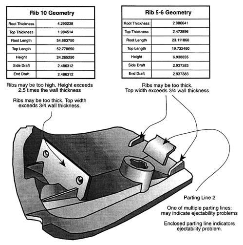
Figure 4-1 Automobile side marker.
Process Modeling
A process model is a mathematical representation or simulation of a process that allows problems to be solved in the computer rather than by empirical or experimental methods, especially trial-and-error techniques. Simulation is an important concept in the modern manufacturing organization. It uses mathematical models of real systems to test or predict the actual performance of the systems under various conditions. Through simulation, engineers and manufacturing personnel can test a design, analyze a procedure, or assess a process performance before implementing the real thing. Process modeling—discussed in the context of this report—deals with unit processes such as casting, forging, rolling, hot isostatic processing, heat treating, machining, chemical vapor deposition, and composite material fabrication. Constitutive modeling may be one of several elements in the overall process model. Constitutive models focus on predicting the mechanical response of a material as a function of prior processing history and internal structural parameters in response to externally applied forces. Process simulation could just as well apply to modeling the behavior of a Flexible Manufacturing Center or the simulation of the flow of information in a process plan. A simulation capability in the manufacturing setting can substantially decrease the energy, material waste, and time required to produce a product or implement a process.
A number of sequential steps are involved in any process modeling activity. These steps can be formalized and implemented in the computer as an activity model that is based on how the particular manufacturing enterprise does business, or they can be accomplished in a less formal mode of problem solving. The various steps involved in process modeling are listed in Table 4-2.
Process modeling is generally used to understand unit processes that require coupling of disparate physical phenomena. For instance, virtually all unit processes are governed by heat flow, fluid flow, plastic flow, stress, and phase transformations. These all can be modeled by a variety of numerical techniques. Several approximate numerical techniques for simulating material shaping and forming processes under arbitrary conditions have been used, including (1) the slab method (approximate stress analysis), (2) the slip-line method (method of characteristics), and (3) the upper-bound method (method utilizing an energy principle). Although these techniques contribute
Table 4-2 Steps in the Development of a Process Model
|
1. |
Define the problem and state the problem-solving objective. |
|
2. |
Develop the mathematical model in accordance with the problem. |
|
3. |
Collect model input data and specifications. |
|
4. |
Implement process model in the computer. |
|
5. |
Establish that the desired accuracy or correspondence exists between the simulation and the real system. |
|
6. |
Establish boundary conditions for using the model. |
|
7. |
Run simulations to obtain output file. |
|
8. |
Post-process the output values to draw inferences and make recommendations to solve the defined problem. |
|
9. |
Implement and document the decisions resulting from the simulation and documenting the model and its use. |
For fifteen years, the finite element method (FEM) has been applied to model a wide range of metalworking operations. FEM divides the volume of the plastically deforming material into a two-dimensional or three-dimensional network of discrete elements (finite elements). The deformation at selected points (nodes) is determined by the application of solid mechanics principles.
Specialty FEM analysis codes for process modeling currently have been developed for analyzing almost every class of unit-manufacturing process. The processes that have been simulated include machining, heat treating, sheet metal forming, shape rolling, ring rolling, extrusion, forging, powder consolidation and forging, superplastic forming/diffusion bonding, cogging, and radial forging. At least one of the commercially available three-dimensional codes is capable of concurrently modeling the equipment, the dies, and the workpiece's response to the boundary conditions, including the effects of different heat sources such as induction and resistance heating on the material flow behavior and the die reaction (Kiridena et al., 1989).
Almost every detail of a unit process can be modeled by FEM analysis, including predicting the evolution of microstructure and properties in the finished shape. The latter is made possible through the use of a technique
known as dynamic material modeling (DMM), which uses constitutive relationships that define the evolution of metallurgical structure on a scale that ranges from the microscale of dislocations, precipitates, dislocation networks, and grains to the macroscale of laps, shear bands, and grain flow lines (Richmond, 1992).
DMM defines the intrinsic workability of the workpiece material at the macroscale level of structure in terms of mechanical and structural stability. This material model enables the process design engineer to define the control space for a stable process, including the number of preform shapes, the die velocity and temperature ranges, and the die geometries. Within the domains of the stable control space, where the activation energy is fairly constant, microscopic models can be used to predict structural evolution. The end result is a product having a controlled set of structures and properties in the finished shape.
As an example, the group of processes that can be described broadly as casting processes are now being simulated by several numerical methods. Processes of this type are investment casting, permanent mold casting, die casting, squeeze casting, and plastic injection molding. The approach to designing these processes by process simulation is fundamentally the same as for any other process.
A choice of numerical methods are available for this class of problem. The finite difference method, boundary element method, and FEM have been used for modeling the behavior of casting processes that are controlled by coupled thermal, fluid, and stress phenomena. Both the finite difference method and the boundary element method can be used when the material properties are linear and the product geometry is relatively simple. However, when the problem couples thermal, fluid, and stress phenomena, the FEM modeling technique is superior.
One example of incorporating material behavior during processing conditions is the use of experimental castability maps that are expressed in terms of the fundamental variables predictable by the process model. These maps provide a framework for modeling the casting process at the macro or continuum level of analysis. Like DMM, which predicts stable plastic flow, the castability maps define the domains where certain microstructures or defects will form when certain ratios of R/G occur, where R is the interfacial velocity and G is the temperature gradient at the solid/liquid front. These modeling parameters were derived from first principle understanding of the nucleation growth kinetics.
Micromodels can be integrated with the macromodels for predicting the evolution or occurrence of microstructural features. More effort is required to expand the number of micromodels to cover all possibilities, however. Mechanical property predictions are not yet possible because very few correlations have been made with microstructures and thermomechanical histories. These models suffer from not incorporating the knowledge of the basic physical mechanisms involved.
Models can be used to better inform suppliers on their process requirements. For example, cast products are usually considered to have inferior properties to wrought products because of the large variation in mechanical property values that can be found in the same cast product produced by different vendors. Process modeling can reduce the scatter from vendor to vendor by specifying to each vendor the desired thermomechanical history for a given component.
Thermophysical property data play a key role in modeling many unit-processes such as investment casting, welding, crystal growth, glass making, microwave processing, and composites production. A critical need exists for measuring and archiving high-temperature thermophysical property data for materials in the liquid, solid, and biphasic states. The important properties include emissivity, heat capacity, heat of fusion, melting temperature, density, surface tension, thermal diffusivity, and materials viscosity as a function of temperature and shear strain rate.
Comprehensive thermophysical properties, constitutive models for nonlinear behavior, intrinsic processing maps, and databases of microstructure-property relationships are needed for industrial process modeling as influenced by prior thermomechanical history. This database should represent a standardization of materials process design data that are certifiable in order for them to be useful to manufacturers. The database information currently used in process modeling is generally typical data, and the statistical assurance associated with such values is not known. Accurate error estimates in process model predictions require information regarding the statistical distribution of the input data.Modeling of Abstraction of Downstream Constraints
As stated previously in this chapter, the design tradeoffs to be taken into account in concurrent engineering also must meet performance capability constraints such as inspectability, maintainability, and reliability. Inspectability during manufacturing and product service are not yet generally considered in the design process. However, recent difficulties with inspectability of aging aircraft (Achenbach and Thompson, 1991) have clearly indicated the need for incorporating inspectability at an early design stage.
Figure 4-2 shows the diagram of a concurrent engineering environment that links design to inspectability and the other downstream capability constraints, as well as to areas such as quality assurance, life-cycle costs, and materials and processes. At the present time, the only links that have been developed are the CAD/CAM links between design and manufacturing methods and processes.
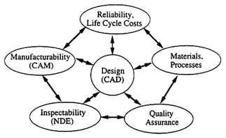
Figure 4-2 Concurrent engineering environment including inspectability. Reprinted courtesy of D. Thompson and L. Schmerr, Center for Nondestructive Evaluation, Iowa State University.
Computer models for other downstream capability constraints can provide key ingredients for implementing the complete concurrent engineering environment of Figure 4-2. In an early stage of the design process, models can be used to determine the role of such procedures as nondestructive evaluation (NDE) for in-process control of important parameters in the manufacturing process and for in-service use and in-the-field inspections. They also play an essential role in a damage-tolerant design philosophy and in questions of in-service reliability and life-cycle costs. Significant progress has been made in establishing NDE models and in building the other concurrent engineering links, such as through the joint National Institute of Standards and Technology, Iowa State University, and Northwestern University Program in Integrated Design, NDE, and the Manufacturing Sciences.
Measurement Modeling
The availability of a measurement model has many benefits. Numerical results based on a reliable model are very helpful in the design and optimization of efficient testing configurations. A good model is indispensable in the interpretation of experimental data and the recognition of characteristic signal features. The relative ease of parametric studies based on a measurement model facilitates an assessment of the probability of detection of anomalies. A measurement model is a virtual requirement for the development of an inverse technique based on quantitative data. If tested for accuracy by comparison with experimental data, it provides a practical way of generating a training set for a neural network or a knowledge base for a computer-aided system. Finally, and most importantly in the present context, these models can be incorporated into a concurrent engineering design process.
One of the most significant advances in nondestructive evaluation over the last decade has been the evolution of quantitative nondestructive evaluation (QNDE) from a conglomeration of empirical techniques to a well-defined field interdisciplinary science and engineering. In the course of this development, it has become well recognized that a fundamental approach to QNDE must be based on quantitative models of the measurement processes of the various inspection techniques. A model's principal purpose is to predict, from first principles, the measurement system's response to specific anomalies in a given material or structure (e.g., cracks, voids, distributed damage,
corrosion, or deviations in material properties from specifications). Thus, a measurement model must include the configuration of probe and component being inspected and a description of the generation, propagation, and reception of the interrogating energy. For example, in the case of ultrasound as interrogating energy, this description requires computations of the transducer radiation pattern, refraction of the beam at the part's surface, the beam profile, and the propagation characteristics in the host material including effects of material anisotropy, attenuation, and diffraction losses. Detailed modeling of the field-flaw interactions that generate the measurement system's response function are also included, as well as information on material properties and other conditions that increase variability and add uncertainty to the measurement results. A well-constructed measurement model should be able to predict specific instrumental responses to any anomalies in complex materials and structures as well as to any standard flaws placed in various calibration blocks. The status of models for ultrasonics, eddy current methods, and radiographic techniques has recently been discussed by Gray et al. (1989).
Quantitative Nondestructive Evaluation
This section discusses QNDE as a measurement model and its application to a damage tolerant design philosophy and detection probability. The coupling of measurement models to CAD is also reviewed.
The load-bearing capacity of a structural system can conventionally be determined by applying increasingly larger loads until the structure fails. Such proof testing is part of the design process. Once a structure is in service, a proof test is obviously not a practical way to assess a part's condition. A feasible approach to obtaining strength information under in-service conditions is by using a QNDE technique, whereby a material or a structure is evaluated through interaction with some form of interrogating energy. Many forms of radiated energy have been used in QNDE (e.g., laser light, ultrasound, eddy currents, and x rays). Other techniques are based on the penetration of neutron and thermal waves. The QNDE approach includes the development of nondestructive measurement procedures to determine material properties and to detect flaws and other failure-related conditions. QNDE also encompasses the design of instrumentation, data processing, the use of measurement models, and the interpretation of data to determine whether a part should be rejected or a structural system should be repaired. QNDE procedures should be considered in the design stage as part of quality assurance, maintainability, and reliability analysis.
Fracture mechanics and failure mechanics have made great strides in the understanding and prediction of the integrity of structural components. For a component made of a material of known properties subjected to a given set of loads, it is possible to calculate the critical size of a crack at a specified location. A component is judged to be safe if the crack is smaller than a critical size and is not expected to grow to critical size during the service life or prior to the next inspection. Reliable methods must be available to detect and characterize cracks, including those of subcritical size. QNDE provides the technology to detect cracks (or more generally flaws) larger than the detectability limit and to determine location, size, shape, and orientation.
Damage-Tolerant Design
In a damage-tolerant approach, subcritical flaws just below the detection limit are assumed to exist at every fracture-critical location. As part of the analytical evaluation the following questions must be answered:
-
What is the critical flaw size that will cause component failure when subjected to known service loads and temperature conditions?
-
What are the driving forces causing crack growth?
-
How fast will a subcritical crack grow under service load and temperature, and hence, how long can a component containing a subcritical flaw be safely operated in-service?
-
What inspection must be performed to detect a crack before catastrophic failure of the component occurs?
Subcritical crack initiation and propagation occurs in high-stress areas and in locations where components contain material- and manufacturing-related inhomogeneities such as voids, inclusions, machining marks, or sharp scratches. Current programs require an inspection at half the time required for a potential crack to grow to critical
size. The inspection is assumed to detect any flaw larger in size than a defined limit (Cowie, 1989).
A systematic approach to the overall inspection requirements of structures is required within a CAMSS system to advise the designer about potential problems with inspection and possible design alternatives. This approach should take into account the statistics of the occurrence of flaws, the crack growth mechanisms, and the various nondestructive detection techniques. The probability of detection of certain classes of defects also depends on the load, damage deterioration properties of the material, inspection intervals, human factors, and replacement and repair methodologies.
Probability of Detection
The implementation of a measurement model should be coupled to the concept of probability of detection (POD). This is a statistical representation of the probability that a given measurement system will be able to detect a specific flaw (or condition) in a given material or structure. It incorporates knowledge of the signal detected by the measurement system together with statistical information concerning flaw distributions, instrumental noise, and threshold levels. A POD curve shows the probability of a flaw's detection as a function of flaw size for a specific inspection technique. For an ideal technique, the POD of flaws smaller than a size predetermined by performance requirements and material properties is zero, while the POD for any flaw greater than this size is unity. In this case, there are neither false rejections of good parts nor false acceptances of defective ones. However, NDE techniques in practice are never as sharp and as discriminatory as indicated by the ideal curve. Thus, there are regions of uncertainty with false rejections and false acceptances.
Figure 4-3, which was taken from Gray and Thompson (1986), shows the results of simulating the ultrasonic POD of circular cracks at different depths below a cylindrical component surface and for two different scan plans. The plot on the left illustrates the use of the POD model to quantify the detection capability of an NDE system. For the specific parameters in that simulation, cracks that are otherwise identical have significantly different detectability levels depending on their depth below the surface of the part. This example illustrates the use of the POD model both for quantifying the capability of a flaw detection system and for suggesting improvements in either the system or its operation that can improve its capability.
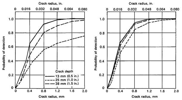
Figure 4-3 POD curves for two scanning plans. Source: Gray and Thompson, 1986.
Issues Concerning Implementing Modeling and Analysis Systems
If modeling and analysis systems in a CAMSS are to be useful and effective, future engineers must receive sufficient training in both the theory behind these systems and their application to the design process. A previous National Materials Advisory Board report entitled Enabling Technologies for Unified Life-Cycle Engineering of Structural Components stated that education in materials synthesis and processing is a barrier that must be mutually addressed by industry and U.S. institutions of higher learning (NRC, 1991). The time to introduce CAMSS and to perfect the skills in using the technique will be dependent on the availability of individuals with expertise in computer and materials science. Some engineers, such as manufacturing mechanical engineers, are highly skilled at using computers and doing FEA but do not have sufficient knowledge about the behavior of materials under processing conditions. In contrast, materials scientists and engineers have a better understanding of material behavior but lack sufficient training in the use of computers and computer-aided systems in manufacturing. Also, nondegreed technical personnel perform many crucial tasks throughout engineering and manufacturing that will be dependent on these new technologies. Institutions of higher learning will have to develop interdisciplinary programs led jointly by experts in materials science and engineering, design, and computer science if a CAMSS is to be properly implemented.


