
B
Trapped Ion Quantum Computers
This appendix reviews the technology used to create the quantum data plane and the control and measurement plan for trapped ion quantum computers. Since individual ions serve as qubits, the qubits themselves do not face the challenges of manufacturing defects; this approach has the potential of low error rate gate operations.
B.1 ION TRAPS
Atomic ions are trapped in space using electromagnetic fields. A point charge (an ion) cannot be stably trapped in free space using a static, or constant, electric field only, so either a combination of electric and magnetic fields (Penning trap) [1] or a time-dependent electric field (Paul trap) [2] must be used to trap arrays of atomic ions. These traps are operated in a vacuum to avoid interactions with background molecules in the environment.
Most trapped ion quantum computing systems use a Paul trap, where a radio frequency (RF) signal is applied to two electrodes arranged in parallel to ground electrodes, to form a quadrupole RF field (Figure B.1b). At the quadrupole “null”—where the RF field vanishes—atomic ions feel a trapping potential, which typically takes the shape of a line (Figure B.1a). Other electrodes carrying direct current (DC) fields can be used to create a nonuniform trapping field profile along the length of this line, which further confine and fine-tune the location of the trapped atomic chain [3]. Traditionally, these trap structures were constructed by machining and

assembling metal parts, similar to quadrupole ion mass spectrometers. New designs map the electrodes of a Paul trap onto a planar geometry [4] and use semiconductor microfabrication technologies, much like those used for classical computing hardware, to construct the trap structures (Figure B.1c) [5,6]. The adoption of microfabrication technologies could enable the creation of more complex trap structures and new mechanisms for manipulating the trapped ions—for example, shuttling across junctions [7-10]—which, as will be shown later, is critical for scaling up the number of qubits in these systems (Figure B.1d). These microfabricated traps have also accelerated the development of advanced features of the ion traps by integrating various optical [11-13] and microwave components [14-16]. Microfabricated ion traps within which high-performance qubit manipulations are routinely carried out, made by various academic institutions, government laboratories, and industry foundries today, have been adopted by research groups around the world.
B.2 QUBIT CONTROL AND MEASUREMENT
Once ions are held within a trap inside a vacuum chamber, they are laser-cooled to near the ground state of motion in order to remove random variations that can affect their multiqubit operations. It is important to note that the motion of the ions does not directly impact the qubit stored in the internal states of the atomic ions. Subsequently, electromagnetic radiation is used to operate on the qubit state. There are two main types of trapped ion qubits, defined by the physical states used to represent the qubit states: “optical qubits” and “hyperfine qubits.”
An optical qubit (Figure B.2a) makes use of the ground electronic state and a metastable excited electronic state of an ion, for which the energy difference between these levels is equal to the energy of a photon from the right “color” optical laser, the “qubit laser.” Optical qubits can be prepared and detected with efficiencies better than 99.9 percent, with coherence times in the range of 1 to 30 seconds. A significant technical challenge in the operation of optical qubits is maintaining control of the qubit laser to enable precise and coherent control of the qubits. This requires stabilization of (1) the laser’s output frequency over the time frame of qubit coherence (to approximately one part in 1014 or 1015), and (2) the overall optical path lengths that the laser beam traverses to within a fraction of the optical wavelength over the duration of the quantum computation (or, that of quantum error correction that can recover from the phase errors). This optical frequency precision is just achievable in 2018 with state-of-the art laser sources.
A hyperfine qubit (Figure B.2b) uses a different pair of energy states that are called “hyperfine” levels of the ground electronic state of an
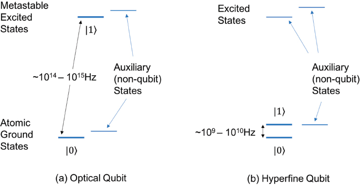
atomic ion with nonzero nuclear spin. The magnetic field can often be designed such that the energy separation between the two qubit states (typically corresponding to the microwave frequency range of 1 to 20 gigahertz [GHz]) is insensitive to the changes in the magnetic field to first order, which lead to long coherence times (1 to 1,000 seconds) [17-19]. Coherent control of hyperfine qubits also requires precise experimental control of the radiation—in this case, either microwave frequencies and phases, or the frequency difference of two laser fields that correspond to the qubit frequency. However, this is much more manageable at microwave than at optical frequencies [20-22].
Qubit measurement is carried out by “state-dependent fluorescence,” where the ion is illuminated with a laser beam that causes only one of the two possible output states to scatter photons repeatedly, which can be measured with an optical detector. The presence or absence of scattered photons indicates which state the qubit is in. High-fidelity qubit state preparation and detection have been demonstrated for both optical (with error rates, or probabilities, of ~10–4)[23] and hyperfine qubits (with error rates of ~10–3) [24,25]. While reliable measurement is possible, as of 2018, the process affects other qubits in the region where the qubit is being measured, and can leave the measured qubit in an excited state. So current systems measure all qubits at the same time, and they need to be “cooled” before being used again.
Single-qubit gate operations are carried out by driving the atomic states with resonant optical (for optical qubits) or microwave (for hyperfine qubits) fields. Hyperfine qubits can also be driven by a pair of laser beams whose frequency difference is precisely tuned to the qubit microwave frequency, via a process called “Raman transition” [26]. Hyperfine qubits driven by microwave fields have reached single qubit gate error rates (defined as the probability that applying a gate yields an incorrect state) in the 10–4 to 10–6 range, limited purely by the inherent coherence time of the qubit rather than any systematic errors in the control fields [27-29]. The key to achieving these error rates is to carefully shape the amplitude of the microwave pulse so that small errors in the pulse width or amplitude cancel out to first order [30-32]. Reaching similar limits with optical control signals had been hampered by the difficulty of stabilizing the laser field experienced by the qubits; ultraviolet (UV) laser beam outputs often used to drive gates can be distorted by mechanical, thermal, and air-density fluctuations in the laser beam path. The availability of single-mode optical fibers that can withstand high levels of UV optical power [33] has led to dramatic increases in the fidelity of microwave qubits using two Raman lasers in recent years. As experimental techniques for controlling systematic errors in the gate-driving optical fields continue to improve, single-qubit gates are reaching error rates of 10–4 to 10–5 [34,35].
To create two-qubit gates, these systems make use of charge interactions between trapped ions. Using either optical or microwave fields, one can excite an ion to oscillate in space such that it induces another ion to move as well. By carefully tuning the frequency of the driving fields, one can arrange the external control field to “push” the ions only if the targeted ion is in a specific qubit state; this mechanism is often called the “state-dependent force.” As long as the excited motion remains fully coherent, it can serve as a “quantum bus” that mediates interaction between the qubits and realizes a two-qubit gate, analogous to an interconnect bus connecting different parts of the chip in an integrated circuit. Novel gate schemes have been developed to make such interactions robust against the exact details of the motion [36-38]. The error rates of the two-qubit gates (characterized by the probability of resulting in the wrong output state) have reached the 10–2 to 10–3 range using both optical [39,40] and microwave fields [41]. The mechanisms that limit this fidelity are known, and researchers continue to work to improve the quality of this operation.
B.3 CONTROL AND MEASUREMENT PLANE
The control system for a trapped ion quantum computer is made of four main subsystems: (1) the RF and DC voltages that operate the trap; (2) the continuous wave (CW) lasers used for “incoherent” operations
such as cooling or reading out qubits; (3) the “coherent qubit control system” responsible for enacting coherent quantum logic gates; and (4) the photon detectors used for measuring the qubit states.
The basic operation of a Paul trap requires an RF source, typically in the frequency range of 20-200 MHz, with voltage amplitudes in the 30-400 V range. The DC voltages in the range of 0-30 V are used to define the trapping potential in the axial direction. In modern microfabricated traps, up to a hundred or more DC electrodes are used, requiring as many voltage sources to control them. Programmable multichannel digital-to-analog converters (DACs) are used to control these traps, which are capable of supporting several chains of ions, splitting and merging actions of ion chains, and physically shuttling ions between different regions of the trap.
The CW lasers are a set of lasers whose frequency is stabilized (typically to one part in 109) to the energy required for qubit transitions. These laser sources typically go through several optical modulators that are used to control the frequency and the amplitude of laser beams applied to the ions. The modulated CW laser beams are used to cool the ions to close to their motional ground state in the trap, to initialize the qubit state (by optical pumping), and for the readout of the qubit by inducing one of the qubit states to scatter photons. Frequency stabilization of these lasers to an absolute frequency reference is routinely accomplished using standard frequency locking setups.
The coherent qubit control system drives all the quantum logic gates in the system, and often dictates the performance of the quantum circuit execution in the quantum processor. The implementation of the coherent control system varies depending on the qubits used: for optical qubits, this tends to be an “ultra-stable frequency” CW laser (typically stabilized to one part in 1013 to 1015), and for hyperfine qubits, it is often two laser beams with the difference frequency locked to the energy difference between the two qubit levels. One also needs a delivery system that can direct these laser beams to the target ions to operate the logic gates. The coherent control is often carried out by modulating these lasers with optical modulators, driven by programmable RF sources. There have been recent proposals where the coherent qubit control can be performed entirely using microwave sources, rather than lasers. Designing and constructing a high-quality coherent qubit control system is a challenging task that will determine the performance of the trapped ion quantum computer, such as individual gate error rates and the ability to run complex circuits.
The detection system often consists of imaging optics that collect photons scattered from the ions, and photon-counting detectors (such as photomultiplier tubes) capable of measuring the collected photons. The detected photons (counts, arrival time, etc.) can be used to reliably determine the state of the qubits.
B.4 NOTES
[1] H. Dehmelt, 1988, A single particle forever floating at rest in free space: New value for electron radius, Physica Scripta T22:102-110.
[2] W. Paul, 1990, Electromagnetic traps for charged and neutral particles, Review of Modern Physics 62:531.
[3] D.J. Wineland, C. Monroe, W.M. Itano, D. Leibfried, B.E. King, and D.M. Meekhof, 1998, Experimental issues in coherent quantum-state manipulation of trapped atomic ions, Journal of Research of the National Institute of Standards and Technology 103:259-328.
[4] J. Chiaverini, B.R. Blakestad, J.W. Britton, J.D. Jost, C. Langer, D.G. Leibfried, R. Ozeri, and D.J. Wineland, 2005, Surface-electrode architecture for ion-trap quantum information processing, Quantum Information and Computation 5:419-439.
[5] J. Kim, S. Pau, Z. Ma, H. R. McLellan, J. V. Gates, A. Kornblit, R. E. Slusher, R. M. Jopson, I. Kang, and M. Dinu, 2005, System design for large-scale ion trap quantum information processor, Quantum Information and Computation 5:515.
[6] D. Stick, W.K. Hensinger, S. Olmschenk, M.J. Madsen, K. Schwab, and C. Monroe, 2006, Ion trap in a semiconductor chip, Nature Physics 2:36-39.
[7] D. Kielpinski, C. Monroe, and D.J. Wineland, 2002, Architecture for a large-scale ion-trap quantum computer, Nature 417:709-711.
[8] R.B. Blakestad, C. Ospelkaus, A.P. VanDevender, J.H. Wesenberg, M.J. Biercuk, D. Leibfried, and D.J. Wineland, 2011, Near-ground-state transport of trapped-ion qubits through a multidimensional array, Physical Review A 84:032314.
[9] D.L. Moehring, C. Highstrete, D. Stick, K.M. Fortier, R. Haltli, C. Tigges, and M.G. Blain, 2011, Design, fabrication and experimental demonstration of junction surface ion traps, New Journal of Physics 13:075018.
[10] K. Wright, J.M. Amini, D.L. Faircloth, C. Volin, S.C. Doret, H. Hayden, C.-S. Pai, D.W. Landgren, D. Denison, T. Killian, R.E. Slusher, and A.W. Harter, 2013, Reliable transport through a microfabricated X-junction surface-electrode ion trap, New Journal of Physics 15:033004.
[11] A.P. VanDevender, Y. Colombe, J. Amini, D. Leibfried, and D J. Wineland, 2010, Efficient fiber optic detection of trapped ion fluorescence, Physical Review Letters 105:023001.
[12] J.T. Merrill, C. Volin, D. Landgren, J.M. Amini, K. Wright, S.C. Doret, C.-S. Pai, H. Hayden, T. Killian, D. Faircloth, K.R. Brown, A.W. Harter, and R.E. Slusher, 2011, Demonstration of integrated microscale optics in surface-electrode ion traps, New Journal of Physics 13:103005.
[13] M. Ghadimi, V. Blūms, B.G. Norton, P.M. Fisher, S.C. Connell, J.M. Amini, C. Volin, H. Hayden, C.-S. Pai, D. Kielpinski, M. Lobino, and E.W. Streed, 2017, Scalable ion-photon quantum interface based on integrated diffractive mirrors, npj Quantum Information 3:4.
[14] C. Ospelkaus, U. Warring, Y. Colombe, K.R. Brown, J.M. Amini, D. Leibfried, and D.J. Wineland, 2011, Microwave quantum logic gates for trapped ions, Nature 476:181.
[15] D.T.C. Allcock, T.P. Harty, C.J. Ballance, B.C. Keitch, N.M. Linke, D.N. Stacey, and D.M. Lucas, 2013, A microfabricated ion trap with integrated microwave circuitry, Applied Physics Letters 102:044103.
[16] C.M. Shappert, J.T. Merrill, K.R. Brown, J.M. Amini, C. Volin, S.C. Doret, H. Hayden, C.-S. Pai, K.R. Brown, and A.W. Harter, 2013, Spatially uniform single-qubit gate operations with near-field microwaves and composite pulse compensation, New Journal of Physics 15:083053.
[17] P.T.H. Fisk, M.J. Sellars, M.A. Lawn, and C. Coles, 1997, Accurate measurement of the 12.6 GHz ‘clock’ transition in trapped 171Yb+ ions, IEEE Transactions on Ultrasonics, Ferroelectrics, and Frequency Control 44:344-354.
[18] C. Langer, R. Ozeri, J.D. Jost, J. Chiaverini, B. DeMarco, A. Ben-Kish, R.B. Blakestad, et al., 2005, Long-lived qubit memory using atomic ions, Physical Review Letters 95:060502.
[19] T. P. Harty, D.T.C. Allcock, C.J. Ballance, L. Guidoni, H.A. Janacek, N.M. Linke, D.N. Stacey, and D.M. Lucas, 2014, High-fidelity preparation, gates, memory, and readout of a trapped-ion quantum bit, Physical Review Letters 113:220501.
[20] H. Dehmelt, 1988, A single particle forever floating at rest in free space: New value for electron radius, Physica Scripta T22:102-110.
[21] S. Olmschenk, K.C. Younge, D.L. Moehring, D.N. Matsukevich, P. Maunz, and C. Monroe, 2007, Manipulation and detection of a trapped Yb+ hyperfine qubit, Physical Review A 76:052314.
[22] T.P. Harty, D.T.C. Allcock, C.J. Ballance, L. Guidoni, H.A. Janacek, N.M. Linke, D.N. Stacey, and D.M. Lucas, 2014, High-fidelity preparation, gates, memory, and readout of a trapped-ion quantum bit, Physical Review Letters 113:220501.
[23] A.H. Myerson, D.J. Szwer, S. C. Webster, D.T.C. Allcock, M. J. Curtis, G. Imreh, J.A. Sherman, D.N. Stacey, A.M. Steane, and D.M. Lucas, 2008, High-fidelity readout of trapped-ion qubits, Physical Review Letters 100:200502.
[24] T. P. Harty, D.T.C. Allcock, C.J. Ballance, L. Guidoni, H.A. Janacek, N.M. Linke, D.N. Stacey, and D.M. Lucas, 2014, High-fidelity preparation, gates, memory, and readout of a trapped-ion quantum bit, Physical Review Letters 113:220501.
[25] R. Noek, G. Vrijsen, D. Gaultney, E. Mount, T. Kim, P. Maunz, and J. Kim, 2013, High speed, high fidelity detection of an atomic hyperfine qubit, Optics Letters 38:4735-4738.
[26] D.J. Wineland, C. Monroe, W.M. Itano, B.E. King, D. Leibfried, D.M. Meekhof, C. Myatt, and C. Wood, 1998, Experimental primer on the trapped ion quantum computer, Fortschritte der Physik 46:363-390.
[27] K.R. Brown, A.C. Wilson, Y. Colombe, C. Ospelkaus, A.M. Meier, E. Knill, D. Leibfried, and D J. Wineland, 2011, Single-qubit-gate error below 10-4 in a trapped ion, Physical Review A 84:030303.
[28] T.P. Harty, D.T.C. Allcock, C.J. Ballance, L. Guidoni, H.A. Janacek, N.M. Linke, D.N. Stacey, and D.M. Lucas, 2014, High-fidelity preparation, gates, memory, and readout of a trapped-ion quantum bit, Physical Review Letters 113:220501.
[29] R. Blume-Kohout, J.K. Gamble, E. Nielsen, K. Rudinger, J. Mizrahi, K. Fortier, and P. Maunz, 2017, Demonstration of qubit operations below a rigorous fault tolerance threshold with gate set tomography, Nature Communications 8:4485.
[30] S. Wimperis, 1994, Broadband, narrowband, and passband composite pulses for use in advanced NMR experiments, Journal of Magnetic Resonance A 109:221-231.
[31] K.R. Brown, A.W. Harrow, and I.L. Chuang, 2004, Arbitrarily accurate composite pulse sequences, Physical Review A 70:052318.
[32] G.H. Low, T.J. Yoder, and I.L. Chuang, 2014, Optimal arbitrarily accurate composite pulse sequences, Physical Review A 89:022341.
[33] Y. Colombe, D.H. Slichter, A.C. Wilson, D. Leibfried, and D.J. Wineland, 2014, Single-mode optical fiber for high-power, low-loss UV transmission, Optics Express 22:19783-19793.
[34] T.P. Harty, D.T.C. Allcock, C.J. Ballance, L. Guidoni, H.A. Janacek, N.M. Linke, D.N. Stacey, and D.M. Lucas, 2014, High-fidelity preparation, gates, memory, and readout of a trapped-ion quantum bit, Physical Review Letters 113:220501.
[35] E. Mount, C. Kabytayev, S. Crain, R. Harper, S.-Y. Baek, G. Vrijsen, S.T. Flammia, K.R. Brown, P. Maunz, and J. Kim, 2015, Error compensation of single-qubit gates in a surface-electrode ion trap using composite pulses, Physical Review A 92:060301.
[36] A. Sørensen and K. Mølmer, 1999, Quantum computation with ions in a thermal motion, Physical Review Letters 82:1971.
[37] D. Leibfried, B. DeMarco, V. Meyer, D. Lucas, M. Barrett, J. Britton, W.M. Itano, B. Jelenkovic, C. Langer, T. Rosenband, and D.J. Wineland, 2003, Experimental demonstration of a robust, high-fidelity geometric two ion-qubit phase gate, Nature 422:412-415.
[38] P.C. Haljan, K.-A. Brickman, L. Deslauriers, P.J. Lee, and C. Monroe, 2005, Spin-dependent forces on trapped ions for phase-stable quantum gates and entangled states of spin and motion, Physical Review Letters 94:153602.
[39] J.P. Gaebler, T.R. Tan, Y. Lin, Y. Wan, R. Bowler, A.C. Keith, S. Glancy, K. Coakley, E. Knill, D. Leibfried, and D.J. Wineland, 2016, High-fidelity universal gate set for 9Be+ ion qubits, Physical Review Letters 117:060505.
[40] C.J. Ballance, T.P. Harty, N.M. Linke, M.A. Sepiol, and D.M. Lucas, 2016, High-fidelity quantum logic gates using trapped-ion hyperfine qubits, Physical Review Letters 117:060504.
[41] T.P. Harty, M.A. Sepiol, D.T.C. Allcock, C.J. Ballance, J.E. Tarlton, and D.M. Lucas, 2016, High-fidelity trapped-ion quantum logic using near-field microwaves, Physical Review Letters 117:140501.


